

Page 1
Intelligent Assembly Solutions
Series
ULTRASONIC GENERATOR/POWER SUPPLY
Servo Systems
ES
AUTOMATED HAND PROBE PRESS
User's Manual
Dukane Part No. 403 – 587– 00
Dukane Intelligent Assembly Solutions • 2900 Dukane Drive • St. Charles, Illinois 60174 USA • TEL (630) 797– 4900 • FAX (630) 797– 4949
Dukane products are manufactured
ISO 9001
in ISO registered facilities.
www.dukane.com/us
Page 2

iQ Series Ultrasonic Generator/Power Supply, Servo Systems, ES User’s Manual
Copyright © 2013 Dukane Intelligent Assembly Solutions
2900 Dukane Drive
St. Charles, IL 60174 USA
Notice of Rights:
All rights reserved. No part of this manual including the interior design, cover design and icons
may be reproduced, transmitted or utilized in any form or by any means, electronic, mechanical,
photocopying, recording, or by any information storage and retrieval system, without written
permission from Dukane Corporation.
Notice of Liability:
The information contained in this manual is distributed on an “As is” basis, without warranty.
While every precaution has been taken in the preparation of this manual, Dukane Corporation
shall not have any liability to any person or entity with respect to any liability, loss, or damage
caused or alleged to be caused directly or indirectly by the instructions contained in this manual,
or by the hardware products described herein.
Specications subject to change without notice.
This user’s manual documents product features, hardware, and controls software available
at the time this user's manual was published.
Printed in the United States of America.
Dukane Part Number: 403-587-00
Dukane ultrasonic equipment is manufactured under one or more of the following U.S. Patents:
(* = Inactive)
3,780,926 * 4,131,505* 4,277,710* 5,798,599 5,880,580 6,984,921 7,225,965 7,475,801,
7,819,158 and, 8,052,816
Page ii
Dukane Manual Part No. 403-587-00
Page 3

Revision History
Revision Revision
Number Summary Date
- 00 Original release. November 20, 2013
Dukane Manual Part No. 403-587-00
Page iii
Page 4

iQ Series Ultrasonic Generator/Power Supply, Servo Systems, ES User’s Manual
This page intentionally left blank
Page iv
Dukane Manual Part No. 403-587-00
Page 5

Contents
Section 1- Introduction .......................1
General User Information .............................3
Press System Overview ..............................4
Key Generator Features..............................4
Section 2 - Health and Safety ..................5
General Considerations ..............................7
Plastics Health Notice................................8
Electrical Safety ....................................8
Lifting the Equipment ...............................10
Section 3 - Installation ....................... 11
Before Installation..................................13
Unpacking........................................15
Placement........................................15
Rear Panel Layout Overview .........................16
AC Power Inlet Panel .................................17
System I/O Panel.....................................17
RFI Grounding ....................................25
Connector Descriptions .............................26
Power Cords......................................28
Cable Connections .................................29
Networking . . . . . . . . . . . . . . . . . . . . . . . . . . . . . . . . . . . . . . . 36
Recheck Connections...............................36
Connect AC Power.................................36
Section 4 - Control Panel.....................37
Overview.........................................39
System Operating Mode Keys ........................40
Navigation Keys ...................................41
System Power Output Level ..........................42
Screen Basics.....................................43
Dukane Manual Part No. 403-587-00
Continued
Page v
Page 6

iQ Series Ultrasonic Generator/Power Supply, Servo Systems, ES User’s Manual
Continued from Previous Page
Section 5 - Operation ........................45
Overview.........................................47
Generator Start-up Sequence ........................47
Stopping the Weld Cycle ............................48
Using the Menus...................................49
Set-up Guidelines..................................93
Section 6 - Optional Control ..................95
Other Control Functions.............................97
Stopping the Weld Cycle ............................97
Software Support Features ..........................97
Quick Start Using iQ Explorer II.....................99
Contents
Unique Features .................................111
Section 7 - System Operational Testing........113
Section 8 - Maintenance.....................121
Section 9 - Options.........................125
Section 10 - Contacting Dukane ..............131
Section 11 - Specications ..................135
Generator Outline Drawings.........................137
Weights, Dimensions, Operating Environment ..........140
AC Power Requirements ...........................141
Ultrasonic Pressure ...............................142
Interpreting the Model Number ......................143
Regulatory Agency Compliance......................144
Section 12 - Appendices....................145
Appendix A - List of Figures .........................147
Appendix B - List of Tables..........................152
Page vi
Appendix C - Sequencing Notes .....................153
Appendix D - Alarm Messages.......................156
Appendix E - Menu Structure Diagrams................161
Index .................................. 165
Dukane Manual Part No. 403-587-00
Page 7

Section 1 - Introduction
SECTION 1
Introduction
General User Information . . . . . . . . . . . . . . 3
Press System Overview . . . . . . . . . . . . . . . 4
Key Generator Features . . . . . . . . . . . . . . . 4
Dukane Manual Part No. 403-587-00
Page 1
Page 8

iQ Series Ultrasonic Generator/Power Supply, Servo Systems, ES User’s Manual
This page intentionally left blank
Page 2
Dukane Manual Part No. 403-587-00
Page 9
General User Information
Read this Manual First
Before operating your ultrasonic system, read this User’s
Manual to become familiar with the equipment. This will
ensure correct and safe operation. The manual is organized
to allow you to learn how to safely operate this equipment.
The examples given are chosen for their simplicity to illustrate basic operation concepts.
This manual provides information to set up, operate, and
interface this generator/power supply as an integral part of
Dukane’s iQ Series ES press system.
Particular models are listed in Section 11 - Specications
Notes, Cautions and Warnings
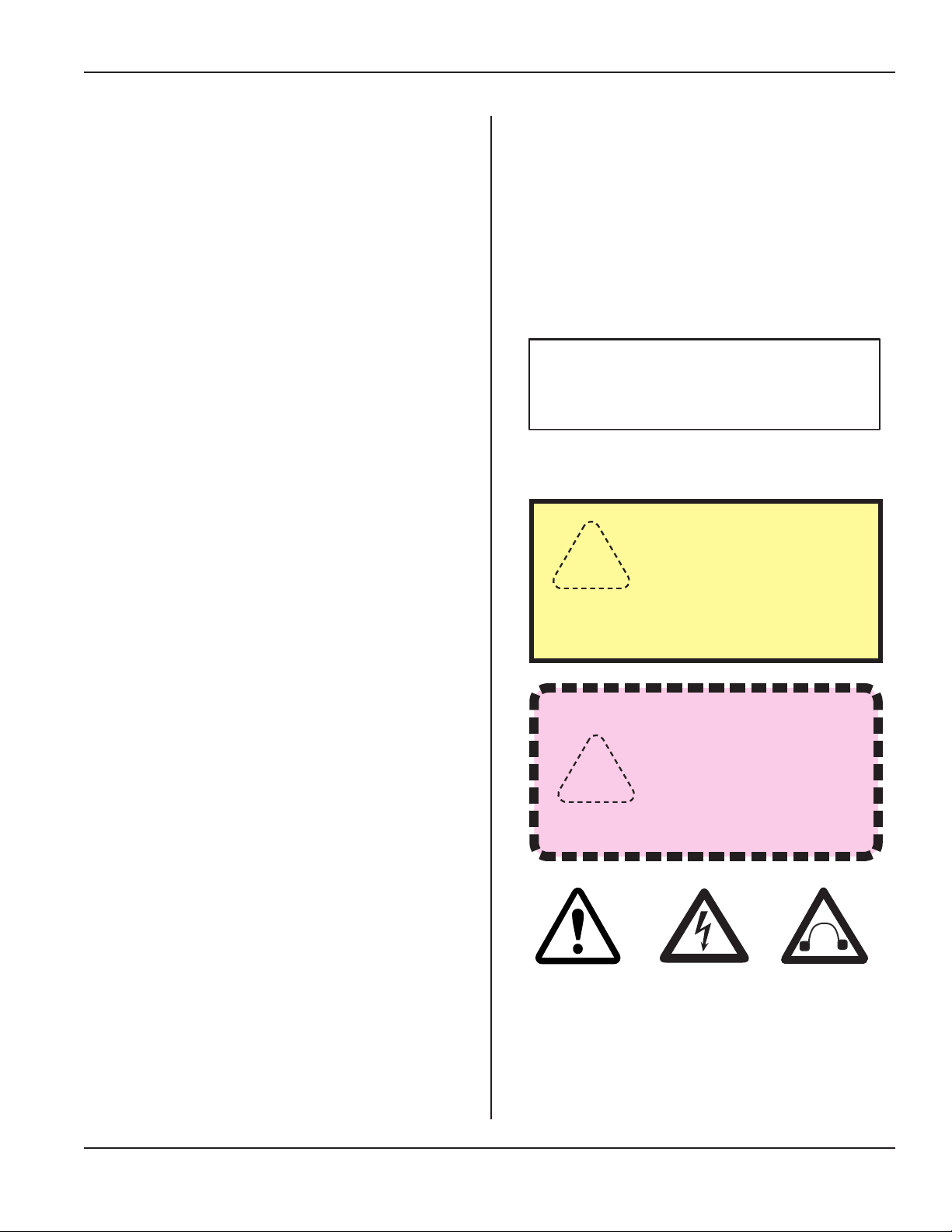
Throughout this manual we use NOTES to provide information that is important for the successful application and
understanding of the product. A NOTE block is shown to
the right.
In addition, we use special notices to make you aware
of safety considerations. These are the CAUTION and
WARNING blocks as shown here. They represent increasing levels of important information. These statements help
you to identify and avoid hazards and recognize the consequences. One of three different symbols also accompany
the CAUTION and WARNING blocks to indicate whether
the notice pertains to a condition or practice, an electrical
safety issue or a operator protection issue.
Drawings and Tables
The gures and tables are identied by the section number followed by a sequence number. The sequence num-
ber begins with one in each section. The gures and
tables are numbered separately. The gures use Arabic
sequence numbers (e.g. –1, –2, –3) while the tables use
Roman sequence numerals (e.g. –I, –II, –III). As an example, Figure 3–2 would be the second illustration in section three while Table 3–II would be the second table in
section three.
Section 1 - Introduction
NOTE
Note statements provide additional
.
information or highlight procedures.
CAUTION
Caution statements
identify conditions or
practices that could result
in damage to the equipment or other
property.
WARNING
Warning statements
point out conditions or
practices that could result in personal injury or
loss of life.
Condition
or Practice
Electrical
Safety Issue
Operator
Protection
(hearing)
Dukane Manual Part No. 403-587-00
Page 3
Page 10

iQ Series Ultrasonic Generator/Power Supply, Servo Systems, ES User’s Manual
Press System Overview
An iQ Series Ultrasonic Press System ES consists of
these components: the iQ generator, press (with thruster,
switches, controls, cables, transducer, booster, horn, and
xture) and iQ Explorer II software. The software allows
the operator to control the system either remotely or at the
press location.
The iQ Series ES generator has rugged internal ultrasonic
circuitry and ensures a continuous resonant frequency lock
at the start of each weld.
The generator’s compact size allows multiple units to be
placed into an industrial equipment cabinet. This generator will operate at the same international line voltage input
specications as the other generators of this product family (unless the 120V option is installed). It also includes an
RFI line lter that passes FCC, CE, UL, and CSA testing
for global applications.
Key Generator Features
• The Generator Interface has a 5" LCD color display
and soft keys that enhance the intuitive menu navigation.
• Digital Control of all power supply functions, includ-
ing digital frequency synthesis, and parameters allows
for unique congurations and allows for future upgrades.
• Process Parameters such as frequency, amplitude
and power are all updated at a 0.5 ms rate.
• Pulse Width Modulation incorporates patented
circuitry giving the power supply the ability to
efciently change and maintain the output amplitude.
This makes it possible to start large horns with reduced
power. It also provides more power-efcient switch-
mode generator operation and increased reliability.
• Linear Ramp Up/Down circuitry allows the acoustic
stack to be brought to operating amplitude smoothly,
minimizing start-up surges and undue stress to stack
and generator. This circuitry also allows decreases to
amplitude as the weld cycle ends. The stack is brought
down from its maximum operating amplitude smoothly, reducing shock stress.
• Digi-Trac Tuning tracks the resonant frequency of the
acoustic stack (horn, booster, and transducer) and ad-
justs the generator output frequency to match it. This
is done for every weld cycle and eliminates the need
to manually tune the generator.
• Line Voltage Regulation automatically maintains
constant amplitude regardless of line voltage devia-
tion. The available output power is maintained
with any voltage input within the specied range.
This provides consistent system performance regardless of line voltage uctuations. It also eliminates the need for bulky, external constant–voltage
transformers.
• Load Regulation provides constant ultrasound
amplitude automatically regardless of power draw.
The ultrasonic output amplitude level is held to
within ±1% to provide weld process consistency
and reduced weld cycle times.
• Wide Line Voltage Operation means that stan-
dard systems will operate worldwide within their
standard AC voltage ranges.
• Flow Through Cooling Tunnel with a matched
high–performance heat sink and thermostatically
controlled fan reduces thermal gradients and increases component life.
• AC Power Inrush protection reduces electri-
cal stress on the internal components by protecting them from AC power startup transient current
surges.
• Multiple Electronic Overload protection circuits
prevent instantaneous component failure in the
event of extreme output overload conditions. The
overload power limit is based on the actual true RMS
power output level.
• Process Limits include: distance, weld peak force,
position, weld energy, and peak power. These programmable limits provide the means to adapt to a
wide variety of welding applications.
• Rear Panel Expansion Slot is available to allow
for custom congurations for OEM and cost effec-
tive solutions.
• RS-232 Serial Conguration Port is used for
eld software upgrades, troubleshooting and ad-
vanced hardware setup with optional PC-based
congurator.
• CECertication means that the system meets the
required European standards to be sold and used in
Europe (high line voltage models only).
• ISO9001Certication means that this system has
been manufactured to high quality standards and
assures you of manufacturing excellence.
• TUV Certication - TÜV Rheinland certies
Dukane products comply with applicable UL (Underwriters Laboratories) and CSA (Canadian Standards Association) requirements.
Page 4
Dukane Manual Part No. 403-587-00
Page 11

Section 2 - Health and Safety
SECTION 2
Health and Safety
General Considerations . . . . . . . . . . . . . . . . 7
Plastics Health Notice . . . . . . . . . . . . . . . . . 8
Electrical Safety ..............................8
Domestic Power Grounding ...................... 9
International Power Grounding .................... 9
Lifting the Equipment .........................10
Dukane Manual Part No. 403-587-00
Page 5
Page 12

iQ Series Ultrasonic Generator/Power Supply, Servo Systems, ES User’s Manual
This page intentionally left blank
Page 6
Dukane Manual Part No. 403-587-00
Page 13
Section 2 - Health and Safety
General Considerations
Please observe these health and safety recommendations for safe, efcient, and injury-free operation of your
equipment.
Proper Installation - Operate system components only
after they are properly installed.
NoUnauthorizedModications- Do not modify your
system in any way unless authorized to do so by Dukane
Corporation. Unauthorized modications could cause
equipment damage and/or injury to the operator. In addition, unauthorized modications will void equipment
warranty.
Keep the Cover On - Do not remove any equipment
cover unless directed to do so by Dukane Corporation. The
generator produces hazardous electrical voltages which
could cause injury.
Grounded Electrical Power - Operate this equipment
only with a grounded electrical connection.
See Electrical Safety for grounding instructions, Page 9.
Comply with Regulations - You may be required to add
accessories to bring the system into compliance with
applicable regulations (OSHA in the USA) for machine
guarding and noise exposure.
Use Eye Protection - Wear ANSI approved safety impact
goggles.
Acoustic Stack Hazard - When an acoustic stack (transducer, booster, horn and tip) is energized by the ultrasound
signal, it presents a potential hazard. Stay clear of an
energized stack.
NOTE
These recommendations apply to the
welding system. System in this manual
refers to a complete group of components
associated with the welding of parts, also
known as an ultrasonic assembly system.
A typical iQ Series System consists of the
iQ generator, a press with thruster, switches, controls, cables, transducer, booster,
horn, and xture, and iQ Explorer II software.
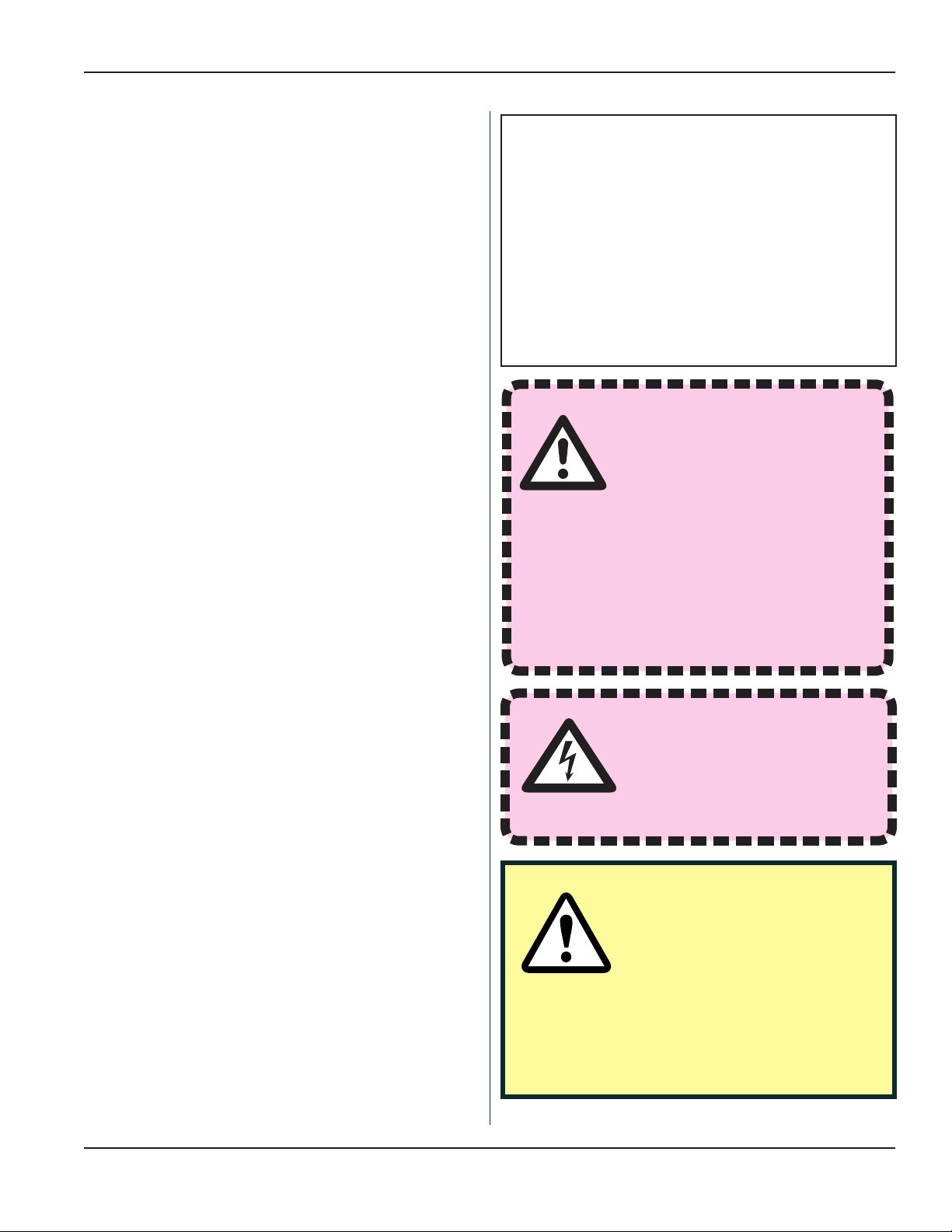
WARNING
Any xture manufactured by
a third party must comply
with all OSHA and ANSI re-
quirements. All xtures must
be guarded as necessary.
Dukane Corporation does not
assume any responsibility or liability for xtures manufactured
by the customer or any third
party manufacturer.
WARNING
Never operate the generator
with the cover off. This is
an unsafe practice and may
cause injury.
System E-STOP (abort) Switch - Install a system E-
STOP (abort) switch at each operator station when ultra-
sonic plastic assembly equipment is used with automatic
material handling equipment in an automated system.
Foot Switch - Do not use a foot switch. Using a foot
switch in place of the optical touch nger switches (operate switches) violates OSHA regulations. Do not install
a foot switch.
Dukane Manual Part No. 403-587-00
CAUTION
At some time you may be asked
to remove equipment covers
by the Dukane Service Dept.
personnel. Before doing so,
disconnect the unit electrically from the incoming line AC power. If the unit is a press/
thruster, lock the Air Lockout Valve, located
on the rear panel, in its closed position.
Continued
Page 7
Page 14
iQ Series Ultrasonic Generator/Power Supply, Servo Systems, ES User’s Manual
Continued from Previous Page
General Considerations
System Electrical Cabling - Electrical power must be
off when connecting or disconnecting electrical cables.
Do Not Wear Loose Clothing or Jewelry - They can
become caught in moving parts.
Stay Alert - Watch what you are doing at all times. Use
common sense. Do not operate the press when you are
tired or distracted from the job at hand.
Do Not Operate the Equipment - Your judgement or
reexes could be impaired while taking prescription medi-
cations. If so, do not operate the equipment. Be familiar
with warning labels and recommended activity restrictions
that accompany your prescription medications. If you have
any doubt, do not operate the equipment.
Plastics Health Notice
Certain plastic materials, when being processed, may
emit fumes and/or gases that may be hazardous to the
operator’s health. Proper ventilation of the work station
should be provided where such materials are processed.
Inquiries should be made to the U.S. Department of Labor
concerning OSHA regulations for a particular plastic prior
to processing with Dukane ultrasonic equipment.
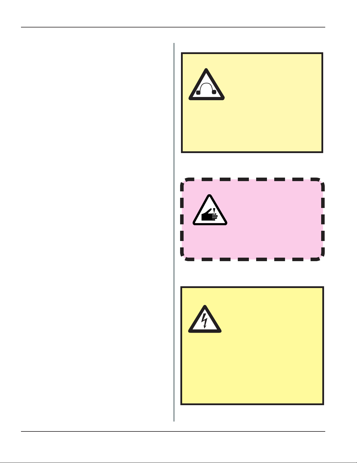
CAUTION
Parts being joined ultrasonically will at times vibrate at
audible frequencies. Wear ear
protectors to reduce annoying
or uncomfortable sounds. In
addition, ultrasound bafes, sound enclosures, or materials that absorb sound may be
located to surround the system. Ultrasound
pressure level could exceed 110dB. See
Ultrasonic Pressure, Table 11-IV, Page 142.
WARNING
Keep head, hands, limbs
and body at least six
inches (152 mm) away
from an operating press/
thruster. A vibrating, descending horn
can cause burns and/or crushing
injuries.
Electrical Safety
The iQ Series generator provides the operating power
and power returns. Make sure the generator is grounded
properly.
In addition to the safety considerations, proper grounding
is essential for the effective suppression of RFI (Radio
Frequency Interference). Every generator contains a RFI
lter which blocks noise on the AC power line from entering the generator control circuitry. This lter also prevents
ultrasonic RFI from being fed back into the AC power line.
If you experience problems with RFI from the press, run
an additional grounding wire from the press base grounding stud to the nearest grounded metal pipe or equivalent
earth ground by means of a ground clamp. Use at least 14
AWG wire for the connection to the press base.
Page 8
CAUTION
When making cable connections to system equipment
or disconnecting cables
from system equipment,
make sure electrical power to the system
is turned off, and AC power cords are
removed from their receptacles. After the
cables have been securely connected
and the connections and cable routing
checked a nal time, the power may be
restored.
Continued
Dukane Manual Part No. 403-587-00
Page 15
Continued from Previous Page
Section 2 - Health and Safety
Electrical Safety
Domestic Power Grounding
For safety, the power cords used on this product have a
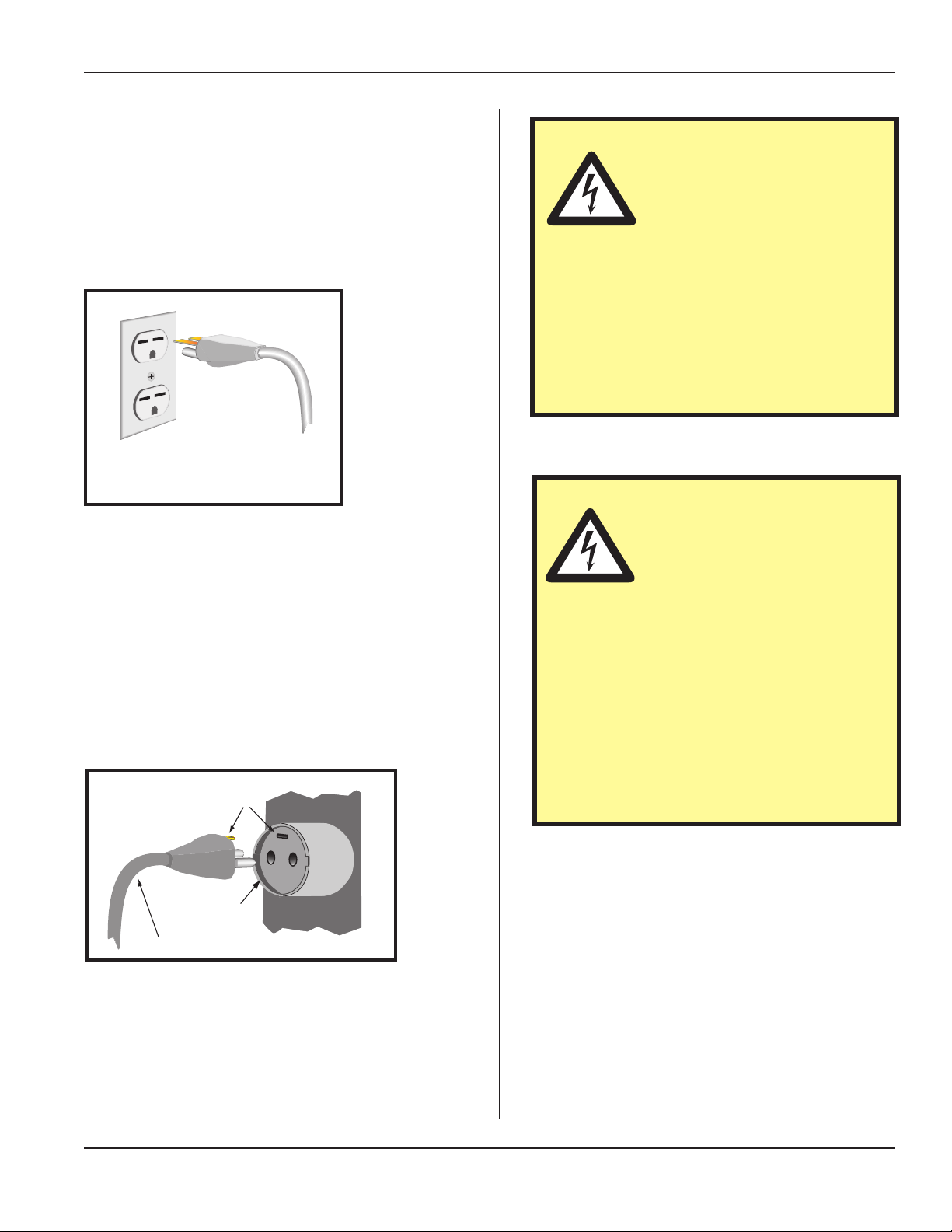
three-wire, grounding-type power cord. Figure 2-1 illustrates the appropriate electrical outlet to use with the
power cord that is included with systems shipped to North
America.
Approved 2 pole, 3 wire grounding
receptacle HUBBELL No. 5652 or
equivalent to NEMA 6–15R or 6–20R
Figure 2–1 Example of 220/240 Volt,
Grounded, 3-Prong Receptacle
International Power Grounding
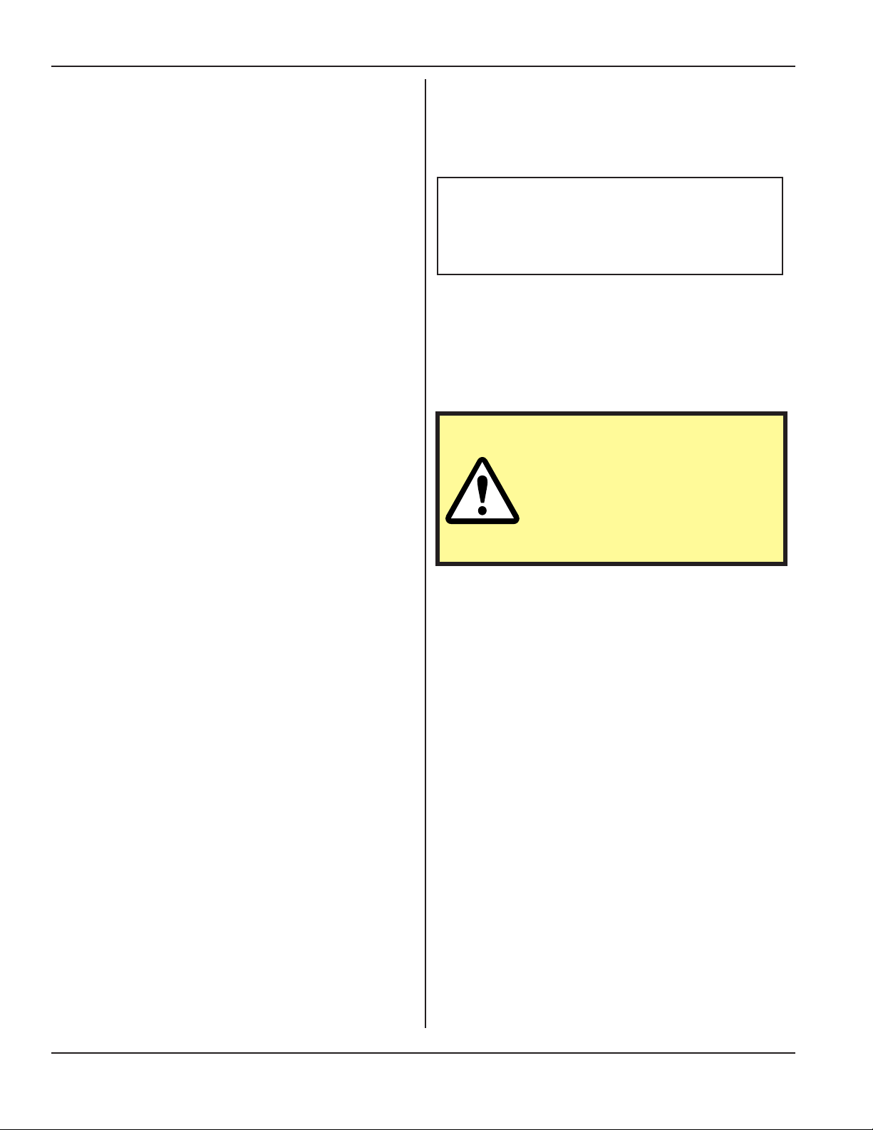
The power cable normally provided for international use is
compatible with the power outlet used in many Continental European countries (Refer to Figure 2–2.) However,
if your application requires another type of power cord,
check with your equipment supplier, and follow local regulations concerning proper wiring and grounding.
CAUTION
If you have a two-prong electrical receptacle, we strongly
recommend that you replace
it with a properly grounded
three-prong type. Have a qualied electrician replace it following the National
Electric Code and any local codes and
ordinances that apply.
See Figures 2–1 and 2–2.
CAUTION
If there is any question about
the grounding of your receptacle, have it checked by a
qualied electrician. Do not
cut off the power cord grounding prong,
or alter the plug in any way. If an extension cord is needed, use a three-wire
cord that is in good condition. The cord
should have an adequate power rating
to do the job safely. It must be plugged
into a grounded receptacle. Do not use a
two-wire extension cord with this product.
Grounding Contacts
Typical Outlet
Provided Cable
Figure 2–2 International 220/240V Grounding
Dukane Manual Part No. 403-587-00
100/120 Volt AC Systems (North America or
Japan)
The power cord (including strain relief) supplied
with the 100/120VAC systems is permanently
attached to the rear of the generator. Units with this
power cord are for use in North America or Japan.
240V Systems
High power generators with power ratings above
2400W also use permanently attached power cords.
Page 9
Page 16
iQ Series Ultrasonic Generator/Power Supply, Servo Systems, ES User’s Manual
Lifting the Equipment
How to Lift Safely
• Before lifting, take a moment to think about what
you’re about to do.
• Examine the object for sharp corners, slippery spots
or other potential hazards. Know your limit and don’t
try to exceed it.
• Ask for help if needed, or if possible, divide the load
to make it lighter.
• Know where you are going to set the item down, and
make sure it and your path are free of obstructions.
Then follow these steps:
1. Stand close to the load with your feet spread
apart about shoulder width, with one foot
slightly in front of the other for balance.
2. Squat down bending at the knees (not your
waist). Tuck your chin while keeping your
back as vertical as possible.
3. Get a rm grasp of the object before beginning the lift. Begin slowly lifting with your
LEGS by straightening them. Never twist
your body during this step.
For equipment weights see Page 140,
Table 11-I in Section 11, Specications.
Take care when lifting the
equipment. We recommend
using a mechanical lift device
to assist.
NOTE
CAUTION
4. Once the lift is complete, keep the object as
close to the body as possible. As the load’s
center of gravity moves away from the body,
there is a dramatic increase in stress to the
lumbar region of the back.
5. If you must turn while carrying the load,
turn using your feet-not your torso. To place
the object below the level of your waist, follow the same procedures in reverse order.
Remember, keep your back as vertical as
possible and bend at the knees.
Page 10
Dukane Manual Part No. 403-587-00
Page 17

Section 3 - Installation
SECTION 3
Installation
Before Installation...........................13
When to Use Lockout/Tagout Devices ............... 13
Unpacking . . . . . . . . . . . . . . . . . . . . . . . . . . . . . . . . 15
Placement . . . . . . . . . . . . . . . . . . . . . . . . . . . . . . . . 15
Rear Panel Layout Overview .................. 16
AC Power Inlet Panel ......................... 17
System I/O Panel............................. 17
RFI Grounding ............................ 25
Connector Descriptions ...................... 26
Power Cords...............................28
Cable Connections ......................... 29
Networking . . . . . . . . . . . . . . . . . . . . . . . . . . . . . . . . 36
Recheck Connections . . . . . . . . . . . . . . . . . . . . . . . 36
Connect AC Power .......................... 36
Dukane Manual Part No. 403-587-00
Page 11
Page 18

iQ Series Ultrasonic Generator/Power Supply, Servo Systems, ES User’s Manual
This page intentionally left blank
Page 12
Dukane Manual Part No. 403-587-00
Page 19
Before Installation
As you plan for the installation of your generator,
please consider these important subjects as listed
below:
• When to use lockout / tagout devices
• Lifting the generator safely - See Section 2 -
Health and Safety, Page 10.
When to Use Lockout /
Tagout Devices
Section 3 - Installation
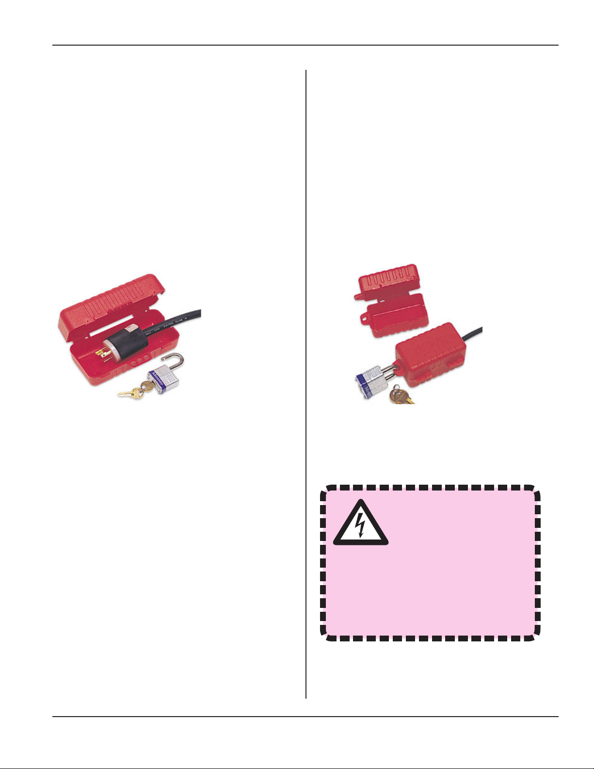
Figure 3-1 Lockout Device In Open Position, Unlocked
The typical kind of LOTO device for this generator
is a clam shell type device (with lockout capability).
The LOTO device is placed over the plug end of the
generator electrical cord. This effectively prevents
access to the energy isolation point. See the example
of one such device in the gure above.
The gure to the right shows the lockout device in the
closed, locked position.
Figure 3-2 Bottom Lockout Device In Closed
Position, Locked
WARNING
Electrical safety hazards exist inside the
generator chassis.
Before making any internal adjustments to the generator, apply
a lockout/tagout (LOTO) device to
the generator chassis.
Continued
Dukane Manual Part No. 403-587-00
Page 13
Page 20

iQ Series Ultrasonic Generator/Power Supply, Servo Systems, ES User’s Manual
Continued from Previous Page
Lockout/Tagout
Procedure to use BEFORE making any internal
adjustments to the generator:
1. Push the generator's AC power switch/breaker to
the OFF position.
2. Unplug the generator's electrical cord from its
source.
3. Authorized personnel apply a lockout/tagout
(LOTO) device to the plug end of the generator's
electrical cord. Using a typical clam shell type
LOTO device:
1) Open the clam shell.
2) Place the electrical cord plug end inside the
shell.
3) Close the shell.
4) Secure the shell with its lock, and lock it.
4. Wait a minimum of ve minutes for the generator
to discharge its electrical energy.
5. After taking these steps, make the necessary
adjustments to the generator.
Assuming the generator is being put back into service.
Procedure to use AFTER making any internal
adjustments to the generator:
1. Authorized personnel remove the lockout/tagout
device from the plug end of the generator's
electrical cord. Using a typical clam shell type
LOTO device:
1) Unlock the protective shell.
2) Open the shell, exposing the electrical cord
end.
3) Remove the LOTO device, and set it aside.
2. Plug the generator's electrical cord into its AC
power source.
3. Push the generator's AC power switch/breaker to
the ON position.
Page 14
Dukane Manual Part No. 403-587-00
Page 21
Unpacking
Carefully open your shipping container, and make sure
it contains the items shown on the shipping documents.
Inspect all items, and report any damage immediately.
Placement
Generator placement and cable routing should permit
easy access and not interfere with normal system operation.
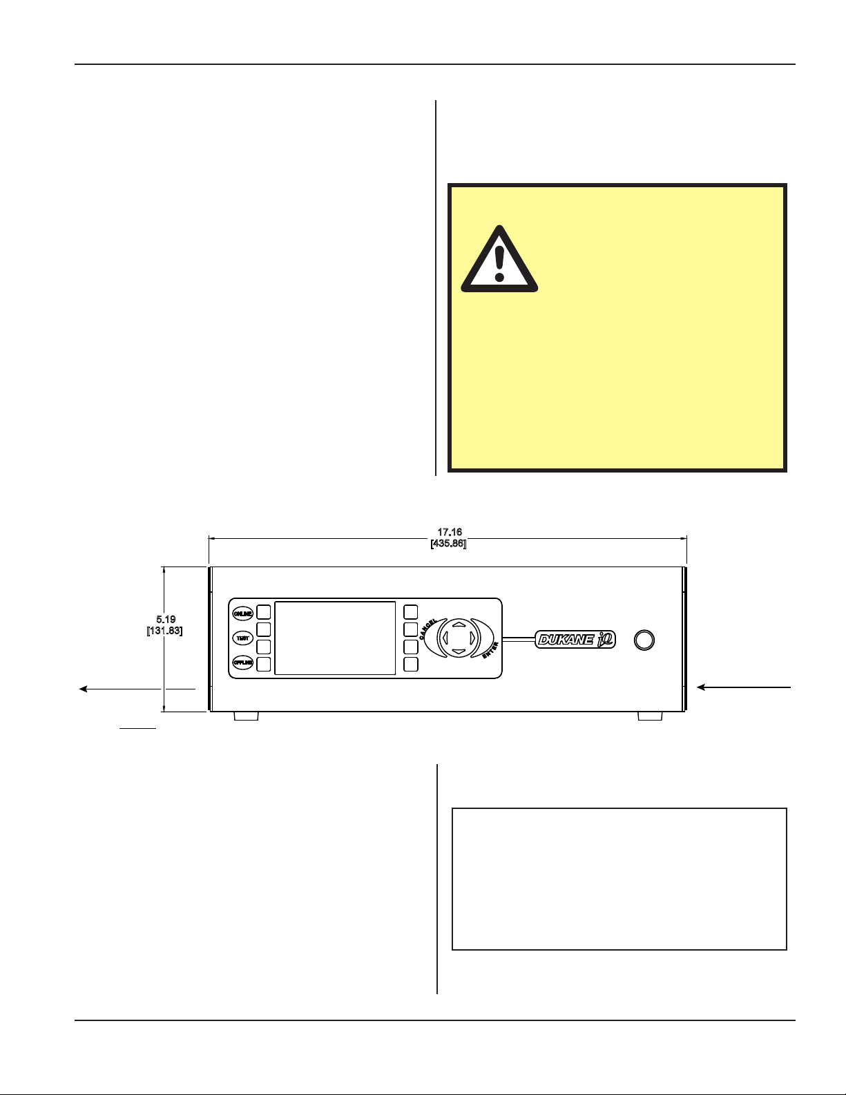
Allow at least 5 inches [13 cm] of space on both ends of
the generator chassis for air circulation. Allow space between 3-6 inches, [8-15 cm] - at the rear of the chassis
for cable clearance. (The amount of space depends on the
chassis type and what rear panel connections there are.)
See Section 11 - Specications, for generator drawings.
Section 3 - Installation
CAUTION
Allow 5 inches for air ventila-
tion at the cooling air inlet and
at the exhaust air outlet. The
fan draws in fresh air to cool
the internal components, reduce thermal
gradients and increase component life.
If excessive dust accumulates in the slots,
wipe or vacuum them clean. Do not use
compressed air as this may force the dust
inside the chassis.
5.19
[131.83]
Exhaust Air
Outlet
IN
[mm]
Figure 3-3 Generator Front View (Typical High Prole)
17.16
[435.86]
Cooling Air Inlet
NOTE
Active Seismic Region Placement - If the
generator will be put in an active seismic
region, please refer to Application Note
511 at, http://www.dukane.com/us/
DL_ApplData.asp
Dukane Manual Part No. 403-587-00
Page 15
Page 22
iQ Series Ultrasonic Generator/Power Supply, Servo Systems, ES User’s Manual
Rear Panel Layout Overview
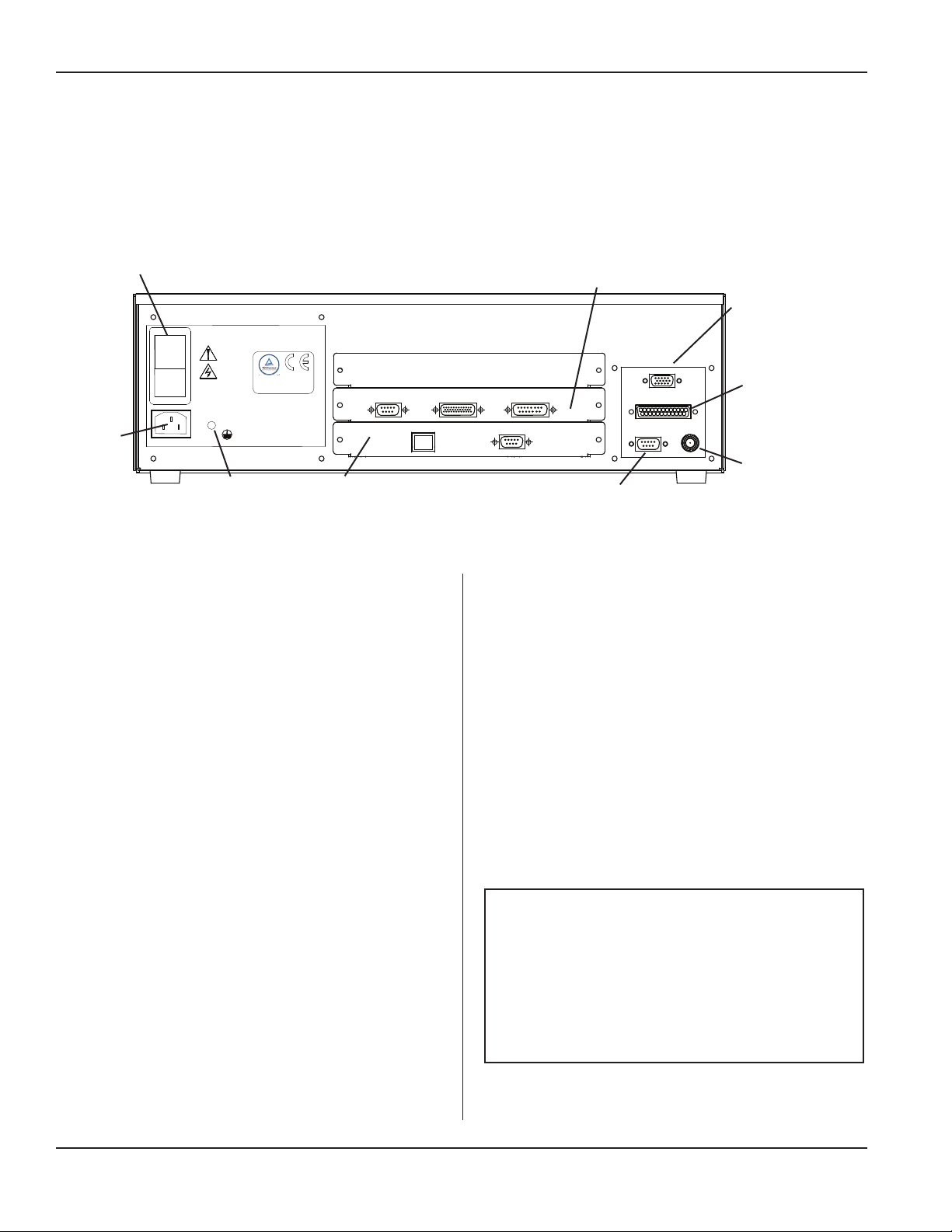
This section provides an overview of the generator rear
panel layout, which includes panel areas dedicated to various standard system functions and options that are available. Figure 3-4 illustrates a typical panel layout.
B
DUKANE CORP.
ST. CHARLES IL. 60174
C
UL: 1012:2010
CSA: C22.2 61010-1-12
IEC: 61010-2012
DISCONNECT LINE POWER
BEFORE REMOVING COVER
PE
C
MADE IN U.S.A.
US
-WARNING-
POWER LINE OUTLET
MUST BE GROUNDED
U.S. PATENTS 7,475,801
7,819,158 AND 7,225,965
J6 BASE/ABORT
J9 ETHERNET
H
I
LINE VOLTAGE:
200-240 Vac
0
50/60Hz, 10A
A
Figure 3-4 Generator Rear Panel
AC Power Inlet Panel
A IEC Power Inlet Connector – Attaches to an IEC style
power cord.
B Power Switch – Circuit Breaker – Used to switch sys-
tem power ON and OFF.
C Chassis Grounding Stud – Chassis connection for a
protective earth ground.
The System I/O Panel
K
D
J5 THRUSTER
J11 ENCODER
J10 RS-232
SYSTEM INPUTS
SYSTEM OUTPUTS
CONFIGURATION
J4
J2
J3
ULTRASOUND
J1
E
F
G
Options Module Panel
H Communications Board (See NOTE below.)
Shown in the example above are these ports:
J9 - Ethernet
J10 - Serial RS-232
K Press Interface Module (See NOTE below.)
Shown in the example above are these ports:
J6 - Base/Abort
D System Input Connector (J2) – Connections for sys-
tem control input signals.
E System Output Connector (J3) – Connections for sys-
tem status output signals.
F Ultrasound Output Connector (J1) – Coaxial high volt-
age connection to ultrasonic stack.
G Conguration Port Connector (J4) – Digital control
port to modify system parameters.
Page 16
J5 - Thruster
J11 - Encoder
NOTE
The press interface board is available in
several different congurations.
See Section 9, Options for more infor-
mation about Data Transfer using the
Communications Board and more about
the Press Interface Module.
Dukane Manual Part No. 403-587-00
Page 23
Section 3 - Installation
AC Power Inlet Panel
The standard AC power inlet panel is described in this section.
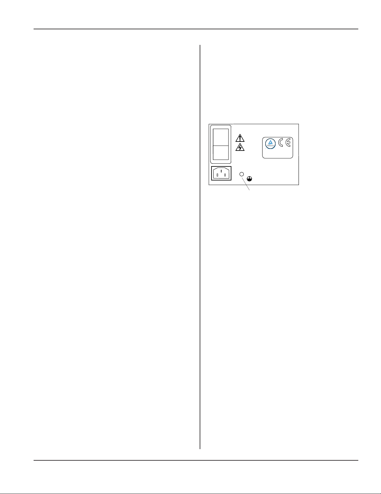
IEC AC Power Inlet Connector
The IEC AC power inlet connector mounted on the system
AC power inlet panel requires a properly congured IEC
compliant power cord, which enables worldwide system
operation by simply changing the power cord.
Low prole systems are equipped with a 10 amp rated IEC
inlet connector. The high prole systems include a 16/20
amp rated IEC inlet connector. 120VAC and 3600/4800W
systems include a non-detachable power cord.
An appropriately rated power cord must be securely attached to the welding system’s IEC inlet connector. If the
correct power cord conguration is not included with the
system for the local AC power outlet at your location, an
appropriate IEC power cord should be available from a
local electrical parts supplier. Note that the system undervoltage lockout will inhibit system operation if a North
American power cord congured for 120V is connected to
the system. A minimum of 180V is required for the system
to operate.
Fixed AC Power Cords
For some models an appropriately rated AC power cord is
permanently mounted to the power inlet panel.
Power Switch/Circuit Breaker
The power switch/circuit breaker has a rocker type actuator switch that will activate or deactivate the AC power
to the system. The power ON position is marked with the
internationally recognized I symbol, the power OFF position is marked with the 0 symbol. This power switch also
integrates an appropriately sized over-current protection
circuit breaker function in the generator.
If an over-current condition trips the circuit breaker, it will
automatically switch to the OFF position. If the overload
current that caused the circuit breaker to trip is due to a
transient condition, the circuit breaker can be reset by
switching the actuator back to the ON position. If when
resetting the circuit breaker after it has tripped, it immediately trips again, there is likely an internal system malfunction, and the generator will require service.
Do not repeatedly try to reset the circuit breaker. If it trips,
this will only cause more damage to the generator.
Chassis Grounding Stud
The chassis grounding stud is used to attach a protective earth ground to the generator. This will aid in the
suppression of electrical interference or radio frequency
interference (RFI) that is common in a industrial envi-
ronment. The chassis ground stud is C in Figure 3-5.
Proper system grounding is discussed on Page 9.
DUKANE CORP.
ST. CHARLES IL. 60174
I
LINE VOLTAGE:
200-240 Vac
0
50/60Hz, 10A
MADE IN U.S.A.
US
C
UL: 1012:2010
CSA: C22.2 61010-1-12
IEC: 61010-2012
-WARNING-
POWER LINE OUTLET
MUST BE GROUNDED
DISCONNECT LINE POWER
BEFORE REMOVING COVER
U.S. PATENTS 7,475,801
PE
7,819,158 AND 7,225,965
C
Figure 3-5 IEC AC Power Inlet Connector
System I/O Panel
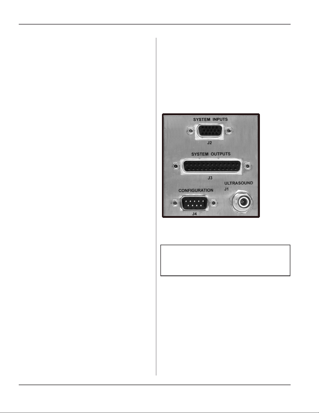
The standard system I/O panel is described in this section. See Figure 3-6 on the next page.
System Inputs Connector
The SYSTEM INPUTS connector mounted on the system I/O panel includes connections for all of the basic
system control input signals, that will typically come
from an automated control system. The cable attached to
this connector includes all of the available system control signals, which will be controlled by an output card
or output port on the automation controller.
The user can determine which signals to use for each
particular welding application, but there must be at least
one connection to this connector in order to activate the
ultrasound output. All of the input signals on this connector are electrically isolated (signals are NOT referenced
to chassis ground) and activated when a 24VDC voltage
source is connected to the signal input pin, referenced
to the isolated common pin. The electrically isolated input signals can be driven from an automation controller
output that is either sinking (NPN) or sourcing (PNP),
depending upon how the isolated common connection
is terminated. All inputs sink or source 10mA of current
from a 24VDC power supply.
Continued
Dukane Manual Part No. 403-587-00
Page 17
Page 24
iQ Series Ultrasonic Generator/Power Supply, Servo Systems, ES User’s Manual
Continued from Previous Page
Note that a simple switch closure (relay contact) connected to a control input can not activate the input without adding an external power supply to power the input.
Adding jumper connections to pins available on the System Inputs connector, can congure switch closure inputs
to operate referenced to generator chassis ground (nonisolated), without adding a separate power supply, if desired.
Refer to Application Note AN507 (Automation Interface
Guidelines) at http://www.dukane.com/us/DL_ApplDa-
ta.asp for wiring diagrams of example applications.
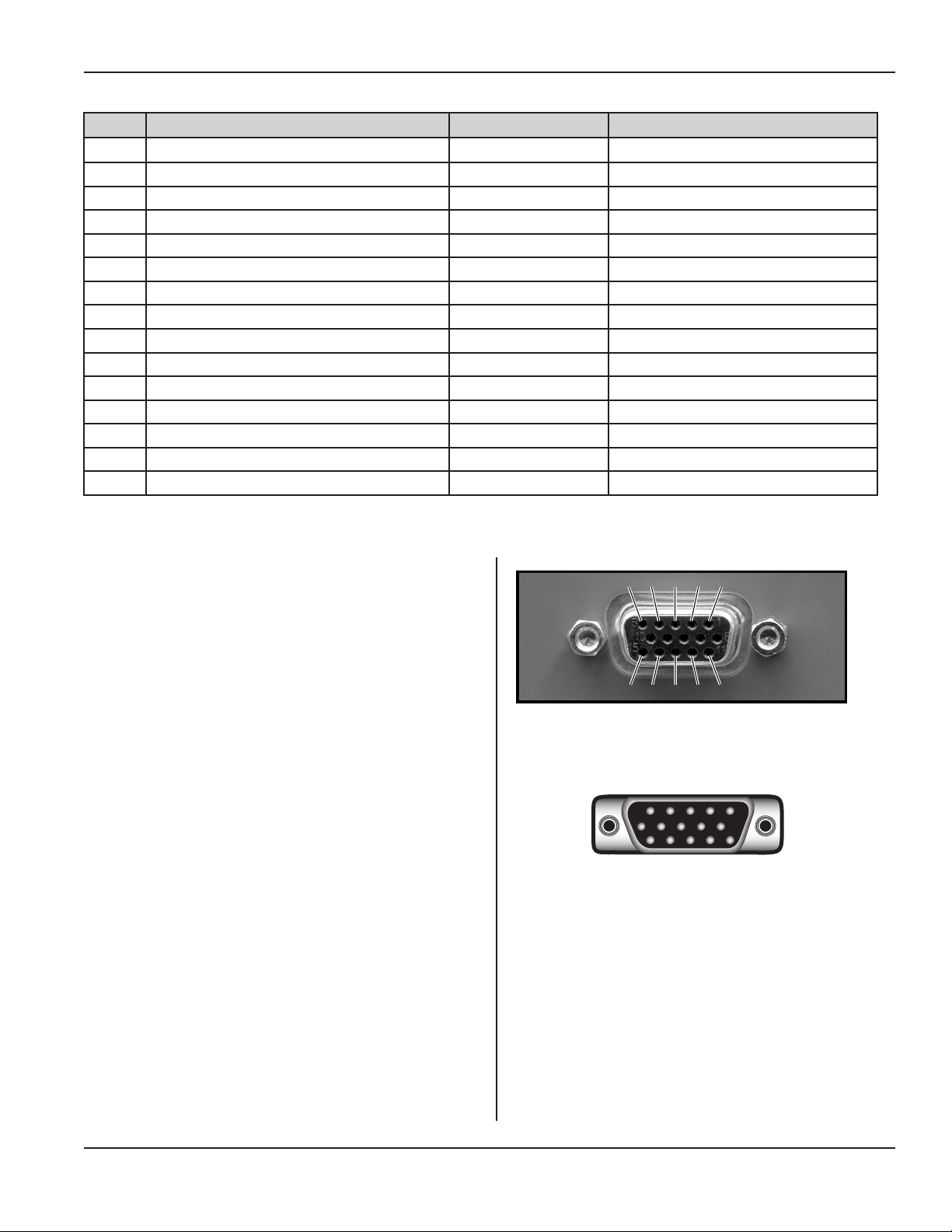
System Inputs Connector Pinout
The SYSTEM INPUTS connector is a HD-15F (high
density D-subminiature 15 circuit female) connector.
Connector pin numbers for this connector are shown in
Figure 3-7. The male connector on the cable is a mirror
image of the panel-mounted connector and is shown in
Figure 3-8. Table 3-I lists the signal names and descriptions, with more detailed descriptions that follow. The
wire color coding for the system input cable is listed in
Table 3-II, to assist with custom automation system wiring and assembly.
Figure 3-6 System I/O Panel (Standard Panel Shown)
NOTE
Refer to Section 9, Options for information
on optional features.
Continued
Page 18
Dukane Manual Part No. 403-587-00
Page 25
1 2 3 4 5
6
10
11 12 13 14 15
Section 3 - Installation
Continued from Previous Page
Pin Signal Name Cable Color Code Signal Option Requirements
1 +22VDC Power Supply BLK
2 +22VDC Power Ground WHT
3 Remote Setup Selection Bit 0 Input RED
4 Remote Setup Selection Bit 1 Input GRN
5 Remote Setup Selection Bit 2 Input ORN
6 Remote Setup Selection Bit 3 Input BLU
7 Remote Setup Selection Bit 4 Input WHT/BLK
8 Ultrasound Activation/Cycle Start Input RED/BLK
9 Not Used GRN/BLK Not Used
10 Front Panel Control Lock Input ORN/BLK Not Used
11 Press Inhibit for Hand Probes BLU/BLK Hand Probe
12 System Latch Reset Input BLK/WHT
13 Isolated Common RED/WHT
14 Not Used GRN/WHT
15 Automation Cycle Stop Input BLU/WHT
Table 3-I Generator Input Signals (J2)
System Inputs Signal Descriptions
Pin 1 (+22VDC Power Supply)
This pin can supply +22VDC at up to 250mA to power the
user’s automation controls.
Pin 2 (+22VDC Power Ground)
Pin 2 is the +22VDC return and is tied to the system chassis ground.
Pin 3 (Remote Setup Selection Bit 0 Input)
Pin 3 is the Remote Setup Selection Bit 0, which is the
least signicant bit used to select different welding setups
with an automation control system.
Pin 4 (Remote Setup Selection Bit 1 Input)
Pin 4 is the Remote Setup Selection Bit 1, which is the
second least signicant bit used to select different welding
setups with an automation control system.
5 4 3 2 1
5 4 3 2 1
10
10
15 14 13 12 11
15 14 13 12 11
Figure 3-7 HD-15F, Generator Input Connector
Figure 3-8 HD-15M, Generator Input Cable
Connector
6
6
Dukane Manual Part No. 403-587-00
Continued
Page 19
Page 26

iQ Series Ultrasonic Generator/Power Supply, Servo Systems, ES User’s Manual
Continued from Previous Page
Pin 5 (Remote Setup Selection Bit 2 Input)
Pin 5 is the Remote Setup Selection Bit 2, which is the
third least signicant bit used to select different welding
setups with an automation control system.
Pin 6 (Remote Setup Selection Bit 3 Input)
Pin 6 is the Remote Setup Selection Bit 3, which is the
second most signicant bit used to select different welding setups with an automation control system.
Pin 7 (Remote Setup Selection Bit 4 Input)
Pin 7 is the Remote Setup Selection Bit 4, which is the
most signicant bit used to select different welding setups
with an automation control system.
Pin 8 (Ultrasound Activation/ Cycle Start
Input)
Pin 8 is used to activate the generator ultrasound output.
Activation of this control input will switch the ultrasound
output ON, and deactivating this signal will switch ultrasound OFF. This input signal will also function as a cycle
start input, where the ultrasound activation and timing
are completely under the control of the process controller. Depending on the welding process controller setup,
this input signal could be activated momentarily to start
a welding cycle.
Pin 9 (Not Used)
Pin 10 (Not Used)
Pin 11 (Press Inhibit for Hand Probes)
Pin 11 is used to disconnect power applied to a press or
thruster, if a hand probe is connected to the system input
connector, for safety considerations. The hand probe activation switch could unexpectedly start a welding cycle that
activates a press or thruster to the down position. The hand
probe cable connector is wired to apply chassis ground to
this pin, when it is attached to the system, which activates
a press inhibit relay that disconnects power from the pneumatic press valves. This pin must be left open whenever
a press control board is installed. Connecting this pin to
chassis ground will inhibit press operation.
Pin 12 (System Latch Reset Input)
Pin 12 is used to reset the Any Fault or System Overload
status outputs (See Status Output descriptions). If a fault
occurs during a weld cycle, these outputs will normally
remain active until the next weld cycle is initiated. Activating this input will reset the status output faults and may
simplify automation programming.
NOTE
Refer to Latch on Bad Part, on Page 51 for
more information.
Pin 13 (Isolated Common)
Pin 13 is electrically isolated from chassis ground. Using
isolated sourcing (PNP) output drivers, this common line
would be connected to isolated ground potential. Using
isolated sinking (NPN) output drivers, this common line
would be connected to the isolated positive supply voltage
output.
Pin 14 (Not Used)
Pin 14 is an open connection.
Pin 15 (Automation Cycle Stop Input)
Pin 15 is an input control signal that when enabled, can
be used by the automation control system as a redundant
signal to shut the ultrasound output off. This signal could
also be recongured through menu selections to function
as an automation end-of-weld control signal input.
Page 20
Dukane Manual Part No. 403-587-00
Page 27
Section 3 - Installation
Pin Signal Name Cable Color Code Signal Option Requirements
1 +22VDC Power Supply BLK
2 Spare Output WHT
3 +22VDC Power Ground RED
4 Programmable Status Output 1 GRN
5 Programmable Status Output 2 ORN
6 Ultrasound Active Status Output BLU
7 Any Fault Status Output WHT/BLK
8 Press Trigger Status Output RED/BLK
9 System Overload Status Output GRN/BLK
10 System Online Status Output ORN/BLK
11 Press Top of Stroke Status Output BLU/BLK
12 Current Loop OK Status Output BLK/WHT Not Used
13 Analog Monitor Signal Common RED/WHT
14 Not Used GRN/WHT
15 Power Signal Monitor Output BLU/WHT
16 Amplitude Monitor Output BLK/RED
17 Programmable Status Output 3 WHT/RED
18 MPC Ready Status Output ORN/RED Not Used
19 System Power OK Status Output BLU/RED
20 Bad Part Status Output RED/GRN
21 Good Part Status Output ORN/GRN
22 System Ready Status Output BLK/WHT/RED
23 Suspect Part Status Output WHT/BLK/RED
24 Isolated Common RED/BLK/WHT
25 Not Used GRN/BLK/WHT
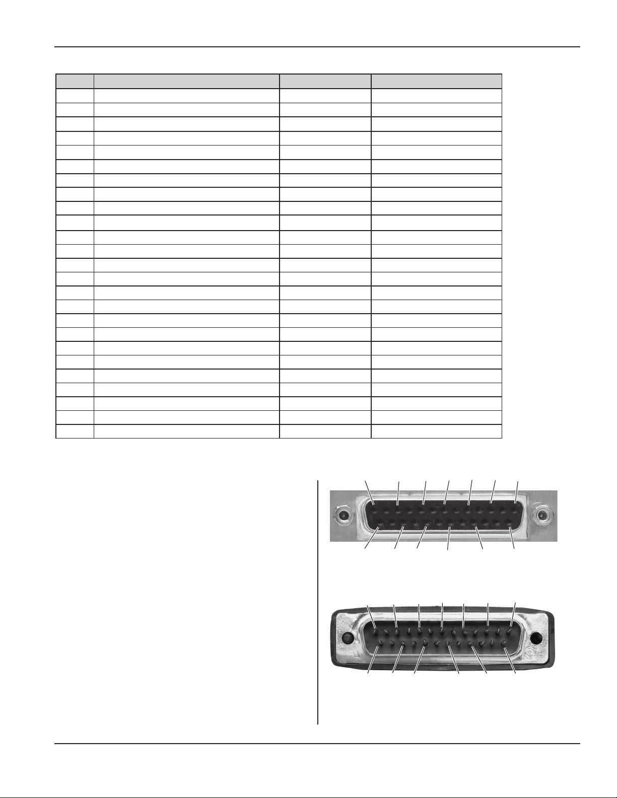
Table 3-II System Output Connector Signals (J3)
System Outputs Connector
The SYSTEM OUTPUTS connector mounted on the generator I/O panel includes connections for all of the basic
system status and monitor output signals, which will typically connect to an automated control system. The cable
attached to this connector includes all of the available
system output signals, which will be read or monitored by
a digital input card or analog inputs on the user-supplied
automation controller.
The user can determine which signals are appropriate for
each welding application.
The system monitor output signals are analog signals used
to monitor ultrasonic amplitude setting and ultrasonic output
power levels, referenced to the Monitor Common (Pin 13).
13 11 9 7 5 3 1
25 23 21 19 17 15
Figure 3–9 DB-25F, Generator Output Connector (J3)
1 3 5 7 9 11 13
15 17 19
21 23 25
Figure 3–10 DB-25M, Generator Output Cable
Connector
Continued
Dukane Manual Part No. 403-587-00
Page 21
Page 28

iQ Series Ultrasonic Generator/Power Supply, Servo Systems, ES User’s Manual
Continued from Previous Page
This is at system chassis ground potential (non-isolated).
All of the digital output status signals on this connector,
are isolated (signals are not referenced to generator chassis
ground). When a status output signal is activated, it will
sink current (500mA Max. sourced by a 24VDC supply)
to isolated common. In automation terms, the outputs are
NPN (sinking) and would drive a PNP (sourcing) input
that is referenced to the Isolated Common pin.
The digital status output signals can only sink current to
isolated common. They cannot be changed to a sourcing
(PNP) type output. If sourcing status outputs are required,
there is an optional isolated NPN to PNP conversion
module that is DIN rail mountable. The module converts
the standard isolated sinking (NPN) status output signals
to isolated sourcing (PNP) status output signals. Consult
your local sales representative for information about the
conversion module.
System Outputs Connector Pinout
The SYSTEM OUTPUTS connector is a DB-25F (standard
D-subminiature 25 circuit female) connector. Connector
pin numbers for this connector are shown in Figure 3-9.
The male connector on the cable is a mirror image of the
panel mounted connector and is shown in Figure 3-10.
Table 3-II lists the signal names. Detailed descriptions are
listed in System Outputs Signal Descriptions that follow.
To assist with custom automation system wiring and assembly, the wire color coding for the system outputs cable
is listed in Table 3-II.
System Outputs Signal Descriptions
Pin 1 (+22VDC Power Supply)
This pin can supply +22VDC at up to 250mA to power
the user’s automation controls.
Pin 2 (Not Used)
Pin 2 is an open connection.
Pin 3 (+22VDC Power Ground)
Pin 3 is the +22VDC return and is tied to the system
chassis ground.
Pin 4 (Programmable Status Output 1)
Pin 4 is a digital active low status output that can be reassigned to other system status signals. The output can
be assigned to E-STOP, Over Temperature or Servo
Error.
[The Pin 4 default output: Servo Error.]
Pin 5 (Programmable Status Output 2)
Pin 5 is a digital active low status output that can be
reassigned to other system status signals. The output
can be assigned to Hold, In Cycle, In Cycle with No
Afterburst, or Servo Home.
[The Pin 5 default output: Servo Home.]
Pin 6 (Ultrasound Active Status Output)
Pin 6 is a digital active low status output that activates
when the system is delivering ultrasonic power to the load
attached to the ultrasound output connector. This output
will be an open circuit when the ultrasound output is off.
Pin 7 (Any Fault Status Output)
Pin 7 is a digital active low status output that activates
whenever any fault condition is detected that inhibits ultrasound output and normal system operation. This output
will be an open circuit when no system fault conditions
are detected.
Generator faults that will activate the Any Fault output:
• Overload (Average, Peak, or Frequency)
• Overtemperature Fault
• System Power Fault
Page 22
Continued
Dukane Manual Part No. 403-587-00
Page 29

Continued from Previous Page
Section 3 - Installation
Pin 8 (Press Trigger Status Output)
Pin 8 is a digital active low status output that activates
when the specied trigger type has occurred. It will remain
active until the thruster head raises to the top of the stroke.
This output will be an open circuit when a trigger condition
hasn’t been detected.
Pin 9 (System Overload Status Output)
Pin 9 is a digital active low status output that activates
whenever any overload condition is tripped. Activation
of the overload status output signal could be caused by an
average overload, a positive peak overload or a negative
peak overload condition. After the overload status output
activates, it will remain active until the next ultrasound
activation cycle begins and this output will automatically
reset. This output will be an open circuit when no overload
conditions have been detected.
Pin 10 (System On-Line Status Output)
Pin 10 is a digital active low status output that activates
when the system is in the ON LINE operating mode, which
enables the activation of the ultrasonic output. This output
will be an open circuit if the system is switched to the OFF
LINE operating mode, which will prevent the start of a
welding cycle or activation of the ultrasound output. Note
that an automation controlled process can not weld any
parts, if the system is, accidentally or otherwise, switched
to the OFF LINE operating mode.
Pin 11 (Press Top of Stroke Status Output)
Pin 14 (Not Used)
Pin 14 is connected to the system chassis ground.
Pin 15 (Power Signal Monitor Output)
Pin 15 is an analog output signal used to monitor the power
output from the welding system. The scaling on this output
signal is as shown below:
15kHz, 20kHz, 30kHz and 40kHz systems
1 Watt = 0.001 VDC (1mV per Watt)
50kHz and higher systems
1 Watt = 0.010 VDC (10mV per Watt)
Examples: 20kHz system measures 0.525 VDC on
Power Monitor Output = 525 Watts
50kHz system measures 0.525 VDC on
Power Monitor Output = 52.5 Watts
Pin 16 (Amplitude Monitor Output)
Pin 16 is an analog output signal used to monitor the
system amplitude setting. The scaling on this output signal is 100% amplitude = 10.0 VDC, or 0.1 VDC per 1%
amplitude. This monitor signal output would typically
be used when a remote control option board is installed
in the system. The automation control system will adjust
the system’s amplitude setting remotely, using a 4-20mA
current loop attached to the input of the remote control
board. Using this monitor output, the control system can
verify that the amplitude is set to the expected programmed
amplitude level.
Pin 11 is a digital active low status output that activates
when the press/thruster head is in the top of stroke position. This output will be an open circuit when the press/
thruster head is not at the top of stroke position.
Pin 12 (Not Used)
Pin 13 (Analog Monitor Signal Common)
Pin 13 is the signal common (ground) connection for all
of the analog monitor signals (on Pins 15 and 16). This
signal common pin is connected to system chassis ground
and is not isolated from the generator chassis. This is an
analog signal ground connection. Do not connect anything
to this ground connection, except the wiring to the inputs
of the analog instrumentation devices used to measure the
monitor output signals.
Dukane Manual Part No. 403-587-00
Continued
Page 23
Page 30

iQ Series Ultrasonic Generator/Power Supply, Servo Systems, ES User’s Manual
Continued from Previous Page
Pin 17 (Programmable Status Output 3)
Pin 17 is a digital active low status output that activates
when the system is regulating the amplitude level correctly. This output becomes an open circuit when the
system falls out of regulation. When that happens, it can-
not adjust the system output to the output level that was
programmed as the regulation set point.
This signal will be activated at the end of the ramp-up
time until the beginning of the ramp-down time. This
status signal will be active for the time the ultrasound is
at the programmed amplitude setting.
The output can be assigned to Amplitude Regulation
Status, Servo Error Status, Home Servo Status or
Teaching Status.
[Pin 17 default output: Amplitude Regulation Status.]
Pin 18 (Not Used)
Pin 19 (System Power OK Status Output)
Pin 19 is a digital active low status output that activates
when no fault conditions are detected by any of the power
fault detection circuits included in the system. This output
will be an open circuit when any power related fault is
detected in the system.
Pin 20 (Bad Part Status Output)
Pin 20 is a digital active low status output that activates,
either momentarily or until the start of the next welding
cycle, when the welding parameters recorded during the
previous welding cycle are outside of the programmed
bad part limits. This output will be an open circuit when
a bad part has not been detected.
Pin 21 (Good Part Status Output)
This status output signal will activate only when the system
is ready to activate ultrasound or begin a weld cycle. Pin
22 is a digital active low status output that activates when
a weld processing cycle is completed and the welding
process control system is ready to start the next welding
cycle. This output will be an open circuit when the welding
process controller determines that the next welding cycle
cannot be started. This includes system faults or off line
active, but not a process fault like Overload.
Pin 23 (Suspect Part Status Output)
Pin 23 is a digital active low status output that activates,
either momentarily or until the start of the next welding
cycle, when the welding parameters recorded during the
previous welding cycle are outside of the programmed
suspect part limits. This output will be an open circuit after
a welding cycle when a suspect part has not been detected.
Pin 24 (Isolated Common)
Pin 24 is electrically isolated from chassis ground. This
common line should be connected to negative output at a
user-provided isolated 24VDC power supply. The isolated
NPN status output signals can drive PNP inputs.
Pin 25 (Not Used)
Pin 25 is an open connection.
Pin 21 is a digital active low status output that activates,
either momentarily or until the start of the next welding
cycle, when the welding parameters recorded during the
previous welding cycle do not exceed the programmed
suspect or bad part limits. This output will be an open
circuit after a welding cycle when either a suspect or bad
part has been detected.
Pin 22 (System Ready Status Output)
Page 24
Dukane Manual Part No. 403-587-00
Page 31
Earth
Ground
#14 Gauge
Stranded or
Solid Wire
Fixed Probe Mount
or 2nd Chassis
Grounding Stud
3rd Chassis
Grounding
Stud
Chassis Grounding
Stud
Recommended protective
earth ground connection
wire color: green or green
with yellow stripe.
Section 3 - Installation
RFI Grounding
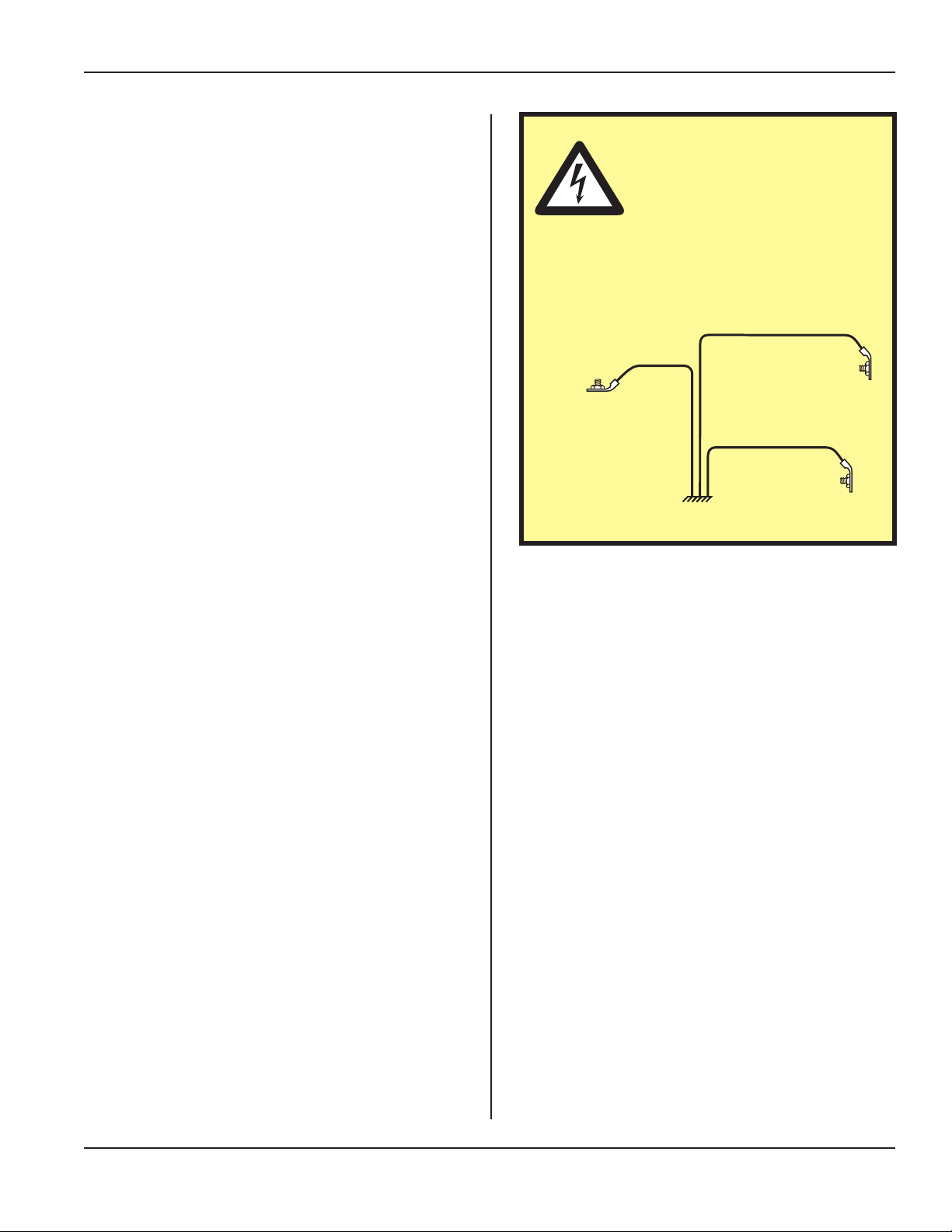
The iQ Series generator provides the operating power
and power returns. Make sure the generator is grounded
properly.
In addition to the safety considerations, proper grounding
is essential for the effective suppression of RFI (Radio
Frequency Interference). Every generator contains a
RFI lter which blocks noise on the AC power line from
entering the generator control circuitry. This lter also
prevents ultrasonic RFI from being fed back into the AC
power line.
If you experience problems with RFI from the press, run
an additional grounding wire from the press base grounding stud to the nearest grounded metal pipe or equivalent
earth ground by means of a ground clamp. Use at least 14
AWG wire for the connection to the press base.
CAUTION
To minimize electrical noise
and eliminate ground currents, ground the chassis
as shown. Use a STAR conguration (illustrated below).
Do not DAISY CHAIN the
grounds.
Dukane Manual Part No. 403-587-00
Page 25
Page 32
iQ Series Ultrasonic Generator/Power Supply, Servo Systems, ES User’s Manual
Connector Descriptions
iQ Generator Connectors
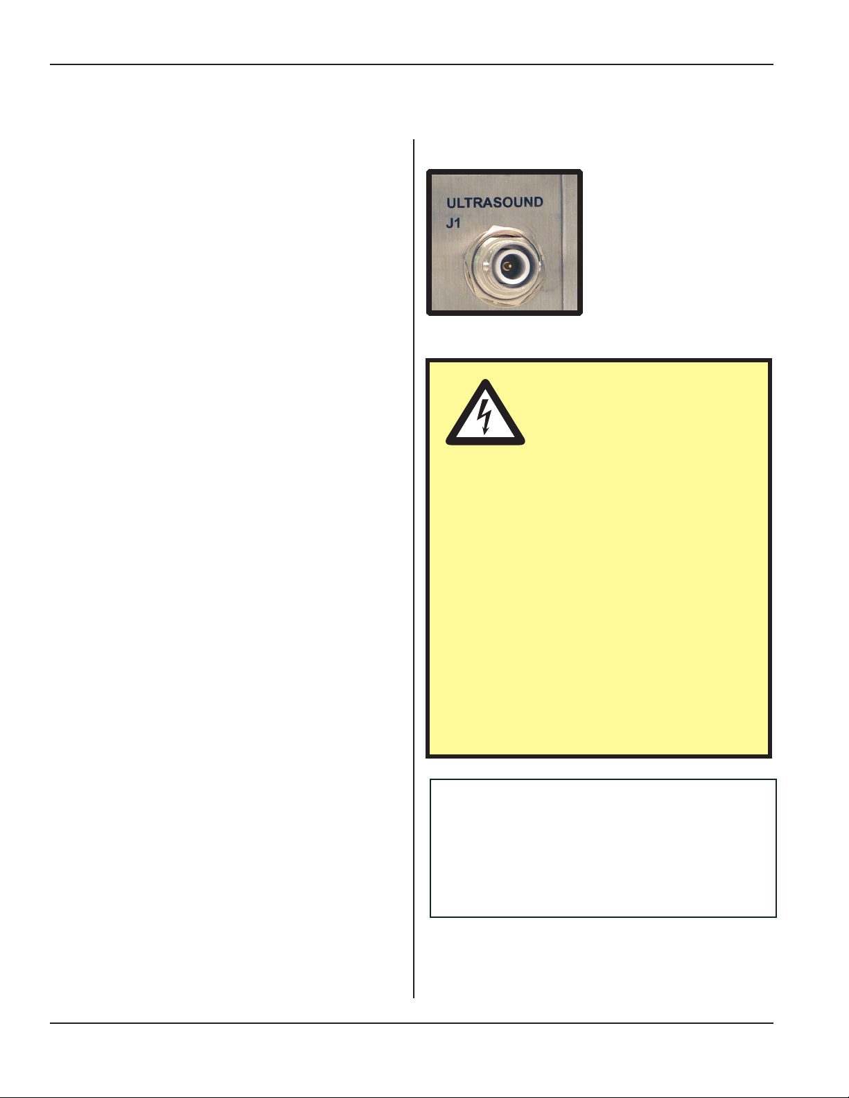
J1 - Ultrasound Output Connector
The ultrasound output connector used with all standard generators is a high voltage (5000V) coaxial style
SHV-BNC connector. This connector provides superior shielding of electrical noise, compared to other
types of connectors. The ultrasound output connector
mates with fully shielded coaxial ultrasound cables
that are secured with a simple and reliable quarter-turn
bayonet style attachment mechanism.
J2 - System Inputs Connector
The SYSTEM INPUTS connector includes connections for all of the basic system control input signals
that will typically come from an automated control
system. The cable attached to this connector includes
all of the available system control signals, which will
be controlled by an output card or output port on the
automation controller.
The user can determine which signals to use for each
particular welding application, but there must be at
least one connection to this connector in order to
activate the ultrasound output.
J3 - System Outputs Connector
The SYSTEM OUTPUTS connector includes connections for all of the basic system status and monitor
output signals, which will typically connect to an
automated control system. The cable attached to this
connector includes all of the available system output
signals, which will be read or monitored by a digital
input card or analog inputs on the user-supplied automation controller.
Figure 3-11 Ultrasound Output Connector
very high AC voltage (1200VAC). At high
power levels this can exceed 2 amperes of
current and must be securely terminated
via the ultrasound cable for safe operation.
Use original equipment ultrasound cables
for safe and reliable system operation. Improperly assembled ultrasound cables can
result in high voltage arcing and will destroy
the ultrasound connectors.
Do not use your generator if there is any
evidence of arcing (black carbon deposits)
on either the ultrasound output connector or
the ultrasound cable connectors.
CAUTION
The ultrasonic output from
this connector (that drives the
attached ultrasonic load) is a
The user can determine which signals are appropriate
for each welding application.
Page 26
NOTE
For details on integrating the welder with
automation, refer to Application Note
AN507 (Automation Interface Guidelines)
at www.dukane.com/us > Downloads >
Application Notes.
Continued
Dukane Manual Part No. 403-587-00
Page 33
Continued from Previous Page
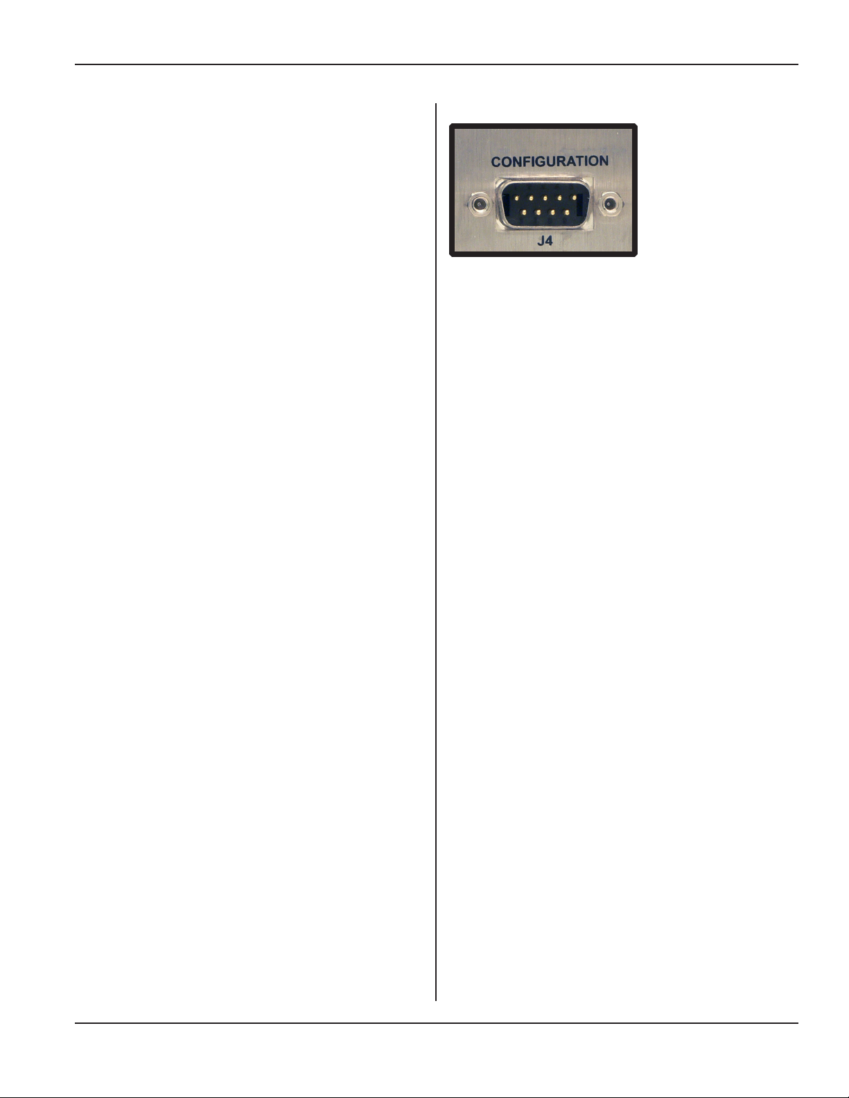
J4 - Conguration Port Connector
The conguration port connector is a DB-9M (standard D-subminiature 9 circuit male) typically used
for RS-232 serial communications. This serial port
(DTE) connects to a serial port (DCE) on a computer
via a standard 9- pin serial cable. If the computer does
not have a serial port, you may use a USB-to-serial
conversion cable.
Section 3 - Installation
This port is used for eld updates to the generator
rmware, without removing the enclosure cover.
This port can also be used with a software application running on a Windows PC to modify the factory
default system settings and hardware congurations.
Contact your local sales representative for software
availability information and access to documentation
that will allow you to make use of the conguration
port features.
J6 - Base/Abort
The Base/Abort connector accepts the operate and
emergency stop signals from the optical operate
switches and abort switch on the base. If you are
using custom automation, you may have separate
operate and abort switches, but these still connect to
this connector on the generator.
J9 - Ethernet
This port is used for Ethernet communication
between the generator and HMI running iQ
Explorer II software.
Figure 3-12 Conguration Port Connector
J10 - RS-232
This port is primarily used for welder diagnostic
functions accessible via serial communication to
a PC. Guidance will be provided by Dukane if the
need to use the capability arises.
J11 - Encoder
This connector accepts signals from the distance
encoder on the press.
J5 – Thruster
This connector is used to interface various control
signals between the press and generator.
Dukane Manual Part No. 403-587-00
Page 27
Page 34
iQ Series Ultrasonic Generator/Power Supply, Servo Systems, ES User’s Manual
Power Cords
The AC line cords supplied with the standard generators
are matched to the ultrasonic output power rating and the
continent of specied use. See Table 3-III.
ceptacle is encountered, we strongly
recommend that it is replaced with a
properly grounded three-lead recep-
tacle.
Have a qualified electrician do the
replacement in accordance with the
National Electrical Code and local codes
and ordinances. DO NOT cut off the
power cord grounding prong or alter the
plug in any way.
CAUTION
The power cord is equipped
with a three-prong, grounded-type plug for your safety.
Whenever a two-slot re-
Continent of Use Power Cord
Part Number
200 - 1110 240V, 15A
North America
200 - 1541 240V, 10A
200 - 1111 240V, 16A
Continental Europe
200 - 1542 240V, 10A
Table 3-III Power Cords
Power
Page 28
Dukane Manual Part No. 403-587-00
Page 35
Cable Connections
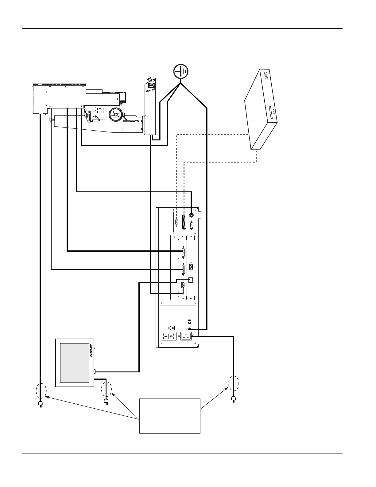
The iQ Servo Presses are congured in one of two ways,
depending on the model. Each has unique cabling require-
ments.
Section 3 - Installation
Version 1- Remote Controller
Conguration
(Press Models: 43S215, 43S245-AX)
Typical Components:
• iQ Generator
• iQ Servo Press
• Remote Controller (contains servo electronics)
• HMI Interface (optional on some systems)
• Customer Automation Equipment
Connect the Cables
Use the following references as guides to making the
connections:
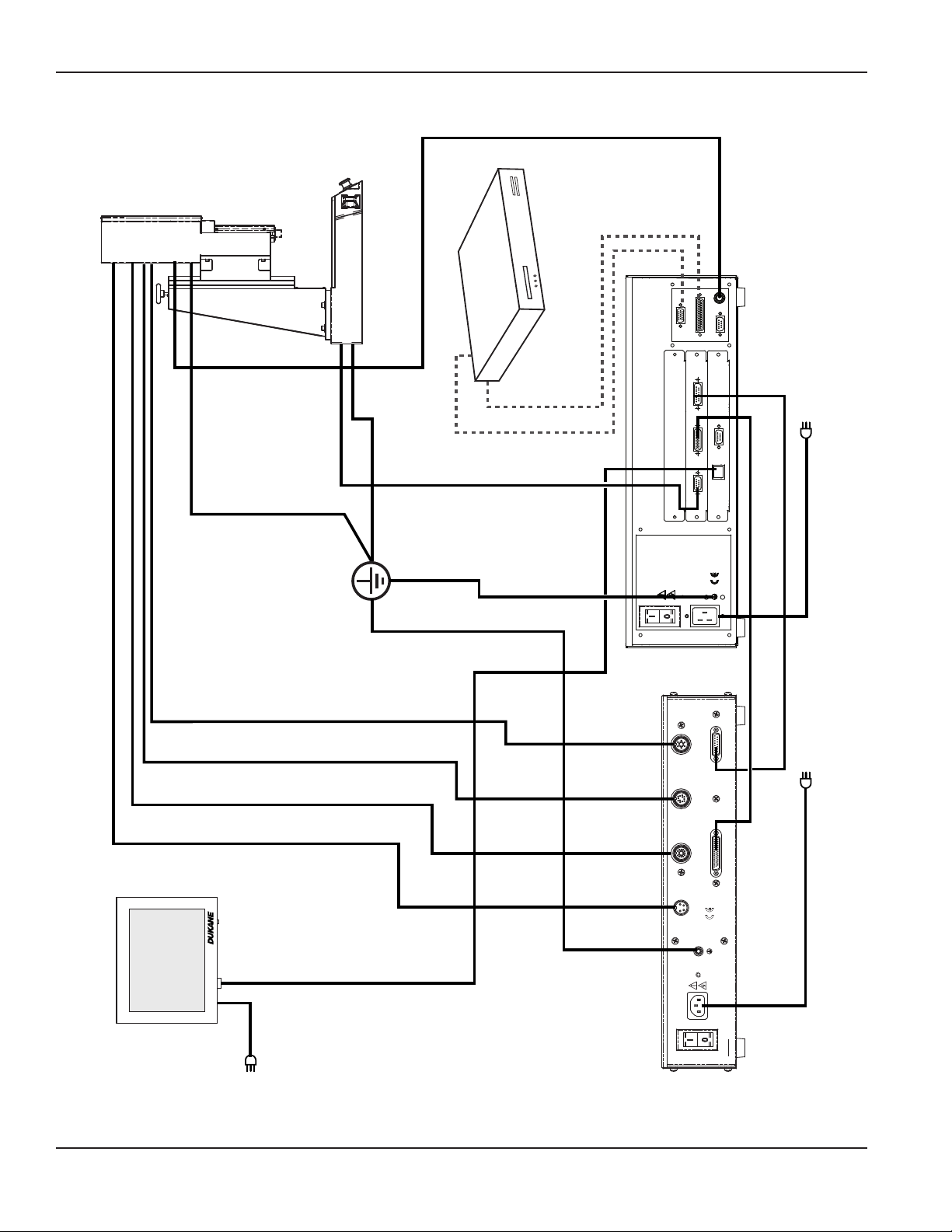
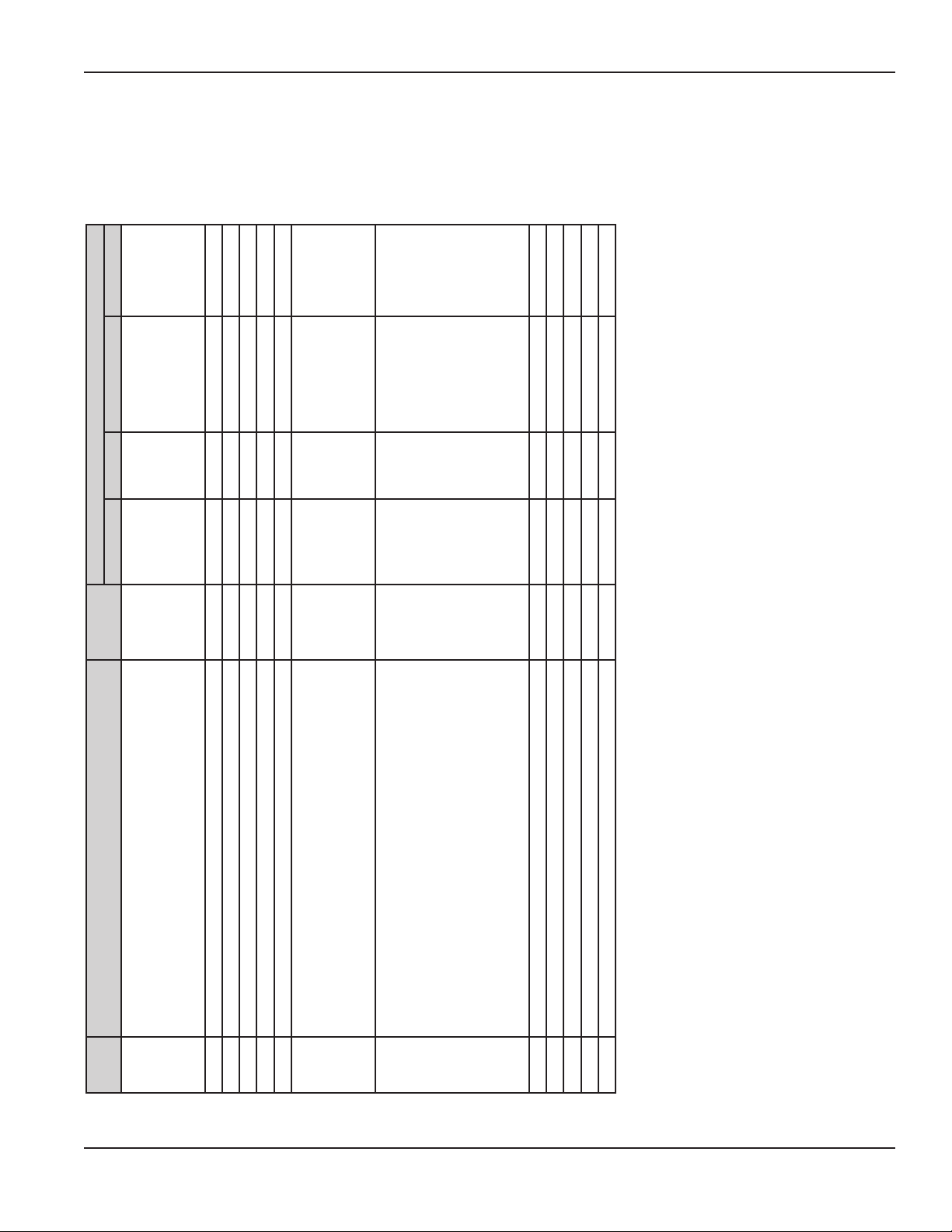
For press model 43S215, use Figure 3-13 and Table
3-IV.
For press models 43S245-AX, use Figure 3-13 and
Table 3-V.
1. Make the basic cable connections 1 through 9, and
13-16.
2. Make any optional connections.
3. Connect any customer-supplied equipment such as
automation. Use cables 17 and 18 for automation.
4. Connect customer-supplied electricity using cables
10, 11, and 12.
Connect the power cords last, but do not turn on the
power yet.
CAUTION
Before connecting or
disconnecting cables:
Put power switches for
the iQ generator, press,
remote controller, and any usersupplied automation equipment in
the OFF position. Turn off electrical
power. Remove AC power cords
from their receptacles.
NOTE
Some connectors have a pair of
threaded jack screws to secure the
connector. Make sure the screws are
snug, but do not overtighten them.
CAUTION
DO NOT operate the
generator unless the
ultrasound coaxial ca-
ble is connected and
the transducer is installed in the
thruster. Otherwise, an overload
condition could occur, with possible damage to the generator.
5. Recheck all connections. When they are secure, you
are ready to connect electrical power.
6. Finally, connect electrical power. See Section 11,
Specications for AC power requirements.
Dukane Manual Part No. 403-587-00
Continued
Page 29
Page 36
iQ Series Ultrasonic Generator/Power Supply, Servo Systems, ES User’s Manual
Continued from Previous Page
Servo Press/Thruster (Version 1)
Automation Equipment
17
SYSTEM INPUTS
J2
18
SYSTEM OUTPUTS
5
ULTRASOUND
J1
J3
J4
CONFIGURATION
13
MUST BE GROUNDED.
DISCONNECT LINE POWER
BEFORE REMOVING COVER.
1 2 3 4
J11 ENCODER
J10 RS-232
J5 THRUSTER
J9
ETHERNET
J6 BASE/ABORT
DUKANE CORP
U.S. PATENT 5,880,580
OTHER PATENTS PENDING
ST. CHARLES IL 60174
MADE IN U.S.A.
PE
200-240 Vac
50/60Hz, 15A
LINE VOLTAGE:
K
C
T
U
BA
O
D
R
E
EE
205
D
F
J
O
O
V
NC
R
E
SE
N
I
R
E
D
204
J
O
NC
E
O
O
I/
I/
R
R
O
E
T
T
A
206
S
J
R
E
RU
N
H
E
T
G
N
O
R
I
E
T
W
L
.
I
RA
,
O
.A
O
S
P
.
ES
100
P
U
L
J
O
R
R
N
V
A
I
O
R
H
E
C
C
D
A
SE
E
M
ST.
KAN
U
D
PE
.
D
E
D
N
U
O
R
G
BE
ST
E:
A
U
G
0
M
A
1
Vac
T
LT
E
0
Hz,
O
24
TL
V
0
6
U
0
/
E
9
0
O
N
5
I
E
L
N
I
L
R
E
W
O
P
:
G
N
I
N
R
A
W
7
12
201
J
10
6
202
J
WW.DUKA NE.COM
W
R.
E
V
O
C
G
N
I
V
O
M
E
R
E
R
O
F
E
B
R
E
W
O
P
E
N
I
L
T
C
NE
N
O
C
IS
D
14
8
-WARNING-
POWER LINE OUTLET
Earth
Ground
16
15
9
11
Figure 3-13 iQ Generator, Remote Controller, and Servo Press/Thruster Connections (Version 1)
Page 30
Dukane Manual Part No. 403-587-00
Continued
Page 37
HMI
Section 3 - Installation
Continued from Previous Page
Servo Press/Thruster (Version 1)
Remote
Controller
Connections
Generator Base Thruster
Length
(meters)
J205 -
SERVO
FEEDBACK
2.4 - - - AC INPUT -
2.4 - - - - AC INPUT
2.4 AC INPUT - - - -
Part Number
One of the following:
200-1110 (240 VAC, 15A, US)
200-1111 (240 VAC, 16A, Europe)
200-1612 (240 VAC, 15A, India)
One of the following:
200-1541 (240 VAC, 10A, US)
200-1542 (240 VAC, 10A, Europe)
200-1624 (240 VAC, 10A, India)
200-1576 (120 VAC)
(Power cord is integral to
generator,)
1 200-1655-XXM XX - - SERVO POWER J100 -
2 200-1647-XXM XX - - THRUSTER I/O J206 -
3 200-1648-XXM XX - - ENCODER J204 -
4 200-1649-XXM XX - -
5 200-1289-XXM XX J1 - ULTRASOUND - -
6 200-1556-XXM XX J5 - - J202 -
7 200-1613-XXM XX J11 - - J201 -
8 200-1545-XXM XX J6 J35 - - -
No.
Cable
9 200-1553-XXM XX J9 - - - ETHERNET
10
11
12
13 200-1557 5 - - PE - -
14 200-1557 5 - GRND - - -
15 200-1557 5 - - - PE -
16 200-1557 5 PE - - - -
17 200-1380-XXM XX J2 - - - -
18 200-1381-XXM XX J3 - - - -
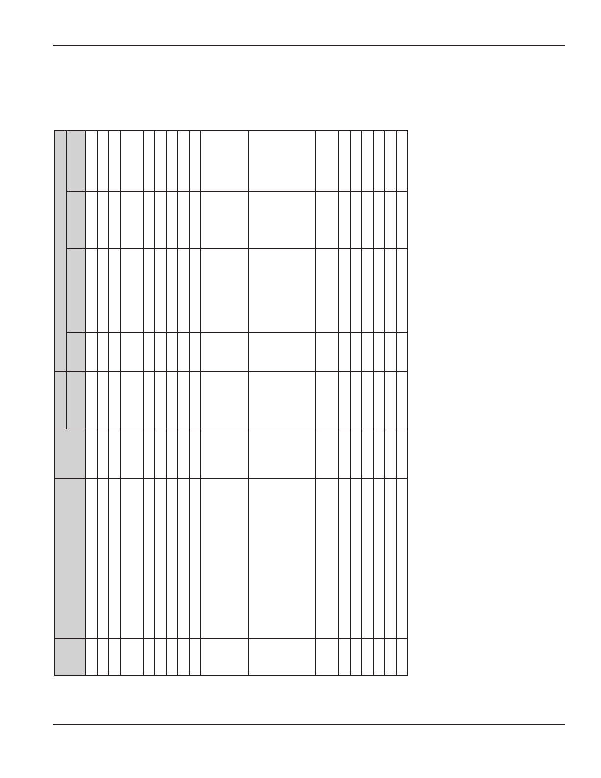
Table 3-IV iQ Generator, Remote Controller, and Servo Press/Thruster Cables for Press Model 43S215
Dukane Manual Part No. 403-587-00
Continued
Page 31
Page 38

iQ Series Ultrasonic Generator/Power Supply, Servo Systems, ES User’s Manual
Continued from Previous Page
Servo Press/Thruster (Version 1)
HMI
Remote
Controller
Connections
Generator Base Thruster
Length
(meters)
J205 -
SERVO
FEEDBACK
2.4 - - - AC INPUT -
2.4 - - - - AC INPUT
2.4 AC INPUT - - - -
Part Number
One of the following:
200-1541 (240 VAC, 10A, US)
200-1542 (240 VAC, 10A, Europe)
200-1624 (240 VAC, 10A, India)
200-1576 (120 VAC)
One of the following:
200-1541 (240 VAC, 10A, US)
200-1542 (240 VAC, 10A, Europe)
200-1624 (240 VAC, 10A, India)
200-1576 (120 VAC)
One of the following:
200-1110 (240 VAC, 15A, US)
200-1111 (240 VAC, 16A, Europe)
200-1612 (240 VAC, 15A, India)
200-1541 (240 VAC, 10A, US)
200-1542 (240 VAC, 10A, Europe)
200-1624 (240 VAC, 10A, India)
(for 120 VAC models, power cord
is integral to generator)
1 200-1646-XXM XX - - SERVO POWER J100 -
2 200-1647-XXM XX - - THRUSTER I/O J206 -
3 200-1648-XXM XX - - ENCODER J204 -
4 200-1649-XXM XX - -
5 200-479-XXM XX J1 - ULTRASOUND - -
6 200-1556-XXM XX J5 - - J202 -
7 200-1613-XXM XX J11 - - J201 -
8 200-1545-XXM XX J6 J35 - - -
No.
Cable
9 200-1553-XXM XX J9 - - - ETHERNET
10
11
12
13 200-1557 5 - - PE - -
14 200-1557 5 - GRND - - -
15 200-1557 5 - - - PE -
16 200-1557 5 PE - - - -
Table 3-V iQ Generator, Remote Controller, and Servo Press/Thruster Cables for Press Models 43S245-AX
Page 32
Dukane Manual Part No. 403-587-00
17 200-1380-XXM XX J2 - - - -
18 200-1381-XXM XX J3 - - - -
Page 39
Cable Connections Continued
Version 2 - Integrated Conguration
(Press Models: 43S220, 43S340)
Section 3 - Installation
Typical Components:
• iQ Generator
• iQ Servo Press with Integrated Servo Electronics
• HMI Interface (optional on some models)
• Customer Automation Equipment
Connect the Cables
Use Figure 3-14 and Table 3-VI as guides to making the
connections.
1. Make the basic cable connections 2 through 6, and
9-11.
2. Make any optional connections.
3. Connect any customer-supplied equipment such as
automation. Use cables 12 and 13 for automation.
4. Connect customer-supplied electricity using cables 1,
7, and 8.
Read and follow the NOTE about cable layout to the right.
CAUTION
Before connecting or dis-
connecting cables: Put
power switches for the iQ
generator, press and any
user-supplied automation equipment
in the OFF position. Turn off electrical
power. Remove AC power cords from
their receptacles.
NOTE
Arrange the cable layout so that cable 1
is physically separated from other cables
connected to the thruster (see Figure
3-14). Do not bundle cables 1, 7, or 8 with
any other cables.
Connect the power cords last, but do not turn on the
power yet.
5. Recheck all connections. When they are secure, you
are ready to connect electrical power.
6. Finally, connect electrical power. See Section 11,
Specications for AC power requirements.
CAUTION
DO NOT operate the
generator unless the ultrasound coaxial cable is
connected and the transducer is installed in the thruster.
Otherwise, an overload condition
could occur, with possible damage
to the generator.
Continued
Dukane Manual Part No. 403-587-00
Page 33
Page 40
iQ Series Ultrasonic Generator/Power Supply, Servo Systems, ES User’s Manual
Continued from Previous Page
Servo Press/Thruster (Version 2)
Earth
Ground
10
9
13 12
4
Automation Equipment
ULTRASOUND
J1
J3
-WARNING-
POWER LINE OUTLET
MUST BE GROUNDED.
DISCONNECT LINE POWER
BEFORE REMOVING COVER.
SYSTEM INPUTS
200-240 Vac
LINE VOLTAGE:
J2
50/60Hz, 15A
SYSTEM OUTPUTS
J11 ENCODER
J5 THRUSTER
J6 BASE/ABORT
CONFIGURATION
J10 RS-232
J9
DUKANE CORP
U.S. PATENT 5,880,580
ST. CHARLES IL 60174
MADE IN U.S.A.
PE
J4
11
ETHERNET
OTHER PATENTS PENDING
5
3
2
6
8
1
7
NOTE:
Separate
cables 1, 7
and 8 from
other cables.
DO NOT
bundle these
with other
cables.
Figure 3-14 iQ Generator and Servo Press/Thruster Connections (Version 2)
Page 34
Continued
Dukane Manual Part No. 403-587-00
Page 41
Connections
Section 3 - Installation
Continued from Previous Page
Servo Press/Thruster (Version 2)
Generator Base Thruster HMI
Length
(meters)
Part Number
2.4 - - AC INPUT -
2.4 - - - AC INPUT
2.4 AC INPUT - - -
One of the following:
200-1541 (240 VAC, 10A, US)
200-1542 (240 VAC, 10A, Europe)
200-1624 (240 VAC, 10A, India)
No.
Cable
200-1576 (120 VAC)
1
2 200-1556-XXM XX J5 - THRUSTER I/O -
3 200-1613-XXM XX J11 - ENCODER -
4 200-479-XXM XX J1 - ULTRASOUND -
One of the following:
200-1541 (240 VAC, 10A, US)
200-1542 (240 VAC, 10A, Europe)
5 200-1545-XXM XX J6 J35 - -
6 200-1553-XXM XX J9 - - ETHERNET
7
200-1624 (240 VAC, 10A, India)
200-1576 (120 VAC)
One of the following:
200-1110 (240 VAC, 15A, US)
200-1111 (240 VAC, 16A, Europe)
200-1612 (240 VAC, 15A, India)
200-1541 (240 VAC, 10A, US)
200-1542 (240 VAC, 10A, Europe)
200-1624 (240 VAC, 10A, India)
(for 120 VAC, 3600 W, or 4800 W models, power cord is
8
integral to generator)
9 200-1557 5 - - PE -
10 200-1557 5 - GRND - -
Table 3-VI iQ Generator and Servo Press/Thruster Cables (Version 2)
Dukane Manual Part No. 403-587-00
11 200-1557 5 PE - - -
12 200-1380-XXM XX J2 - - -
13 200-1381-XXM XX J3 - - -
Page 35
Page 42
iQ Series Ultrasonic Generator/Power Supply, Servo Systems, ES User’s Manual
Networking
Where several welders are connected, please refer to the
iQ Explorer II User's Manual, 403-585-00. Refer to the
Section on networking.
Among other things, there is information about connection
through:
• a stand-alone network, and
• a local area network.
Recheck Connections
Recheck all cabling connections for the:
• iQ ES Generator
• Remote Controller
• Press/Thruster
• Connections to Local Area Network
Connect AC Power
When all cabling connections have been made, and they
have been systematically rechecked, connect AC line power
to your system.
WARNING
Any modications to the
Activation Switch (also
known as the Operate
Switch) circuit must
comply with all OSHA and ANSI
requirements. Compliance with all
local building and electrical codes
is also required.
Dukane Corporation does not as-
sume any responsibility or liability
for circuitry modications made by
the customer or by any third party
manufacturer.
WARNING
Any modifications to the
Emergency Stop Switch (also
known as the E-STOP or Abort
Switch) circuit must comply
with all OSHA and ANSI requirements.
Compliance with all local building and
electrical codes is also required.
Page 36
Dukane Corporation does not assume
any responsibility or liability for circuitry modications made by the customer
or by any third party manufacturer.
Dukane Manual Part No. 403-587-00
Page 43

Section 4 - Control Panel
SECTION 4
Control Panel
Overview...................................39
System Operating Mode Keys ..................40
Navigation Keys . . . . . . . . . . . . . . . . . . . . . . . . . . . . . 41
System Power Output Level....................42
Screen Basics...............................43
Dukane Manual Part No. 403-587-00
Page 37
Page 44

iQ Series Ultrasonic Generator/Power Supply, Servo Systems, ES User’s Manual
This page intentionally left blank
Page 38
Dukane Manual Part No. 403-587-00
Page 45
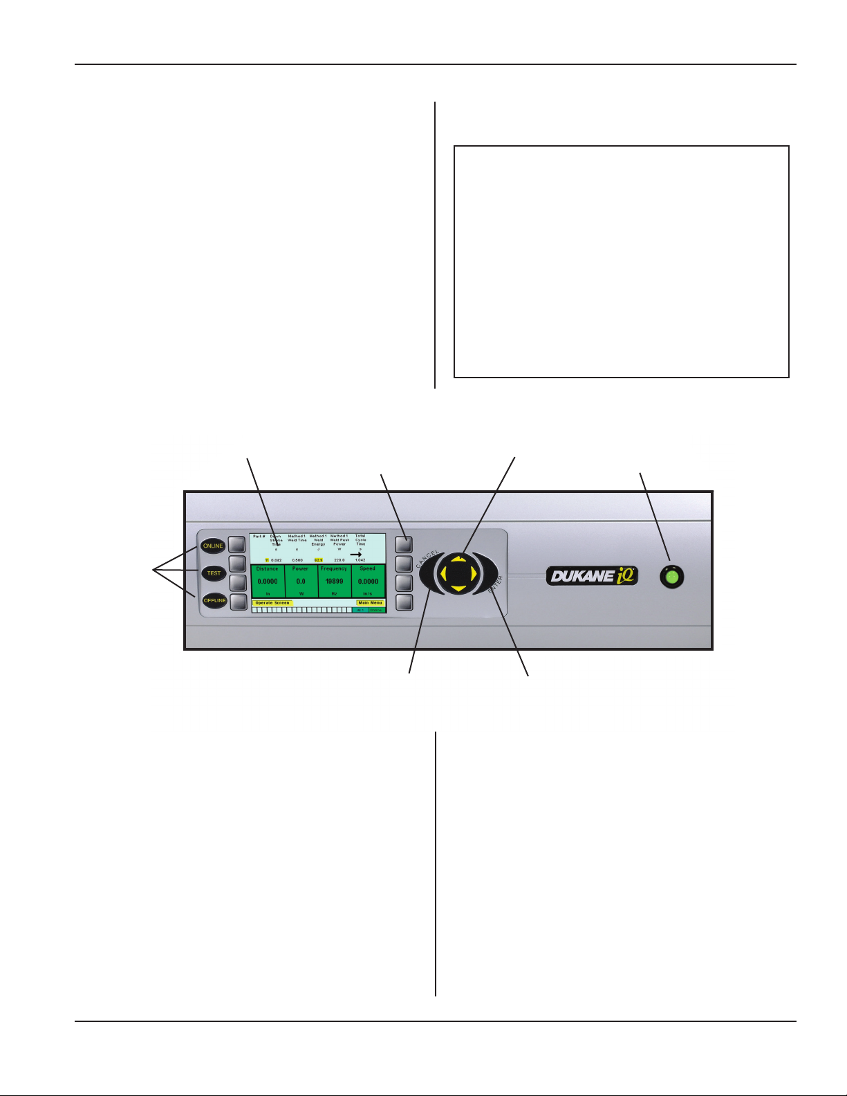
Overview
This section introduces the iQ Series ultrasonic generator
Section 4 - Control Panel
ES control panel and color display with this information:
• FunctionsofthepanelcomponentsshowninFigure
4-1belowarediscussed.
• Somescreenbasicsareintroduced:
— Making selections,
—Interpretingonscreenarrows,
— Using the virtual keyboard feature, and
—Takingalookatsetupidentication.
Color Display
Soft Keys (8)
System
Operating
Mode
Keys (3)
NOTE
Do not touch the display. Touch only
the System Operating Mode Keys, the
Navigation Keys and the Soft Keys to
the left and right of the display.
Cleaning - If the display is dirty, clean it
by rst putting a mild cleaning solution
on a clean, soft cloth. Then, gently wipe
the cloth over the screen.
Navigation Keys (4)
Lighted Power Indicator
CANCEL Key
Figure 4-1 iQ Generator Display and Control Keys
Dukane Manual Part No. 403-587-00
ENTER Key
Page 39
Page 46
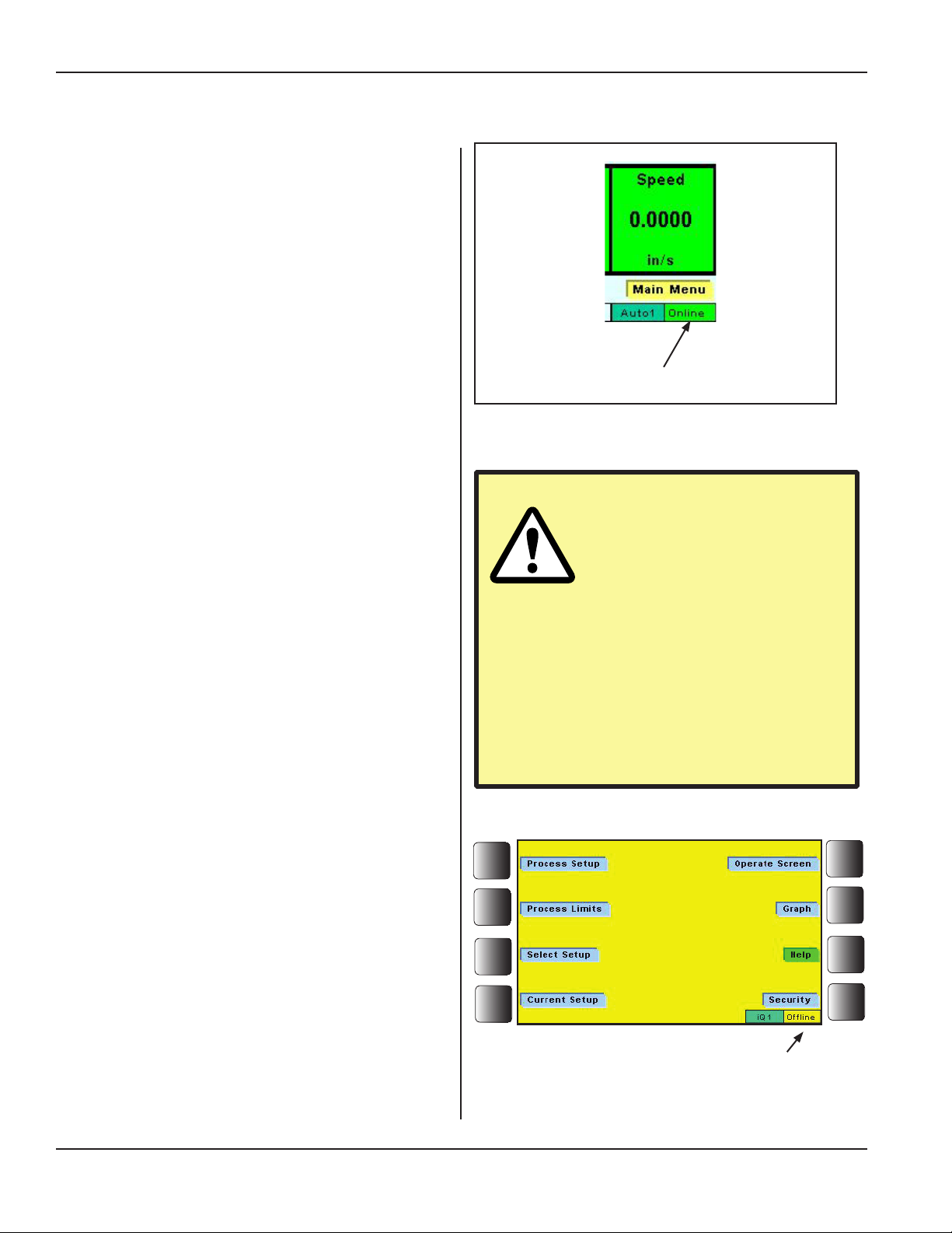
iQ Series Ultrasonic Generator/Power Supply, Servo Systems, ES User’s Manual
System Operating Mode Keys
ON LINE - After AC power has been activated and the
generator is operating normally, ON LINE is the normal
operating mode. The generator can produce ultrasound
signals in this mode.
The display has a WHITE background and the word,
Online appears in a GREEN box in the display's lower
right corner.
TEST - After AC power has been activated and the gen-
erator is operating normally, in the ON LINE mode, the
TEST key can be pushed.
This activates a momentary ultrasound pulse allowing
the operator to test system function. The display will
show the real time settings for Amplitude, Power (does
notappearwithTimeOnlygenerators), and Operating
Frequency.
This information is useful in troubleshooting.
OFFLINE - After AC power has been activated and the
generator is operating normally, the OFFLINE key may
be pressed to put the generator into the ofine mode. In
this mode the generator can not generate an ultrasound
signal.
The display has a YELLOW background, and the word,
Ofine appears in a yellow box in the lower right corner
of the display. See Figure 4-3 to the right.
Operating Mode Indicator
Online (green); Ofine (yellow); or E-STOP (red)
Figure 4-2 Display Detail, Operating Mode Indicator
If a transducer is not connected
to the ultrasound output con-
nector, the system should be
set to the OFFLINE mode. Do not activate the ultrasound output without a
transducer connected. Make sure that
the stack is properly assembled before
it is connected to the system. The horn
should never come in direct contact with
a metal xture or anvil with ultrasound
activated.
CAUTION
The display has a RED background, and the word,
E-STOP appears in a red box in the lower right corner
of the display.
Page 40
Operating Mode Indicator
Ofine (yellow)
Figure 4-3 Generator in Ofine Condition
Dukane Manual Part No. 403-587-00
Page 47
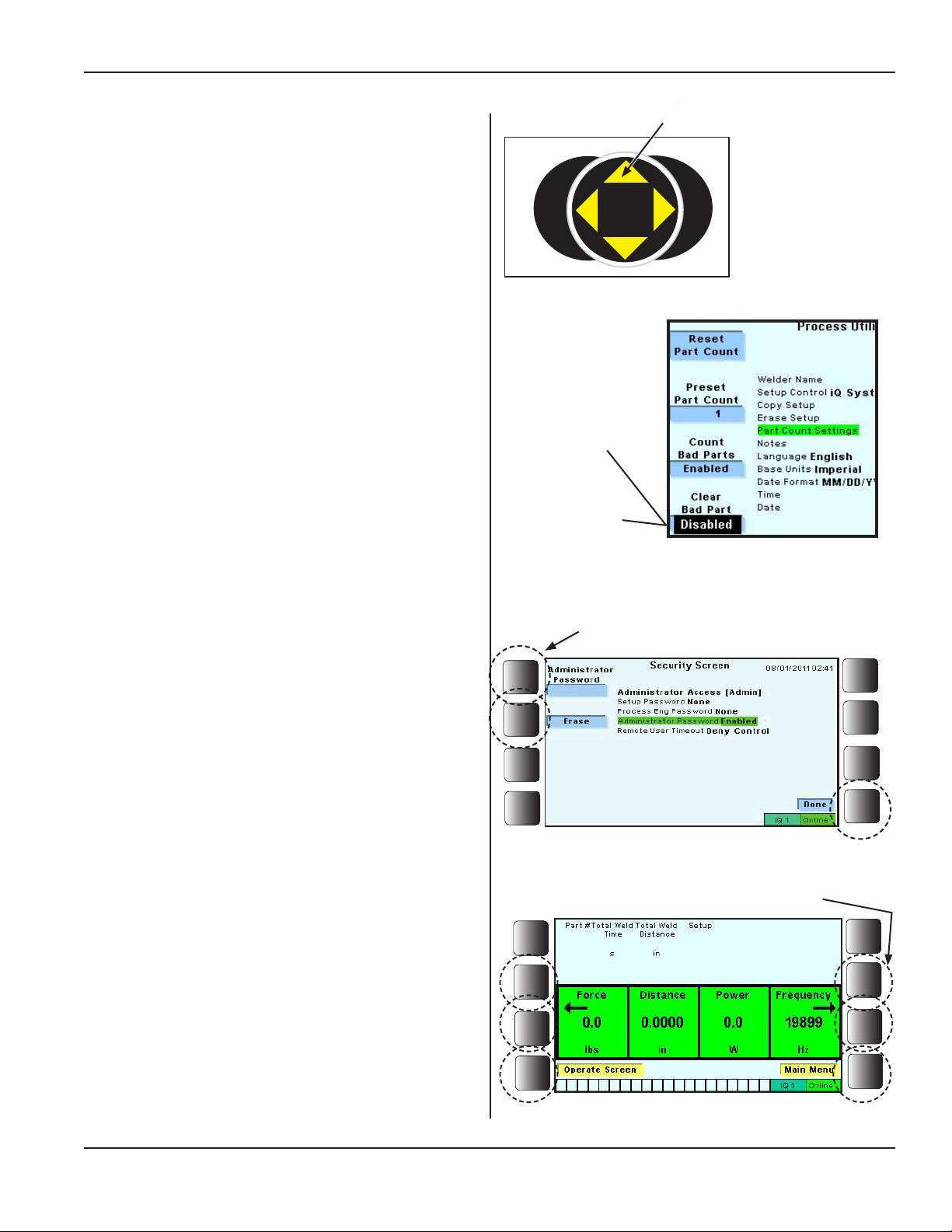
Section 4 - Control Panel
Navigation Keys
Moving the Cursor - Press the left and right navi-
gation keys to move the display’s cursor left or right
respectively.
Press the up and down navigation keys to move up one
level in the menu, or to move back one level. Also, use the
keys to change the value of a selected digit.
Enable/Disable - The navigation keys have another
function. Any of the four keys can be pressed to either
enable or disable a particular menu item.
See Figure 4-4.
ENTER Key
Press ENTER to conrm and store a selection in memory.
Example: After entering a time value, press ENTER.
CANCEL Key
Press the CANCEL key to return to the previous screen
or cursor position. Think of it as a “back” key. Selection
is not stored in memory.
Navigation Key (4)
L
E
C
N
A
C
R
E
T
N
E
Press one of the
navigation keys to
Enable the func-
tion.
Press again, to
Disable the function once more.
Figure 4-4 Navigation Keys (4), with Enter and Cancel
Active Key
Soft Keys Bordering the Display (8)
Use the eight keys that border the display to make selections from the choices shown on the display.
Not all keys will be active on any given screen.
Example 1: For the display shown on the right, three of
the eight soft keys are active:
Administrator Password, Erase, and Done.
Example 2: At times the soft keys act like navigation keys
to help move from screen to screen. In the example shown
to the right, the two keys nearest the arrow (on either side
of the display) will respond to an operator's touch. The
arrows indicate more information is available - either left
or right. In the example shown in the gure to the right,
pressing the active soft key(s) will display more real time
data. If the lower active keys are pressed, they will display
the Operate screen (left) or the Main Menu (right).
Figure 4-5 Active Soft Keys, Example 1
Active Key
Figure 4-6 Active Soft Keys, Example 2
Dukane Manual Part No. 403-587-00
Page 41
Page 48
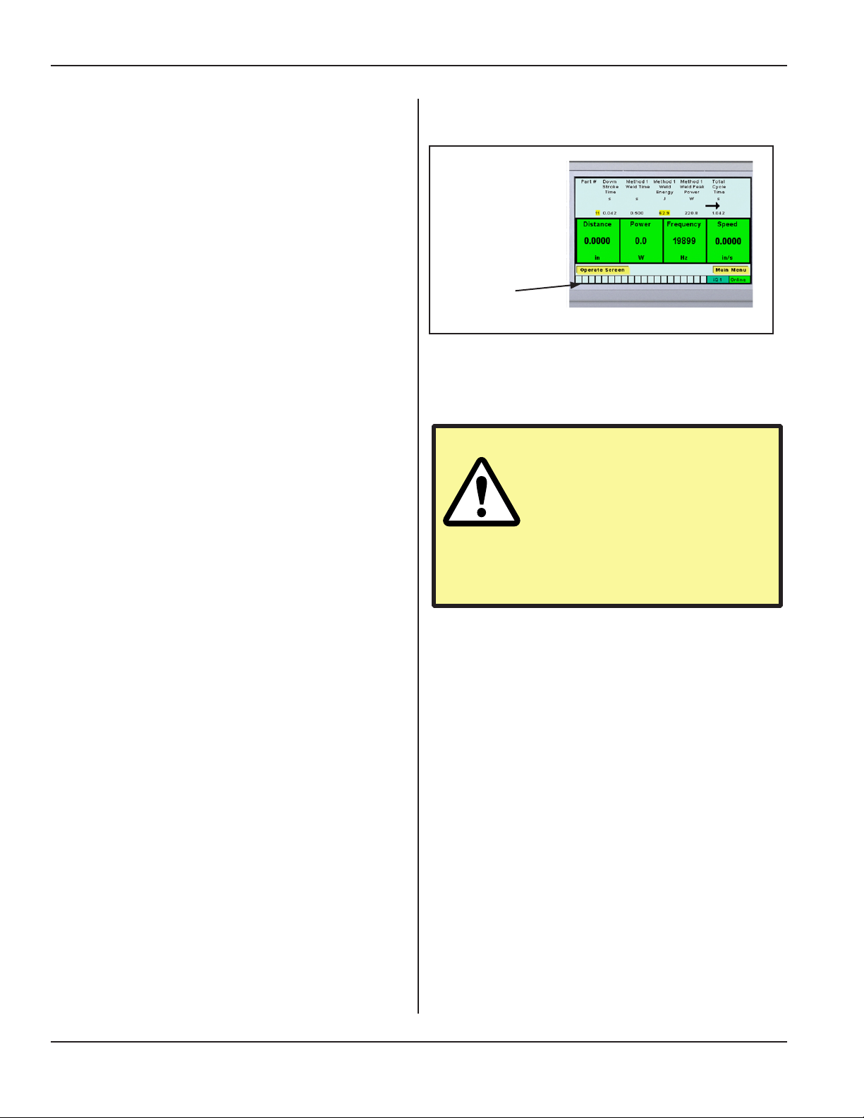
iQ Series Ultrasonic Generator/Power Supply, Servo Systems, ES User’s Manual
System Power Output Level
(Bar Graph)
A bar graph displays the percentage of ultrasonic power
being drawn by the load.
The display uses LED’s that show:
GREEN - normal operation.
YELLOW - warning of potential overload.
RED - warning that an overload condition exists.
Peak Detect Feature
To indicate the maximum peak power achieved during a
weld cycle, the LED in the bar graph corresponding to
the peak level remains on (for about one second) after the
weld cycle has been completed.
Flash on Overload at 90%
The OVERLOAD indicator begins to ash (RED) when
the generator produces 90% of the overload power rating.
This feature alerts the operator to an impending overload
fault condition.
Bar Graph Power Scaling
Power scaling is related to amplitude. At 100% amplitude
the whole graph is lit, and the generator is operating at
100% power. At 50% amplitude the entire graph is lit, and
the generator is operating at 50% power.
If the amplitude setting is lowered, the graph rescales
automatically according to the revised amplitude.
Example: With a 1200W generator, at 50% amplitude, if
the whole graph is lit, that represents 600W.
Bar Graph
Figure 4-7 System Power Output Level, Bar Graph and
Overload Indicator
CAUTION
If the System Output Power
Level red overload indicator
is lit, that means there is an
overload fault. If this hap-
pens, verify that the ultrasonic stack
is not damaged.
Lighted Power Indicator
While the indicator glows steady GREEN, it indicates that
the generator has been powered by the AC current.
Page 42
Dukane Manual Part No. 403-587-00
Page 49
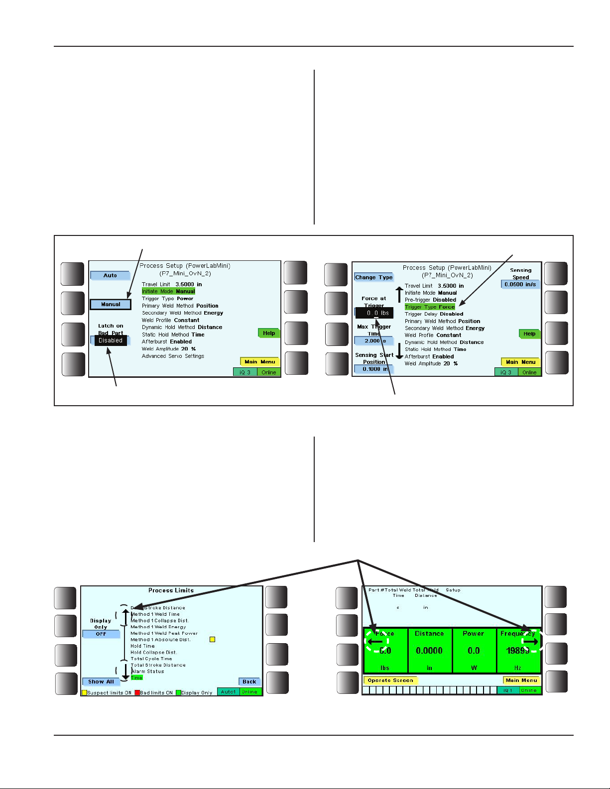
Screen Basics
Making Selections
Figure 4-8 shows there are several ways that an item has
been selected:
• A word or phrase is bounded by a black border.
• A black box surrounds the selected item.
• A line of text is highlighted.
• The cursor shows what digit is selected.
Section 4 - Control Panel
Word bounded by black border
Black box surrounds selected item
Figure 4-8 Making Selections
Interpreting On Screen Arrows
Arrows pointing up, down, left and right give visual cues
that more text is available in the direction the arrow points.
Two examples are shown in Figure 4-9 below. For the
screen on the left, the up or down navigation keys are used
to move the display. For the screen on the right, active soft
keys are used to move the display left or right.
Line of highlighted text
Cursor showing selected digit
(See Active Soft Keys, Figure 4-6.)
Figure 4-9 Arrows Indicate More Text
Dukane Manual Part No. 403-587-00
Display arrows point in the direction of more text.
Page 43
Page 50
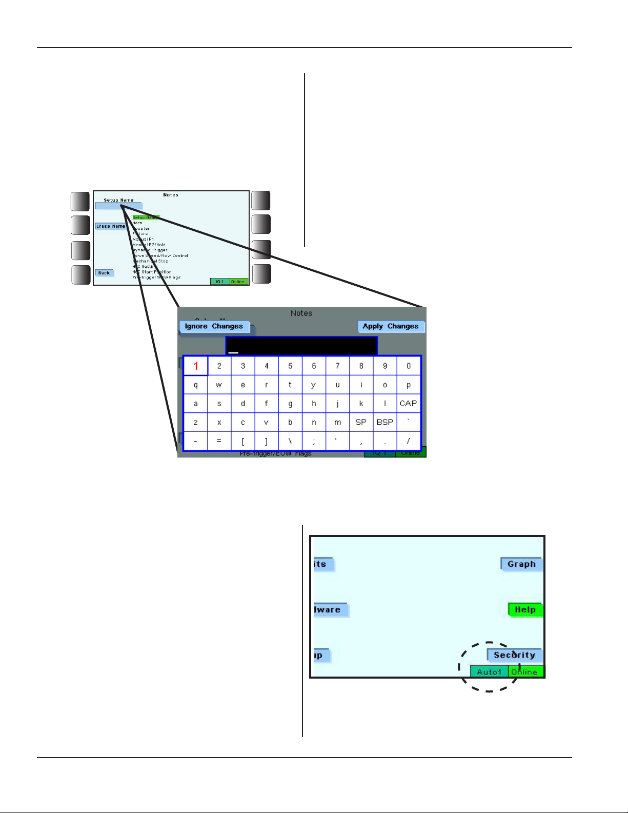
iQ Series Ultrasonic Generator/Power Supply, Servo Systems, ES User’s Manual
Virtual Keyboard
A virtual keyboard pops up when there is a need to make
an entry for the Security and Hardware screens.
In the example shown below the operator is prompted to
choose a Setup Name.
Figure 4-10 Virtual Keyboard
Setup Identication
Setupidenticationcanbeseeninthelowerrightcorner
ofthescreen.
TheexampleshowninFigure4-11illustratesthatsetup
controlisbyautomation(Auto)andthatSetup#1programhasbeenselectedforthegenerator.
Setup can also be controlled by iQSystem(iQ) or by se-
quencing(Apairofnumbersthatresemblearatiosuchas
2:3appears.Inthisexample2isthenumberforthesegment,and3isthenumberofthecycleinthatsegment.)
See Page 69 for more on Setup.
Page 44
Figure 4-11 Main Menu Detail - Setup Identication
Dukane Manual Part No. 403-587-00
Page 51

Section 5 - Operation
SECTION 5
Operation
Overview...................................47
Generator Start-up Sequence ..................47
Stopping the Weld Cycle ......................48
Using the Menus.............................49
Process Setup................................ 50
Process Limits................................ 62
Utilities/Hardware ............................. 68
Operate Screen............................... 84
Current Setup ................................ 84
Graph ...................................... 85
Help........................................ 87
Security ..................................... 88
Set-up Guidelines............................93
Dukane Manual Part No. 403-587-00
Page 45
Page 52

iQ Series Ultrasonic Generator/Power Supply, Servo Systems, ES User’s Manual
This page intentionally left blank
Page 46
Dukane Manual Part No. 403-587-00
Page 53
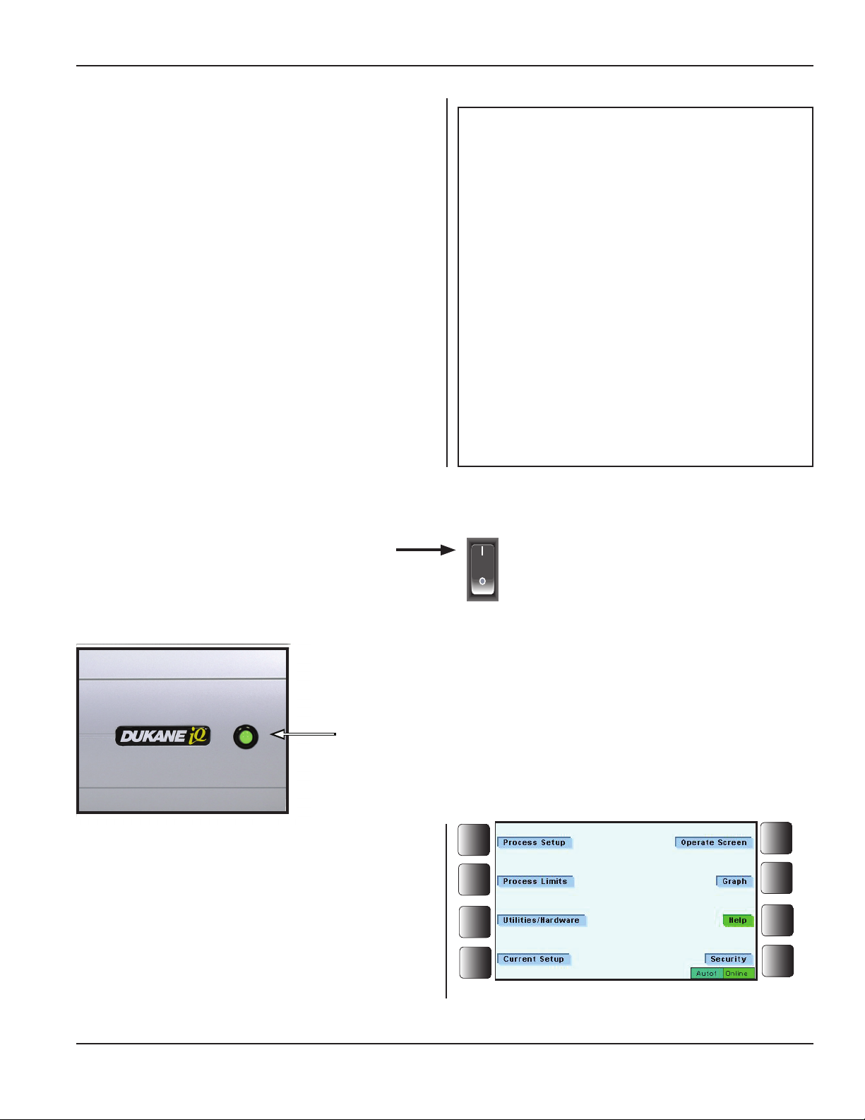
Section 5 - Operation
Overview
The iQ Series generator, model ES, is typically part of a
system. Major system major components would be:
• iQ generator,
• iQ Explorer II (software),
• User Interface (HMI),
or computer (user supplied), and
• iQ Press System.
Press, acoustic stack, and tooling will
require their own individual adjustments as
those components are integrated into your
particular system.
Helpful information on a wide variety of
assembly equipment, processes and
With this type of system, the user controls nearly all aspects
of the welding process and has several choices of how best
to accomplish this:
Control can be done through the color front panel of the
iQ ES generator.
System control can also be done with the User Interface
(HMI) or a computer (user supplied), using iQ Explorer II.
techniques can be found at the Dukane
website:
http://www.dukane.com/us/PPL_upa.htm
See Downloads for these User Manuals:
• iQ Explorer II (Part No. 403-585-00),
•iQ Press System ES (Part No. 403-569-00), and
•iQ Press System Servo ES (Part No. 403-578-00).
Generator Start-up Sequence
NOTE
1. Press the rear panel AC breaker switch to ON.
2. The front panel lighted power indicator ashes during
the start up sequence, then turns a steady GREEN (See
Figure 5-1) when the generator is activated.
Lighted Power
Indicator
Figure 5–1 Front Panel's Lighted Power Indicator
3. After the generator is activated, the LCD displays an
image that identies the Dukane iQ Series type. The
sequence ends when the Main Menu screen is displayed
as shown in Figure 5-2.
(ON)
(OFF)
Dukane Manual Part No. 403-587-00
Figure 5–2 Main Menu Screen
Page 47
Page 54

iQ Series Ultrasonic Generator/Power Supply, Servo Systems, ES User’s Manual
Stopping the Weld Cycle
Normal Conditions
The cycle stops when the programmed welding cycle ends
or when the rear panel's Cycle Stop input is activated.
NOTE
Emergency Conditions
Push the power switch on the generator's rear panel to the
OFF position. The front panel lighted power indicator goes
out showing that power has been turned off.
Manual System
Do either of these things:
1. Press OFFLINE to stop the ultrasound signal. This
may be done under any condition, OR
2. Push the power switch on the generator's rear panel to
the OFF position.
Automated System External Controls:
Customer-supplied external controls provide the means to stop the cycle for an
automated system.
An auxiliary cable connects these external
controls to the iQ generator at connector
J2.
Activating the System Input called "Automation Cycle Stop" will stop the weld process
or the complete cycle depending on if it's
congured for "End of Weld" or "End of
Cycle." See Page 20 for a description of
Automation Cycle Stop Input.
Page 48
Dukane Manual Part No. 403-587-00
Page 55
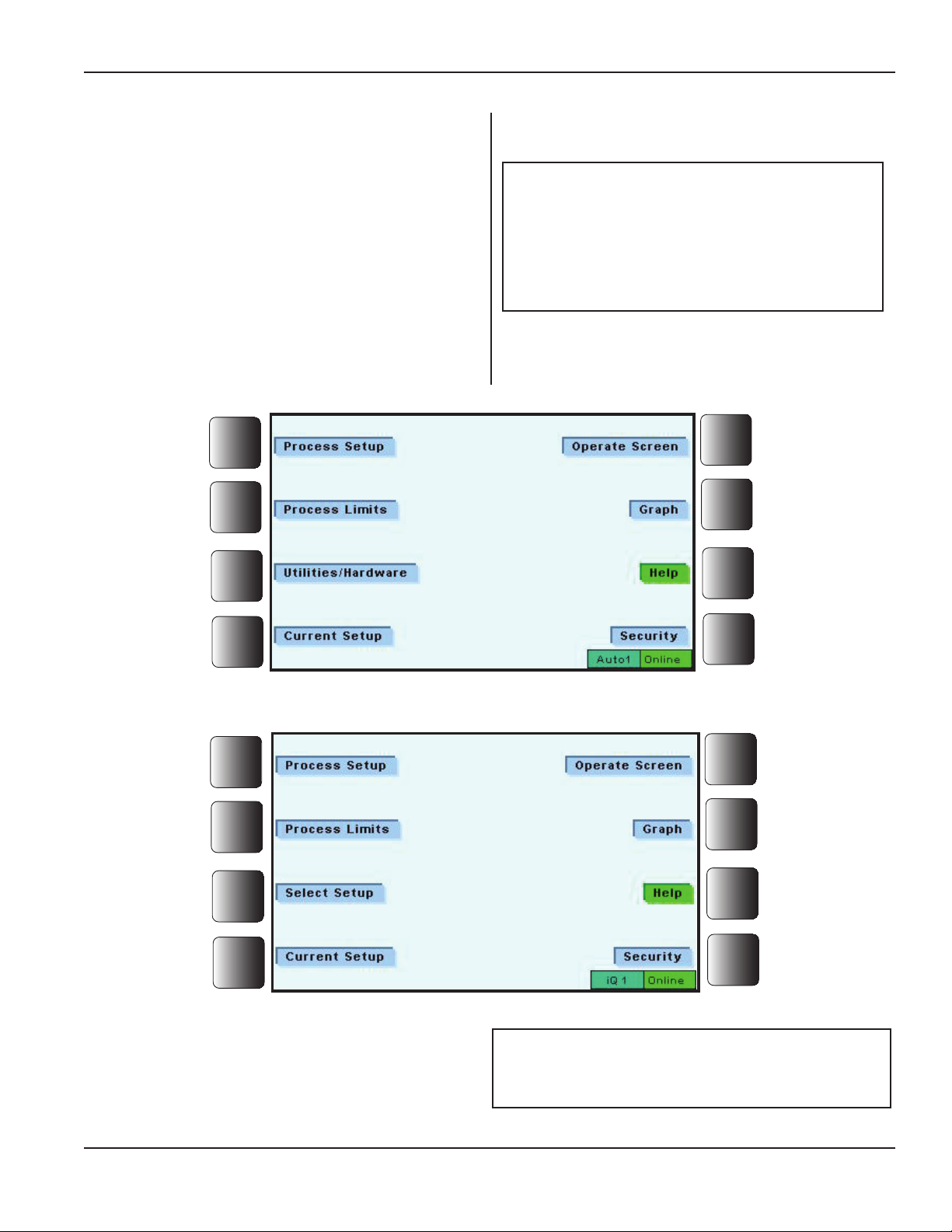
Using the Menus
Navigation through the menus typically begins at the Main
Menu. This menu can take two forms as shown below. If
either the Administrator or Process Eng (Process Engineer) has logged in, the screen looks like that shown in
Figure 5-3. If Setup has logged in, the screen looks like
that shown in Figure 5-4.
The screens look identical with one exception:
The Administrator/Process Engineer screen has Utilities/
Hardware while the Setup screen has Select Setup. Go to
the pages referenced for more detail about each sub-menu.
Section 5 - Operation
NOTE
Screen Prompts - Whenever a message pops up on the screen, please
follow its instructions or take note of a
condition, and take appropriate action.
Pages 50-61
Pages 62-67
Pages 68-83
Page 85
Figure 5–3 Navigating from the Main Menu (Administrator/Process Engineer Logged In)
Page 84
Pages 86-87
Page 87
Pages 88-92
Page 70
Figure 5–4 Navigating from the Main Menu (Setup Logged In)
Security detail can be found on Pages 88-92.
Dukane Manual Part No. 403-587-00
NOTE
Page 49
Page 56
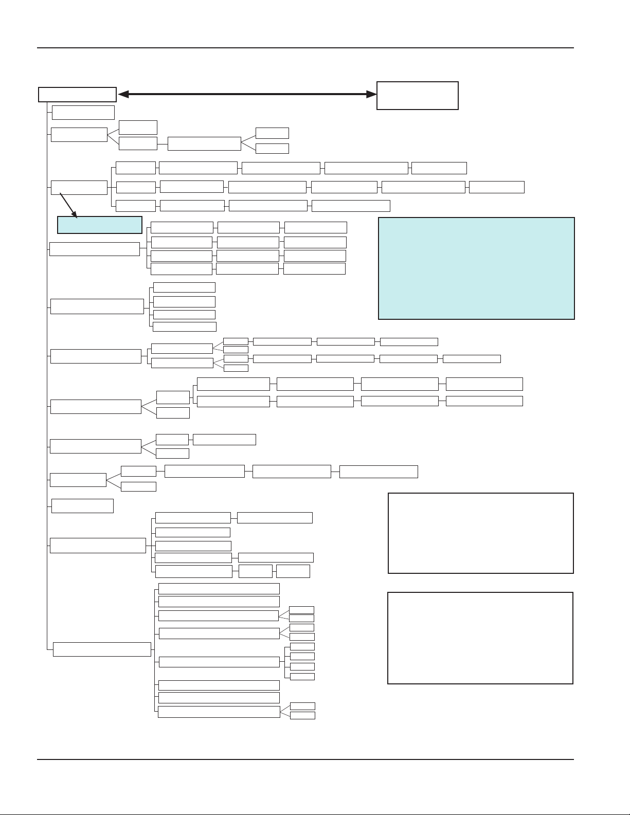
iQ Series Ultrasonic Generator/Power Supply, Servo Systems, ES User’s Manual
Process Setup
Travel Limit
Initiate Mode
Trigger Type
** See NOTE.
Primary Weld Method
Secondary Weld Method
Weld Prole
Dynamic Hold Method
Auto
Manual
Force
Power
Position
Latch on Bad Part
Force at Trigger Max Trigger Time
Trigger Power
Trigger Position
Distance
Position
Energy
Peak Power
Disabled
Position
Energy
Peak Power
Constant
Segmented
Enable
Disable
Weld Distance Max Weld Time
Weld Position
Weld Energy
Weld Power
Enable
Disable
Enable
Disable
Until Force Reached
Distance
Enable
Disable
Max Trigger Time
Teach Trigger Position
Constant Weld Speed Enable Melt Detect
Speed
Sensing Start Position
Start Amplitude
Max Trigger Time
Max Weld Time
Max Weld Time
Max Weld Time
Distance Increment
Dynamic Hold Speed
Hold Distance
Main Menu
Sensing Speed
Sensing Start Position
**
Trigger by Force and Trigger by
Position have Pre-trigger and
Trigger Delay Trigger features
not shown here but described on
Page 82.
After Force Drops By
Enable Melt Detect
Dynamic Hold Speed
Sensing Speed
NOTE
After Force Drops By
Max Hold TimeDynamic Hold Peak Force
Max Hold Time
Static Hold Method
Afterburst
Time
Disable
Enable
Disable
Hold Time
Afterburst Delay Time
Weld Amplitude
Top of Stroke Position
Acceleration
Advanced Servo Settings
Deceleration
Travel Limit
Weld Motion Control
Free Run Frequency
Scan Stack
Frequency Tracking
Frequency Lock and Hold
Advanced Process Settings
System Frequency Limits
Ramp Up Time
Ramp Down Time
Restore Advanced Process Defaults
Figure 5–5 Process Setup Menu Diagram
Afterburst Duration Afterburst Amplitude
Teach Top of Stroke
Teach Travel Limit
Speed
Force
Enable
Disable
Wide
Normal
Narrow
Manual
Yes
Enable
Disable
No
NOTE
Options for Secondary Weld
Method choices are dependent
on the Primary Weld Method
choices that have been made.
NOTE
Available weld choices depend
on Security access level (See
Table 4-II.) system conguration, and primary weld method.
Continued
Page 50
Dukane Manual Part No. 403-587-00
Page 57
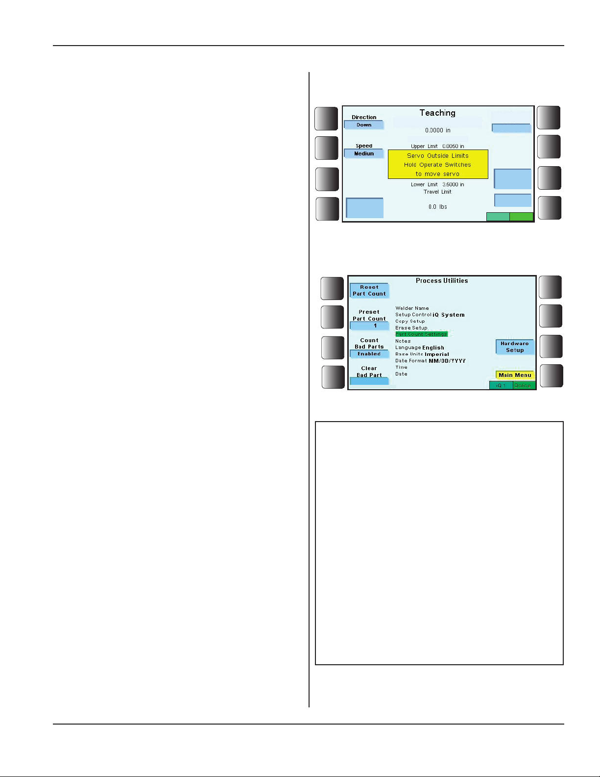
Continued from Previous Page
Process Setup
The rst submenu of Process Setup to consider is:
Section 5 - Operation
Travel Limit
This setting sets the position limit the servo press
is permitted to travel. Its purpose is to prevent
contact between the horn and xture. This position is
monitored continuously throughout the weld.
See additional information on Page 55.
Initiate Mode
Initiate Mode controls the way a cycle is started, using
either of two modes, Manual or Auto.
Manual
The cycle is started by depressing both operate switches
on the press base (Operate Switch 1 and Operate Switch
2) within 0.35 seconds of each other.
Depress the operate switches continuously until the
trigger switch on the press has activated or until the
ultrasonic signal is applied.
Latch on Bad Part
When this feature is active (It is available only with the
Manual Initiate mode.), the cycle stops when a bad part
is detected, and SYSTEM LOCKED, Bad Part Limit
Exceeded, LATCHED appears on the iQ display. The
operator must deal with the LATCHED message before
a new cycle will start.
The next cycle will not activate until the latch is cleared.
There are two ways the latch can be cleared:
•RemovetheLATCHED Message from the Display
1. Go to the Main Menu.
2. Go to Utilities, and then to Part Count Settings.
3. Enable Clear Bad Part. (See Figure 5-7 to the
right.)
When these three steps are completed, the operator can
press the ENTER key to clear the latch, or
•ActivatetheSystemLatchResetInput
The System Latch Reset Input signal (Pin 12 of J2, the
System Inputs connector) can be activated.
Travel Limit
Weld Position
Select
Parameter
Figure 5-6 Teaching Travel Limit
Enabled
Figure 5-7 Enable Clear Bad Part
Travel Limit
Move to
Saved Pos
Back
iQ 5
NOTE
What is a “bad part”? Bad part limits dene what is considered to be a bad part.
If the UPPER limit of a selected characteristic is reached during its phase of the
weld cycle, the weld process is stopped,
and the part is identied as a bad part.
If the LOWER limit of a selected parameter
is not reached by the end of its phase of
the weld cycle, the assembly process is
stopped, and the part is identied as a
bad part.
See Pages 66-67.
Online
See Page 20 for information about Pin 12 of the System
Inputs (J2) connector. The pin can be used for latch reset.
Dukane Manual Part No. 403-587-00
Process Setup, Continued
Page 51
Page 58
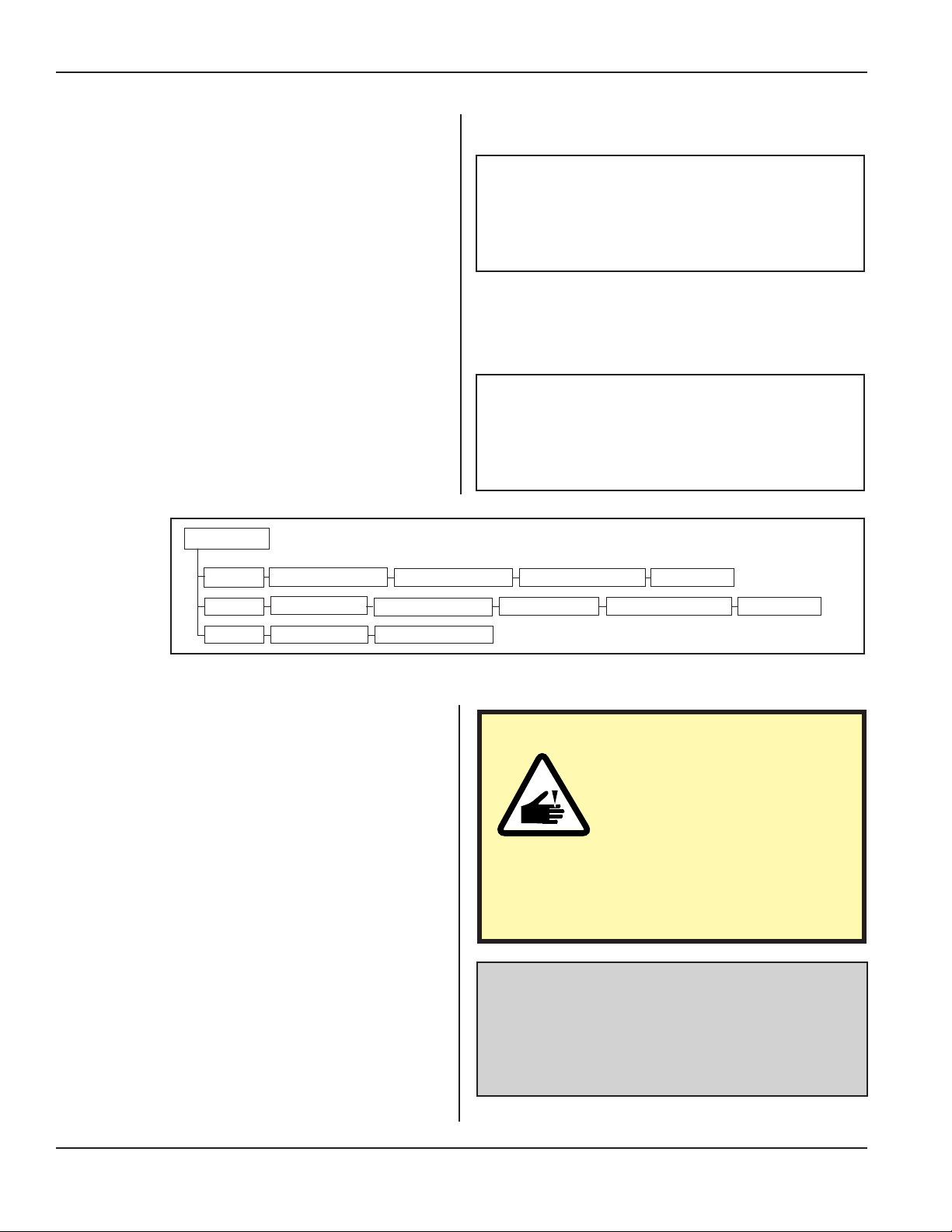
iQ Series Ultrasonic Generator/Power Supply, Servo Systems, ES User’s Manual
Process Setup, Continued from Previous Page
Auto (Initiate Mode)
The AUTO mode requires a voltage signal applied to
J2 pin 8. The applied voltage level, either ground or
+22VDC, must be the opposite of the voltage level
applied to J2 pin 13. See Pages 19 and 20 for additional
information.
Apply the auto input signal for a minimum of 50 millisec-
Pre-trigger and Trigger Delay information
can be found on Page 82.
onds to ensure that the cycle has been started.
Trigger Type
Trigger Type is the next Process Setup submenu.
NOTE
“Trigger” denes the type of event that turns on the ultrasound signal. This event can be:
• a force level from the force load cell,
• a power level reached by the generator, or
• a position reached by the thruster.
Typescanbe:
Trigger Type
•Force
•Power
•Position
Force
Power
Position
Figure 5-8 Trigger Type Submenu Diagram
Force at Trigger Max Trigger Time
Trigger Power
Trigger Position
Max Trigger Time
Max Trigger Time
NOTE
Available trigger types depend on system
conguration, and primary weld method.
Sensing Start Position
Start Amplitude
Sensing Speed
Sensing Start Position
Sensing Speed
CAUTION
Use extreme caution when
using the Momentary trigger
type. Opening the trigger
switch will NOT terminate the
weld cycle. Guard the horn/xture “pinch
point” to prevent hands, or ngers from being crushed by the vibrating horn.
Page 52
Program Notes
Afterselectingtheappropriatetriggertype,theoperatorentersdatawherethetriggertypecallsforit.
Forinstance,alltriggertypescallforaMax Trigger
Timetobeentered.
SeeFigure5-8,TriggerTypeSubmenuDiagram.
Process Setup, Continued
Dukane Manual Part No. 403-587-00
Page 59
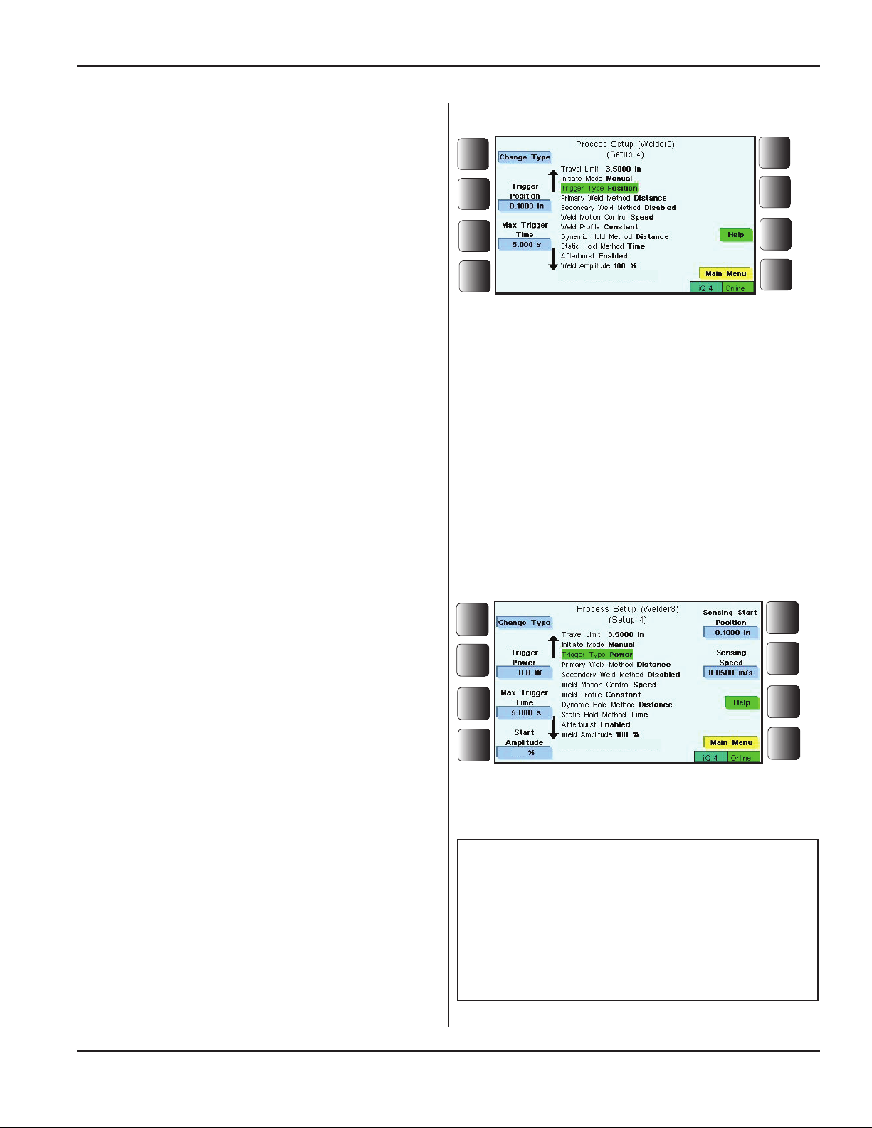
Process Setup, Continued from Previous Page
Position
The factory default setting for Trigger Type is Position.
After the system has completed the initiate mode, the press
head travels down at the Sense Speed until it has reached
the trigger position.
After the trigger position is reached, it then changes to
the programmed welding speed.
Section 5 - Operation
The gure to the right shows the Process Setting menu
appearance when Position is the trigger type.
Set the trigger position. This is the place on the distance
encoder where the ultrasound signal will be activated.
A secondary parameter Max Trigger Time needs to be pro-
grammed as well. If the weld is not accomplished within
the set time, the weld will be terminated.
Power
Dukane has patented its Trigger by Power feature. Go
to Dukane's blog: http://usblog.dukane.com/2010/01/
trigger-by-power-feature-aids-weld_27.html for more
information about this feature.
During the downstroke, the ultrasound signal is immediately turned on with the Start Amplitude setting. When the
power level reaches the trigger value, the weld amplitude is
applied. Choose this trigger type when the operator wants
the ultrasound signal to start as the horn touches the part
to be welded. If the maximum trigger time is reached, the
weld is aborted and the press is returned to top of stroke.
Figure 5-9 Trigger Type - Position
TheguretotherightshowsthatwithPower as the
triggertype,veotherparametersneedtobeset:
Trigger Power, Max Trigger Time, Start Amplitude,
Sensing Start Position, and Sensing Speed.
Dukane Manual Part No. 403-587-00
100
Figure 5-10 Trigger Type - Power
NOTE
MAX TRIGGER TIME is a secondary characteristic of Position, Power and Force. The
time forces the weld portion of the cycle to
stop even if the specied control parameter
is not met.
Process Setup, Continued
Page 53
Page 60
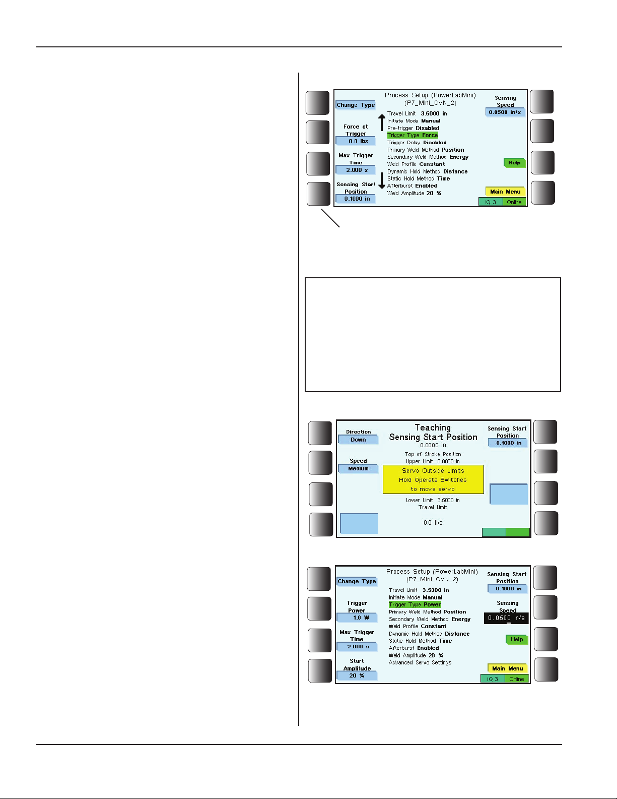
iQ Series Ultrasonic Generator/Power Supply, Servo Systems, ES User’s Manual
Process Setup, Continued from Previous Page
Force
TheguretotherightshowsthatwithForce as the trig-
ger type, Trigger Force, Max Trigger Time, Sensing
Start Position, and Sensing Speed need to be programmed.
Sensing Start Position
A feature of the servo press teaches a Sensing Start Position. This position can be programmed once the Sensing
Start Position (Figure 5-11) soft key is pressed. That
will be a choice when either force or power is the trigger
type.
The gure to the right illustrates the display that appears
Sensing Start Position Soft Key
after the soft key is pressed. In this case, because the
Figure 5-11 Trigger Type - Force
servo is outside its limits, the operator is prompted to
hold the operate switches so that the servo thruster can
move. Once it is moved, the Sensing Start Position can
be set.
It is critical to program the Sensing Start Posi-
Sensing Start Position is the actual position in the machine travel where the system begins to sense for the
trigger force to be achieved. As the horn approaches the
Sensing Start Position, the servo changes to the Sensing
Speed setting.
tion so that the horn is never in contact with
the part at this position, taking into account the
height variability of unwelded parts. Failure to
do so may result in equipment damage.
NOTE
Sensing Speed
Press the Sensing Speed softkey.Figure5-13shows
thatthespeedwillbesetinthehighlightedarea.Usethe
navigationkeystoselectdigits.Whennished,press
ENTER.
SensingSpeedisthespeed(inchesormillimetersper
second) at which the horn travels between the Start Sens-
ing Position and just before achieving the trigger point.
A typical starting value of Sensing Speed is 0.040 in/s
(1.0 mm/s). Sensing Speed can be set higher for shorter
cycle times, or lower for greater trigger force detection
accuracy.
Move to
Saved Pos
Select
Parameter
Figure 5-12 Teaching Sensing Start Position
iQ 5
Online
Page 54
Figure 5-13 Setting Sensing Speed
Process Setup, Continued
Dukane Manual Part No. 403-587-00
Page 61

Process Setup, Continued from Previous Page
Teach a Position
There are various programmable positions in a servo
press setup. Access to this process is made available
through screens such as shown in Figure 5-11 on the
previous page.
Moving the Thruster - Tomovetheservopress/
thrusterduringtheteachingprocesstheuserwillusethe
opticalswitcheslocatedonthebase.Whenthegenerator
isplacedintoateachingmode,theswitcheswillnot
triggeraweld.
Speed - There are three speeds available in the teach
window.Thelowspeedisextremelyslowandismeant
fornetuningtheposition.Thehighspeedsettingis
quitefastandmeanttogettheservopressfromtopof
stroketothepartquickly.However,youwillndthatthe
mediumspeedsatisesmostneeds.
Direction - The direction to jog the servo press up or
downcanbechangedaswell.
Section 5 - Operation
Duringtheteachingprocess,theuserwillgetfeedbackon
forceandcurrentpositionfromtheon-screendisplay.
Move to Saved Position - If a previous position has
been set, the user can press the Move to Saved Position
buttonandusetheswitchestomovetheservoatthehigh
speedtothepreviousposition.Fineradjustmentscanbe
madefromthereifdesired.
Select Parameter-Chooseaparameterfromthelist
ofthreechoices:
•TopofStrokePosition,
•SensingStartPosition,or
•TravelLimit.
Dukane Manual Part No. 403-587-00
Process Setup, Continued
Page 55
Page 62

iQ Series Ultrasonic Generator/Power Supply, Servo Systems, ES User’s Manual
Process Setup, Continued from Previous Page
Primary Weld Method
Primary Weld Method is the next Process Setup submenu.
Theweldmethoddeneswhentheultrasoundsignalis
terminatedafterithasbeentriggered.
Select from four choices:
Distance - The system welds until the press travels
the user-specied distance from the trigger point.
A user-specied maximum time prevents innite
welding due to an unreachable distance.
Primary Weld Method
Distance
Position
Energy
Peak Power
Figure 5-14 Primary Weld Method Submenu Diagram
Weld Distance Max Weld Time
Weld Position
Weld Energy
Weld Power
Max Weld Time
Max Weld Time
Max Weld Time
Position - The system welds until the press
travels to the position measured from the reference
mark (zero position) of the distance encoder. A user
specied maximum time prevents innite welding due
to an unreachable position.
Energy - The system welds until the generator
delivers a specied level of energy to the transducer
while the horn is in contact with the part. A user-
specied maximum time prevents innite welding due
to an unreachable energy level.
Energy, measured in joules, has a range of 0 to
100000.0, and has a 0.1 joule resolution.
Peak Power - The system welds until the generator
delivers a specied level of power to the transducer.
A user-specied maximum time prevents innite
welding due to an unreachable power level.
Peak Power, measured in Watts, has a 0.1 Watt
resolution.
Peak Power range is dependent on the generator's maximum output power rating.
Secondary Weld Method
Secondary Weld Method is the next item to consider
in the Process Setup menu.
The secondary weld method denes an alternative
control to terminate the ultrasound signal after it has
been triggered.
The feature may be disabled or there are three weld
methods from which to choose: Position, Energy, and
Peak Power.
NOTE
Downstroke Distance = Distance the horn
travels until the ultrasound trigger point is
reached.
Weld Distance = Distance the horn moves
during the application of ultrasound to create the weld.
Hold Distance = Distance the horn moves
during the hold or “cooling” portion of the
weld cycle.
End Position = Downstroke Distance +
Weld Distance.
NOTE
Options for Secondary Weld Method choices
are dependent on the Primary Weld Method
choices that have been made.
Disabled
Secondary Weld Method
Figure 5-15 Secondary Weld Method Submenu
Diagram
Position
Energy
Peak Power
Page 56
Process Setup, Continued
Dukane Manual Part No. 403-587-00
Page 63
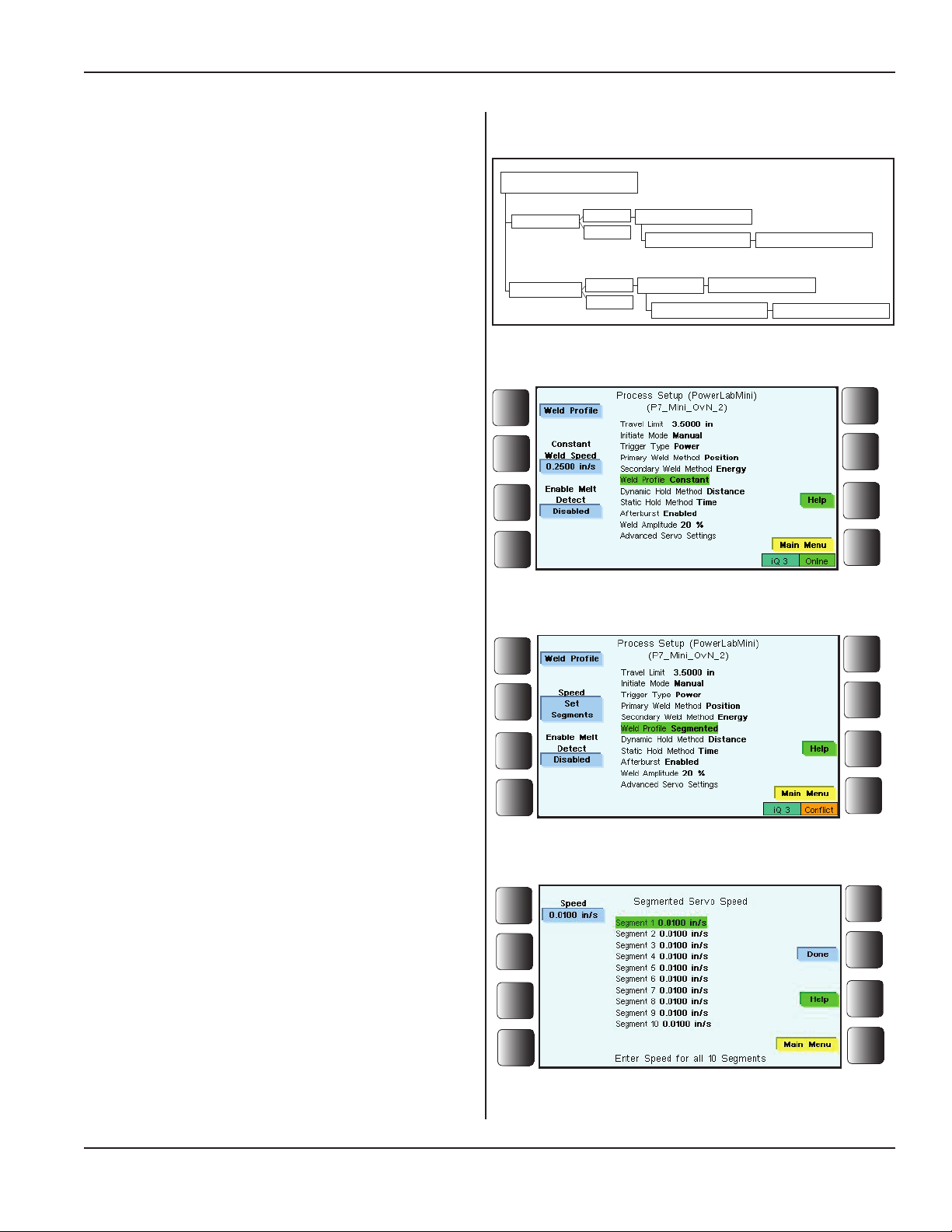
Process Setup, Continued from Previous Page
Weld Prole
Weld Prole is the next Process Setup submenu.
Section 5 - Operation
This setting determines whether a constant force or
speed is applied during the weld process or whether a
10-segment prole of forces or speeds is applied.
Constant Speed or Force - The constant speed
or force specied by the user is applied to the servo
for the duration of the weld.
Figure 5-17 to the right shows that Constant Weld
Speed needs to be set when choosing Constant.
Segmented Speed or Force - The speed
or force prole entails a set of 10 parameters that
determine what speed or force is applied during the
specied segment of the weld process.
See Figure 5-18 and Figure 5-19 to the right.
Distance Increment - When the weld method
is energy or peak power, a user-specied distance
increment is required to determine the length of each
of the prole segments to track when to transition
from one prole segment to the next.
Weld Prole
Constant
Segmented
Figure 5–16 Weld Prole Submenu Diagram
Figure 5–17 Weld Prole Constant
Enable
Disable
Enable
Disable
Constant Weld Speed
Enable Melt Detect
Speed
Enable Melt Detect
Distance Increment
After Force Drops By
After Force Drops By
Enable Melt Detect - Enabling Melt Detect
allows for greater control of the part's collapse speed
prole. When enabled, another parameter must be
addressed: After Force Drops By.
After Force Drops By - The melt detect portion
of the weld is linked to the force applied by the
press, but only after the initial force drops by a given
percentage. It is this percentage that is entered for this
parameter (in the range of 0% to 50%).
Figure 5–18 Weld Prole Segmented
Figure 5–19 Setting Speeds for the Segments
Process Setup, Continued
Dukane Manual Part No. 403-587-00
Page 57
Page 64
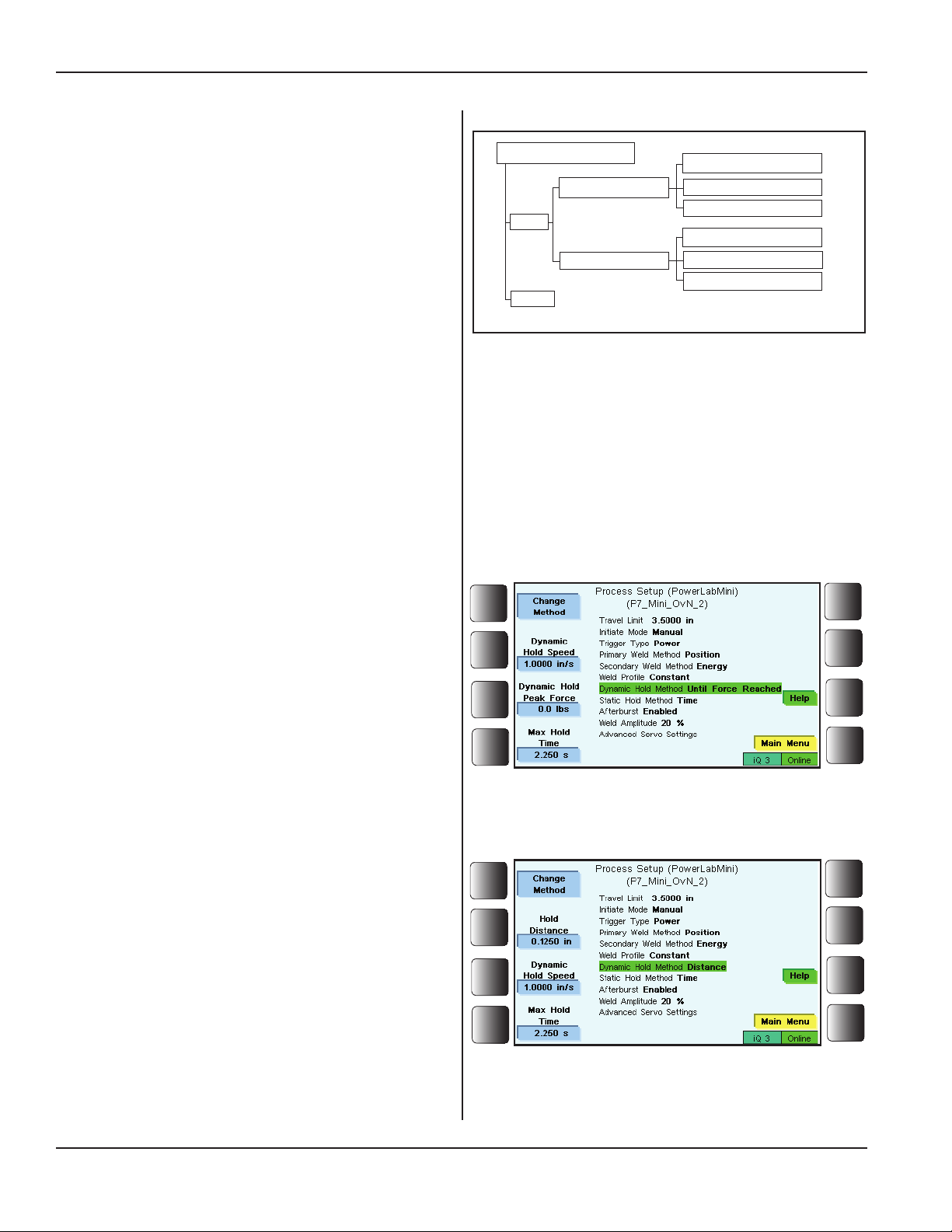
iQ Series Ultrasonic Generator/Power Supply, Servo Systems, ES User’s Manual
Process Setup, Continued from Previous Page
Dynamic Hold Method
The hold process related to the servo press is split into two
parts. The dynamic hold is executed before the static hold.
The hold process can include one or both of these methods
and both may be disabled.
The dynamic hold method occurs after the weld method
has completed. The dynamic hold method continues the
movement of the horn until a user-specied distance occurs
or until a user-specied force is achieved. Holding allows
the material to solidify (under pressure) before the press
head retracts. Hold method choices are:
• Until Force Reached,
• Distance,
• Disabled
Until Force Reached - This setting keeps a user-dened
speed on the part until the force of the press reaches the
specied peak force following the weld process. A user
specied maximum time prevents an innite hold. This
option is only available when using speed motion control.
A user specied maximum time prevents innite holding
due to an unreachable distance.
Dynamic Hold Method
Until Force Reached
Enable
Distance
Disable
Figure 5–20 Dynamic Hold Method Submenu Diagram
Dynamic Hold Speed
Dynamic Hold Peak Force
Max Hold Time
Hold Distance
Dynamic Hold Speed
Max Hold Time
Distance - This setting determines the distance the press
travels following the weld process. Depending on the mo-
tion control mode, the user dened force or speed will be
applied to the part. A user specied maximum time prevents
innite holding due to an unreachable distance.
Hold Distance - The distance the press head travels
following the weld process.
Dynamic Hold Speed - The speed at which the press
head travels until the user specied distance is met.
Max Hold Time - The maximum amount of time the
press will apply pressure to the part during the hold
process.
Disabled - This setting disables dynamic hold and its options.
Figure 5–21 Dynamic Hold Method - Until Force
is Reached
Figure 5–22 Dynamic Hold Method - Distance
Page 58
Process Setup, Continued
Dukane Manual Part No. 403-587-00
Page 65
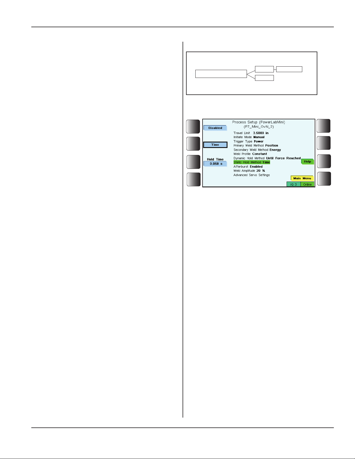
Process Setup, Continued from Previous Page
Static Hold Method
The hold process related to the servo press is split into two
parts. The static hold is accomplished after the dynamic
hold. The hold process can include one or both of these
methods and both may be disabled.
Static Hold Method
Time
Disable
Section 5 - Operation
Hold Time
Static Hold determines the amount of time the press position
is held following the dynamic hold process (if enabled) or
the weld process (if dynamic hold is disabled).
Disabled
Choose Disabled when no static hold method is needed.
Time
Thissettingdeterminestheamountoftimethepress
positionisheldfollowingthedynamicholdprocess
(ifenabled)ortheweldprocess(ifdynamicholdis
disabled).SeetheFigure5-24totherightshowing
the Static Hold Methoddisplay.
Figure 5–23 Static Hold Method Submenu Diagram
Figure 5–24 Static Hold Method Display
Dukane Manual Part No. 403-587-00
Process Setup, Continued
Page 59
Page 66
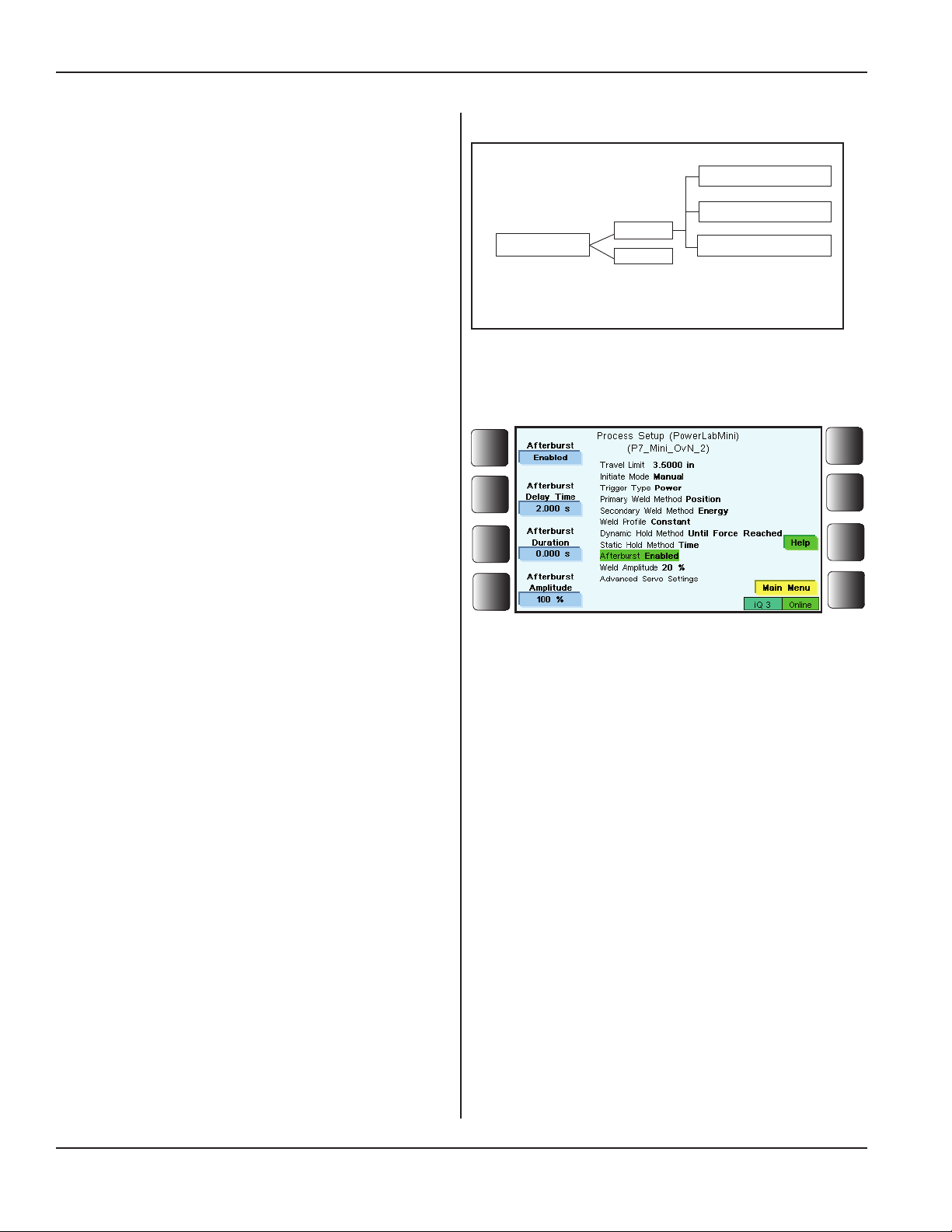
iQ Series Ultrasonic Generator/Power Supply, Servo Systems, ES User’s Manual
Process Setup, Continued from Previous Page
Afterburst
The next submenu in Process Setup deals with Afterburst.
In some applications the part being welded may stick to
the horn as the head of the press retracts. Afterburst dislodges the part by sending a short burst of ultrasound on
the upstroke.
Afterburst is dened by three values: the delay time, the
duration of the afterburst, and by the amplitude.
Afterburst
Enabled
Disabled
Afterburst Delay Time
Afterburst Duration
Afterburst Amplitude
Delay is the time from the start of the upstroke until the
start of the afterburst.
Duration is how long the afterburst ultrasound signal is on.
Amplitude denes the amplitude of the afterburst ultra-
sound signal.
The afterburst feature can be turned off by choosing Dis-
abled, or it can be turned on by choosing Enabled.
When enabled, the delay and duration times and the ampli-
tude are then entered. See the gure to the right.
Weld Amplitude
Weld Amplitude is the next parameter to select. This refers
to the peak-to-peak excursion of the horn at its workface.
Amplitude settings are given as a percent of the horn’s
nominal amplitude in the range of 20% - 100%.
Figure 5–25 Afterburst Submenu Diagram
Figure 5–26 Afterburst Display
Page 60
Process Setup, Continued
Dukane Manual Part No. 403-587-00
Page 67
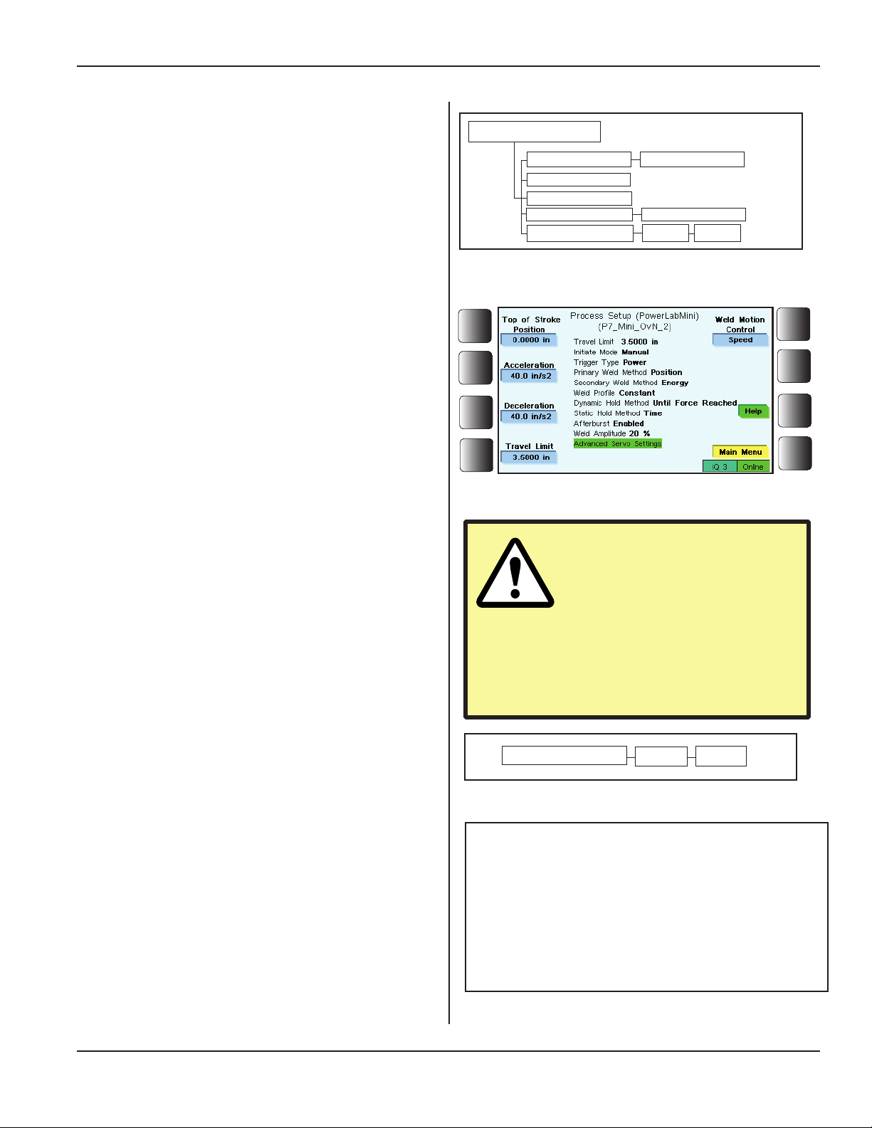
Process Setup, Continued from Previous Page
Advanced Servo Settings
The servo press makes available some advanced settings
and operations. See Figure 5-27 for the Advanced Servo
Settings submenu diagram.
Figure 5-28 shows the color front panel screen on which
values are entered for the four variables:
Top of Stroke Position - The thruster returns to
this position after each weld cycle.
Acceleration - The acceleration used to achieve the
velocity required of the servomotor when the speed is in
transition to a higher velocity.
Deceleration - The deceleration used to achieve
the velocity required of the servomotor when the
speed is in transition to a lower velocity.
Section 5 - Operation
Advanced Servo Settings
Top of Stroke Position
Acceleration
Deceleration
Travel Limit
Weld Motion Control
Figure 5–27 Advanced Servo Settings Submenu
Diagram
Teach Top of Stroke
Teach Travel Limit
Speed
Force
Travel Limit - This setting sets the position limit
the servo press is permitted to travel. Its purpose is
to prevent contact between the horn and xture. This
position is monitored continuously throughout the weld.
The maximum Travel Limit is based on the maximum
stroke distance of the press.
Weld Motion Control - This is the last of the Advanced
Servo Settings.
This setting determines whether force or speed is
controlled by the servo during the weld process.
Figure 5-29 at the right illustrates these choices.
Advanced Process Settings
Advanced Process Settings are enabled through the
Utilities/Hardware menu.
Please see Pages 78-83 for information on enabling these
settings and for brief descriptions of each setting.
Figure 5–28 Advanced Servo Settings Display
CAUTION
DO NOT make any adjustments to Acceleration or
Deceleration unless you
have first contacted qualified
Dukane personnel for guidance
in making any necessary adjust-
ments.
Weld Motion Control
Figure 5–29 Weld Motion Control Submenu Diagram
Speed
NOTE
Speed mode is highly recommended as it is
the only mode for which all press hardware
can be calibrated and validated. The Force
mode is provided only for the purposes of
experimentation and is not intended for
production.
Force
Dukane Manual Part No. 403-587-00
Process Setup, Continued
Page 61
Page 68

iQ Series Ultrasonic Generator/Power Supply, Servo Systems, ES User’s Manual
Process Limits
Overview
As the weld cycle progresses, time, distance, power, and
energy data are kept for each portion of the cycle. These
measurements, also called process characteristics, form
a process record for each part. Records’ analysis can establish parts limits which then can be used to determine if
the current process is “in control”. The iQ generator can
report the process characteristics as Bad or Suspect. The
characteristics can also be displayed or printed without
evaluation.
Limits are set using either statistical methods or physical
system constraints. Statistical methods can be applied
to pre-production parts that were evaluated for physical
characteristics of quality (e.g., strength, appearance).
Results of this evaluation are correlated to the process
characteristics. Limits for the characteristics related to part
quality are calculated. Other limits are determined by the
system itself. For instance, Total Cycle Time limits may be
established to end the cycle before an index table moves.
Downstroke Distance may be set to detect a misload or
incomplete assembly.
Available Process Characteristics
The list of available process characteristics is shown in
Figure 5 - 30 on the following page. This is followed by
brief descriptions of each characteristic.
NOTE
Of the available process characteristics,
the ones that apply to a particular part depend on the current iQ setup for that part.
Page 62
Process Limits, Continued
Dukane Manual Part No. 403-587-00
Page 69
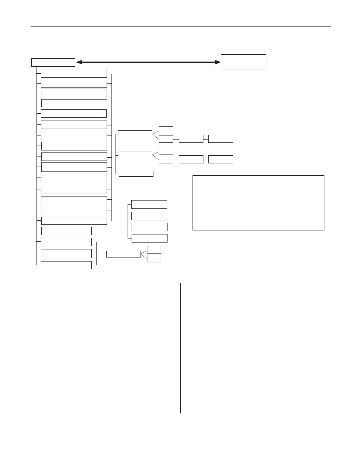
Process Limits, Continued from Previous Page
Section 5 - Operation
Process Limits
Downstroke Time
Position at Trigger
Trigger Delay Time **
Trigger Delay Distance **
Force at Trigger
Weld Time
Weld Distance
Weld Energy
Weld Peak Power
Weld End Position
Weld Peak Force
Hold Time
Hold Distance
Total Cycle Time
Total Stroke Distance
Alarm Status
Time
Date
Setup
** Limits available when Trigger Delay is enabled.
Suspect Limits
Bad Limits
Display Only
OFF
ON
OFF
ON
Low Limits
Low Limits High Limits
High Limits
The list of available process character-
Disabled
istics depends on Security access level
(See Table 4-II.) system conguration,
Display
Force Bad
Force Suspect
Display
OFF
ON
and on the chosen weld mode.
Main Menu
NOTE
Figure 5–30 Process Limits Menu Diagram
Dukane Manual Part No. 403-587-00
Process Limits, Continued
Page 63
Page 70

iQ Series Ultrasonic Generator/Power Supply, Servo Systems, ES User’s Manual
Process Limits, Continued from Previous Page
Process Characteristics Dened
Downstroke Time – This is the time from the start of the
welding cycle to the trigger point.
Position at Trigger – This is the position relative to the
home position of the mounted distance encoder at the
trigger point of a weld.
Force at Trigger – This is the force applied to the part
sampled at the instant of the trigger point.
Weld Time – This is the length of time the ultrasound is
applied to the part.
Weld Distance – This is the distance the press travels
while the ultrasound signal is applied to the part.
Weld Energy – This is the amount of energy drawn from
the generator while the ultrasound signal is applied to
the part.
Weld Peak Power – This is the highest instantaneous
power delivered to the transducer.
Weld End Position – This is the position relative to the
home position of the mounted distance encoder at the
instant of the end of the weld.
Weld Peak Force – This is the highest instantaneous force
that is measured during the weld method.
Hold Time – Thisisthetimethehornmaintains
pressure on the part after the ultrasound signal has
stopped.
Hold Distance - This is the distance the press travels
while maintaining pressure during the hold process,
after the ultrasound signal has stopped.
Total Cycle Time – This is the period from the start of
the weld cycle to the end of the weld cycle. The start
of the cycle is dened as the point the auto input signal
begins or when manual operate switches are activated.
The end of the cycle is dened as the point the head
retracts from the part.
Total Stroke Distance – This is the position relative to
the home position of the mounted distance encoder at
the end of the hold process.
Page 64
Process Limits, Continued
Dukane Manual Part No. 403-587-00
Page 71
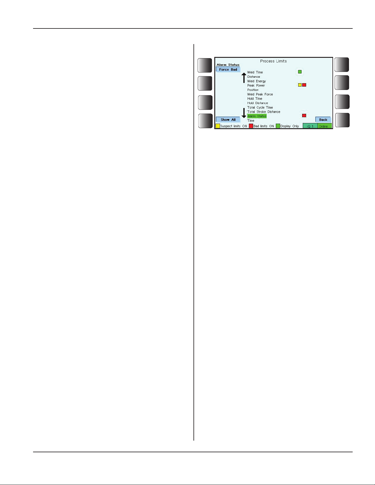
Process Limits, Continued from Previous Page
Alarm Status – This feature is included with the Part Lim-
its menu to compliment part cycle data. It does this to show
that a system alarm (www.dukane.com/us/DL_EasyAlarm.
asp) was active during the weld cycle for a particular part.
There are four options with Alarm Status – one that disables
the feature, and three other options that allow for the part
record to show that an alarm was active.
Options:
1) Disabled – Alarm Status is off. If an alarm
occurs, no signal will be generated for the welded part
record.
2) and 3) Force Bad, or Force Suspect – The
ultrasonic generator will provide a signal when a system
alarm activates. The operator chooses whether to
categorize the part under this circumstance as Suspect or
as Bad. Whatever designation is given to the part, it will
be carried on to become an item in the part record.
Figure 5-31 on the right shows with the red square
symbol, that Force Bad has been chosen as the option
for Alarm Status.
Section 5 - Operation
Figure 5–31 Process Limits - Alarm Status
4) Display – Whenever a system alarm happens,
the ultrasonic generator indicates this on the display's
Operate screen. A square green indicator appears
alongside the term Alarm Status. This is a visual cue
to the operator. The part record will not have this
information.
Time – This is the current time of day according to the iQ
generator timer.
Date – This is the current date according to the iQ genera-
tor timer.
Setup – This is the number of the current setup.
Dukane Manual Part No. 403-587-00
Process Limits, Continued
Page 65
Page 72
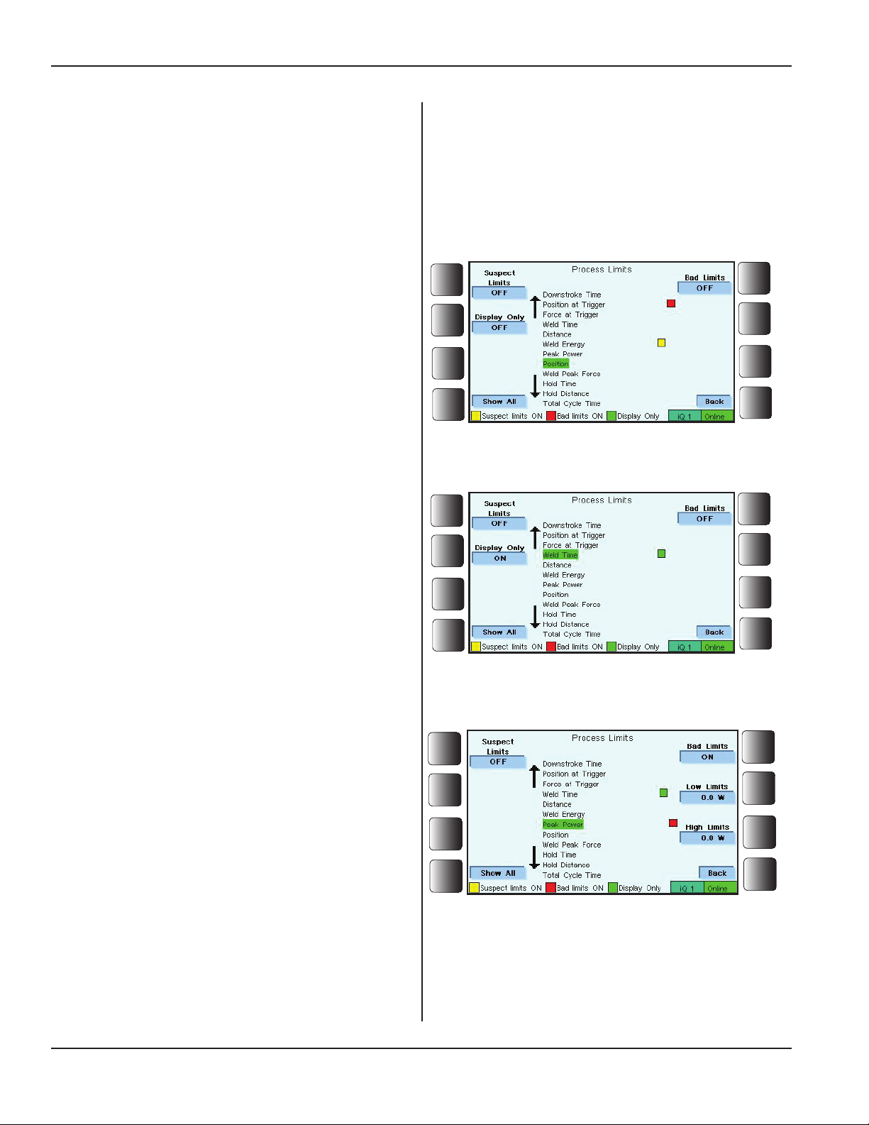
iQ Series Ultrasonic Generator/Power Supply, Servo Systems, ES User’s Manual
Process Limits, Continued from Previous Page
Data from Process Characteristics
Data from each weld cycle can be monitored through the
available process characteristics.
Programming choices for each characteristic are:
— No Display,
— Display Only,
— Bad Limits, and
— Suspect Limits.
No Display
Figure 5-32 shows that Position is the selected process
characteristic, and no choices have been made for that
characteristic. Weld characteristic is not displayed.
Figure 5–32 Process Limits - No Display
Display Only
Figure 5-33 shows Display Only was chosen for the Weld
Time process characteristic.
That process characteristic is displayed during normal operation on the Operate screen.
Bad Limits
This is also known as Bad Part Limits.
Figure 5-34 shows that Peak Power is the selected characteristic. Bad Limits are ON, and Low Limits and High
Limits need to be set.
The Bad part limits are used to establish boundaries that de-
ne unacceptable results for parts that are being processed.
If a bad limit is either not met or is exceed, the weld cycle
is ended immediately, and the operator is notied in these
ways:
• Two beeps are given (if buzzer is set to ON).
(See Buzzer, Page 80.)
• The iQ ES bad part output is activated.
• BAD is displayed in the part cycle data.
Figure 5–33 Process Limits - Display Only
Figure 5–34 Process Limits - Bad Limits
Page 66
Process Limits, Continued
Dukane Manual Part No. 403-587-00
Page 73
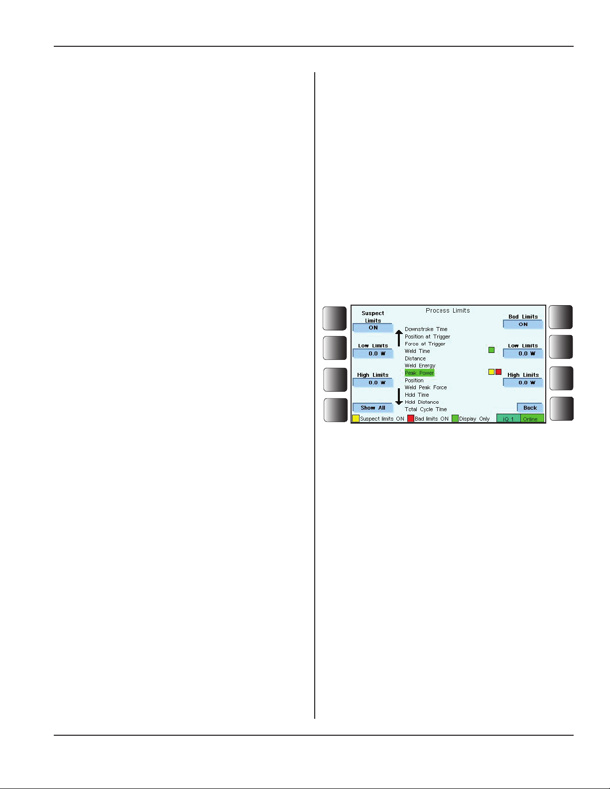
Process Limits, Continued from Previous Page
Suspect Limits
This is also known as Suspect Part Limits.
Suspect part limits detect out-of-limit conditions without ending the weld cycle. These limits are used when
process characteristics are grouped within a "gray area"
between good and bad. Parts can be sorted as good, bad,
and suspect. Suspect parts can be inspected manually.
Suspect limits can also be used as a form of pre-control
in applications where statistical process control methods
are being used.
When a suspect part limit has not been met or that it was
exceeded, the operator is notied in these ways:
• One beep is given (if buzzer is set to ON).
(See Buzzer, Page 80 .)
• The iQ ES suspect part output is activated.
• SUSPECT is displayed in the part cycle data.
Section 5 - Operation
In Figure 5-34 the selected characteristic is Peak
Power.
Both Suspect Limits and Bad Limits are ON for which
both Low Limits and High Limits need to be entered.
Part Cycle Data
The weld characteristics chosen to be displayed can be
seen in real time using the Operate Screen.
See OPERATE SCREEN on Page 84.
Show All
Notice that Figure 5-35 indicates there is an active soft
key for the selection: Show All.
Press the Show All key to display all the process characteristics.
Change your mind?
If you change your mind and decide not to
display all of the characteristics, press the
Show None soft key, to turn off the display
feature for all of the characteristics.
Figure 5–35 Process Limits - Suspect Limits
Dukane Manual Part No. 403-587-00
Page 67
Page 74
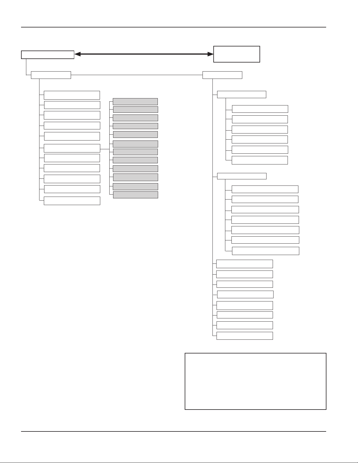
iQ Series Ultrasonic Generator/Power Supply, Servo Systems, ES User’s Manual
Utilities/Hardware
Process Utilities
Welder Name
Setup Control
Copy Setup
Erase Setup
Part Count Settings
Notes
Language
Base Units
Date Format
Time
Date
Setup Name
Horn
Booster
Fixture
Manual P1
Manual P2 / Hold
Dynamic Trigger
Down Speed / Flow Control
Mechanical Stop
HSC Setting
HSC Start Position
Pre-trigger / EOW Flags
Main Menu
Hardware Setup
Serial Port
Output Format
LF After CR
Output Mode
Baud Rate
Serial Limit Indicators
Serial Headers
System Status I/O
Auto Start Input
Auto Stop Input Enabled
J3 pin 4
J3 pin 5
Figure 5–36 Utilities/Hardware Menu Diagram
J3 pin 17
Output Duration
Restore System I/O Defaults
Adv Process Settings
Buzzer
Text Keyboard
Test at Power Up
Adv Trigger Settings
Network Settings
Servo Diagnostics
Restore Factory Defaults
NOTE
The list of available Process Utilities and
Hardware items depends on Security access level (See Table 4-II.) and on system conguration.
Page 68
Process Utilities, Continued
Dukane Manual Part No. 403-587-00
Page 75
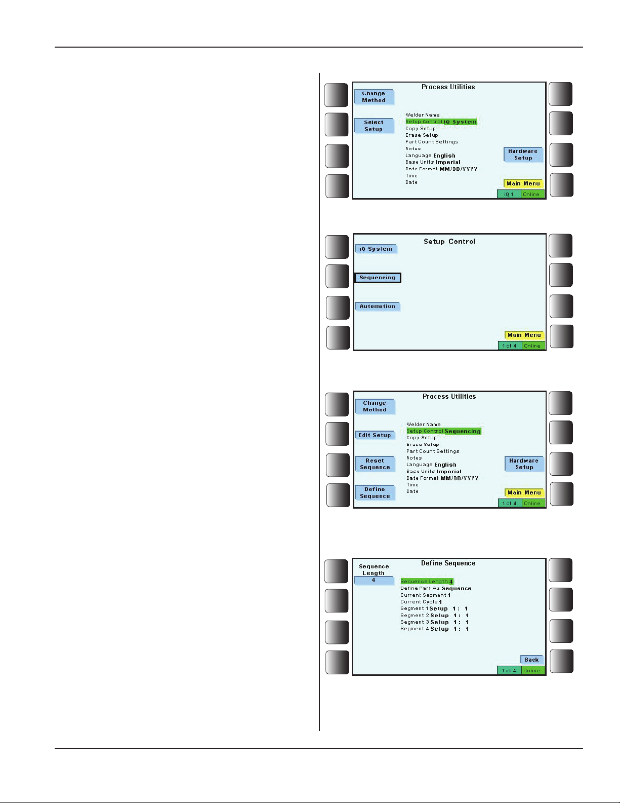
Process Utilities
Overview
Process Utilities provides setup management and part tracking tools. Notes are included to allow unique names to be
given to many setup components.
Setups and their components can be identied. This information can be used to recall setup conditions.
Figure 5-37 shows that, with the exception of Notes, there
are 10 utilities to consider. Review the brief descriptions of
these utilities below:
Welder Name
Use the virtual keyboard to give the welder its own iden-
tication.
Section 5 - Operation
Figure 5–37 Setup Control
Setup Control
Setup Control denes where control for setup originates:
with the iQ System, with Automation, or with Sequenc-
ing.
Select a Method of Control - When the soft key
Change Method is pressed, an image like the one shown
in Figure 5-38 appears.
Choose from three methods that dene where control for a
particular setup originates:
iQ System - Control originates through the iQ generator
and its program.
Sequencing - Control originates through the sequence
denition as programmed through the iQ generator.
See more on Sequencing in Appendix C.
Automation - Control originates from an external source
connected to the generator's System Input J2-8. The ultrasonics output remains activated only when the external
source applies a signal to J2-8.
Figure 5–38 Setup Control - Select a Method
Figure 5–39 Setup Control - Sequencing Chosen
If Sequencing is selected, then the screen shown in Figure
5-38 appears. Typically, Dene Sequence would be chosen.
Dening the sequence involves entering the information
suggested by Figure 5-40: Sequence Length, etc.
For more on Sequencing, go to Appendix C.
Dukane Manual Part No. 403-587-00
Figure 5–40 Dening the Sequence
Process Utilities Continued
Page 69
Page 76
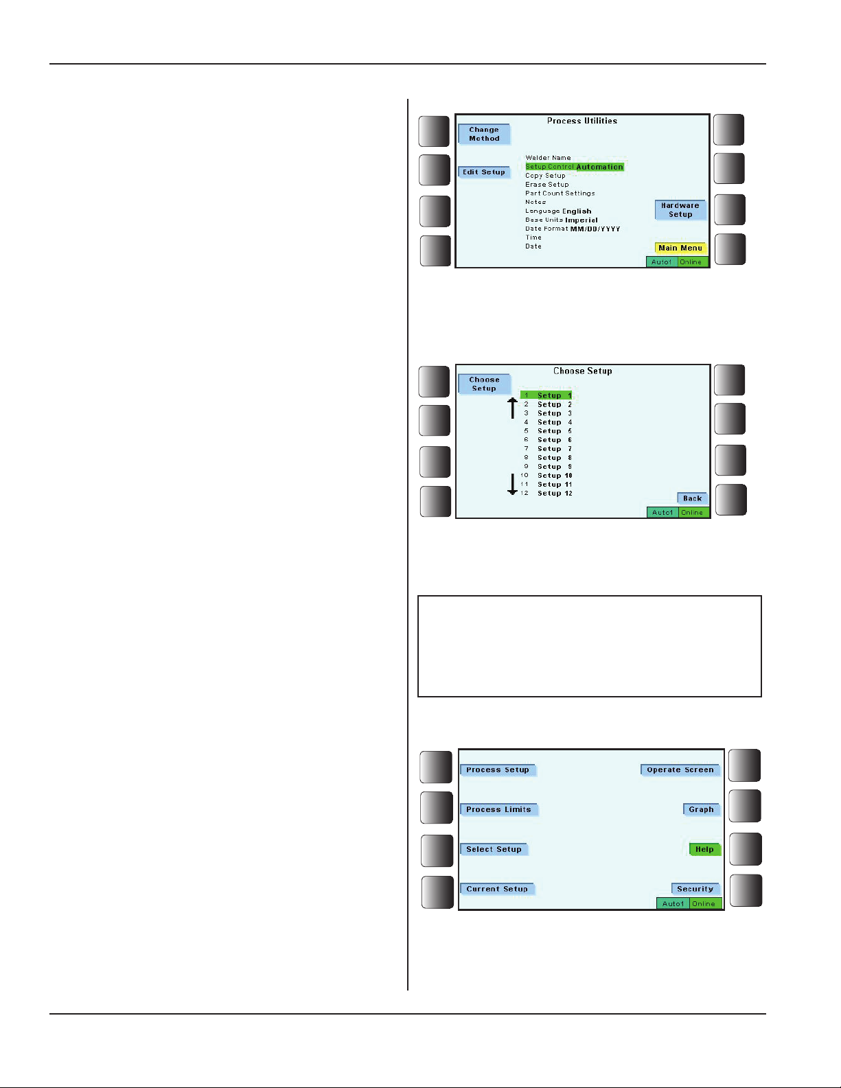
iQ Series Ultrasonic Generator/Power Supply, Servo Systems, ES User’s Manual
Process Utilities, Continued from Previous Page
Choose a Setup
Choosingasetupdependsontwofactors:
SetupControl,andSecurityAccess
Setup Control - Using Setup Control through the Process
Utilities menu, the three types of control deal with setup
selection in these ways:
- iQ System - Press the Select Setupsoftkey.
(SeeFigure5-37.)
Figure 5–41 Setup Control - Automation Selected
- Sequencing - Press the Edit Setupsoftkey.
(SeeFigure5-39.)
- Automation - Press the Edit Setupsoftkey.
(SeeFigure5-41.)
After pressing the Select Setup or Edit Setup key, a
Choose Setup screen like the one in Figure 5-42 to the
right is displayed.
Then, highlight a setup from the setup number list.
Next, press the Choose Setup soft key to conrm the
choice.
Security Access - If Security access has been established,
then menu access can be limited depending on what Security access level is active.
If the Setup Security is active, then the main screen would
look like it does in Figure 5-43 to the right.
To choose a setup in this case, press the Select Setup
soft key.
As with System Control, a list of setups is displayed.
Highlight a setup from the list and press Choose Setup.
Figure 5–42 Setup Control - Choose Setup
NOTE
Read the Security material starting on
Page 88 for more information.
Page 70
Figure 5–43 Select Setup - When Setup Security
Access is Active
Process Utilities, Continued
Dukane Manual Part No. 403-587-00
Page 77
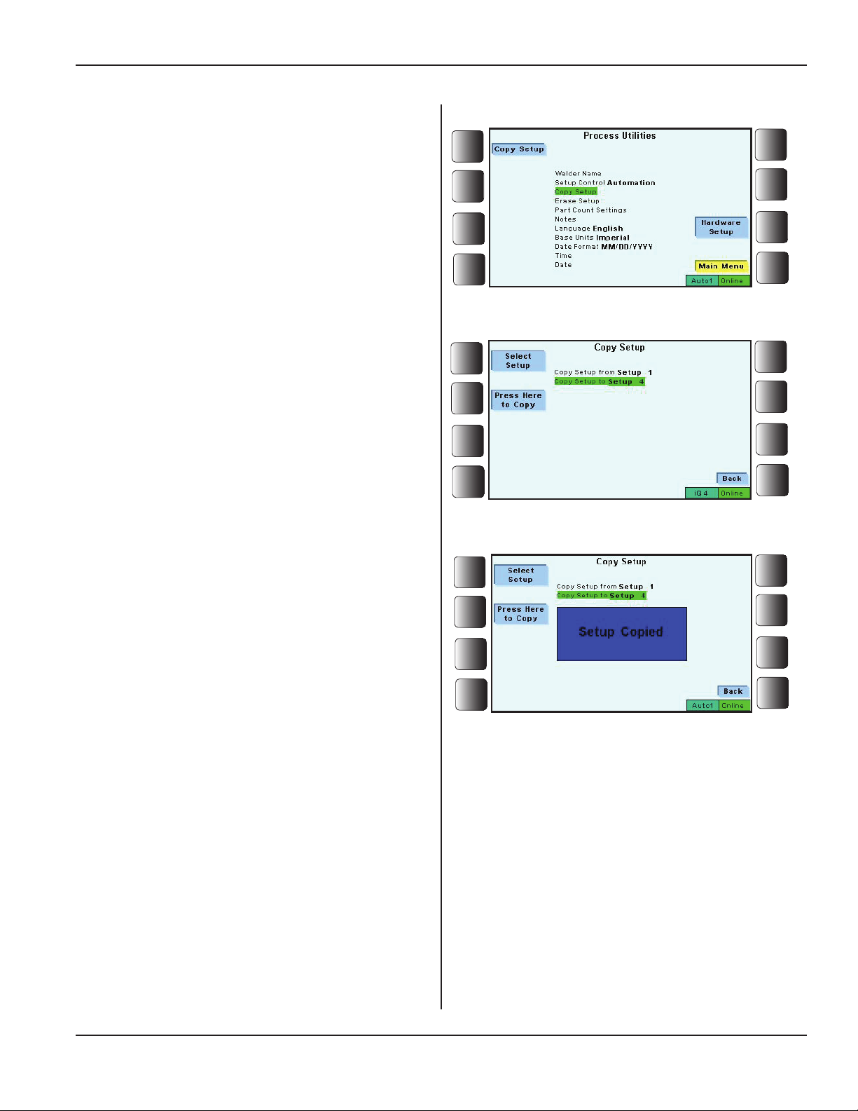
Process Utilities, Continued from Previous Page
Copy Setup
Thisfeatureallowsparametersfromonesetuptobe
copied toanothersetup.InFigure5-44totheright,
Copy SetupisselectedfromtheProcessUtilitieslist.
Press the Copy Setupsoftkey,andthedisplayshown
inFigure5-45appears.
Choosesetups:Copy From, and Copy To.
Then press the soft key, Press Here to Copy.
Section 5 - Operation
ThedisplaywillappearasitdoesinFigure5-46.
Figure 5–44 Copy Setup - 1
Figure 5–45 Copy Setup - 2
Dukane Manual Part No. 403-587-00
Figure 5–46 Copy Setup - 3
Process Utilities, Continued
Page 71
Page 78
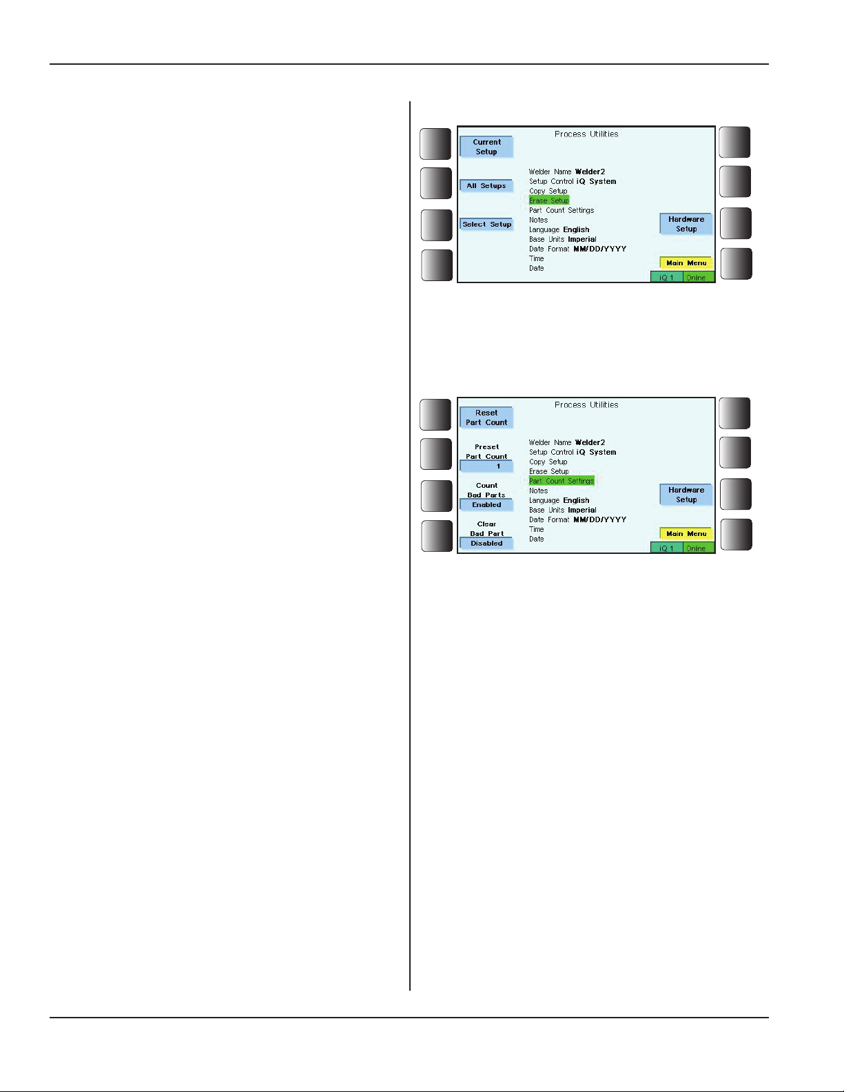
iQ Series Ultrasonic Generator/Power Supply, Servo Systems, ES User’s Manual
Process Utilities, Continued from Previous Page
Erase Setup
Setupparameterscanbeerasedforthecurrentsetup,or
forallsetups.Ascreenwillposethequestion,"Are you
sure you want to erase all setups?"AnswerYes or
Notoproceedwiththeeraseprocess.
See Figure 5-47 to the right.
Part Count Settings
This utility permits part count modication through its
three submenus:
Reset Part Count - Selecting this sets the part count
to zero (0). Therefore the next cycle completed would
create part number one (1).
Preset Part Count - Enter a number that starts the
part counter.
Count Bad Parts - Enable this to increment the part
count if a bad part occurs.
Clear Bad Part - Enable this to allow the operator to clear a Bad Part Limit Exceeded message
displayed on the front panel. Allowing the operator
to clear the bad part message will also reset the bad
part latch.
Figure 5–47 Erase Setup
See Figure 5-48 to the right.
Language
The language displayed by the front panel is made through
this utility.
Base Units
Select either Imperial or Metric units with this utility.
Date Format
The date utility allows for three ways to display the date:
• Month/Day/Year - MM/DD/YYYY
• Day/Month/Year - DD/MM/YYYY
• Year/Month/Day - YYYY/MM/DD
Time
This utility is used to set the current time.
Date
Entering the current date will be done in the date format
already chosen.
Figure 5–48 Part Count Settings
Process Utilities, Continued
Page 72
Dukane Manual Part No. 403-587-00
Page 79
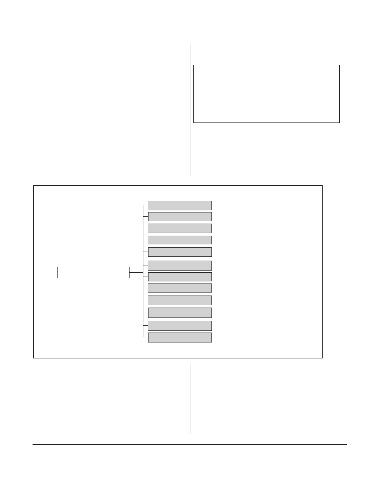
Process Utilities, Continued from Previous Page
Notes
It is important to document information about your
process. With the dozen components that make up Notes
for one setup, a customized record can be invaluable. See
Figure 5-49 below.
This utility makes it easy to name, or identify each of the
parameters using the virtual keyboard.
The Erase Name option also makes it easy to quickly
remove a name.
One benet to all of this is that future setup time will be
much shorter when trying to create the same or similar
setup.
Section 5 - Operation
NOTE
Although most of the Notes are related to
pneumatic systems, all of them are text
based. So they could include any type of
setup information.
Notes
Figure 5–49 Notes
Setup Name
Horn
Booster
Fixture
Manual P1
Manual P2 / Hold
Dynamic Trigger
Down Speed / Flow Control
Mechanical Stop
HSC Setting
HSC Start Position
Pre-trigger / EOW Flags
HSC = Hydraulic Speed Control
EOW = End of Weld
Dukane Manual Part No. 403-587-00
Process Utilities, Continued
Page 73
Page 80
iQ Series Ultrasonic Generator/Power Supply, Servo Systems, ES User’s Manual
Hardware Setup
Hardware Setup and its submenus can be used before
start-up, or during normal operation.
Typically Process Utilities have been set before Hard-
ware Setup is completed. Time, Date, Base Units,
Setup Control, and the other utilities have usually already
been established before Hardware Setup is programmed.
Serial Port
The rst group of hardware settings deals with the serial
port on the generator. These selections congure the iQ
generator's RS-232 port to transfer cycle data to a separate
computer. At the end of every cycle, the cycle data gets
sent out via the serial port. See Figure 5-50.
Output Format
Hardware Setup
Serial Port
Use the Output Format function to choose one of three
keyboard characters as the delimiter:
Comma - Ta b - Semicolon
Most database and spreadsheet programs are able to read
or save data in a delimited format. See Page 128 for more
detailed information about the serial data format.
LF after CR
Each line of output ends with a carriage return (CR). Some
devices automatically insert a line feed (LF) to advance
the paper, while others do not. Enabling the LF After CR
function makes it possible to insert a line feed at the end
of an output string.
Output Mode
Use Output Mode to determine the type of data that will
appear in the part record. Selections are dened below:
All - All parts are sent to the output device immediately
after the weld cycle.
None - No parts are sent to the output device.
Output Format
LF After CR
Output Mode
Baud Rate
Serial Limit Indicators
Serial Headers
Figure 5–50 Serial Port Selections
Good - Only good parts are sent to the output device.
Bad - Only bad parts are sent to the output device.
Suspect - Only suspect parts are sent to the output
device.
Bad and Suspect - All bad and suspect parts are sent
to the output device.
Page 74
Hardware Setup, Continued
Dukane Manual Part No. 403-587-00
Page 81

Hardware Setup, Continued from Previous Page
Baud Rate
Baud rate is the serial port output speed in bits per second.
Choose a baud rate appropriate for your output device.
Serial Limit Indicators
Limit indicators are characters that appear in front of displayed or printed part data indicating whether the data has
reached or exceeded an upper or lower limit.
The greater than sign (>) means that an upper limit Suspect
value has been exceeded.
Two greater than signs (>>) mean that an upper limit Bad
value has been exceeded.
The less than sign (<) means that a lower limit Suspect
value has not been reached.
Two less than signs (<<) mean that a lower limit Bad value
has been exceeded.
Section 5 - Operation
NOTE
Baud rate settings on both the sending
unit (iQ generator) and the receiving unit
(computer) must be the same for communication between the devices to work
properly.
Select Disable if the limit indicator might confuse a program that is running an SPC or data collection application.
Select Enable to allow use of the limit indicators.
Serial Headers
The user can send (print) serial header data each time the
Print soft key is pressed. The serial header data sent is
based on the "displayed" Process Limits, as dened in the
Process Limits screen.
Dukane Manual Part No. 403-587-00
Hardware Setup, Continued
Page 75
Page 82
Serial Port
iQ Series Ultrasonic Generator/Power Supply, Servo Systems, ES User’s Manual
Hardware Setup, Continued from Previous Page
System Status I/O
The next group of hardware settings (following the Serial
Port settings) deals with the generator's System Status I/O.
These six selections enable customizing of some of the iQ
generator's input and output signals. Figure 5-51 shows
these functions.
Auto Start Input
Use the Auto Start Input function to choose one of two
types of input that can originate the Auto Start signal:
Hardware Setup
System Status I/O
Auto Start Input
Auto Stop Input Enabled
Solid State, or Mechanical
Choosing Solid State will have no timing delay after the
activation of the Auto Input signal. This setting is typically used when a PLC controller is used to activate the
Auto Input.
Choosing Mechanical will have a congurable timing
delay after the activation of the Auto Input signal. This
setting is typically used when a relay is used to activate
the Auto Input.
Choosing Mechanical presents another choice. That is
Switch Debounce Time which is congurable to 5ms,
10ms or 25ms.
Auto Stop Input Enabled
This function can be disabled or enabled. The default setting is Enabled and set to End of Cycle.
When Auto Stop Input is enabled, the operator is prompt-
ed to choose the event that causes the auto stop:
Choose either, End of Weld, or End of Cycle.
J3 pin 4
J3 pin 5
J3 pin 17
Output Duration
Restore System I/O Defaults
Figure 5–51 System Status I/O Selections
• End of Weld - When Auto Stop is set to End of
Weld, the auto stop input signal terminates the weld but
not the complete weld cycle. If hold is enabled, it begins
at the trigger of this signal.
• End of Cycle - When Auto Stop is set to End
of Cycle, the auto stop input signal terminates the
complete weld cycle (hold is not executed, even if
enabled).
Page 76
Hardware Setup, Continued
Dukane Manual Part No. 403-587-00
Page 83
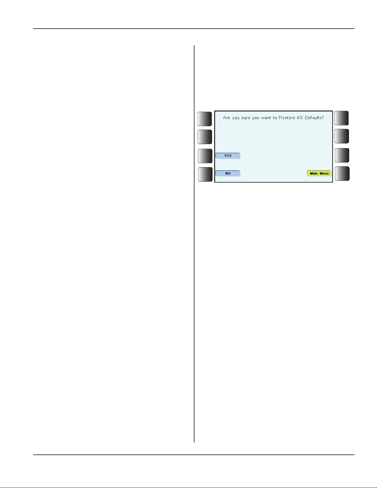
Hardware Setup, Continued from Previous Page
J3 pin 4
J3 represents the generator's output connector, and Pin
4 is programmable. The default setting is Servo Alarm.
It can be programmed to provide:
E-Stop Status, Overtemp Status, or Servo Alarm.
J3 pin 5
J3 represents the generator's output connector, and Pin
5 is programmable. The default setting is Home Servo.
It can be programmed to provide:
Hold Status, Incycle Status, Incycle no Afterburst,
or Home Servo.
J3 pin 17
Section 5 - Operation
J3 represents the generator's output connector, and Pin
17 is programmable. The default setting is Amplitude
Regulation.
It can be programmed to provide:
Amplitude Regulation, Teaching, or Servo Alarm.
Output Duration
Use the Output Duration function to decide on how long
the output signal should be:
Maintained, or 100ms Pulse
The default setting is Maintained.
Restore System I/O Defaults
Choose this function to restore the original system input/
output defaults.
Once Restore is chosen, a secondary screen is displayed
asking the operator to verify the choice:
Are you sure you want to Restore I/O Defaults?
Figure 5–52 Restore System I/O Defaults
See Figure 5-52 for the screen view.
Dukane Manual Part No. 403-587-00
Hardware Setup, Continued
Page 77
Page 84
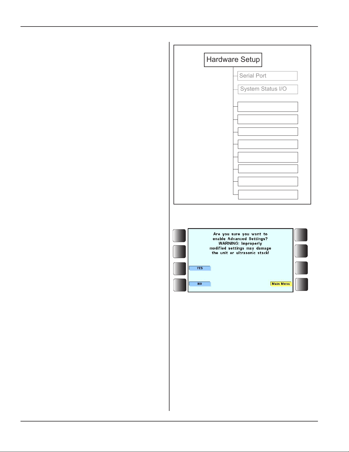
Hardware Setup
Serial Port
System Status I/O
iQ Series Ultrasonic Generator/Power Supply, Servo Systems, ES User’s Manual
Hardware Setup, Continued from Previous Page
Additional Hardware Settings
The next group of hardware settings (following the Serial
Port settings and the System Status I/O settings) deals with
various functions. These eight selections provide further
customizing of the iQ generator. Figure 5-53 diagrams
these selections.
Advanced Process Settings
Enabling Advanced Process Settings allows the opera-
tor to adjust a few of the higher level settings through the
Process Settings menus.
Adv Process Settings
Buzzer
To enable Advanced Process settings:
1. From the main menu select the Utilities/Hard-
ware soft key. In the Process Utilities screen
select the Hardware Setup soft key.
2. In the Hardware Settings screen scroll to Adv.
Process Settings which is located near the
bottom of the list, press the Enable soft key,
and then the YES soft key in the next screen.
Advanced process settings are now enabled.
Care should be taken when changing these settings because
the system could be damaged in some way.
Before changes are allowed, a warning screen displays an
alert. See Figure 5-54.
Descriptions of each of the settings are shown below.
• Free Run Frequency
Free run is the frequency at which the generator drives
the ultrasound output pulses until a valid feedback signal is detected. Typically this value should be below the
operating frequency of the stack.
• Frequency Tracking
Text Keyboard
Test at Power Up
Adv Trigger Settings
Network Settings
Servo Diagnostics
Restore Factory Defaults
Figure 5–53 Additional Hardware Settings Diagram
Figure 5–54 Advanced Process Settings Warning
When Enabled, at the end of each cycle the operating
frequency is applied to the Free Running Frequency setting. It's based on a 16 point average. Therefore, after 16
cycles, the actual operating frequency will be the Free
Running Frequency setting. If the generator has not been
cycled for a minimum of 5 minutes, the generator will
request that the stack be scanned in order to verify the
optimum Free Running Frequency setting.
For more information about Frequency Tracking, refer
to our Application Note 513 on the Dukane website at:
http://www.dukane.com/us/DL_ApplData.asp
Page 78
Hardware Setup, Continued
Dukane Manual Part No. 403-587-00
Page 85
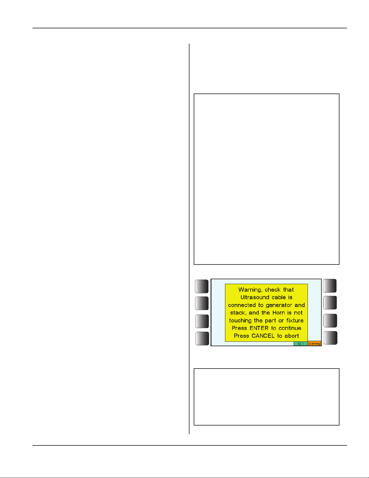
Hardware Setup, Continued from Previous Page
• Frequency Lock/Hold
When frequency lock and hold is disabled, the frequency
of the stack is tracked by changing the frequency of the
ultrasound driving pulses to match the actual operating
frequency of the stack.
When enabled the frequency of the feedback is tracked
until lock is achieved. Then it is ignored and the
ultrasound output remains at a xed frequency until the
end of the weld.
For more information about Frequency Lock/Hold, refer
to our Application Note 505 on the Dukane website at:
http://www.dukane.com/us/DL_ApplData.asp
• System Frequency Limits
Wide - In wide mode the upper and lower frequency
limits are set to the maximum and minimum allowed
frequencies for the generator. These values are dependent on the system frequency of the generator.
Normal - In Normalmode the upper and lowerfrequencylimitsequalthefreerunfrequency±500Hz.
Narrow- In Narrowmode the upper and lower frequencylimitsequalthefreerunfrequency±200Hz.
Manual-InManualmodetheusersetstheupperand
lowerfrequencylimits.Tobevalid,thesettings must
bewithinthemaximumand minimum values for the
generator and atleast 25Hz greater than the"upper"
freerunfrequencyand25Hzlessthan"lower"freerun
frequency.
Section 5 - Operation
NOTE
Why System Frequency Limits Modes
Might be Chosen
Wide - This mode is primarily used for
testing "bare" transducers (no booster or
horn attached).
Normal - This mode is the one most often
used covering a wide variety of horns.
Narrow - This mode is used when the
acoustic stack has known unwanted frequencies that are close to the main operating frequency.
Manual - This mode allows for a frequency range to include only frequencies
that are wanted, and excluding unwanted
frequencies.
• Scan Stack
With Advanced Process Settings enabled, to scan a
stack return to the Main Menu.
1. Select the Process Setup soft key to display the
Process Setup screen. Scroll to Adv. Process
Settings in the list and select the Adv. Process
Settings soft key.
2. Scroll to Free Run Frequency in the displayed
list and press the Scan Stack soft key.
A WARNING appears as shown in Figure 5-55 to
the right.
Dukane Manual Part No. 403-587-00
Figure 5–55 Scan Stack Warning
NOTE
For more detail on the Scan Stack feature
please refer to our website to download
Application Note 512 at http://www.du-
kane.com/us/DL_ApplData.asp
Hardware Setup, Continued
Page 79
Page 86
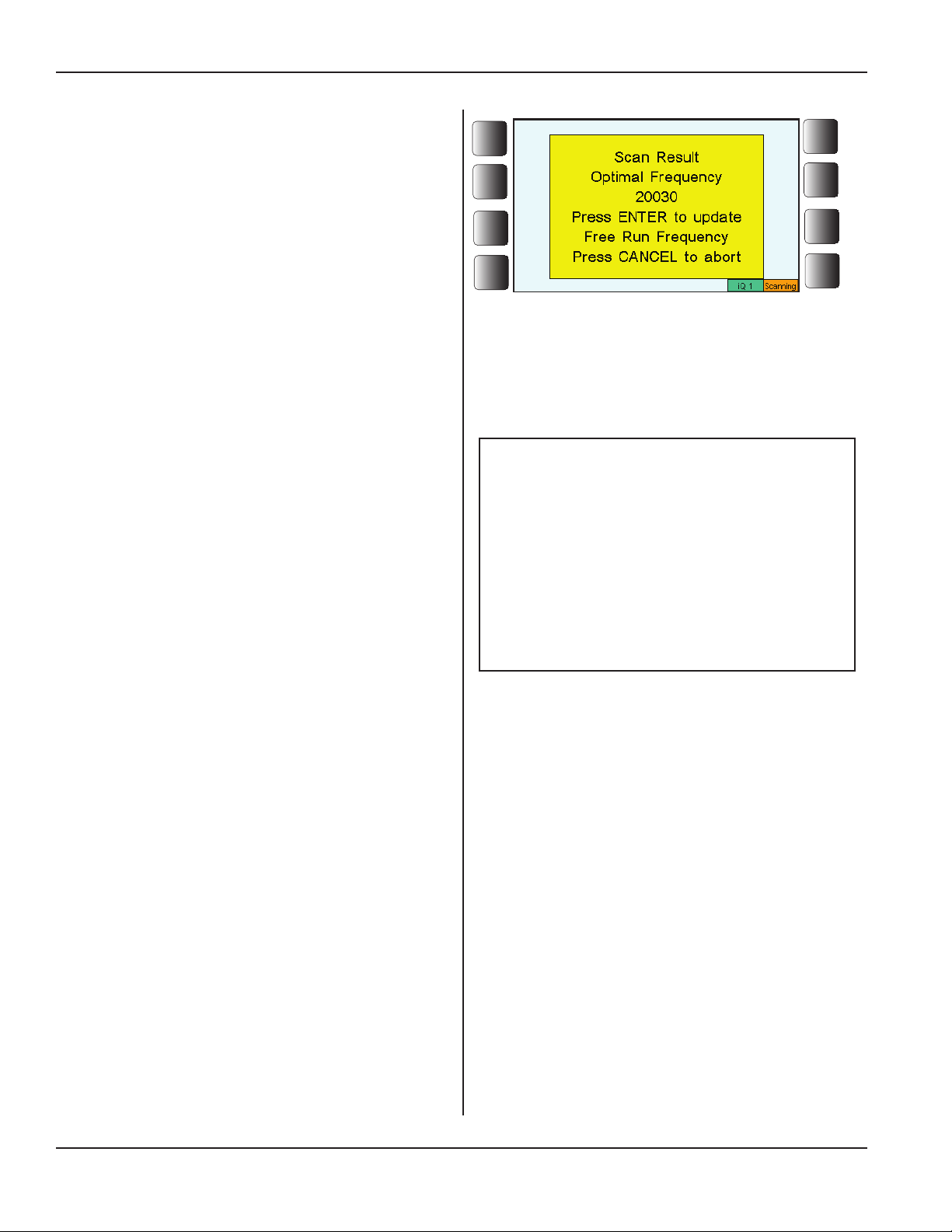
iQ Series Ultrasonic Generator/Power Supply, Servo Systems, ES User’s Manual
Hardware Setup, Continued from Previous Page
3. Press ENTER to continue.
The scan takes place with Amplitude, Power and
Frequency values are shown. Figure 5-56 illustrates the screen view after a successful scan.
• Ramp Up Time
Although the Ramp Up time is factory set, it is variable and can be adjusted to account for starting characteristics of a particular stack.
The Ramp Up setting depends on the generator load at
the start of a cycle.
The Ramp Up time increases the amplitude linearly,
in the programmed time period at the start of the weld,
from zero to the programmed amplitude level. The
stack is brought up to the operating amplitude smoothly, without shock stress.
• Ramp Down Time
Although the Ramp Down time is factory set, it is vari-
able and can be adjusted to account for characteristics
of a particular stack.
Ramp Down Time decreases the amplitude linearly to
zero in the programmed time period following the end
of the weld, when ultrasound is shutting off.
The stack is brought down from its weld amplitude,
reducing shock stress.
Figure 5–56 Scan Stack Results
Ramp Down Time extends the service life
of complex acoustic stacks by minimizing
stresses encountered during the process
of shutting off the ultrasound. It is especially recommended for very large horns,
or when the ultrasound is shut off in air.
NOTE
Ramp Down Time
• Restore Advance Process Defaults
Activate this feature, and it will restore all of the advanced process settings to their factory defaults.
Buzzer
Use the Buzzer function to turn the internal generator
buzzer on or off.
Disabled - The buzzer will not sound.
Enabled - The buzzer can signal two different
events. When the buzzer in enabled, it beeps once
when a suspect part occurs, and it beeps twice
when a bad part occurs.
The default buzzer setting is Disabled.
See Figure 5-57.
• Buzzer Top of Stroke - When enabled, buzzer
sounds when top of stroke is reached.
• Buzzer at Trigger - When enabled, buzzer sounds
when the trigger point is reached.
Hardware Setup, Continued
Page 80
Dukane Manual Part No. 403-587-00
Page 87
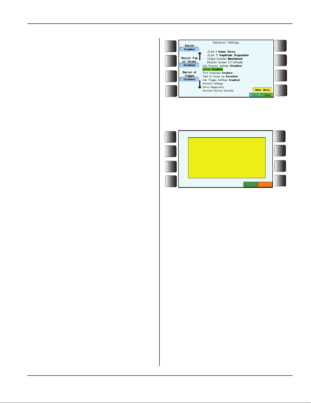
Hardware Setup, Continued from Previous Page
Text Keyboard
The virtual keyboard is enabled by default, and it pops up
when required. When disabled, the virtual keyboard will
not appear.
Test at Power Up
Each time the generator is powered On, the operator
will be prompted to execute a TEST of the ultrasonics
stack. The TEST can also be cancelled. The feature can
be disabled from the Hardware Settings screen. Test at
Power Up is Enabled by default. See Figure 5-58.
The “Test at Power Up” feature can also be cancelled by
activating the “System Latch Reset” input (J2-12).
Advanced Trigger Settings
When Advanced Trigger Settings are enabled, basic trigger
settings are enhanced.
For example, in the Process Setup menu, when Force is
the Trigger Type, Pre-trigger is an advanced trigger function and is added to rene the Force selection. See Figure
5-59 on the next page where basic and advanced trigger
functions are illustrated.
Network Settings
The Network Settings screen as seen in Figure 5-59 has
ve elements:
1. DHCP - These initials stand for Dynamic Host Con-
guration Protocol. The protocol was established for
assigning dynamic IP addresses to devices on a network.
Figure 5–57 Buzzer Enabled
Test at Power Up is enabled.
Please clear area around the
stack and press Test button
for 1 second before welding
parts.
Press CANCEL to abort.
Figure 5–58 Test at Power Up
Section 5 - Operation
iQ 1
Test
DHCP should be enabled if connecting multiple generators when using an Ethernet router or switch.
DHCP can be enabled or disabled depending on customer
requirements.
2. IP Address - This Internet Protocol address is a num-
ber unique to a piece of equipment acting as an identier
when the equipment is connected to a network. An IP
address is specied when a static IP is required.
3. Network Mask - Automatically assigned by the
DHCP server.
4. Gateway Address - Automatically assigned by the
DHCP server.
5. Network Link - This shows the status of the connection to a network:
Linked - This displays the speed of the network connection.
Not Linked - Down
Dukane Manual Part No. 403-587-00
Hardware Setup, Continued
Page 81
Page 88
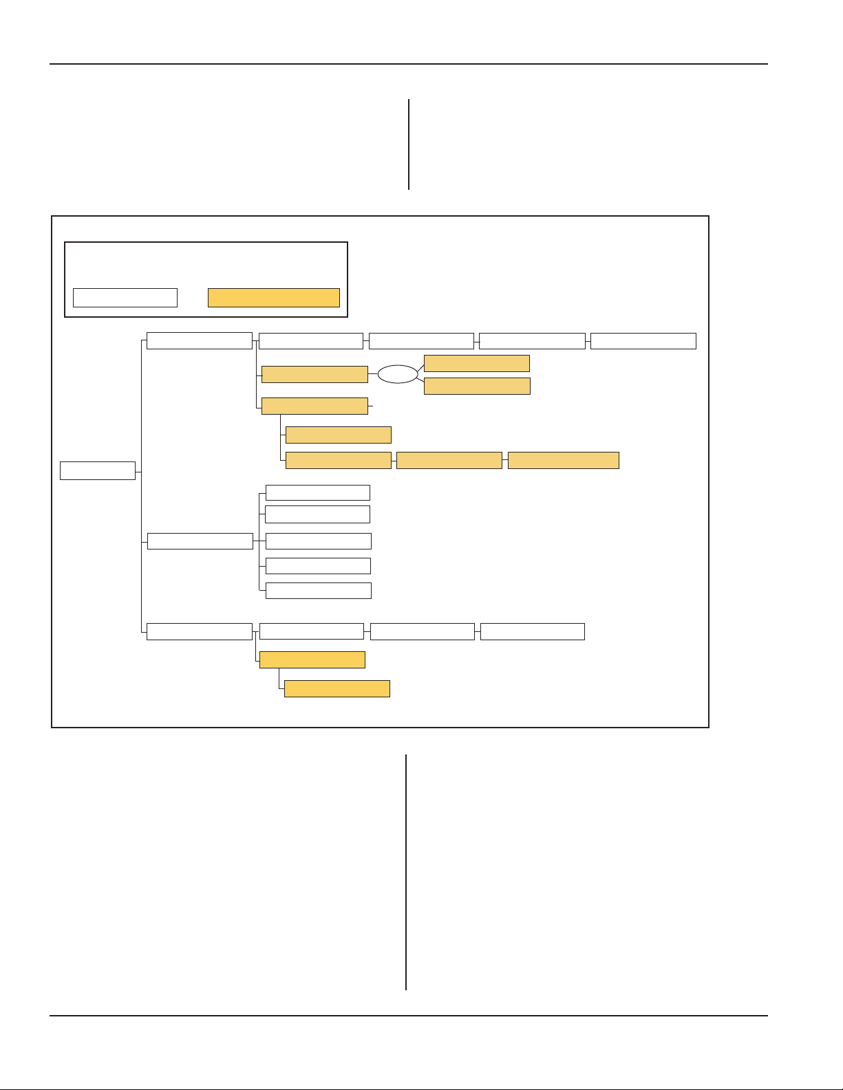
iQ Series Ultrasonic Generator/Power Supply, Servo Systems, ES User’s Manual
Hardware Setup, Continued from Previous Page
Servo Diagnostics
Reserved for use by Dukane personnel, these diagnostics
monitor servo inputs, test status, performance and cycles.
KeytoTriggerFunction:
Basic Trigger Function Advanced Trigger Function
Trigger Type
Force
Power
Position
Force at Trigger Max Trigger Time
Pre-trigger
Trigger Delay Not a choice if Pre-trigger is Enabled
Disabled
Delay by Distance
Trigger Power
Max Trigger Time
Start Amplitude
Sensing Start Position
Sensing Speed
Max Trigger Time
Trigger Delay
Disabled
Enabled
Trigger Position
Pre-trigger Amplitude
Pre-trigger Position
Trigger Delay Distance
Sensing Start Position
Max Trigger Delay Time
Teach Trigger Position
Sensing Speed
Figure 5–59 Trigger Function - Basic and Advanced
Page 82
Hardware Setup, Continued
Dukane Manual Part No. 403-587-00
Page 89
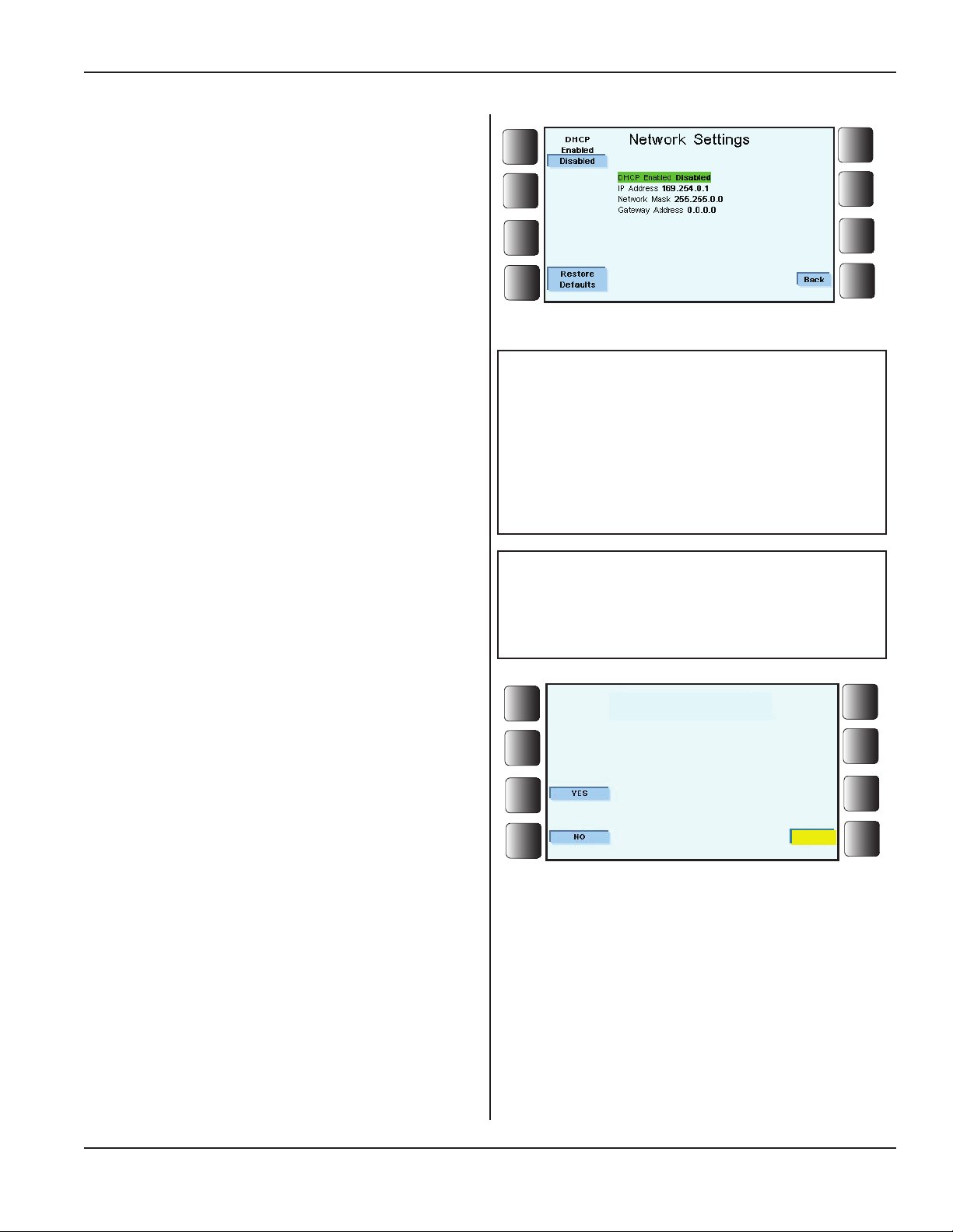
Hardware Setup, Continued from Previous Page
Restore Factory Defaults
Choose Restore Factory Defaults when restoring the
generator software to the factory default settings.
Section 5 - Operation
Before this is allowed, however, an intermediate screen
questioning the action appears. See Figure 5-61.
Important:
Performing a Restore Factory Defaults can not
be reversed.
Network Link Down
Figure 5–60 Network Settings
NOTE
If the user is directly connecting to a laptop
or PC, the PC's IP address should be set
to 169.254.0.x (x must be 2-255).
The (x_ in the computer's IP address can
not be the same x as in the generator's IP
address.
NOTE
Network Settings are maintained even
after a Restore Factory Defaults.
Are you sure you want to Restore Factory Defaults?
Figure 5–61 Restore Factory Defaults?
Main Menu
Dukane Manual Part No. 403-587-00
Page 83
Page 90
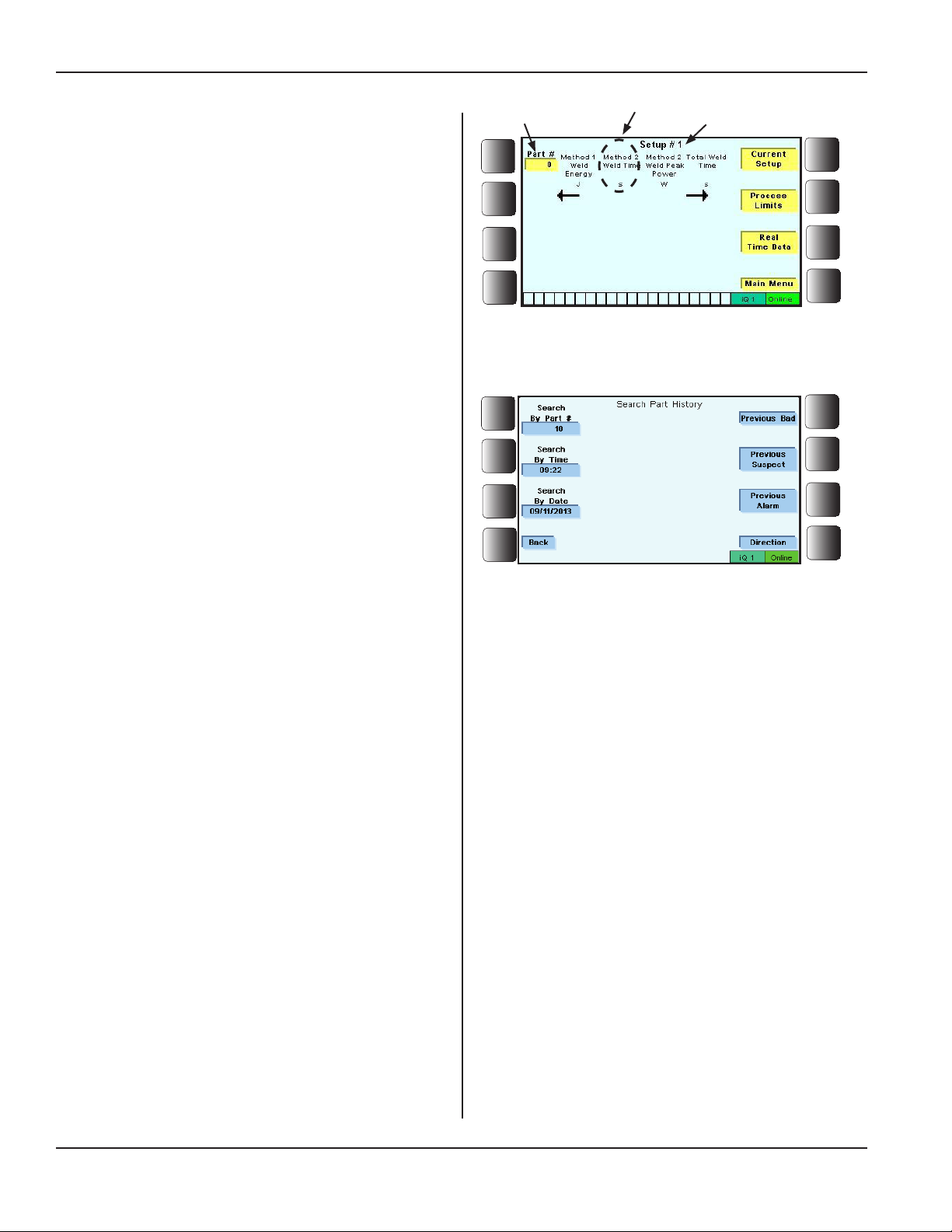
iQ Series Ultrasonic Generator/Power Supply, Servo Systems, ES User’s Manual
Operate Screen
The Operate screen displays weld cycle data in real time.
Figure 5-62 shows the main Operate screen.
Process characteristics listed below the setup
name are the ones chosen (as process limits) to be
displayed or programmed.
Part # in the upper left corner of the Operate screen records
the running total of processed parts.
When a minimum of 10 parts have been processed, press
the soft key next to the total number of parts box. The next
screen Search Part History appears, and allows searches
by Part Number, Time, Date, Previous Bad, Previous Suspect, and Previous Alarm.
Part Number History
Search by Part # - Press this soft key to search for a
specic part number in the cycle data.
Total Parts
Processed
Figure 5–62 Main Operate Screen
Process
Characteristic
Setup Name
Pressing the Part # soft key displays a search screen after
a minimum of 10 parts are in the cycle data.
Search by Time - Press this soft key to search for a part
know to have been welded at a specic time in the cycle
data.
Search by Date - Press this soft key to search for a
specic part welded on a specic date in the cycle data.
Previous Bad - Press this soft key to search for a
previously welded bad part in the cycle data. Pressing
the soft key again will continue searching for the next
previously welded bad part.
Previous Suspect - Press this soft key to search for a
previously welded suspect part in the cycle data. Pressing
the soft key again will continue searching for the next
previously welded suspect part.
Previous Alarm - Press this soft key to search for a
previously part that had an alarm in the cycle data.
Pressing the soft key again will continue searching for the
next previous part that had an alarm.
Figure 5–63 Part Number Screen
Direction - Press this soft key to change the direction of
the search from previous cycle data parts to next cycle
data parts.
Page 84
Dukane Manual Part No. 403-587-00
Page 91
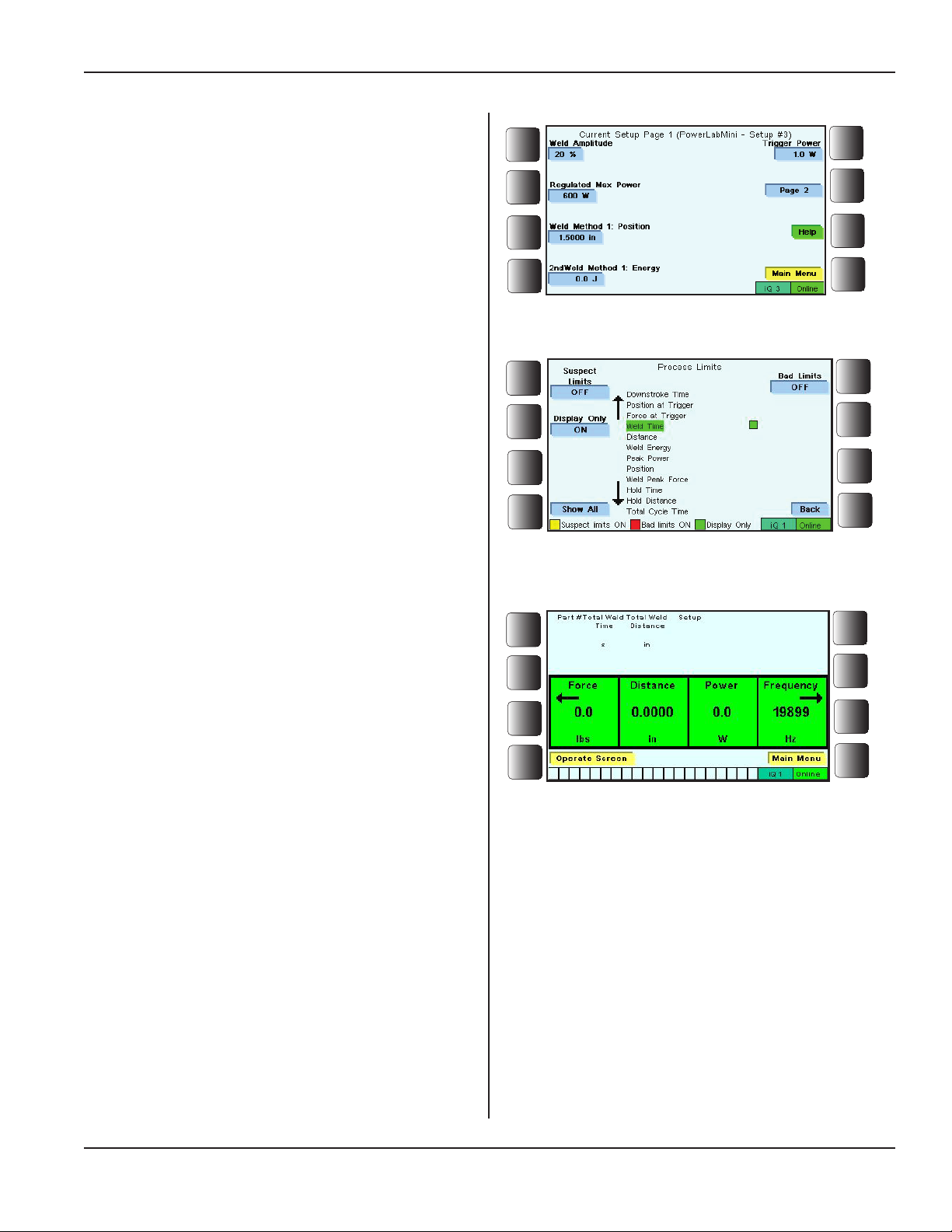
Current Setup
While viewing the Operate screen, (or from the Main
Menu), press the soft key next to Current Setup, and a
view similar to the one shown in Figure 5-64 will appear.
This is usually a multiple page (display) list of the main
parameters that were set for the current setup.
Process Limits
Press the soft key next to Process Limits, and the process
limits list, similar to the one shown in Figure 5-65 is dis-
played. Adjustments to the list of process characteristics
can be made easily.
Press Back when nished making adjustments to the list of
process characteristics, and once again the main Operate
screen will be shown.
Section 5 - Operation
Figure 5–64 Current Setup
Figure 5–65 A Process Limits List
Real Time Data
See Figure 5-66.
Press the soft key next to Real Time Data, and the display
changes to show press characteristics for the current setup
and weld cycle.
The possible characteristics are: Force, Distance, Power,
Frequency, and Speed.
Characteristicsdisplayeddependonsystemconguration.
Figure 5–66 Real Time Data
Dukane Manual Part No. 403-587-00
Page 85
Page 92
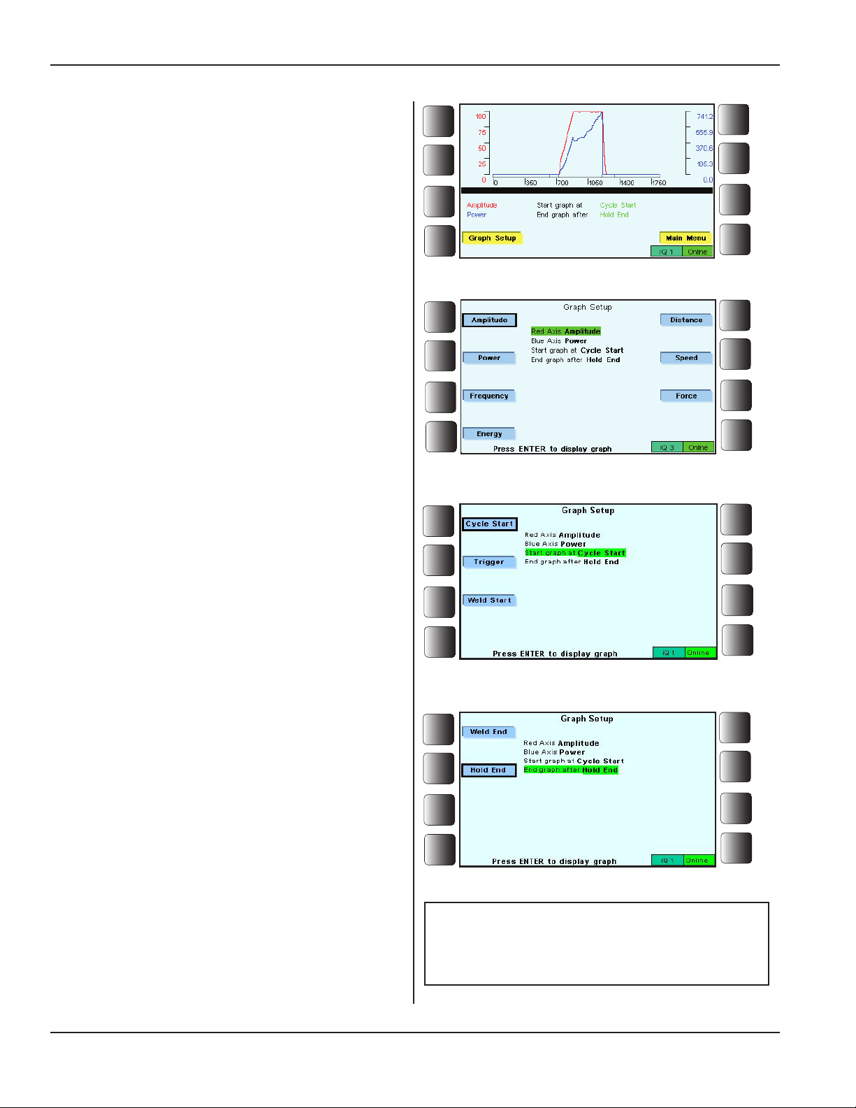
iQ Series Ultrasonic Generator/Power Supply, Servo Systems, ES User’s Manual
Graph
The generator is factory programmed to provide graphs
with amplitude and power as the vertical axes.
Figure 5-67 shows the beginning graph screen.
Graph Setup
Figure 5-68 shows the graph setup screen used when selecting parameters for the two vertical axes of the graph.
(The horizontal axis represents time.)
Select from these parameters:
Amplitude, Power, Frequency, Energy, Distance,
Speed, Force
1. Red Axis - Press one active soft key representing
the parameter for the vertical (red) axis. This axis is
on the left side of the graph.
Figure 5–67 Graph Screen
2. Blue Axis - Press one active soft key representing
the parameter for the vertical (blue) axis. This axis is
on the right side of the graph.
Figure 5-69 shows the graph setup screen used to choose
a starting point for the graph.
3. Choose one of the active soft keys representing
the event that starts the graphing procedure.
The events are:
Cycle Start, Trigger, or Weld Start.
Figure 5-70 shows the graph setup screen used to select
the end point for the graph.
4. Chose one of the active soft keys representing one
of two events that after they have nished, the graph-
ing procedure will come to an end. The events are:
Weld End, Hold End
Figure 5–68 Graph Axis Setup Screen
Figure 5–69 Start Graph at Setup
Page 86
Figure 5–70 End Graph at Setup
NOTE
When in the graph setup screen, press
ENTER to return to the graph screen.
Continued
Dukane Manual Part No. 403-587-00
Page 93
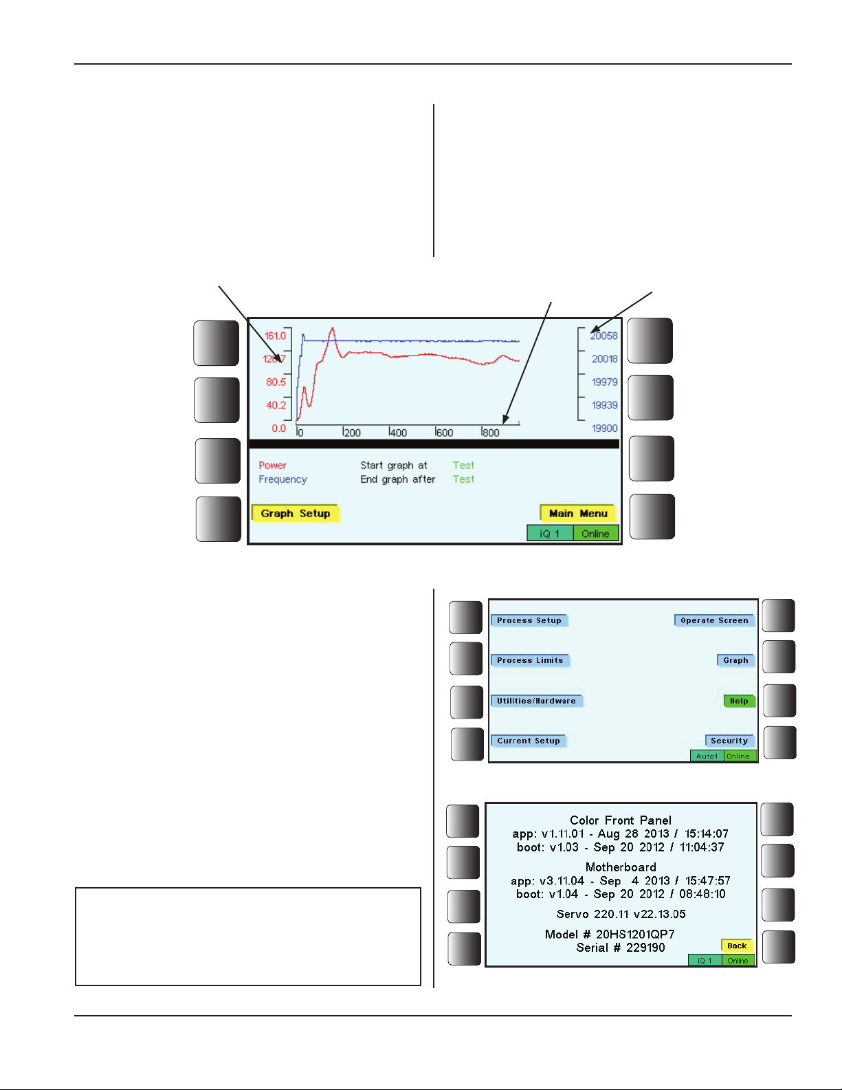
Graph, Continued from Previous Page
Completed Graph
The gure below shows a completed graph.
This particular image resulted after pressing the TEST key.
Section 5 - Operation
Red Vertical Axis,
Power
Figure 5–71 Example Graph Following Test
Help
From the main screen, (Figure 5-72 to the right) press the
soft key next to Help.
Horizontal Axis,
Time
Blue Vertical Axis,
Frequency
This will produce a screen that gives information about your
generator, including model and serial numbers.
An example of this screen is seen in Figure 5-73.
NOTE
Color Front Panel v1.11.02 will also display
the network IP Address in the bottom left
corner of the HELP screen.
Dukane Manual Part No. 403-587-00
Figure 5–72 Locating Help on the Main Menu
Figure 5–73 Help Screen Example
Page 87
Page 94
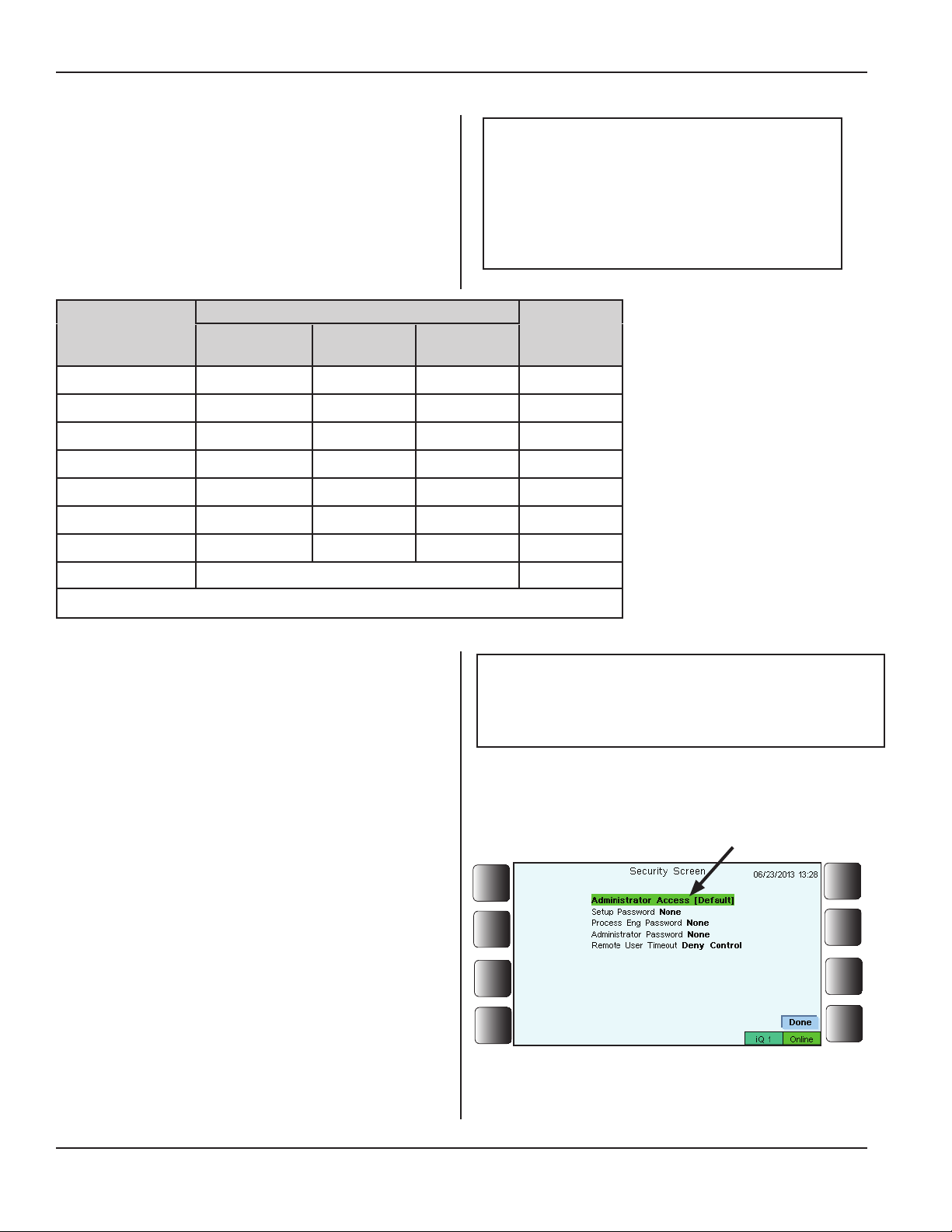
iQ Series Ultrasonic Generator/Power Supply, Servo Systems, ES User’s Manual
Security
The Security menu choices control access to the programming menus by using individual logins for three levels:
Administrator, Process Engineer, and Setup.
The table below shows what access each security level
has. In addition the Operator column shows the access a
generator operator would have when the three levels of
control are in use.
Main Menu Item
Graph Screen
Operate Screen
Process Setup
Process Limits
Process Utilities
Hardware Setup
Current Setup
••
= Select Setup is available.
Persons needing an individual login.
Administrator
Process
Engineer
O O O O
O O O O
O O X X
O O X X
O O O •• X
O X X X
O O O X
O=AccessX=NoAccess
NOTE
Operator - Usually the operator does
not need to use the Security feature.
Typically an operator only monitors the
weld cycle using the Operate and Graph
screens.
Operator
Setup
Table 5 - I Security Access to Main Menu Item
Remote User Timeout
The purpose of this option of the Security menu is to
yield (allow) or deny access to the programming features
of the iQ generator under certain conditions.
This feature is most useful when a remote user (using iQ
Explorer II software) and a user at the generator might
both want to control the generator. A request for control
(by either user) shows on the generator display and on the
remote computer display. (See Figure 5-85, Page 92.)
If no response is given (by either user) to this request
within 30 seconds, then in whatever state the generator
had been left (Deny Control or Yield Control) before the
request for control, that is the state in which the generator
will continue to operate.
Example: A remote user requests control of the generator, and no one is at the generator to respond to the
request. If the generator had been programmed to yield
control, then after 30 seconds, the remote user would
have control.
NOTE
The default setting for Remote User Timeout
is Deny Control.
Access (to program the generator),
is assigned to the Administrator as
a default setting if no passwords
have been set.
Figure 5-74 Security Screen - No Passwords Set
Continued
Page 88
Dukane Manual Part No. 403-587-00
Page 95
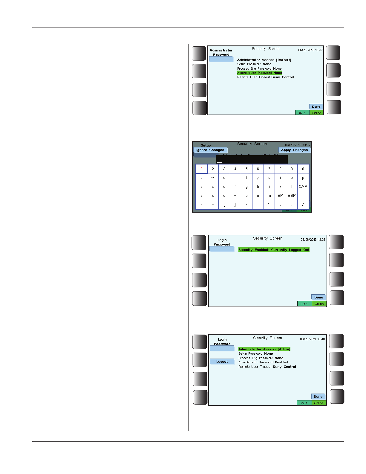
Security, Continued from Previous Page
Using Security
Enabling Passwords for the First Time
1. Press the Security soft key. The Security Screen
appears as shown in Figure 5-74. The word None
means no passwords have been enabled or set.
In the example that follows, three passwords will be set:
First, for the Administrator, then for the Process Engi-
neer, and nally, for the Setup password.
Section 5 - Operation
2. Select, Administrator Password None in the list.
(The selected phrase is highlighted in green.)
The soft keys Administrator Password, and Done are
now displayed. See Figure 5-75.
3. Press the Administrator Password soft key, and the
alphanumeric virtual keyboard is displayed. This is shown
in Figure 5-76.
Enter a password of up to 15 characters.
Press Apply Changes when nished.
The next screen to appear looks like Figure 5-77.
Because the screen message says, Security Enabled:
Currently Logged Out, the Administrator must enter the
Login Password to activate access to security features.
Figure 5-75 Security Screen - Administrator Password
Selected
Figure 5-76 Virtual Keyboard
Once the Administrator password has been entered, the
screen appears as shown in Figure 5-78.
Note the change in the Security Screen from what is
seen in Figure 5-75. The Administrator Password has
been Enabled. Also Administrator Access is followed
by [Admin] showing that the Administrator has current
security access.
Login is complete for the Administrator.
Dukane Manual Part No. 403-587-00
Figure 5-77 Security Screen - Currently Logged Out
Figure 5-78 Security Screen - Administrator Access
Enabled
Continued
Page 89
Page 96
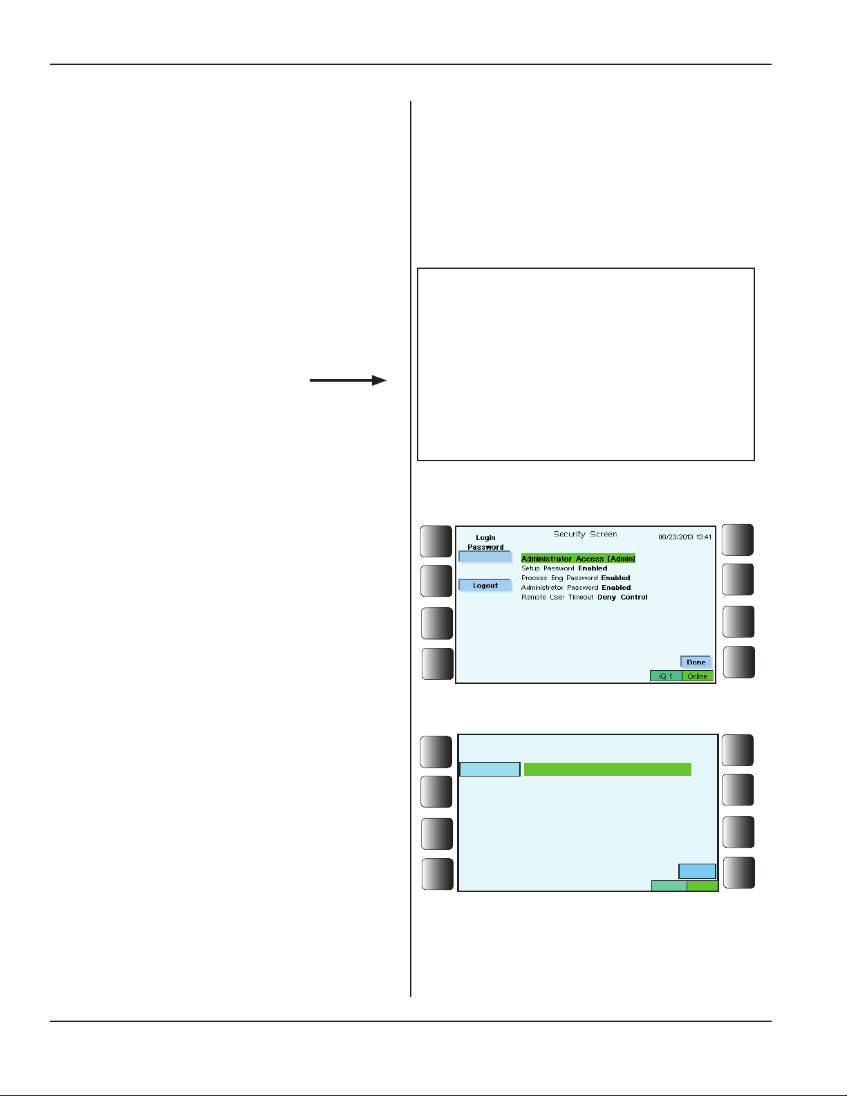
iQ Series Ultrasonic Generator/Power Supply, Servo Systems, ES User’s Manual
Security, Continued from Previous Page
At this point the Administrator typically has four options:
• Logout - Press the soft key next to Logout, and
the Administrator will be logged out. None of the security
levels will be active.
• Done - Press the soft key next to Done to exit
and return to the main menu.
• Erase - Select Administrator Password En-
abled in the list. Press the Erase soft key, and the password
will be erased or,
• Continue enabling passwords.
If the Login Password soft key is pressed,
For additional passwords, complete Steps 4 and 5.
and a wrong password is entered, a
screen prompt indicates an incorrect
Also, please read the NOTE to the right.
password has been entered. The next
screen shows that the person has been
logged out. Restart the login process to
activate the security features.
NOTE
4. After enabling the Administrator password, the next
level to activate is usually Process Engineer.
Select, Process Eng Password None in the list.
Next, Select Process Eng Password with the upper
left soft key, and the alphanumeric virtual keyboard is
displayed. Enter a password of up to 15 characters.
Press Done when nished.
5. After setting the Administrator password and the Pro-
cess Engineer Password, select the line: Setup Password
None. Set a password for Setup repeating the methods
already explained.
Figure 5-79 shows the Security Screen when all three
passwords have been enabled.
Press the Logout key.
Figure 5-80 shows that the Administrator has logged out.
Login Password and Done are choices.
Press the soft key next to Login Password to login.
Press Done to exit and return to the main menu.
Figure 5-79 Security Screen - Passwords Enabled
Login
Password
Figure 5-80 Security Screen - Logged Out
Security Screen
Security Enabled: Currently Logged Out
06/24/2013 13:30
Done
iQ 1
Online
Page 90
Continued
Dukane Manual Part No. 403-587-00
Page 97
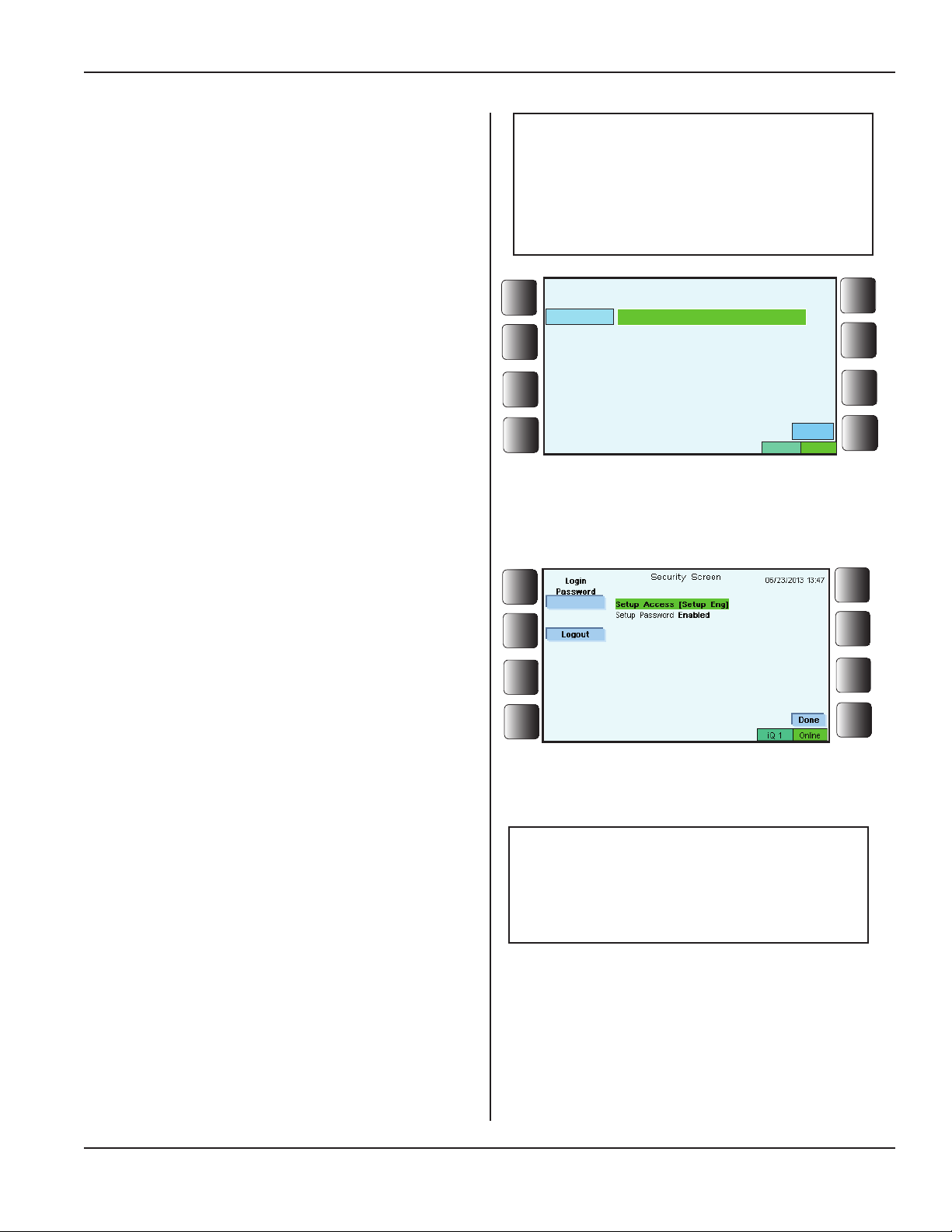
Security, Continued from Previous Page
Section 5 - Operation
After Passwords are Enabled
Once passwords have been enabled as described on the
previous page, generator menu access is controlled.
For each person assigned a password, please use the
four steps detailed below for the login/logout procedure.
1. Press the soft key for Security. The Security Screen
appears as shown in Figure 5-81.
The previous user has logged out.
2. Any of the three passwords (Setup, Process Eng,
or Admin) that were already enabled can be entered.
In this case, the Setup password will be entered, and the
screen then will resemble what is shown in Figure 5-82.
NOTE
When using the Security feature,
only one person can be logged in at
a time. Each login session must end
with a logout.
Login
Password
Figure 5-81 Security Screen - Logged Out
Security Screen
Security Enabled: Currently Logged Out
06/24/2013 13:30
iQ 1
Done
Online
The Security Screen indicates that Setup Eng controls
access to the generator.
3. Press Done to continue working with the available
menus.
Available menus for Setup Eng are: Select Setup,
Operate Screen, Graph, Help, and Security.
4. When nished working with the generator, press
Security to get to the Security Screen again. Then press
the soft key next to Logout to quit.
5. Finally, press Done so that the main menu screen is
displayed when the session is complete.
Figure 5-82 Security Screen - Setup is Logged In
NOTE
Refer to Table 5-I for a guide to the
levels of access that are possible
when using the Security function.
Dukane Manual Part No. 403-587-00
Continued
Page 91
Page 98
iQ Series Ultrasonic Generator/Power Supply, Servo Systems, ES User’s Manual
Security, Continued from Previous Page
Other Security Prompts
With login passwords in use, the levels of access to the
generator are established.
Security prompts - like the samples seen in Figures
5-83 and 5-84 to the right - are displayed when access
to menu features has been limited.
Remote User Request for Control
Setup Access
Required
Please Log In
Figure 5-83 Security Prompt for Process Engineer
Access
Process Eng Access
Required
Please Log In
Figure 5-84 Security Prompt for Setup Access
The screen shown in Figure 5-85 to the right displays
when a remote user wants to control the generator.
Access can be granted by pressing the Yield Control
soft key.
Deny access by pressing the Deny Control soft key.
Forgotten Password?
Contact Dukane if the password has been forgotten.
See Section 10 - Contacting Dukane.
Figure 5-85 Remote User Seeking Control
Page 92
Dukane Manual Part No. 403-587-00
Page 99
Section 5 - Operation
Set-up Guidelines
The iQ SeriesESgeneratorisshippedwiththedefaultsettingsshowninthetablebelow.
Default Servo Settings
Frequency 15kHz 20kHz 30kHz 40kHz 50kHz
Initiate Mode Manual Manual Manual Manual Manual
Top of Stroke 0.0000 0.0000 0.0000 0.0000 0.0000
Weld Amplitude 90% 90% 90% 90% 90%
Advanced Settings Disabled Disabled Disabled Disabled Disabled
Trigger Type Force Force Force Force Force
Trigger Force (lbs) 75 50 25 15 5
Max. Trigger Time 5.000 5.000 5.000 5.000 5.000
Sensing Speed 0.0500 0.0400 0.0400 0.0300 0.0200
Weld Primary Method Distance Distance Distance Distance Distance
Weld Distance 0.0150 0. 0100 0.0075 0.0050 0.0050
Max. Weld Time 2.000 2.000 2.000 2.000 2.000
Weld Secondary Method Disabled Disabled Disabled Disabled Disabled
Weld Prole Constant Constant Constant Constant Constant
Weld Prole Speed 0.0500 0.0400 0.0300 0.0200 0.0200
Melt Detect Enabled Enabled Enabled Enabled Enabled
Force Drop % 5% 5% 5% 5% 2%
Dynamic Hold Method Disabled Disabled Disabled Disabled Disabled
Static Hold Method Time Time Time Time Time
Static Hold Time 1.000 0.700 0.500 0.300 0.300
Afterburst Disabled Disabled Disabled Disabled Disabled
Travel Limit Based on
Press Stroke
Based on
Press Stroke
Based on
Press Stroke
Based on
Press Stroke
Based on
Press Stroke
Table 5-II Default Settings - Process Setup
Dukane Manual Part No. 403-587-00
Page 93
Page 100

iQ Series Ultrasonic Generator/Power Supply, Servo Systems, ES User’s Manual
Changing Default Settings
From the Main Menu, go to Process Setup. Each
of the items shown in the table above is listed as a
Process Setup submenu item and can be customized
for your process. Refer to Pages 50-61 for more
information about working with the Process Setup
menu.
Page 94
Dukane Manual Part No. 403-587-00
 Loading...