

Page 1
- 1 -
D
K
A
E
U
N
Apppplliiccaattiioonn
A
Noottee
N
Intelligent Assembly Solutions
The DPC II / II+ welding system offers several features that are intended to communicate with automation. These features
allow the automation to control events that occur during the welding process. This document will provide guidelines that
will help you interface automation to a DPC welding system per Dukane Corporation’s requirements. Information within
this document is intended to supplement the information in the DPC II (Dukane part # 403-558) and DPC II+ (Dukane part
# 403-551)manuals.
Automation Interface Requirements for the System Input Interface
of a DPC II / II+ Welding System
Application Note Topics:
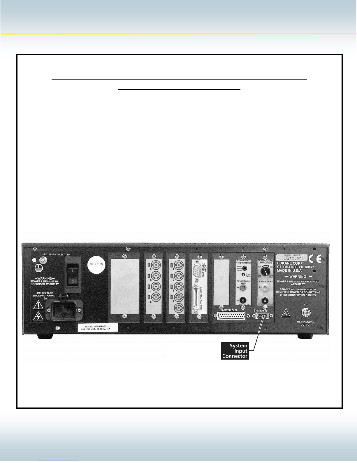
• The System In Connector Pin assignments
• The 200-1203 Basic Interface Cable
• System Input Signal Descriptions
• System Input Interface Examples
AN200
Rev 01
2900 Dukane Drive Saint Charles, IL 60174 USA
© Dukane Corporation 2003. All rights reserved.
Dukane Corporation
Phone (630) 797-4900 FAX (630) 797-4949
http://www.dukane.com/us
11101
1
Page 2
- 2 -
D
K
A
E
y
U
N
Apppplliiccaattiioonn
A
Noottee
N
Intelligent Assembly Solutions
1
The System In interface connector is one of the primary communications links between the DPC II / II+ input port and
the user automation equipment. This connector provides the automation with dedicated communication lines that
allow the automation to control the beginning and the end of a welding sequence.
Pin Number DPC Signal Name DPC Signal Type
1 Power Suppl
2 Ground 22VDC Return
3 Isolated Operate Input Input
4 Isolated Input Common
5 Isolated Press Control
6 Not Used Not Used
7 Ground +22VDC Return
8 Non Isolated Operate Input
9 Isolated Automation Stop /
Automation End of Weld 3
10 Not Used Not Used
11 Hand Probe Press Inhibit Input
12 MPC Probe/Setup Bit 0
13 MPC Probe/Setup Bit 1
14 MPC Probe/Setup Bit 2
15 Front Panel Control Lock Input
System Input Connector
1
2
4
4
4
+22 VDC (250 mA max)
Common for pin 3, 5, 9
Input
Input
Input
Input
Input
AN200
Rev 01
Notes:
1. SH707 on the 110-3606 system I/O PCB must be configured to the JU728 position when this
common is used.
2. This input requires the optional 110-3938 press control module. Configuration of the SH901
Jumper on the 110-3938 press control module may also be required.
3. This input is configured for use as Automation End of Weld at the factory. Jumper SH704 must
be reconfigured on the 110-3606 System I/O board to permit use of the Isolated Automation
Stop feature.
4. The MPC probe bit functionality requires the optional MPC feature. The Setup bit functionality
is available on all DPC II+ systems. Please refer to the DPC manual for further details on this
feature.
2900 Dukane Drive Saint Charles, IL 60174 USA
© Dukane Corporation 2003. All rights reserved.
Dukane Corporation
Phone (630) 797-4900 FAX (630) 797-4949
http://www.dukane.com/us
22102
2
Page 3
- 3 -
D
K
A
E
U
N
Apppplliiccaattiioonn
A
Noottee
N
Intelligent Assembly Solutions
AN200
Rev 01
Pin # Conductor Color
1 Red
2 Black
3 Blue / Black
4 Green / White
5 Blue / White
6 Red / Black
7 White / Black
8 White
9 Orange
10 Blue
11 Orange / Black
12 Red / White
13 Green / Black
14 Black / White
15 Green
Part Number Length
200-1203 10 FT
200-1203-15 15 FT
200-1203-20 20 FT
200-1203-25 25 FT
200-1203-30 30 FT
2900 Dukane Drive Saint Charles, IL 60174 USA
© Dukane Corporation 2003. All rights reserved.
Dukane Corporation
Phone (630) 797-4900 FAX (630) 797-4949
http://www.dukane.com/us
33103
3
Page 4

- 4 -
D
K
A
E
U
N
Apppplliiccaattiioonn
A
Noottee
N
Intelligent Assembly Solutions
System Input Signal Descriptions:
Isolated Operate Input - ( Pin 3 ) This system input signal receives the cycle initiation signal from automation. The
minimum duration for the activation of this input is 50 mS. The maximum duration of this input is
determined by the duration of the weld cycle. This input should be deactivated before the end of
the weld cycle to avoid an error condition. This system input can be reconfigured to
accommodate sourced (PNP) and sinking (NPN) signals as described in the SH707 configuration
section of this document. Please refer to the DPC manual for details on the activation and use of
the Operate (cycle initiate) feature.
Note: Reconfiguring the jumper of the SH901 jumper block on the 110-3938 press PCB will
configure the system to activate both the press and the ultrasound simultaneously at the top of
stroke position of the press.
Isolated Press Control Input - ( Pin 5 ) This system input receives a signal from automation that activates the Dukane
pneumatic press to the down position. The press will remain in the down position until this system
input is deactivated. This system input can be reconfigured to accommodate sourced (PNP) and
sinking (NPN) signals as described in the SH707 configuration section of this document. SH901
of the 110-3938 press board must also be reconfigured to the “Auto Control” position to activate
this system input. Please refer to the DPC manual for details on the activation and use of the
Press Control feature.
Operate Input - ( Pin 8 ) This system input signal receives the cycle initiation signal from automation. The
minimum duration for the activation of this input is 50 mS. The maximum duration of this input is
determined by the duration of the weld cycle. This input should be deactivated before the end of
the weld cycle to avoid an error condition. The system input can only accommodate a nonisolated sinking (NPN) signal for activation.
Note: Reconfiguring the jumper of the SH901 jumper block on the 110-3938 press PCB will
configure the system to activate both the press and the ultrasound simultaneously at the top of
stroke position of the press.
Isolated Automation Stop/End of Weld - ( Pin 9 ) This system input receives a signal from automation that will stop the
processing of portions of the welding cycle. The default functionality for this input is to end the
weld portion of the DPC cycle when the system input is activated. This input can be reconfigured
to Automation Stop which will stop the processing of all portions of the DPC cycle. Configuration
of this feature is described in the SH704 jumper configuration section of this document.
Hand Probe Press Inhibit - ( Pin 11 ) This system input receives a signal from a Dukane hand probe that disables all
press functionality.
MPC Probe / Setup Bit 1, 2, and 3 - ( Pins 12, 13, 14 ) These system inputs receive a Binary code from automation that
(MPC Feature Optional)
Front Panel Control Lock - ( Pin 15 ) This system input receives a signal from automation that disables the DPC test
is used to select a DPC setup and a DPC probe to be used for the next welding cycle. Please
refer to the DPC manual or application AN203 for details on the activation and use of the MPC or
Remote Setup Select (DPCII+ only) features.
switch as well as the key pad for the DPC controller (DPC II+ only).
AN200
Rev 01
2900 Dukane Drive Saint Charles, IL 60174 USA
© Dukane Corporation 2003. All rights reserved.
Dukane Corporation
Phone (630) 797-4900 FAX (630) 797-4949
http://www.dukane.com/us
44104
4
Page 5

- 5 -
D
K
A
E
U
N
Apppplliiccaattiioonn
A
Noottee
N
Intelligent Assembly Solutions
Internal DPC Jumper Block Configuration Options
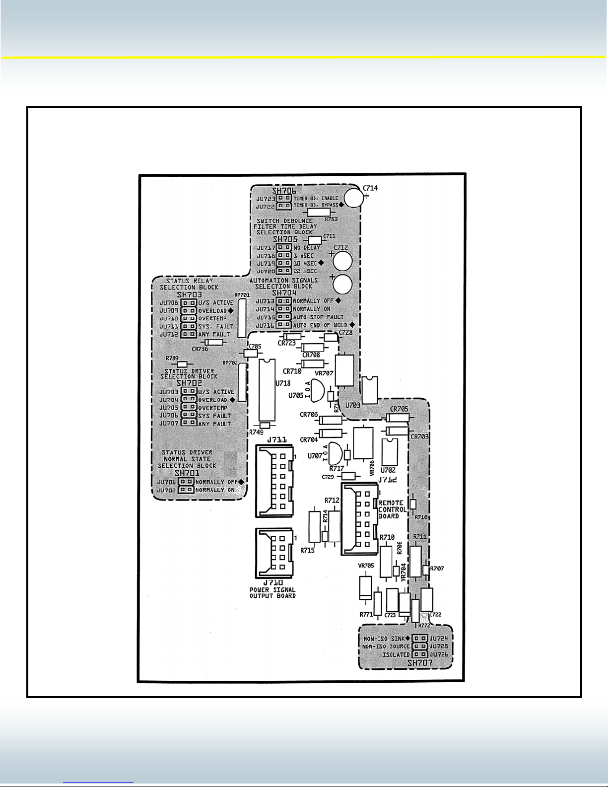
The DPC II / II+ provides four internal jumpers that allow the user to configure the system inputs for compatibility with the
users equipment. Three of the configurable jumpers are located on the DPC II / II+ 110-3606 system interfa ce bo ard
which is located in bottom of the DPC near the rear panel. The 110-3606 system interface board can be identified as the
board connected to the System Input and System Output connectors which extend from the back panel of the DPC II / II+
chassis. The fourth configurable jumper is located on the 110-3937 press control board. The pre ss control board can be
identified as the board connected to the press control cable which is conne cted to the DPC press.
Warning: The DPC chassis cover should not be removed until the DPC power cord has been removed from the AC
voltage supply. After removing the DPC power cord from the AC voltage supply, the DPC requires fifteen minutes to
discharge to safe levels. Do not remove the DPC cover until the DPC has discharged to safe levels. Avoid contact with
all internal DPC components that are not specified within the jumper configuration procedure below. Failure to com ply
with these requirements can result in serious personal injury and damage to the DPC welding system.
Automation Cycle Stop / End of Weld Configuration
(Associated with pin 9)
Jumper Block – SH704
JU713 – Normally OFF (Factory Default )
JU714 – Normally ON
JU715 – Automation Stop Fault
JU716 – Automation End of Weld (Factory Default)
Note: There will be two jumpers instaled in SH704.
Switch Debounce Filter Delay for System Inputs
(Associated with pins 3 and 8)
Jumper Block – SH705
JU717 – No Time Delay (used for solid state switches)
JU718 – 1 msec
JU719 – 10 msec (Factory Default)
JU720 – 22 msec
System Input Signal Type Configuration
(Associated with pins 3, 5, and 9)
Jumper Block – SH707
JU724 – Non Isolated Sink (Factory Default) Dry contact between input and DPC ground.
JU725 – Non Isolated Source Dry contact between input and +22VDC.
JU726 – Isolated Source Input can be either sinking (NPN) or sourcing (PNP). A signal of
5 to 24 VDC is required at the isolated input pin. The current is
internally limited to 12.5mA.
AN200
Rev 01
2900 Dukane Drive Saint Charles, IL 60174 USA
© Dukane Corporation 2003. All rights reserved.
Dukane Corporation
Phone (630) 797-4900 FAX (630) 797-4949
http://www.dukane.com/us
55105
5
Page 6
- 6 -
D
K
A
E
U
N
Apppplliiccaattiioonn
A
Noottee
N
Intelligent Assembly Solutions
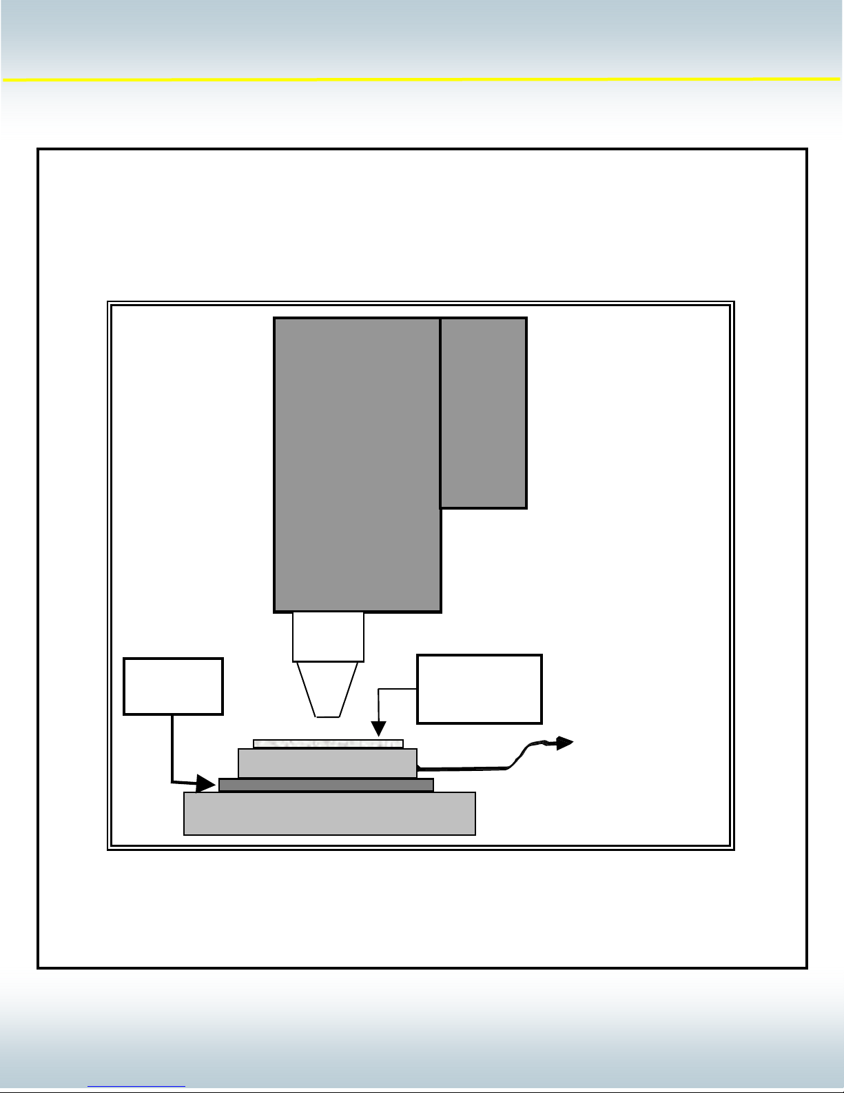
System Input Example for the Ground Detect feature:
Note: Sh704 must be configured properly to activate the ground detect feature.
AN200
Rev 01
2900 Dukane Drive Saint Charles, IL 60174 USA
© Dukane Corporation 2003. All rights reserved.
Dukane Corporation
Phone (630) 797-4900 FAX (630) 797-4949
http://www.dukane.com/us
66106
6
Page 7
- 7 -
D
K
A
E
U
N
Apppplliiccaattiioonn
A
Noottee
N
Intelligent Assembly Solutions
System Input Interface Example for the DPC Ground Detect Feature:
Note: Internal circuit board jumper for jumper block SH704 must be reconfigured for proper operation of this feature.
AN200
Rev 01
Electrical
Insulator
Welding Table / Base
2900 Dukane Drive Saint Charles, IL 60174 USA
© Dukane Corporation 2003. All rights reserved.
Customer
Product
Fixture
200-1203 Cable
Dukane Corporation
Phone (630) 797-4900 FAX (630) 797-4949
http://www.dukane.com/us
Connect to
DPC II / II+
System Input pin 9
77107
7
Page 8
- 8 -
D
K
A
E
U
N
Apppplliiccaattiioonn
A
Noottee
N
Intelligent Assembly Solutions
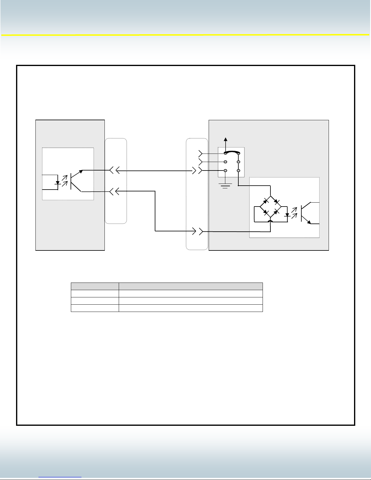
DPC II / II+ System Input Interface Example:
(DPC II / II+ configured to accommodate an NPN type PLC output card that sinks the DPC inputs).
+22 VDC
DPC II / II+
JU724 (Factory Default)
JU726
JU725
Bi-directional
Input Device
Output Device
200-1203 Cable
4
AN200
Rev 01
PLC
J701
PIN NUMBER PIN DESCRIPTION
3 ISOLATED OPERATE INPUT
5 ISOLATED PRESS CONTROL
9 ISOLATED AUTOMATION STOP/END OF WELD
Note: This diagram provides a simplified representation of the DPC II / II+ input device for the purpose
of demonstrating circuit functionality.
2900 Dukane Drive Saint Charles, IL 60174 USA
© Dukane Corporation 2003. All rights reserved.
Dukane Corporation
Phone (630) 797-4900 FAX (630) 797-4949
http://www.dukane.com/us
88108
8
Page 9
- 9 -
D
K
A
E
U
N
Apppplliiccaattiioonn
A
Noottee
N
Intelligent Assembly Solutions
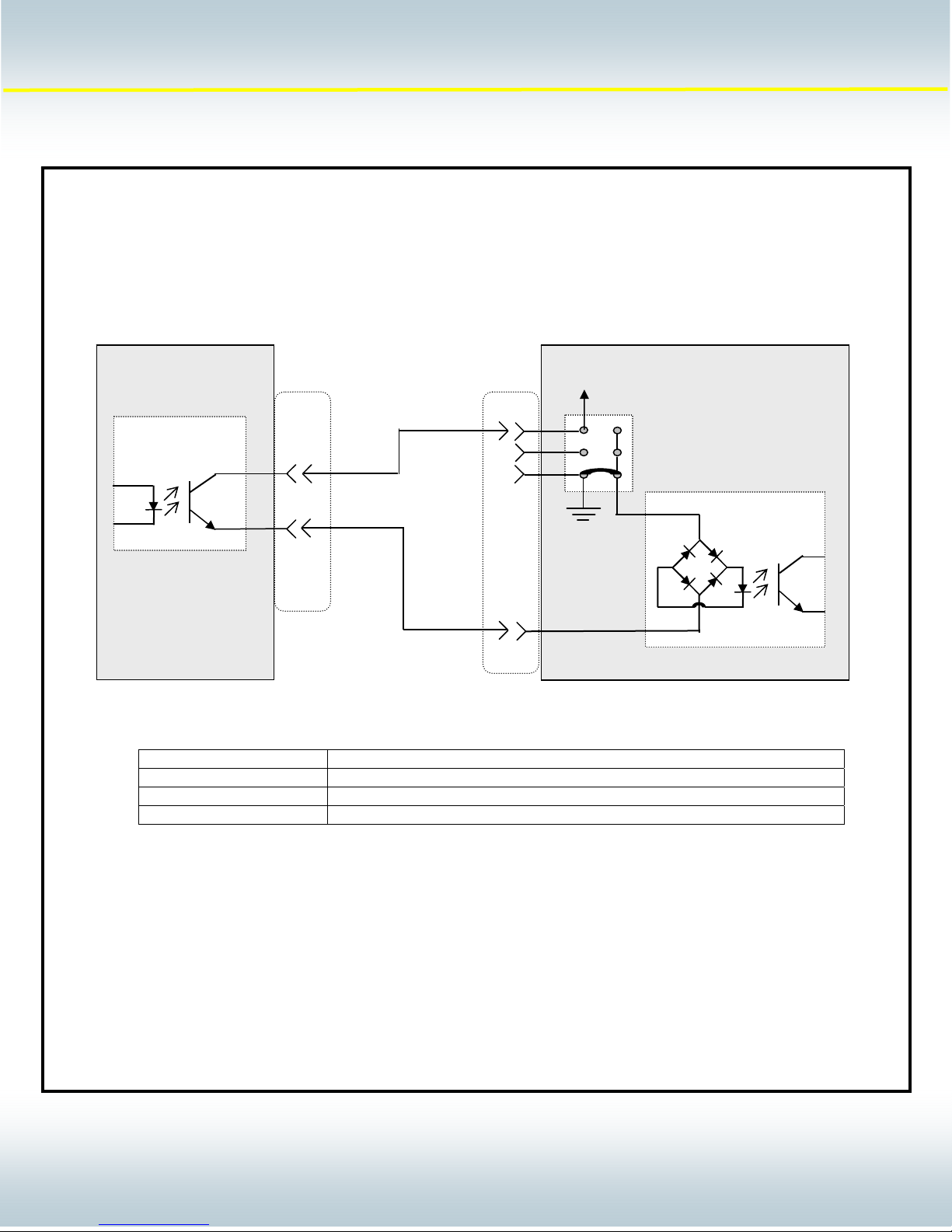
DPC II / II+ System Input Interface Example:
(DPC II / II+ configured to accommodate a PNP type PLC output card that utilizes the DPC power to source the DPC
inputs).
+22 VDC
DPC II / II+
Bi-directional
Input Device
Output Device
200-1203 Cable
JU724 (Factory Default)
4
JU726
JU725
AN200
Rev 01
PLC
See Chart Below for
Input Pin assignments
PIN NUMBER PIN DESCRIPTION
3 ISOLATED OPERATE INPUT
5 ISOLATED PRESS CONTROL
9 ISOLATED AUTOMATION STOP/END OF WELD
Note: This diagram provides a simplified representation of the DPC II / II+ input device for the purpose
of demonstrating circuit functionality.
J701
2900 Dukane Drive Saint Charles, IL 60174 USA
© Dukane Corporation 2003. All rights reserved.
Dukane Corporation
Phone (630) 797-4900 FAX (630) 797-4949
http://www.dukane.com/us
99109
9
Page 10
- 10 -
D
K
A
E
U
N
Apppplliiccaattiioonn
A
Noottee
N
Intelligent Assembly Solutions
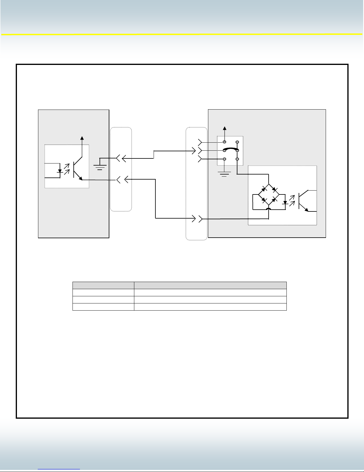
DPC II / II+ System Input Interface Example:
(DPC II / II+ configured to accommodate a PNP type PLC output card requiring isolation)
+22 VDC
+24 VDC
JU724 (Factory Default)
JU726
JU725
Output Device
PLC
200-1203 Cable
4
2
AN200
Rev 01
DPC II / II+
Bi-directional
Input Device
See Chart Below for
Input Pin assignments
System Input Connector
*PIN NUMBER PIN DESCRIPTION
3 ISOLATED OPERATE INPUT
5 ISOLATED PRESS CONTROL
9 ISOLATED AUTOMATION STOP/END OF WELD
Note: This diagram provides a simplified representation of the DPC II / II+ input device for the purpose
of demonstrating circuit functionality.
2900 Dukane Drive Saint Charles, IL 60174 USA
© Dukane Corporation 2003. All rights reserved.
Dukane Corporation
Phone (630) 797-4900 FAX (630) 797-4949
http://www.dukane.com/us
10101010
10
 Loading...