

Page 1
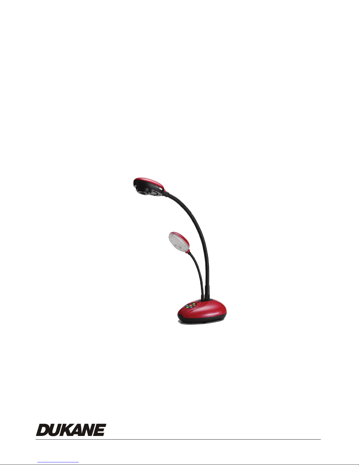
Camera 335
Document Camera
User’s Guide
#401-335-00
Page 2

Table of Contents
CHAPTER 1 PRECAUTIONS ................................................................................ 2
z Safety Precautions ...................................................................................3
z FCC Warning............................................................................................ 3
z EN55022 (CE Radiation) Warning............................................................ 3
CHAPTER 2 PACKAGE CONTENT ...................................................................... 4
CHAPTER 3 PRODUCT OVERVIEW .................................................................... 5
3.1 P
3.2 I/O
3.3 DIP
R
RODUCT INTRODUCTION............................................................................ 5
CONNECTION ........................................................................................6
SWITCH SETTING ................................................................................. 6
EMOTE CONTROL ............................................................................................ 7
CHAPTER 4 HOW TO USE IT ............................................................................... 8
4.1 G
4.1.1 T
4.1.2 A
4.2 M
4.2.1 S
4.2.2 『P
4.2.3 Z
ETTING STARTED...................................................................................... 8
URN ON THE DOCUMENT CAMERA .......................................................... 8
UTOMATIC IMAGE ADJUSTMENT ............................................................. 8
AJOR FUNCTIONS..................................................................................... 9
ELECT INPUT SOURCE ...........................................................................9
HOTO/TEXT』MODES ........................................................................ 9
OOM IN / OUT....................................................................................... 10
A
UTO FOCUS ................................................................................................... 10
B
RIGHTNESS ADJUSTMENT .............................................................................. 10
4.2.6 D
ENU NAVIGATION AND SELECTION ................................................................... 11
M
4.3 A
4.3.1 C
4.3.2 P
ISPLAY THE COMPLETE CONTROL MENU (OSD) ON SCREEN DISPLAY.... 11
DVANCED FUNCTIONS .............................................................................12
APTURE OF IMAGES ............................................................................12
LAY BACK CAPTURED IMAGES.............................................................. 12
0
Page 3

4.3.3 DELETE CAPTURED IMAGES .................................................................. 12
4.3.4 P
4.3.5 A
RESET CONTROLS ............................................................................... 13
UTO ERASE ........................................................................................ 13
CHAPTER 5 CONTROL MENU (OSD MENU) INTRODUCTION (ON SCREEN
DISPLAY).............................................................................................................. 15
5.1 O
5.2 C
PERATION .............................................................................................. 15
ONTROL MENU (OSD MENU) .................................................................. 15
CHAPTER 6 USER SOFTWARE INSTRUCTIONS - USB335 ............................18
6.1 I
6.2 F
NSTALLATION........................................................................................... 18
UNCTIONS (USB335 SOFTWARE)...........................................................22
Top window tool bar Functions ...................................................................... 24
6.2.1
FILE ( FOLDER ICON) ............................................................................ 24
INITIAL WINDOW (BEFORE CAMERA IMAGE IS PRESENT) ............................... 24
REAL TIME (LIVE CAMERA IMAGE) ................................................................. 25
6.2.3
EDIT MODE............................................................................................ 25
6.2.4
FREEZE ................................................................................................ 25
6.2.5
CAPTURE.............................................................................................. 25
6.2.6
PAINT TOOL ( ANNOTATION)................................................................ 26
6.2.7
FULL SCREEN .......................................................................................26
6.2.8
IMAGE ADJUST (FOR THE LIVE IMAGE) ................................................... 26
6.2.9 I
6.3 O
6.3.1 D
6.3.2 E
MAGE PREVIEW VIEW TOOL BAR ........................................................... 27
PERATION INFORMATION......................................................................... 29
ISPLAY IMAGE: .................................................................................29
DIT IMAGE: ANNOTATION ................................................................... 30
6.3.3 USB335
SOFTWARE MENUS................................................................. 30
CHAPTER 7 TROUBLESHOOTING.................................................................... 32
1
Page 4

Chapter 1 Precautions
Always follow these safety instructions when setting up and using the Document Camera:
1. Please do not tilt the machine while using.
2. Do not place the Document Camera on an unstable trolley, stand or table.
3. Do not use the Document Camera near water or source of heat.
4. Use attachments only as recommended.
5. Use the type of power source indicated on the Document Camera. If you are not sure
of the type of power available, consult your dealer or local electricity company for
advice.
6. Place the Document Camera where it can be easily unplugged.
7. Always take the following precautions when handling the plug. Failure to do so may
result in sparks or fire.
Ensure the plug is free of dust before inserting it into a socket.
Ensure that the plug is inserted into the socket securely.
8. Do not overload wall sockets, extensions leads or multi-way plug boards as this may
cause fire or electric shock.
9. Do not place the Document Camera where the cord can be stepped on as this may
result in fraying or damage to the lead or the plug.
10. Unplug the projector form the wall socket before cleaning. Use a damp cloth for
cleaning. Do not use liquid or aerosol cleaners.
11. Do not block the slots and openings in the case. They provide ventilation and prevent
the Document Camera from overheating. Do not place the Document Camera on a
sofa, rug or other soft surface or in a built-in installation unless proper ventilation is
provided.
12. Never push objects of any kind through cabinet slots. Never allow liquid of any kind to
spill into the Document Camera.
13. Except as specifically instructed in this User’s Manual, do not attempt to operate this
product by yourself. Opening or removing covers may expose you to dangerous
voltages and other hazards. Refer all servicing to licensed service personnel.
14. Unplug the Document Camera during thunderstorms or if it is not going to be used for
an extended period, do not place the Document Camera or remote control on top of
beat-emitting equipment or heated objects such as a car and etc.
15. In the following situations, unplug the Document Camera from the wall outlet and
refer servicing to licensed service personnel:
If the power cable or plug becomes damaged or frayed.
2
Page 5
If liquid is spilled into it or the Document Camera has been exposed to rain or
water.
z Safety Precautions
Warning: To reduce the risk of fire or electric shock, do not expose this
appliance to rain or moisture.
This Document Camera has a 2 wire AC line Plug. This is a safety feature to ensure that the
plug will fit into the power outlet. Do not try to defeat this safety feature.
If the Document Camera will not be used for an extended time, unplug it from the power
outlet.
CAUTION
RISK OF ELECTRIC SHOCK
Caution: To reduce the risk of electric shock. Do not remove the cover (or back). No
user-serviceable parts inside. Refer servicing to licensed service Personnel.
This symbol indicates that
dangerous voltage
constituting a risk of electric
shock is present within this
unit.
This symbol indicates that
there are important operating
and maintenance instructions
in this User’s Manual with this
unit.
z FCC Warning
This Document Camera has been certified to comply with the limits for a Class A computing
device, pursuant to Subpart J of Part 15 of FCC Rules. These limits are designed to provide
reasonable protection against a harmful interference when the equipment is operated in a
commercial environment.
z EN55022 (CE Radiation) Warning
This product is intended for use in a commercial, industrial, or educational environment. It is
not intended for residential use.
This is a Class A product. In a domestic environment it may cause radio interference, in
which case the user may be required to take adequate measures. The typical use is in a
conference room, meeting room or auditorium.
3
Page 6
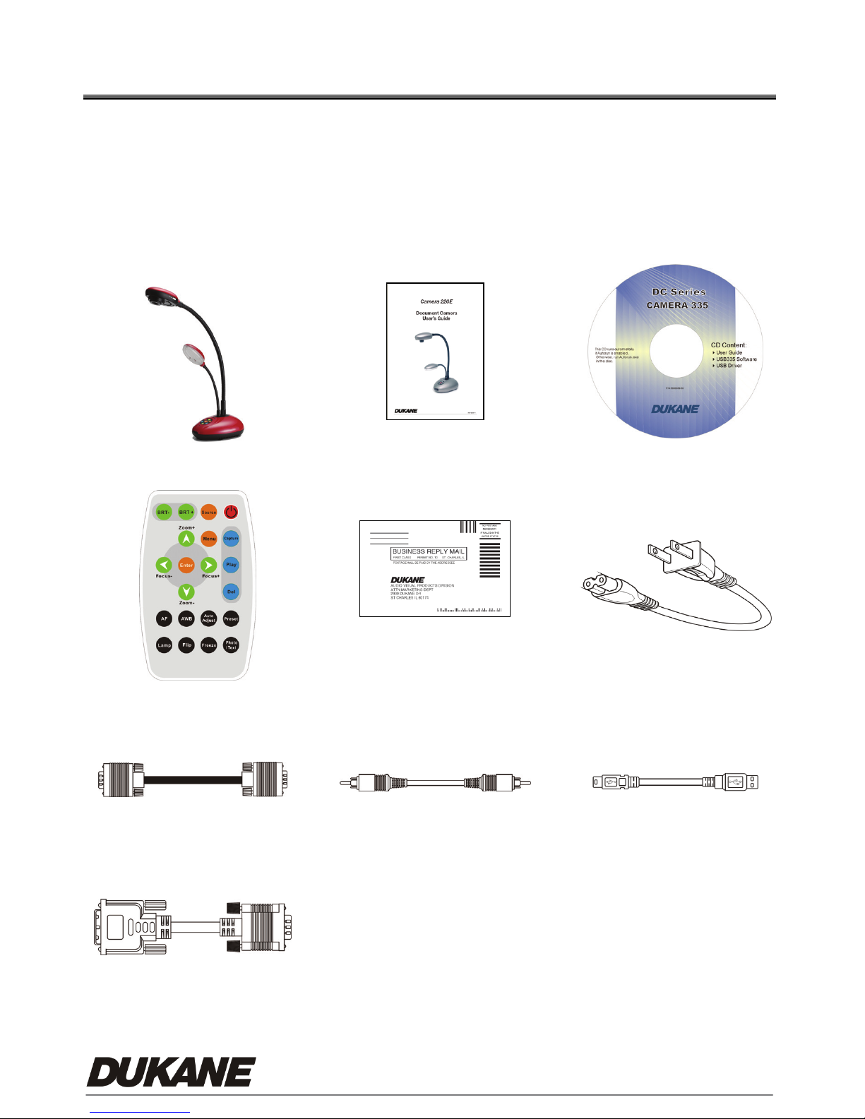
Chapter 2 Package Content
Please make sure the package comes with the following items when you unpack:
(Total 9 items):
Main Unit
Remote
User’s Guide CD
Warranty Card Power Cable
VGA Cable C-Video Cable USB Cable
DVI Adapter (Optional)
4
Page 7
Chapter 3 Product Overview
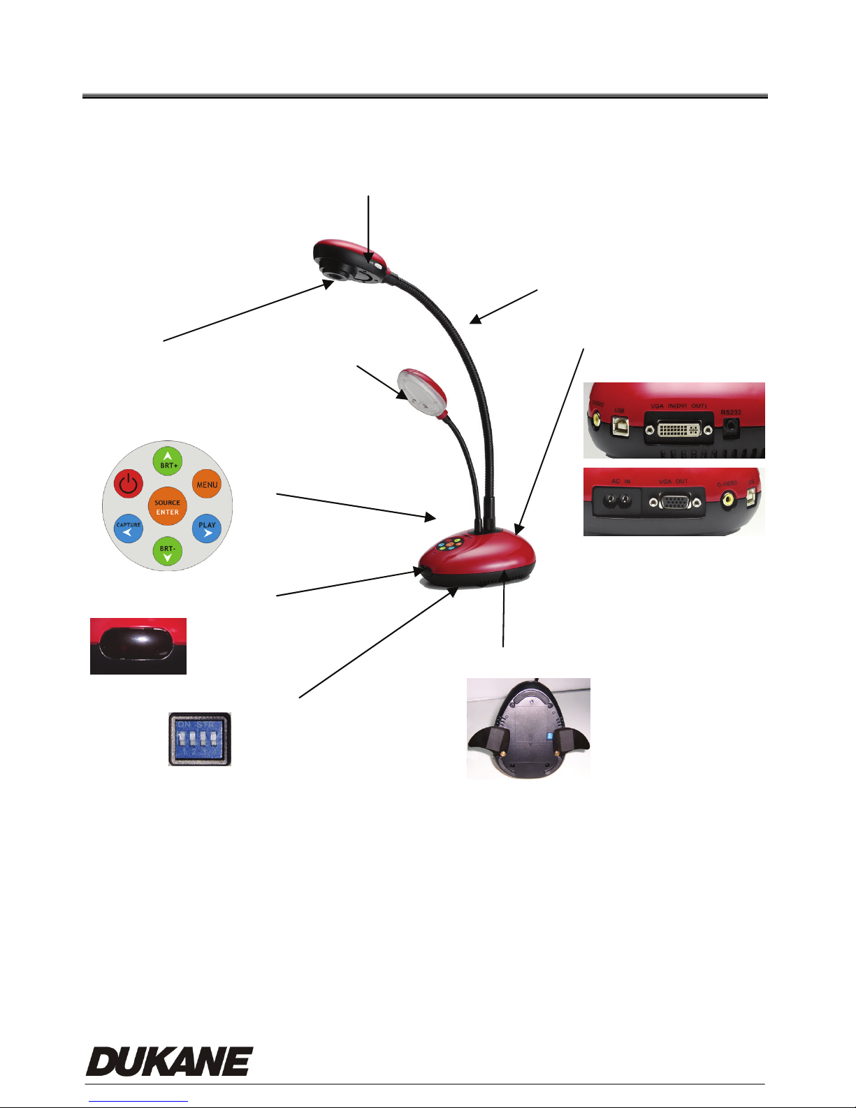
3.1 Product Introduction
2. Lens
6. Power/Control keypad
4. Lamp
1. Auto Focus Button
3. Gooseneck
5. I/O Connection
7. Infrared receiver area
8. DIP Switch
9. Auxiliary Stand
5
Page 8
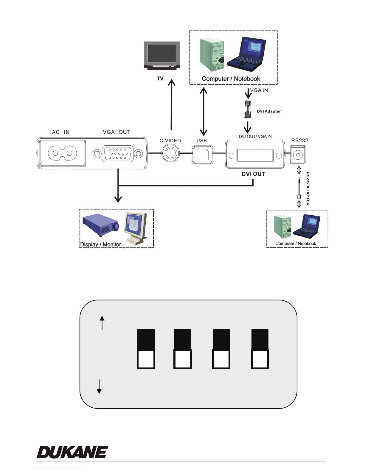
3.2 I/O Connection
3.3 DIP Switch Setting
Factory default settings are as the following:
ved
ON
OFF
PAL C-Video SVGA Reserved
NTSC RGB XGA Reserved
1234
(Reserved is OFF all the time)
6
Page 9
3
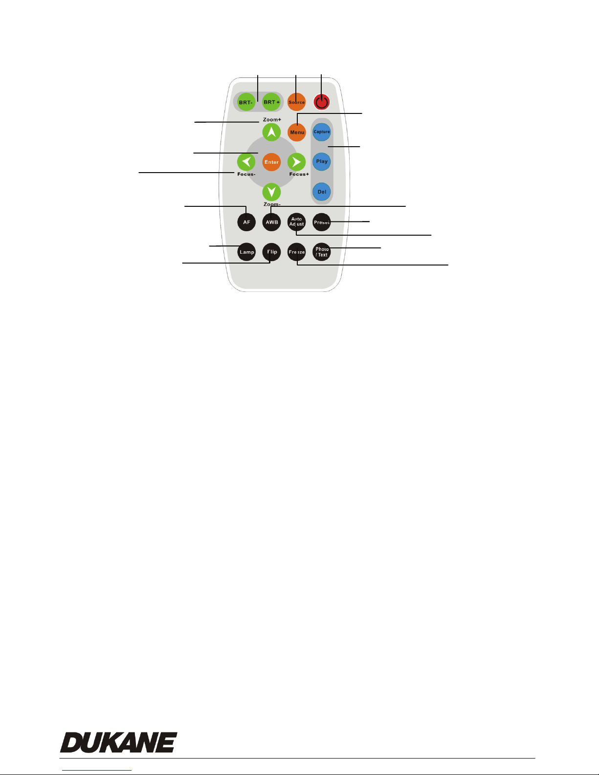
3.4 Remote Control
1
8
7
6
9
4
5
11
15
10
12
* Only use CR2025 as replacement battery. Please properly dispose of any used
1. Power:
Power on or off.
2. Source:
Switch between different signal
sources.
3. BRT+/-:
Make the image brighter or darker
4. Menu:
Show the Control Menu (OSD, On
Screen Display, Menu)
5. Capture:
Capture the image
Play/Del:
Recall/Delete the saved images in the
flash memory of your Document
Camera.
6. ghij / Enter:
g h i j: Select
Enter: Enable the selected function
function
batteries.
8. Focus +/- :
9. AF:
10. Lamp:
11. AWB:
12. Flip:
13. Auto Adjust:
14. Freeze:
15. Preset:
16. Photo/ Text:
16
Manual Focus for fine adjustment
Auto Focus
Turn on/ off Lamp
Auto white balance.
Rotate the image by 180 degrees
Auto-adjust for the optimum image
Freeze the image
Save/load your setting parameters
(like brightness, lamp and focus)
Select the text or photo mode
13
14
7. Zoom +/-:
Make the image larger & smaller
7
Page 10
Chapter 4 How to use it
4.1 Getting Started
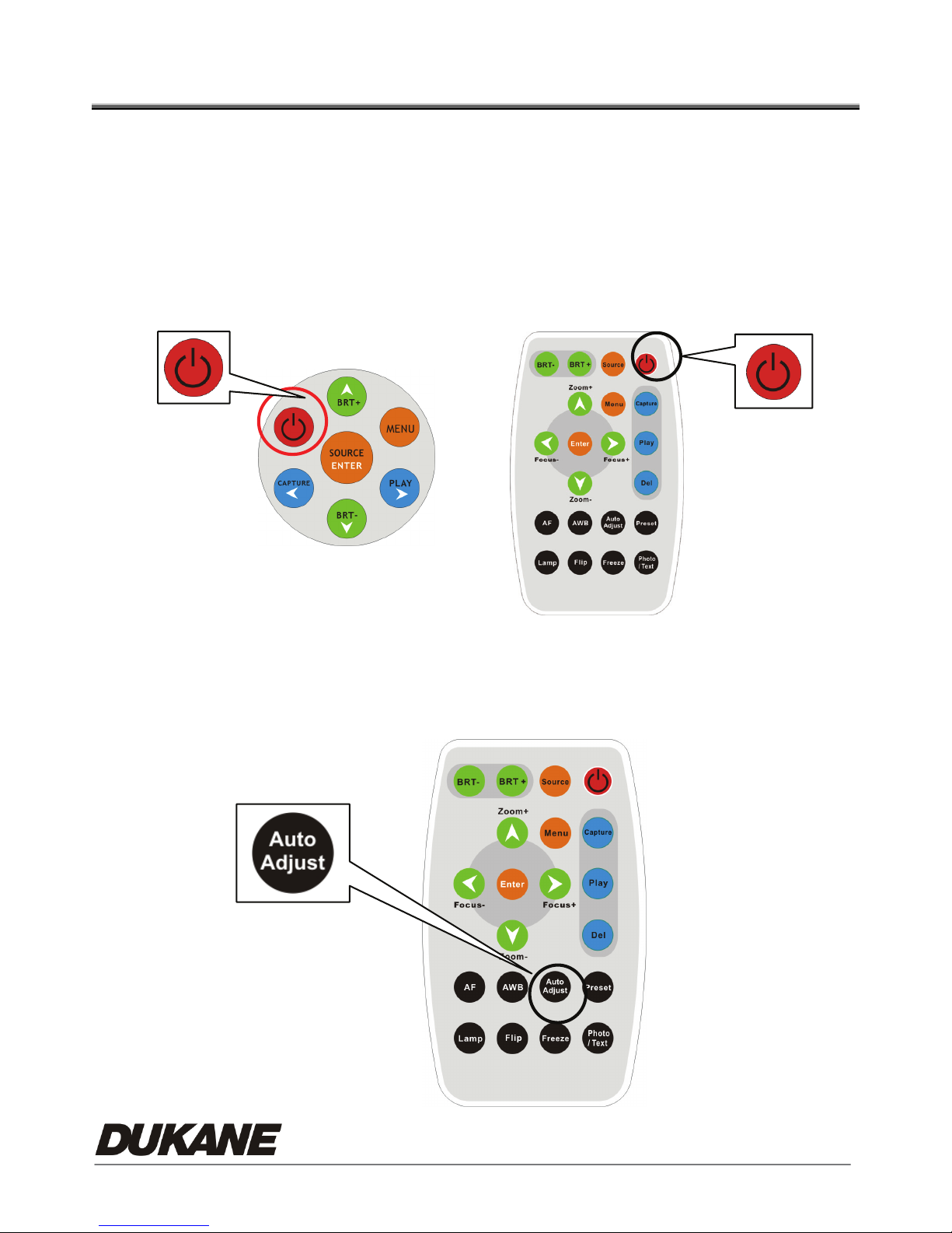
4.1.1 Turn on the Document Camera
When the power cord is plugged in, the LED indicator will be "Red".
When turned on, the LED indicator will be "Blue".
4.1.2
Remote
Keypad
Automatic Image Adjustment
Auto-adjust to obtain the optimum image. It may require a few seconds
for this process.
8
Page 11
4.2 Major Functions
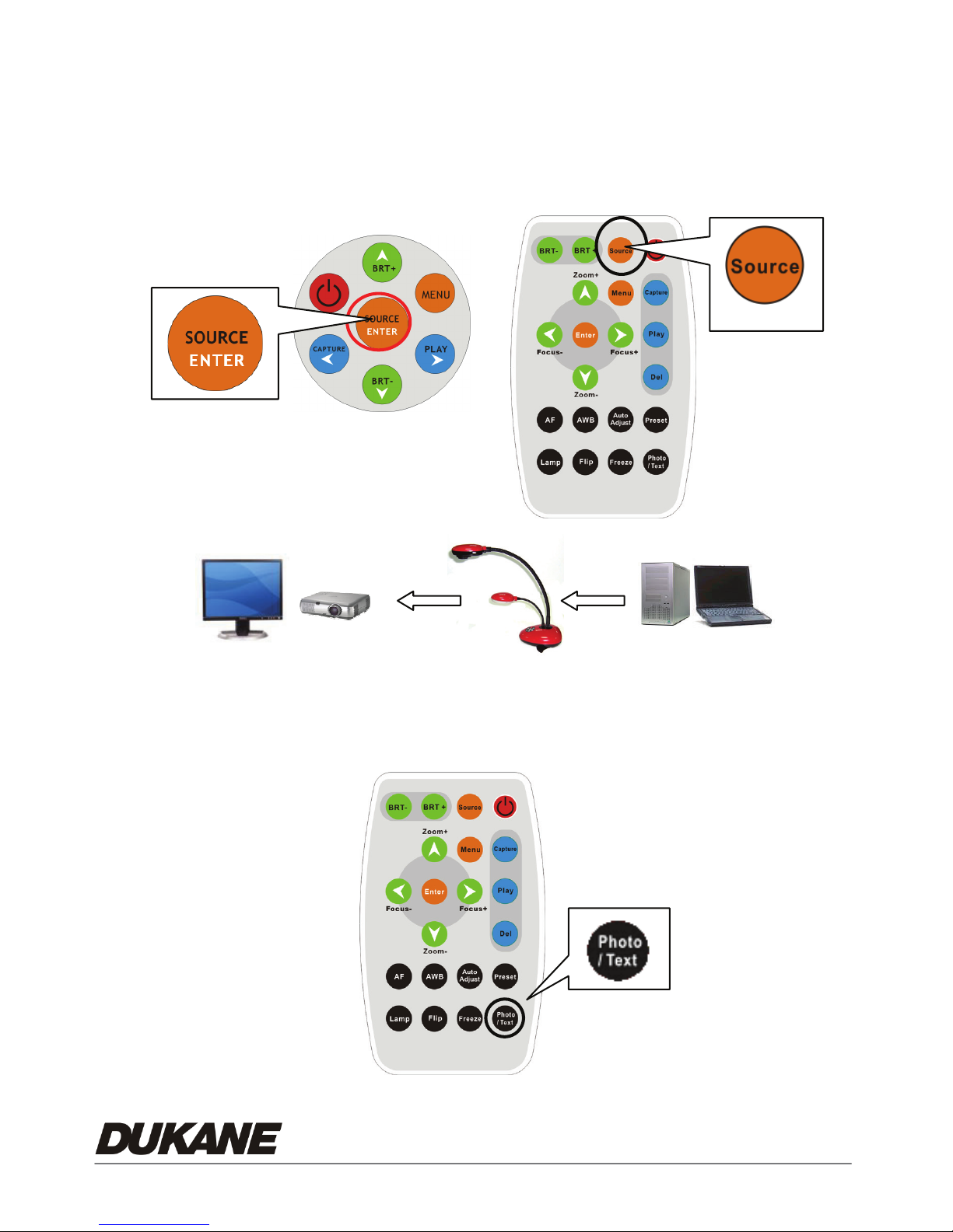
4.2.1 Select Input Source
The default input source is set as the "Document Camera", press 『Source』to switch.
Keypad
Remote
Monitor
4.2.2 『Photo/Text』Modes
The default setting is "Photo". Users can switch mode by pressing "Photo/Text" button.
Remote
9
Page 12
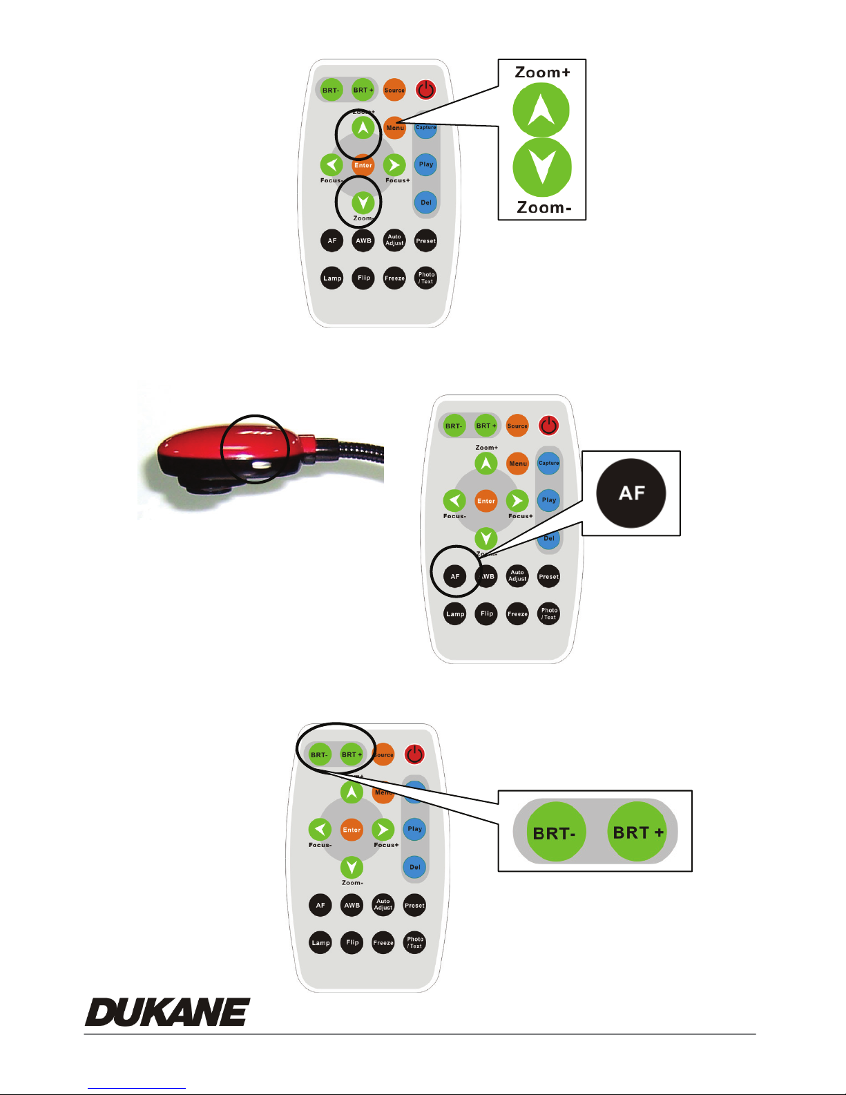
4.2.3 Zoom in / out
4.2.4 Auto Focus
Goose-head
Remote
4.2.5 Brightness Adjustment
10
Page 13
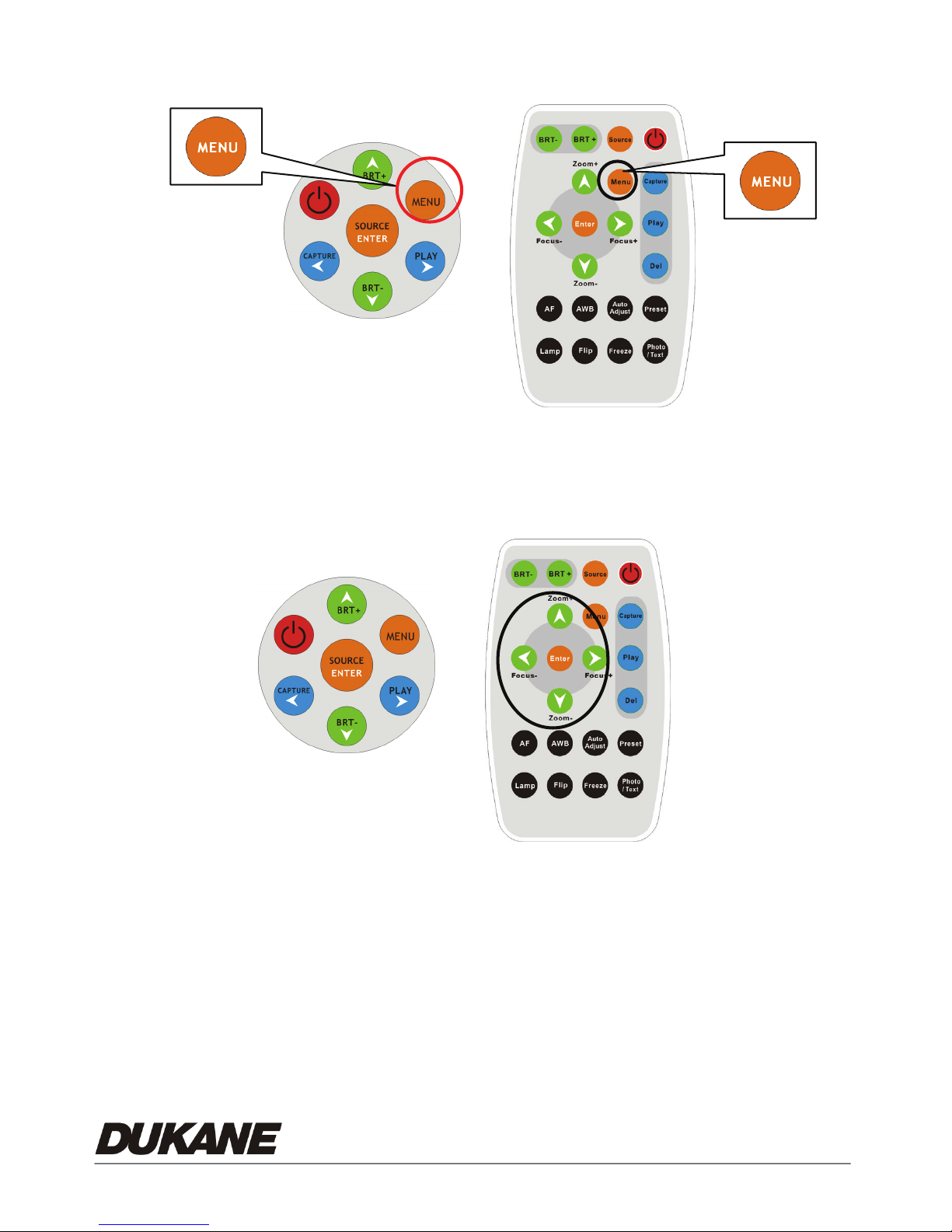
4.2.6 Display the complete control menu (OSD) On Screen Display
Keypad
4.2.7 Menu navigation and selection
Keypad
Remote
Remote
1. Press『^ v< >』navigate menu.
2. Press『Enter』to select.
11
Page 14

4.3 Advanced Functions
4.3.1 Capture of Images
Remote or Keypad::Press『Capture』button from remote control.
4.3.2 Play back captured Images
Remote or Keypad:
1. Press『Play』to show thumbnail images in memory.
2. Use『ef』to select thumbnail.
3. Press『Enter』to display as full screen.
4. Use『ef』to view next image.
5. Press『Play』to go back to thumbnail images.
6. Press『Menu』to Exit.
4.3.3 Delete Captured Images
Remote:
1. Press『Play』 to show all thumbnail images in memory.
2. Use『ef』to select.
3. Press『Del』to delete.
4. Press『Menu』to Exit
Keypad:
1. Press『Play』 to show all thumbnail images in memory.
2. Use『ef』select one.
3. Press『Enter』to display a full screen image.
4. Press『Menu』to invoke the on screen Control Menu (OSD Menu).
5. Use『ef』to select
6. Use『d S』to select『Delete』or 『Delete All』
12
(Storage).
Page 15

7. Press『Enter』to execute.
8. Press 『Menu』to Exit
4.3.4 Preset controls
Preset save: Save the customized user setting parameters (Ex. Zoom,
brightness, color, AE setting).
1. Press『Preset』to entry the Preset menu.
2. Use『d』to『save』
3. Use『f』to『Yes 』
4. Press『Enter』to execute.
Preset Load:Invoke the customized user setting parameters (Ex. Zoom,
brightness, color, AE setting).
1. Press『Preset』to entry the Preset menu.
2. Use『d』to『Load』
3. Use『f』to 『Yes』
4. Press『Enter』to execute.
【NOTICE】You can store up to four presets in each of five image modes 1.
Normal 2.Gray 3.Slide 4.Microscope 5.Film.
4.3.5 Auto Erase
With Auto Erase function turned on, all captured images will be erased
automatically once the Document Camera is turned off.
1. Press『Menu』to invoke the full Control Menu (OSD Menu).
2. Use『f』to
(Storage).
3. Use『S』to select『Auto Erase』.
4. Use『f』to『On』.
13
Page 16

5. Use『d』to『Yes 』.
6. Press『Enter』to execute.
14
Page 17
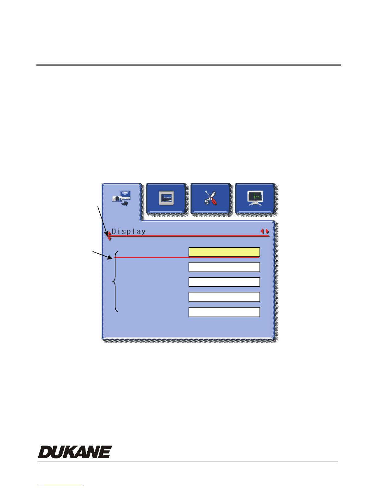
Chapter 5 Control Menu (OSD Menu)
Introduction (On Screen Display)
5.1 Operation
A. Use『fe』to select main function.
B. Use『dS』to select sub-item.
C. The activated item with red line and yellow block. Use『d S』to select other
items.
D. 『fe』: For More functions, you can press『fe』to execute.
E. 『』:If Only one item is desired , you can press『Enter』to execute.
F. Press『Menu』to Exit.
A
C
B
Image
c
d
Freeze
Flip
Digital Zoom
Focus
5.2 Control Menu (OSD Menu)
z There are Display, Storage, Setting and Advanced function pages in the
Control Menu (OSD Menu).
D
fe
z The menu will be automatically turned off when not being used for a
while.
15
Page 18
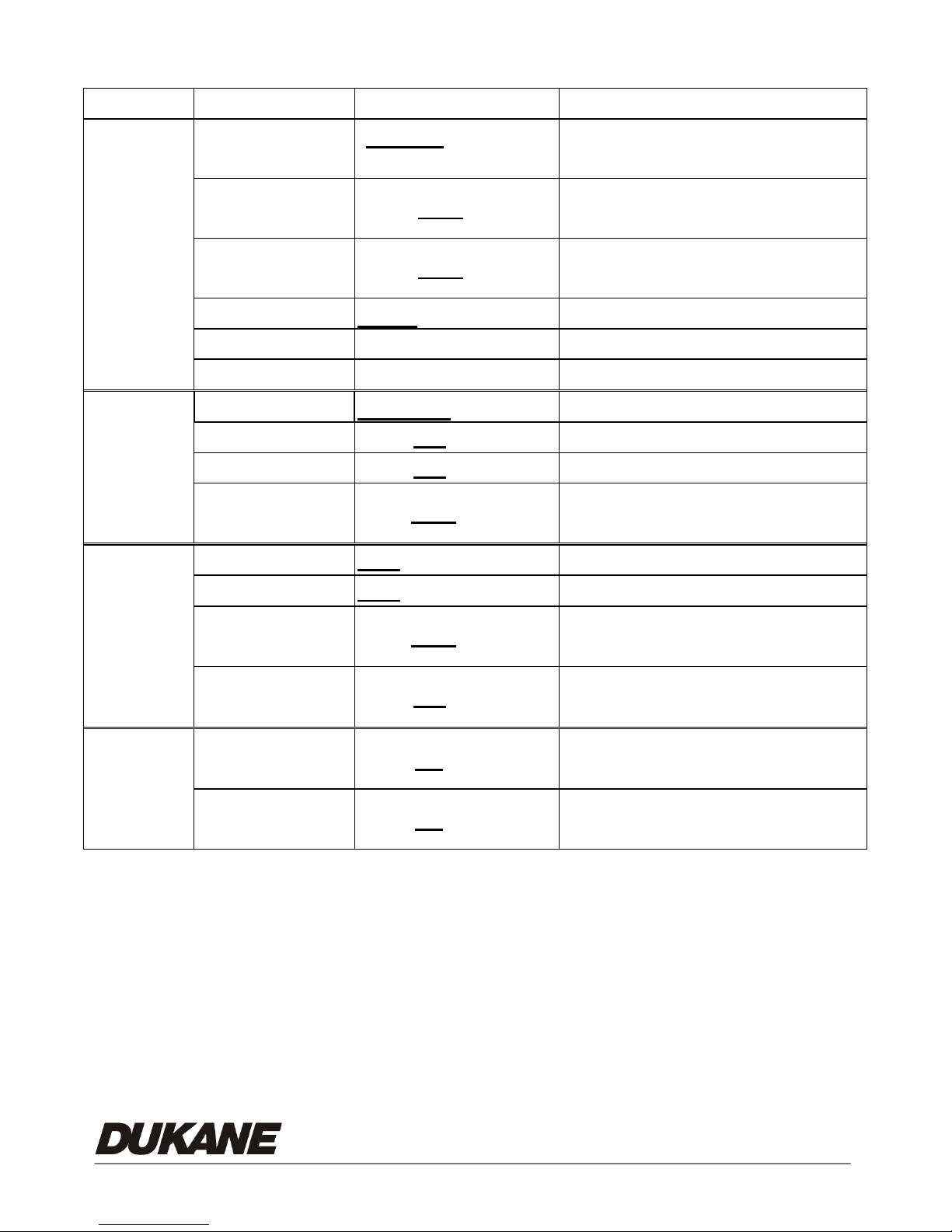
¾ VGA Mode (Computer Image output mode)
Layer 1
Display
Storage
Layer 2 Layer 3 Description
Normal/
Gray/Slide/
Select Normal/Gray/Slide/
Image
Freeze
Flip
Microscope/Film
ON /OFF
ON /OFF
Microscope/Film image mode
Use Freeze to retain the image on
the screen.
Flip image by 180°
(Up→Down & Left→Right )
Gamma
Digital Zoom
Focus
Delete
Delete All
Format
Auto Erase
Photo
100%~1600%
0~Max Adjust image focus
Execute
Yes/No
Yes/No
ON/OFF
/ Text Select Photo or Text mode
Adjust Zoom 100% ~ 1600%
Delete captured images
Delete all captured images
Format internal storage memory
Delete all captured images when
user turns off the power.
Setting
Advance
Lamp
AE
Night vision
Factory Reset
Preset Load
Preset Save
/OFF
ON
/OFF
ON
ON/OFF
Yes/No
Yes/No
Yes/No
Select Lamp On or Off.
Auto Exposure
Select Night view function On or
Off.
Restore unit back to factory
setting
Invoke the customized user
setting values
Save a set of customized user
setting values
16
Page 19
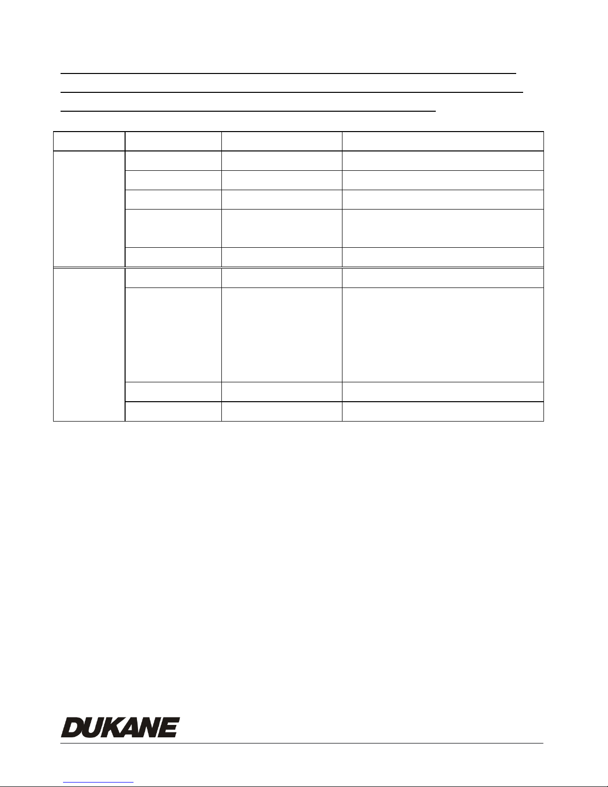
¾ C-Video Mode ( Composite Video output mode)
This is a low resolution output that requires the camera’s bottom
switch to be reset. THERE IS NO COMPOSITE VIDEO OUTPUT
WHEN THE “COMPUTER IMAGE” MODE IS USED.
Layer 1 Layer 2 Layer 3 Content
Display
Setting
Focus
Gamma
Image
Freeze
Exit
Lamp
Advance
Factory Reset Enter / Exit Select a fitting output format.
Exit
-/+
Photo/Te xt Select Photo/Tex t mod e
Normal/Gray Select Normal/Gray mode
OFF/ON
ON/OFF
Full Range
ON/OFF
Night vision
ON/OFF
Exit
100~300
Use Freeze to retain the image on the
screen.
Exit the Menu
Turn on/off lamp
Adjust On or Off of Full screen &
Night view function
17
Page 20
Chapter 6 User software instructions
- USB335
Using the Camera USB with a Computer
6.1 Installation
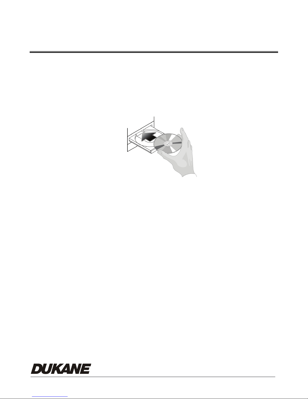
1. Insert the software CD in your computer’s CD-ROM.
2. Connect the Camera and PC with USB Cable. Follow instructions for
driver download.
3. Before you install USB335, please be sure your system meets these
requirements.
z Operation System:Windows XP SP2, Windows 2000 SP4,
z CPU:Intel Pentium 4 2.0 G over and above
z 256MB RAM
z Minimum 40MB HD space
z CD ROM、DVD ROM。(installation use)
z Display : 1024x768 above
z Microsoft Office Power Point
4. The “Auto run” program will be shown automatically, if you would like to
18
Page 21
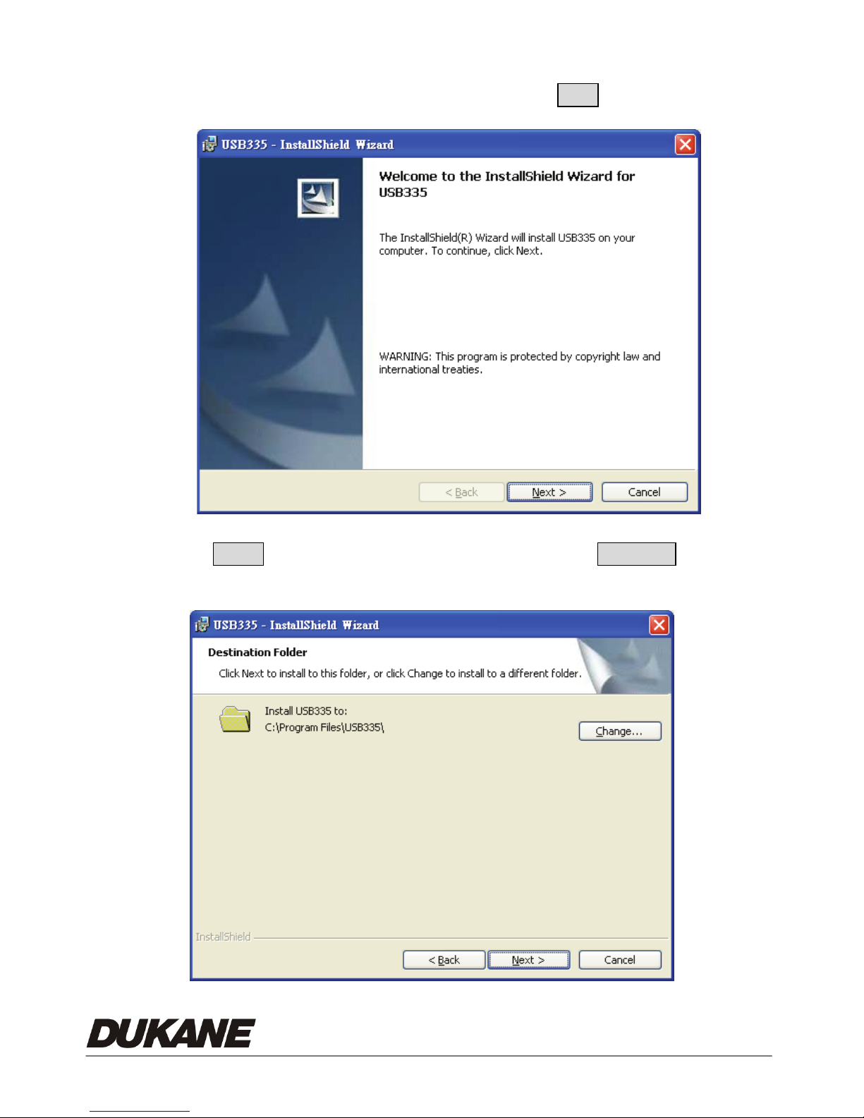
install USB335 please press USB335
5. The installation wizard is shown, please press Next to go next.
6. Click Next to install from the default folder or click Change to specify a
difference.
19
Page 22
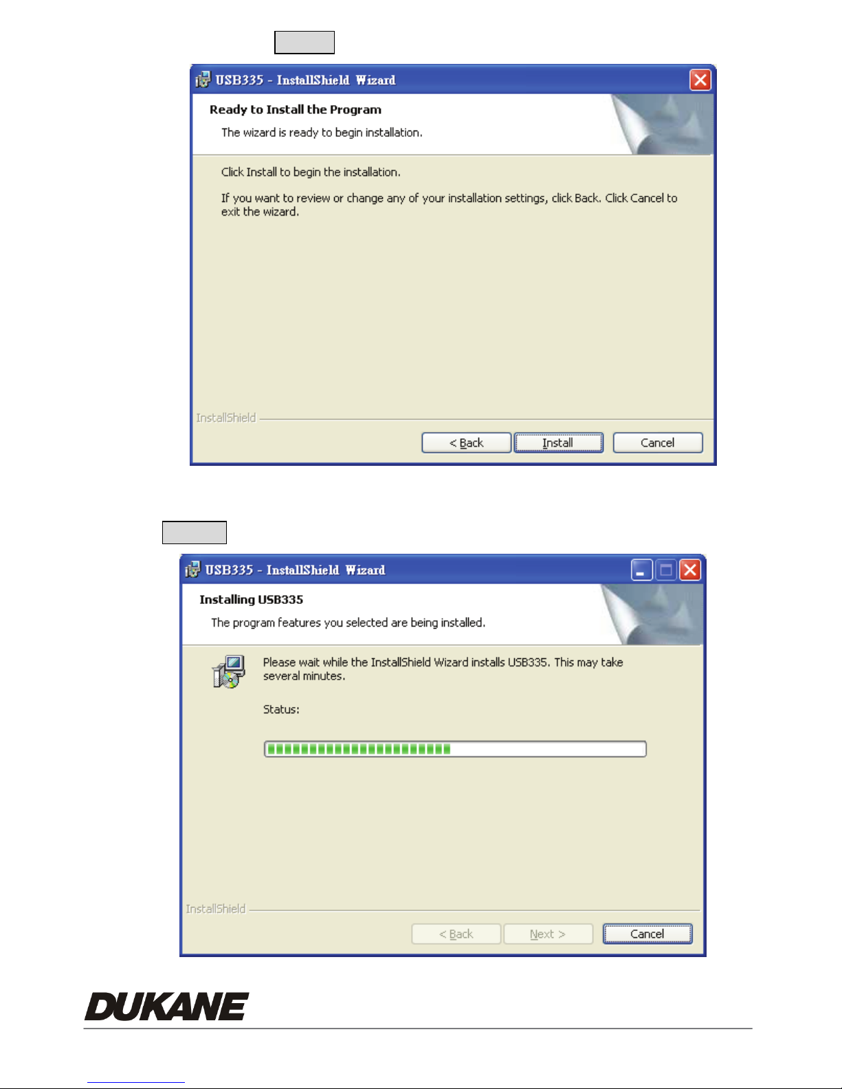
7. Please press Install to begin installation.
8. The installation is processing, if you would like to cancel, please press
Cancel to stop installation.
20
Page 23
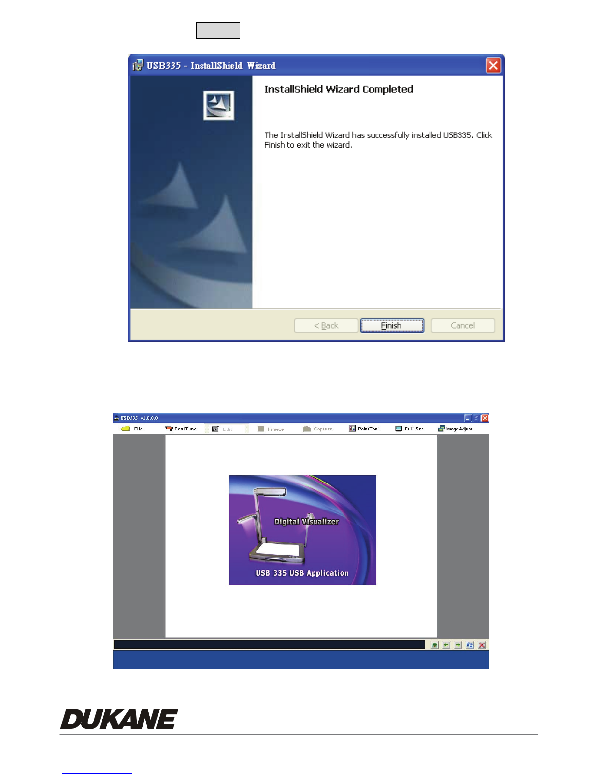
9. Please press Finish to complete the installation.
10. After installation, the USB335 is launched automatically or you may go to
the PC “Start”, and look at “All Programs” to find USB335.
21
Page 24

6.2 Functions (USB335 Software)
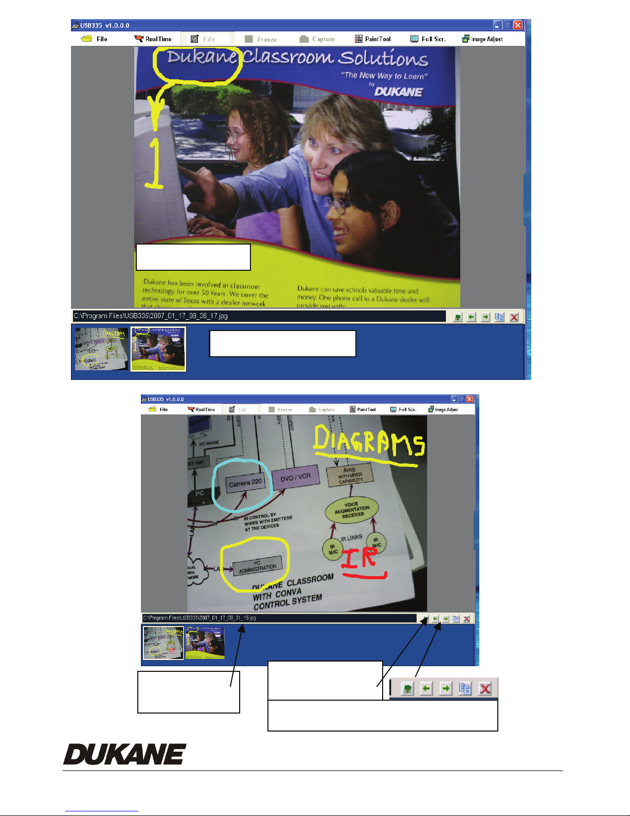
The USB335 software operates with the Camera connected to the computer
using a USB cable. Stored or live images can be viewed on the computer monitor
while the live image from the camera is simultaneously projected. This is possible
by connecting the camera VGA or DVI output to the projector.
The “USB335” software permits the annotation, capture, and storage of a set of
images in project form. This project can be stored and later recalled for viewing or
editing. The editing can modify the images or add new images to the project file.
The entire project file can be converted (imported) to a set of PowerPoint slides by
using the “Export to PPT” command.
At any time all the images stored in the camera memory can be copied to the
“Preview Window” and will be shown as thumbnails. This operation uses the
“Import From Device” command on the “File” menu. Any image can be selected for
annotation and the image order changed for future showing. The camera retains
the original images in its memory.
The functions for the various operations are described in the following sections.
To use the display or editing functions images and projects can be recalled from the
computer memory without the camera being turned on.
The Main Window permits the annotation of the image by using the “Paint Tool”.
The image can be Frozen, Captured in a JPG file, and also enlarged to full screen
size. If it is live from the camera them any camera modification, such as “Flip” will
appear. If the image is from a file, then the image can only be changed by
annotation.
The lower “Preview Window” show thumbnails of images stored in the Project
file. A tool bar above the lower Preview Window permits the insertion of added
images from the file, change of the image order, saving the image as a JPG in the
project folder, and removal of the image from the Preview Window.
22
Page 25
Preview window
Image File
23
Tool bar - Preview
Insert image, move, Save as, & delete
Page 26
Top window tool bar Functions
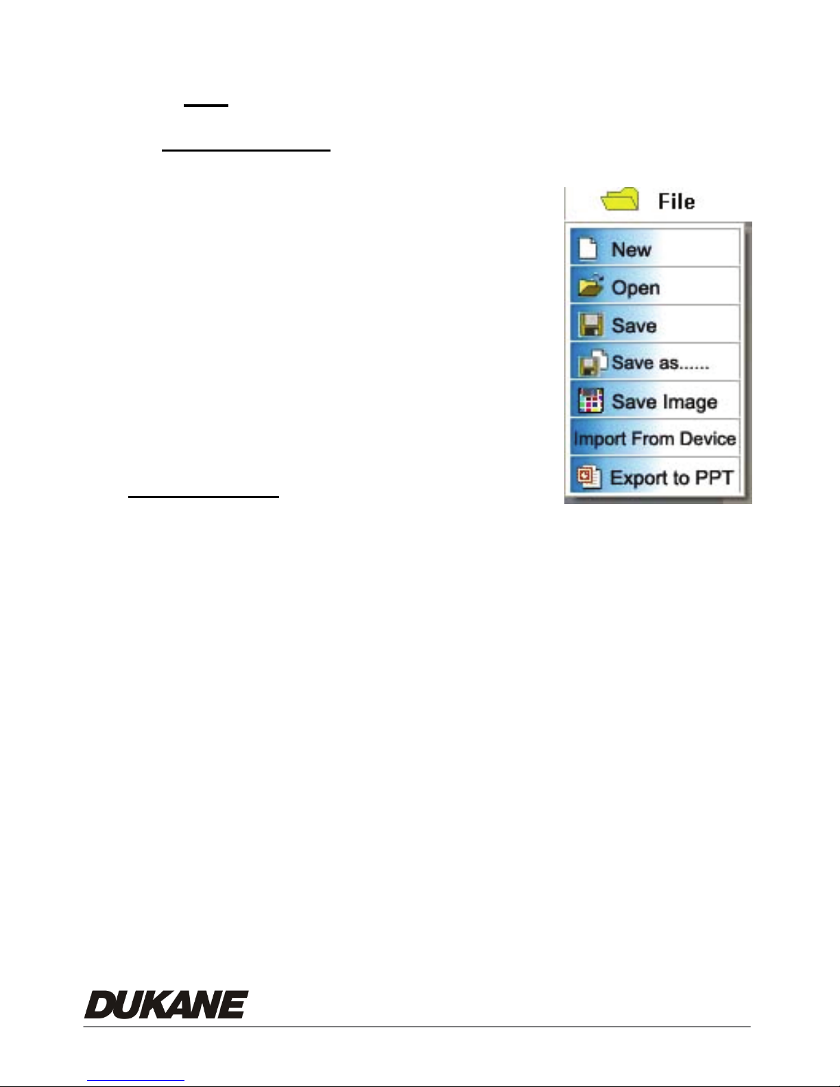
6.2.1 File ( Folder Icon)
Initial Window
z New:Open new project. A blank white display is
(Before Camera Image is Present)
presented in the main window.
z Open:Open a project in a stored file such as the
USB335 Folder. Project files are “mr2” format.
z Import From Device: (Camera)
Transfer copies of all the images from the
camera memory.
Full Operation
• New:Open new project. A blank white display is presented in the main
window.
z Open:Open a project in a stored file such as the USB335 Folder. Project
files are “mr2” format.
z Save:Saves the current project and all the images without opening any file
window.
z Save As:Save all images to a project file (mr2). This includes the main
window images and all the images in the Preview Window. Opens a
“Save as File Window”.
z Save Image:Saves the main window image as a JPG file in the USB335
folder. Opens a “Save as File Window.”
24
Page 27
z Import From Device: (Camera) Imports copies of all the images in the
camera memory. This can be up to 64 images. Places the images as
thumbnails in the lower Preview Window.
• Export to PPT: Saves the entire project in a PowerPoint file with each
image appearing as a separate slide.
6.2.2 Real time (Live Camera image)
Brings the live image from the camera to the Main window. This image can be
annotated by using the “Paint Tool”. It can also be Frozen, Captured, shown
Full Screen, or adjusted by the “Image Adjust “ commands, or the camera
controls.
If the image can’t be displayed normally in the real time mode, please check
the connection between the computer and camera.
6.2.3 Edit mode
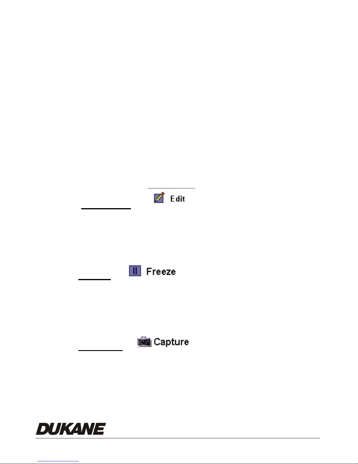
Functions possible while in this mode are File, Paint tool and Full screen.
The Freeze and capture operations are not available in edit mode.
The lower Preview window tool bar appears during the Edit mode.
6.2.4 Freeze
The image can be frozen while in the real time mode.
(*This function is only available in real time mode)
6.2.5 Capture
You can capture images which are saved as JPG files in the default folder as
C:\Program File\USB335\, This function is only available in the real time
mode. “Save JPEG image “ window opens.
25
Page 28
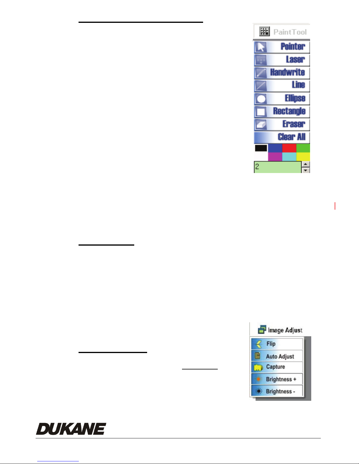
6.2.6 Paint tool ( Annotation)
This is a basic annotation or drawing tool, it can be used
in the real time and the edit modes, right click for tool,
left click to mark any region in the image.
1. Pointer:Mouse pointer
2. Laser:Click Laser to show a spot on the screen
3. Handwrite:Click and drag to draw a line or
annotate
4. Line:Click and drag to draw a line
5. Ellipse:Click and drag to draw a circle
6. Rectangle:Click and drag to draw a rectangle
7. Eraser:Click and drag to clear lines
8. Clear all:Clear all lines on the picture
9. Color:Choose the line color
10. Thickness:Choose thickness of lines. (1 to 99)
6.2.7 Full Screen
The image can be increased to full screen with the "full screen" function. It is
available in Real time mode, and Edit mode. Right -click on the picture and
then the paint tool will appear.
Use "ESC" to return to normal size window.
In the "Edit Mode" the lower Preview Area images can be selected with the
mouse cursor and clinking on the thumbnail image.
6.2.8 Image adjust (For the live image)
This permits adjustment of the live image
displayed in the main window.
Flip:
Rotate the image by 180 degrees
26
Page 29
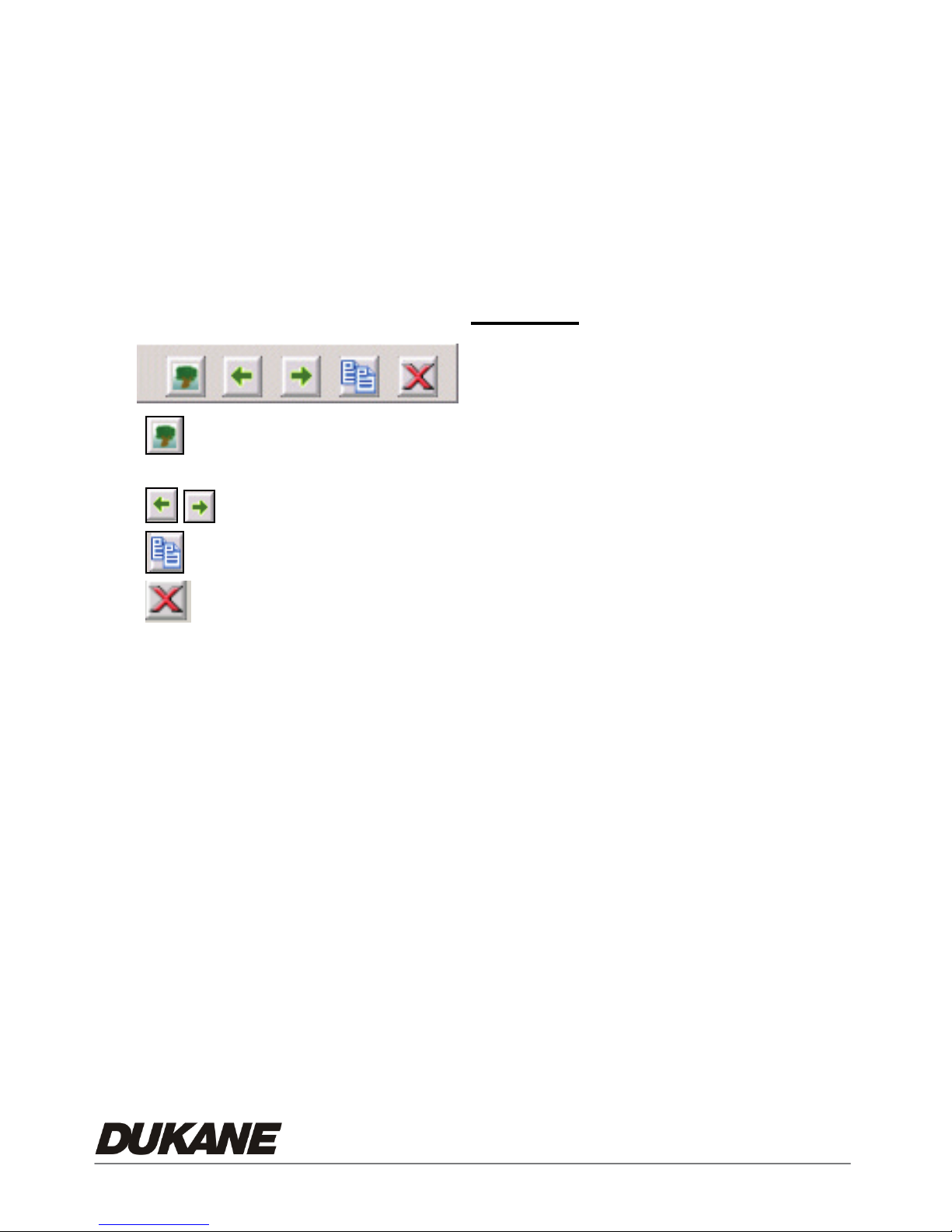
Auto Adjust:
Auto-adjust for the optimum image
Capture:
Capture the image in the camera memory
Brightness +:
Make the image brighter
Brightness -
Make the image darker
:
6.2.9 Image preview view Tool Bar
:Insert a new picture from a JPG image file into the Preview Window.
Bring in a picture from the USB335 folder. “Open JPEG Images”
:Change picture order in the Preview Window.
:Copies image to JPG file . Opens “Save JPEG image” window.
:Delete picture in Preview window only. Still in original file.
27
Page 30
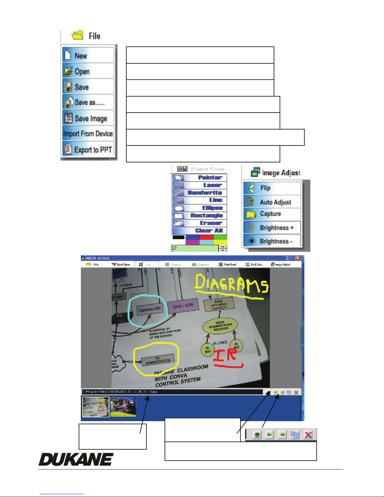
Menus for Operation
Image File
28
Preview window
Preview Window
Insert image, move, Save as, & delete
Page 31
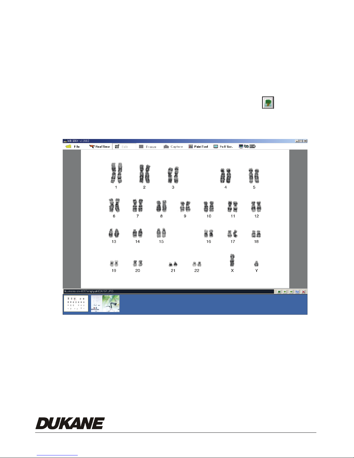
6.3 Operation Information
6.3.1 Display image:
Real time operation:Import a live image from the Camera.
Import From Device:Import the images that are stored in the Camera.
Will not provide images if memory is empty.
Edit model open old file:Use Preview Window tool(
old file in edit mode. Use the File/ Open, to open a project.
)to open an
29
Page 32
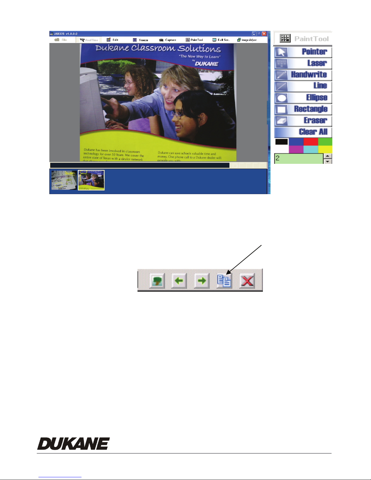
6.3.2 Edit image: Annotation
Annotate; :Click any tool in the “paint tool” menu to modify the image.
Edit and save:After editing picture, click the small picture icon in the
preview area tool bar, and then save the picture.
6.3.3 USB335 Software Menus
30
Page 33
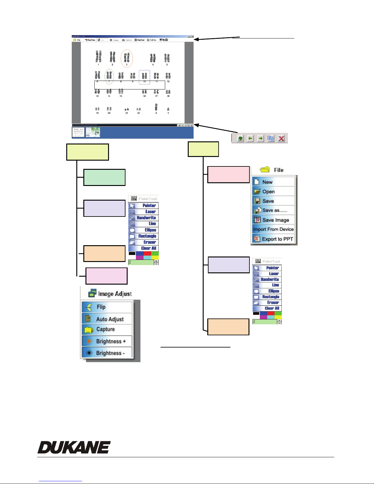
USB335 SOFTWARE MENU
Main Display Window
Tool Bar Functions
File
Real Time
Edit
Freeze
Capture
Paint Tool
Full Screen
Image Adjust
Real Time
Freeze
Paint Tool
Full screen
Image Adjust
Preview Window Images
Tool Bar for Preview Window
Edit
File
Paint Tool
31
Full screen
Files: USB335 Folder
mr2 ho lds Pro ject image list
JPG for the Images
Page 34

Chapter 7 Troubleshooting
If none of the following suggested solutions solves the problem, call your dealer or your
service center.
Problem 1: No picture from the Camera.
Solution -
Wait a few seconds, press desired source selector again.
1.
2. Press a different source, then press-desired source again.
3. Check if the power is turned on. (Is the Pilot Light On?)
4. Make sure the document or object is positioned under the camera
5. If in USB operation disconnection and then reconnect the USB Cable.
Problem 2: Cannot Focus, camera will not focus properly.
Solution - To properly focus: Move Camera head further away from object. Focus and
then move toward the object while pressing the auto focus button
Problem 3: Image is too bright or dark. The desired part of the image can not be seen
because it is too bright or dark.
Solution – Adjust the brightness “BRT+/- “ Control Button on the remote control.
* The updated information will be regularly released on the Dukane web site, please
visit our web site http://www.dukcorp.com/av
.
32
Page 35
USB335 SOFTWARE MENU
Main Display Window
Tool Bar Functions
File
Real Time
Edit
Freeze
Capture
Paint Tool
Full Screen
Image Adjust
Real Time
Freeze
Paint Tool
Full screen
Image Adjust
Preview Window Images
Tool Bar for Preview Window
Edit
File
Paint Tool
2900 Dukane Drive
St. Charles, Illinois 60174
www.dukcorp.com/av
Full screen
Files: USB335 Folder
mr2 ho lds Pro ject image list
JPG for the Images
Audio Visual Products
Toll-free: 800-676-2487
Fax: 630-584-5156e-mail:
[email protected]
#401-335-00
 Loading...