

Page 1
1
Projector
User's Manual (detailed)
Network Guide
Thank you for purchasing this product.
This manual is intended to explain only the network function. For proper use of this
product, please refer to this manual and the other manuals for this product.
Features
This projector has the network function that brings you the following main features.
WARNING
• The information in this manual is subject to change without notice.
• The illustrations in this manual are for illustrative purposes. They may differ
slightly from your projector.
• The manufacturer assumes no responsibility for any errors that may appear in
this manual.
• The reproduction, transfer or copy of all or any part of this document is not
permitted without express written consent.
NOTE
ü Network Presentation : allows the projector to project computer images transmitted
through a network. (
&77)
ü Web Control : allows you to monitor and control the projector through a network from a
computer. (
&37)
ü My Image : allows the projector to store up to four still images and project them. (
&81)
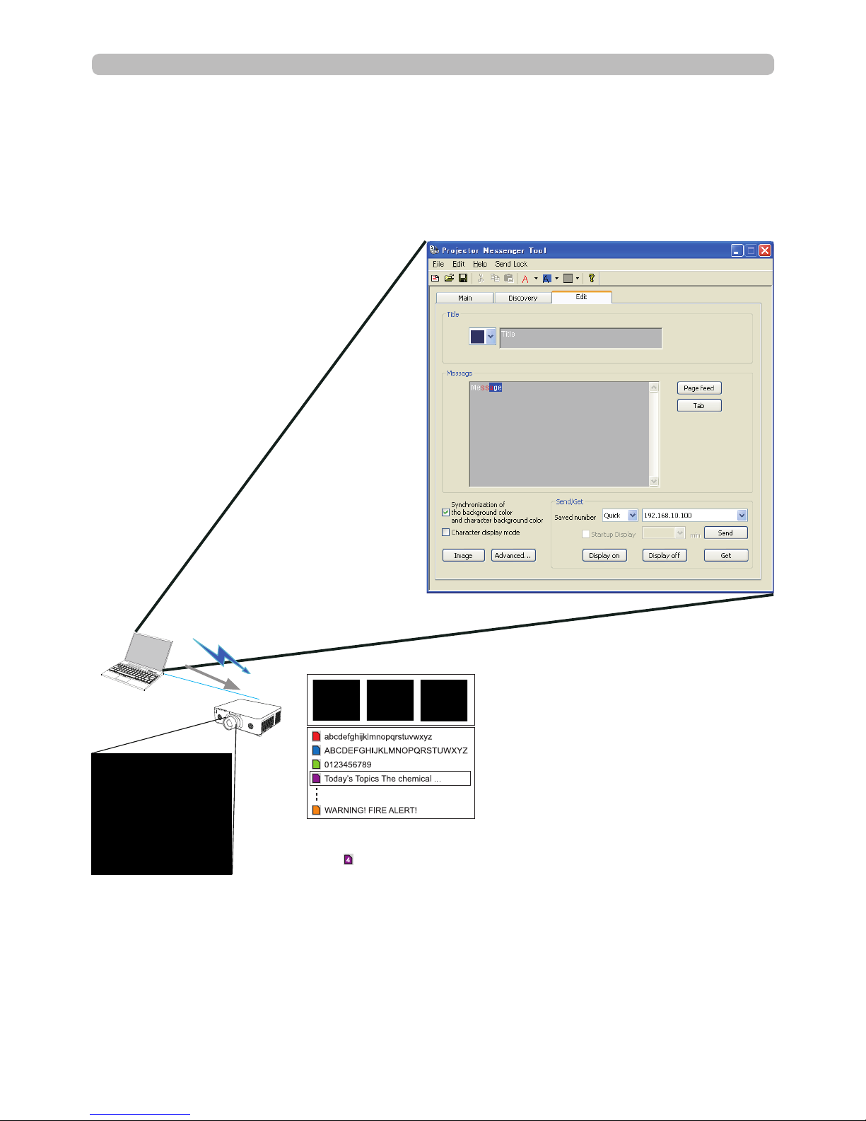
ü Messenger : allows the projector to display text sent from a computer through a network.
(
&82)
ü Network Bridge : allows you to control an external device through the projector from a
computer. (
&85)
8980WU/8983W
8981/8984WU/8982W
►Before using this product, be sure to read all manuals for this
product. After reading them, store them in a safe place for future reference.
430-8980WU-8981-8982W-8983W-8984WU-Net-00
Page 2

2
Contents
Contents
&
Caution .......................................................................................... 4
1. Network Function ..................................................................... 5
1.1 Web Control ................................................................................................ 5
1.2 Network Presentation . ................................................................................ 6
1.3 My Image Function ..................................................................................... 7
1.4 Messenger Function ................................................................................... 8
1.5 Network Bridge Function ............................................................................. 9
1.6 Other Functions ......................................................................................... 10
1.6.1 E-mail Alerts ................................................................................................................... 10
1.6.2 Projector Management using SNMP .............................................................................. 10
1.6.3 Event Scheduling ........................................................................................................... 10
1.6.4 Command Control via the Network ................................................................................ 10
2. Connection to the network .................................................... 11
2.1 System requirements ............................................................................... 11
2.2 Connection via wired LAN ......................................................................... 12
2.3 Connection setup of Wired LAN ............................................................... 12
2.4 Connection via wireless LAN .................................................................... 14
2.4.1 Connection in Simple Access Point Mode ..................................................................... 15
2.4.2 Connection in Infrastructure Mode ................................................................................. 16
2.5 Applications .............................................................................................. 18
2.6 NETWORK Menu . .................................................................................... 20
3. Web Control ............................................................................ 37
3.1 Projector Web Control ............................................................................... 39
3.1.1 Login .............................................................................................................................. 39
3.1.2 Network Information ....................................................................................................... 40
3.1.3 Network Settings ............................................................................................................ 41
3.1.4 Port Settings .................................................................................................................. 46
3.1.5 Mail Settings .................................................................................................................. 48
3.1.6 Alert Settings .................................................................................................................. 50
3.1.7 Schedule Settings .......................................................................................................... 52
3.1.8 Date/Time Settings ......................................................................................................... 56
3.1.9 Security Settings ............................................................................................................ 58
3.1.10 Projector Control .......................................................................................................... 60
3.1.11 Remote Control ............................................................................................................ 64
3.1.12 Projector Status ........................................................................................................... 65
3.1.13 Network Restart ........................................................................................................... 66
3.1.14 Connection Test ........................................................................................................... 67
Page 3

3
Contents
&
3.2 Crestron e-Control
®
.................................................................................. 68
3.2.1 Main window .................................................................................................................... 70
3.2.2 Tools window ................................................................................................................... 72
3.2.3 Info window ..................................................................................................................... 74
3.2.4 Help Desk window ........................................................................................................... 75
3.2.5 Emergency Alert .............................................................................................................. 76
4. Network Presentation ............................................................. 77
4.1 Outline ...................................................................................................... 77
4.2 Display Mode . ........................................................................................... 78
4.2.1 Single PC mode ............................................................................................................. 78
4.2.2 Multi PC mode ............................................................................................................... 78
4.3 Multi Projector Mode . ............................................................................... 79
4.4 Moderator Control Mode . ......................................................................... 79
4.5 Port Number . ............................................................................................ 80
5. My Image Function ................................................................. 81
6. Messenger Function ............................................................... 82
6.1 Outline ...................................................................................................... 82
6.2 Supported Languages .............................................................................. 83
6.3 Display Style ............................................................................................. 83
7. Network Bridge Function ....................................................... 85
7.1 Connecting devices .................................................................................. 85
7.2 Communication setup ............................................................................... 86
7.3 Communication port ................................................................................. 86
7.4 Transmission method ............................................................................... 87
7.4.1 HALF-DUPLEX .............................................................................................................. 87
7.4.2 FULL-DUPLEX ............................................................................................................... 88
8. Other Functions ...................................................................... 89
8.1 E-mail Alerts ............................................................................................. 89
8.2 Projector Management using SNMP ........................................................ 92
8.3 Event Scheduling ..................................................................................... 94
8.4 Command Control via the Network .......................................................... 97
8.5 Crestron Connected
TM
............................................................................ 102
9. Troubleshooting ................................................................... 103
10. Warranty and after-sales service ...................................... 112
Page 4

4
Caution
Caution
To use the wireless network function of this projector, the designated USB wireless adapter sold as an option is required. For precautions according to the standards and laws, refer to the documents that come with the adapter.
[Restriction on plugging and unplugging the USB wireless adapter]
Before you insert or pull out the USB wireless adapter from the projector, turn off
the power of the projector and pull out the power cord’s plug from the outlet. Do
not touch the USB wireless adapter that is connected to the projector while the
projector is receiving AC power.
Do not use any extension cable or device when connecting the adapter to the projector.
[Security precautions when using wireless LAN]
It is recommended that security settings, such as SSID and ENCRYPTION, are
specied when using wireless LAN communication. If the security settings are not
specied, the contents may be intercepted or it may cause unauthorized access
to the system. For details on wireless LAN security settings, refer to 3.1 Projector
Web Control.
►The optional IEEE802.11b/g/n USB wireless adapter uses the 2.4GHz radio
frequency band. You do not need a radio license to use the adapter, but you
should be aware of the following:
• DO NOT USE NEAR THE FOLLOWING!
• Microwave ovens
• Industrial, scientic or medical devices
• Designated low power radio stations
• Premises radio stations
Using the USB wireless adapter near the above may cause radio interference,
which would result in a decrease in transmission speed or interruption, and
even lead to malfunctioning of devices such as pacemakers.
• Depending on the location where the USB wireless adapter is used, radio wave
interference may occur, which may result in a decrease in transmission speed
or interruption in communication. In particular, please be aware that using the
USB wireless adapter at locations where there is reinforced steel, other types of
metals or concrete is likely to cause radio wave interference.
• Available Channels
The USB wireless adapter uses the 2.4GHz radio frequency band, but
depending on the country or region you are in, the channels that you can use
might be limited. Please consult your dealer for information on the usable
channels.
• Bringing the optional USB wireless adapter out of the country or region you
reside in and using it there could lead to a violation of the radio laws of that
country or region.
CAUTION
Page 5
5
1. Network Function
1. Network Function
This chapter describes the outline of network function.
Connecting the projector and the computer via the network, remote control and
status monitoring of the projector can be performed by Web browser.
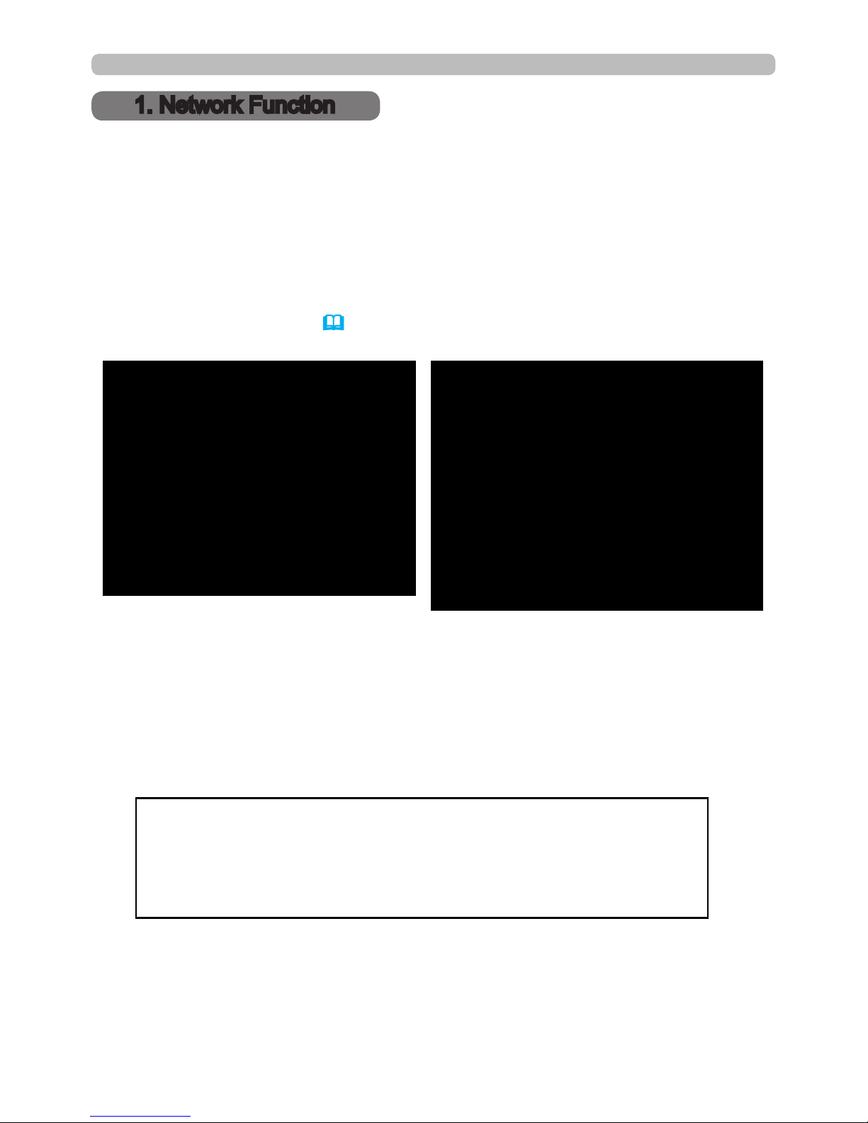
Two types of interface, ”Projector Web Control” and “Crestron e-Control”, are
available for this projector. (
&37)
1.1 Web Control
Projector Web Control Crestron e-Control
Note: The Dukane models described in this document are manufactured by
Hitachi and use the same rmware, software programs, control code, and
accessory parts. The equivalent Dukane to Hitachi models are; 8980WU
(CP-WU8700), 8981 (CP-X8800), 8982W(CP-WX8650), 8983W (CPWX8750) and 8984WU (CP-WU8600).
Page 6
6
1.2 Network Presentation
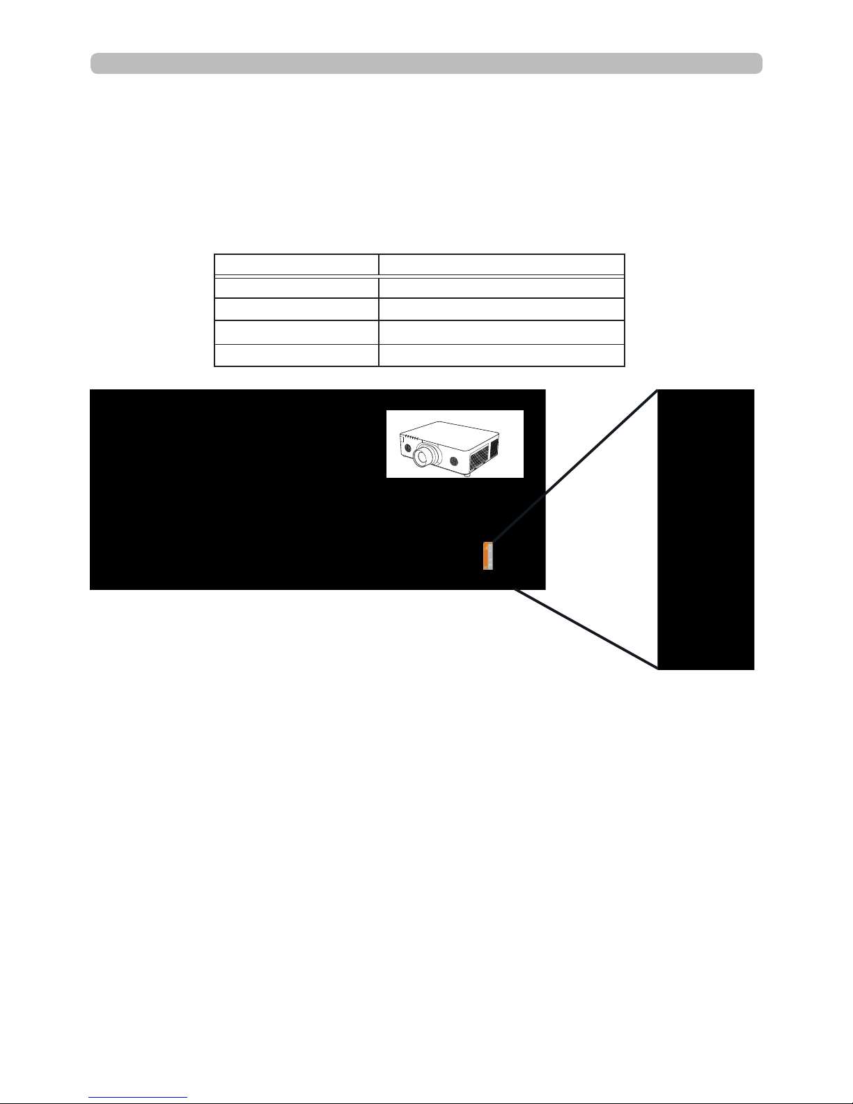
The projector can display or play back the computer screen images and audio
data that are transmitted through the network.
To use Network Presentation, an exclusive application, "LiveViewer" is required.
The following application is required to use Network Presentation.
1. Network Function
OS Application
Windows LiveViewer
Mac OSX LiveViewer
iOS(iPhone/iPad) Projector Quick Connection
Android Projector Quick Connection
Page 7
7
1.3 My Image Function
1. Network Function
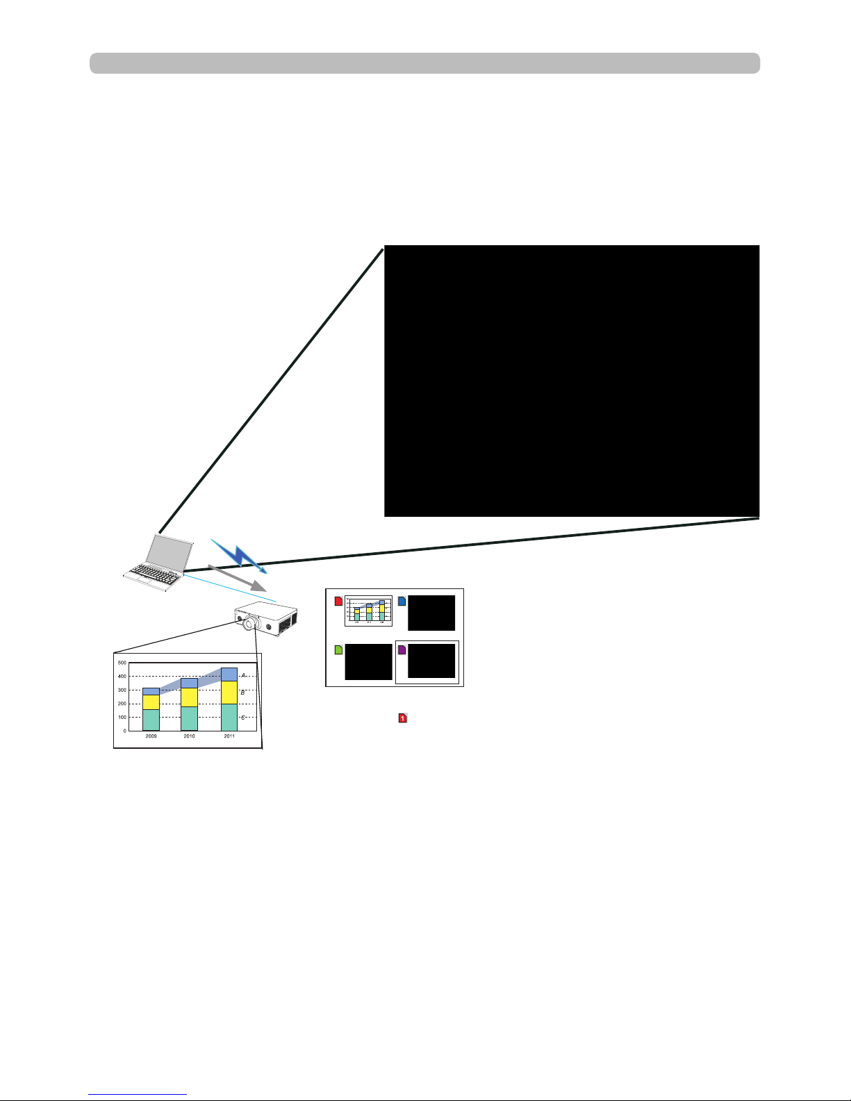
The projector can display still images transferred via the network.
It is possible to allocate up to 4 image les.
MY IMAGE transmission requires an exclusive application for your computer.
Use the application to transfer the image data.
1
43
2
1
43
2
Transfer image data
Display image data (ex.
)
Page 8
8
1.4 Messenger Function
1. Network Function
The projector can display text data transferred via the network on the screen and
play back audio data inside the projector.
It is possible to store up to 12 text data.
Transfer text data
Display text data (ex.
)
1
4
3
2
12
1
4
3
2
12
Page 9
9
1.5 Network Bridge Function
1. Network Function
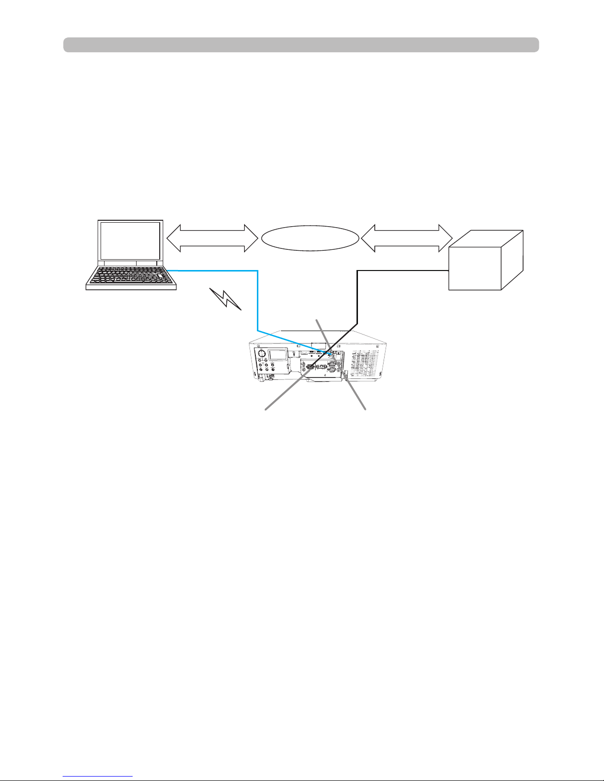
This projector is equipped with the NETWORK BRIDGE function to perform
mutual conversion of a network protocol and a serial interface.
By making use of the NETWORK BRIDGE function, a computer connected to the
projector via wireless or wired LAN is able to control an external device via
RS-232C communication using the projector as a network terminal.
RS-232C
RS-232C cable
CONTROL port LAN port
External device
Wired LAN
LAN cable
Computer
Protocol change
TCP/IP data Serial data
WIRELESS port
(USB wireless
adapter)
Wireless
LAN
Page 10

10
1.6 Other Functions
1. Network Function
The projector can automatically send an alert message to the specied e-mail
addresses when the projector detects a certain condition that is requiring
maintenance or detected an error. (&89)
1.6.1 E-mail Alerts
The SNMP (Simple Network Management Protocol) enables to manage the
projector information, which is a failure or warning status, from the computer on
the network. The SNMP management software will be required on the computer
to use this function. (
&92)
1.6.2 Projector Management using SNMP
The scheduling function enables to setup scheduled events including
power on / power off. It enables to be “self-management” projector.
The schedule can be set in Projector Web Control or OPTION-SCHEDULE menu
in the projector. (
&94)
1.6.3 Event Scheduling
You can congure and control the projector via the network using RS-232C
commands. (
&97)
1.6.4 Command Control via the Network
Page 11
11
2. Connection to the network
2.1 System requirements
2. Connection to the network
The following equipments are required to connect the projector to your computer
through the network.
■ Common The projector: 1 unit, Computer: 1 or more sets
■ Connecting device for the projector and the computer
1) For the wired connection *1
LAN cable (CAT-5e or greater): 1 piece
2) For the wireless connection *2
- Projector side
IEEE802.11b/g/n USB wireless adapter (option : USB-WL-11N): 1 unit
*3
- Computer side
IEEE802.11b/g/n wireless LAN equipment: 1 unit for each computer *4
*1: The system for using the network function of the projector requires
communication environment conforming to 100Base-TX or 10Base-T.
*2: An access point is required when the wireless LAN connection is used as
Infrastructure mode.
*3: Available encryption methods are as follows. This product cannot be
connected to the wireless network using other encryption method.
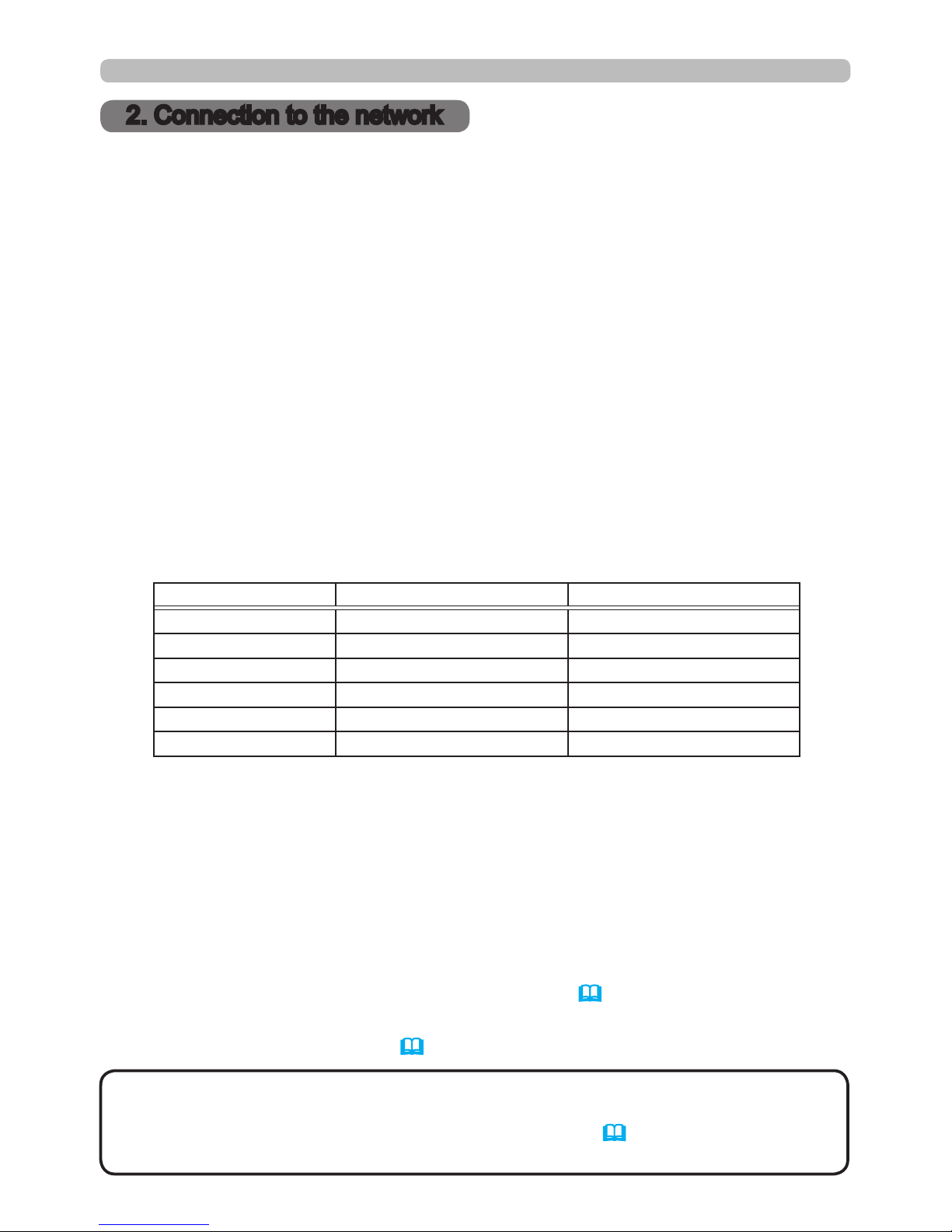
Simple Access Point mode Infrastructure mode
WPA2-PSK (AES)
✓ ✓
WPA2-PSK (TKIP)
✓ ✓
WPA-PSK (AES)
✓ ✓
WPA-PSK (TKIP)
✓ ✓
WEP 128bit -
✓
WEP 64bit -
✓
*4: Depending on the type of wireless network device and computer you are using,
the projector may not be able to communicate properly with your computer,
even if the computer is equipped with a built-in wireless LAN function.
To eliminate communication problems, use a Wi-Fi certied wireless network
device.
■ Web browser
Web browser is required to be installed in your computer to use Web control.
■ Application
Exclusive applications are required to be installed in your computer to use
Network Presentation, My Image and Messenger. (
&18)
For Mac users: Mac OS does not support some applications. Refer to System
Requirements for Applications (
&20) rst before setting up the connection.
• The network function is not available when STANDBY MODE is set
to SAVING and the projector is in standby mode. Connect the projector to the
network after setting STANDBY MODE to NORMAL. (&SETUP menu in the
Operating Guide)
NOTE
Page 12
12
2. Connection to the network
2.2
Connection via wired LAN
The connection via wired LAN is available. Set wired LAN for the projector by
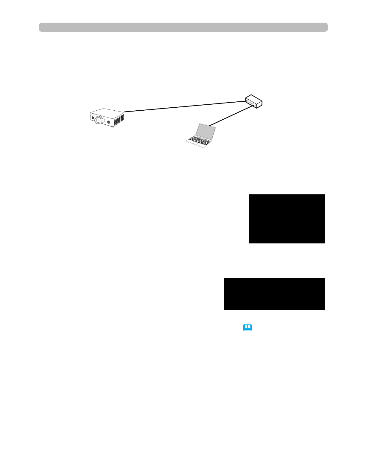
following the instructions of your network administrator when connecting to the
existing network.
1) Connect the projector to the computer via a hub
with a LAN cable (CAT-5e or higher).
2) Press the MENU button on the remote control or the
control panel of the projector.
The MENU you last used will appear.
Use the cursor button to select the following.
EASY MENU > ADVANCED MENU > NETWORK > WIRED SETUP
3) Set the following items in WIRED SETUP.
・ DHCP
・ IP ADDRESS
・ SUBNET MASK
・ DEFAULT GATEWAY
・ DNS SERVER
As for setting an IP address, refer to About IP address. (
&13)
Select APPLY, then press the ENTER button to reect the settings.
2.3
Connection setup of Wired LAN
hub
Page 13

13
•
Although HDBaseTTM and LAN port can be used for wired LAN, they cannot be
used simultaneously.
Connect LAN cable to the port set in WIRED NETWORK
on NETWORK menu.
•
The same network address cannot be used for both wireless LAN and wired LAN.
•
If the projector and the computer exist in the same network (i.e., same network
address), you can leave the default gateway eld blank.
• When the projector and the computer exist in different networks, the default
gateway must be set. Consult to the network administrator in detail.
NOTE
2. Connection to the network
[About IP address]
■ Setting manually
The Network address portion of the IP address setting on your computer must
be the same as the setting on the projector. Also, the entire IP address on the
computer must not overlap with that of the other devices on the same network,
including the projector.
The projector’s settings are as follows.
IP address: 192.168.1.254
Subnet mask: 255.255.255.0
(Network address: 192.168.1 in this case)
Therefore, specify the computer’s IP address as follows.
IP address: 192.168.1.xxx (xxx shows decimal number.)
Subnet mask: 255.255.255.0
(Network address: 192.168.1 in this case)
For example
Select from 1 to 254 for “xxx” not duplicating with any other equipments.
In this case, since the IP address of the projector is “192.168.1.254”, specify a
setting between 1 to 253 for the computer.
■ Setting automatically
When a DHCP server exists in the connected network, it assigns an IP address
to the projector and the computer automatically. If DHCP server is not available,
set IP ADDRESS, SUBNET MASK and DEFAULT GATEWAY.
Page 14
14
2. Connection to the network
2.4
Connection via wireless LAN
Connection via wireless LAN is available with option parts, USB wireless adapter
(USB-WL-11N).
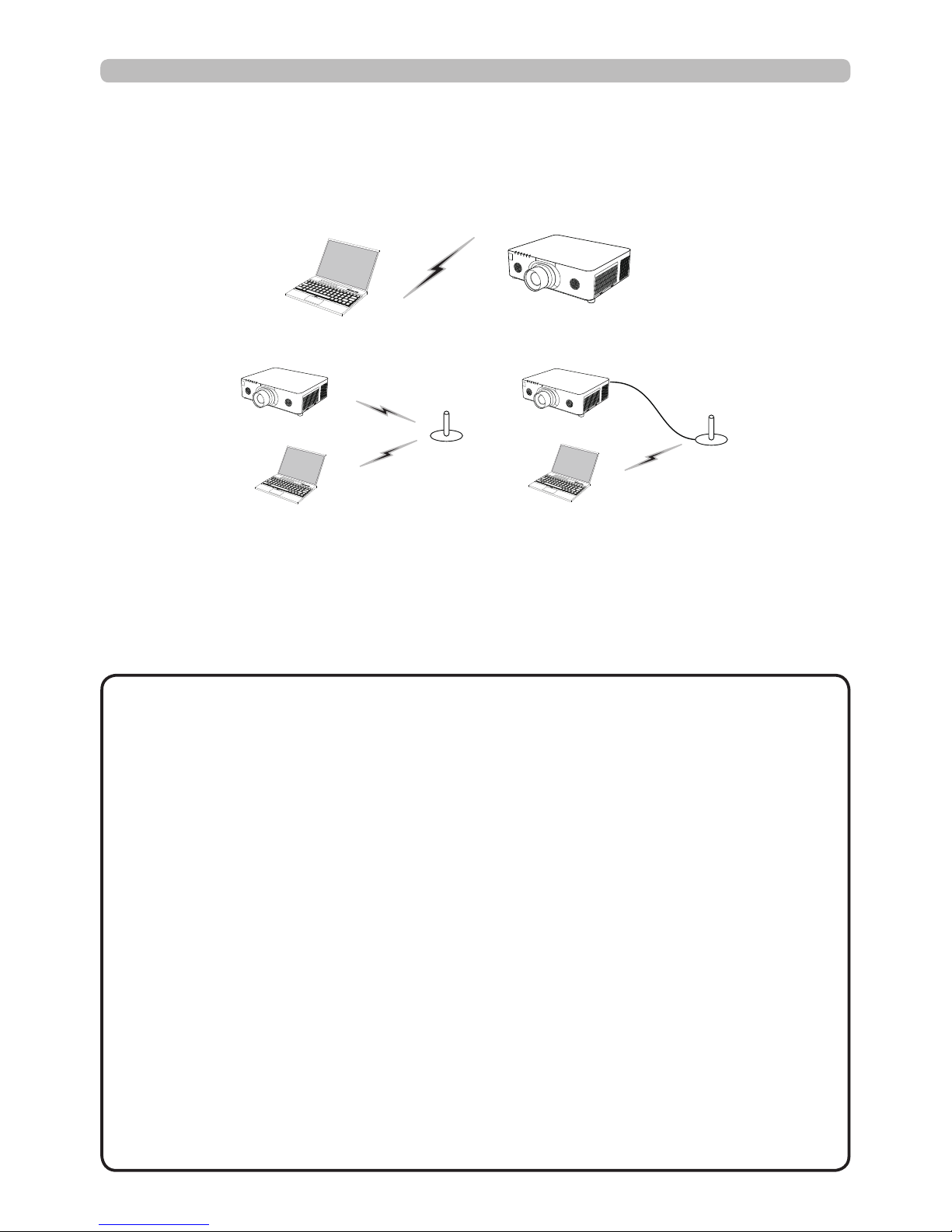
Wireless LAN has two types of connection, Simple Access Point and
Infrastructure.
* SIMPLE ACCESS POINT is a mode which connects to computers directly.
This projector can assign IP addresses to up to 11 devices.
* Infrastructure is one of the wireless LAN communication methods with having
an access point to communicate. If communicating with existing network, consult
with your network administrator.
Fig. 2.4.a Without an access point communication (Simple Access Point)
Fig. 2.4.b With an access point communication (Infrastructure)
• Network settings can also be changed in Network Settings of Projector Web
Control.
• Wireless LAN initial settings for the projector are as follows.
Mode: Simple Access Point
DHCP: Off
IP address: 192.168.10.1
Subnet Mask: 255.255.255.0
Default Gateway: 0.0.0.0
DNS Server: 0.0.0.0
SSID: SimpleAccessPoint ※
SSID Broadcast: On
Encryption: Off
Channel: 11
※ Change default setting before use not to overlap.
• The same network address cannot be used for both wireless LAN and wired LAN.
• Communication speed of the projector may be deteriorated in SIMPLE ACCESS
POINT mode depending on the number of connected devices.
• Network communication cannot be available between the devices connected to
the projector in SIMPLE ACCESS POINT mode.
NOTE
Page 15

15
2.4.1 Connection in Simple Access Point Mode
Set the following when connecting the projector and the computer in Simple
Access Point mode.
Projector setting
[Restriction on plugging and unplugging the USB wireless adapter]
Before you insert or pull out the USB wireless adapter from the projector, turn off
the power of the projector and pull out the power cord’s plug from the outlet. Do
not touch the USB wireless adapter that is connected to the projector while the
projector is receiving AC power.
Do not use any extension cable or device when connecting the adapter to the
projector
.
1) Attach the USB wireless adapter to the WIRELESS port of the projector.
2) Turn on the projector.
3) Press the MENU button on the remote control or the
control panel of the projector.
The MENU you last used will appear.
Use the cursor button to select the following.
EASY MENU > ADVANCED MENU > NETWORK > WIRELESS SETUP
4) Set the following items in WIRELESS SETUP.
・ MODE: SIMPLE ACCESS POINT
・ IP ADDRESS
・ SSID
・ SSID BROADCAST
・ ENCRYPTION
・ CH
Select APPLY, then press the ENTER button to reect the settings.
• As for the procedure of setting network and wireless connection for the
computer, refer to the manual of computer or wireless LAN device.
About network settings
・ The fourth octet of the projector's IP address is xed to 1.
・ Subnet mask of the projector is xed to 255.255.255.0.
Computer setting
1) The DHCP server function of the projector is always enabled. Enable the DHCP
setting of the computer.
2) Select SSID set for the projector by following the procedure of wireless
connection of the computer. Enter encryption key by following the computer’s
instruction if it is encrypted.
NOTE
2. Connection to the network
Page 16

16
2.4.2 Connection in Infrastructure Mode
Set the following when connecting the projector and the computer in Infrastructure
mode.
[Restriction on plugging and unplugging the USB wireless adapter]
Before you insert or pull out the USB wireless adapter from the projector, turn off
the power of the projector and pull out the power cord’s plug from the outlet. Do
not touch the USB wireless adapter that is connected to the projector while the
projector is receiving AC power.
Do not use any extension cable or device when connecting the adapter to the
projector.
1) Attach the USB wireless adapter to the WIRELESS port of the projector.
2) Turn on the projector.
3) Press the MENU button on the remote control or the
control panel of the projector.
The MENU you last used will appear.
Use the cursor button to select the following.
EASY MENU > ADVANCED MENU > NETWORK > WIRELESS SETUP
4) Set the following items in WIRELESS SETUP.
・ MODE: INFRASTRUCTURE
・ DHCP
・ IP ADDRESS
・ SUBNET MASK
・ DEFAULT GATEWAY
・ DNS SERVER
・ SSID
・ ENCRYPTION
As for setting an IP address, refer to About IP address. (
&13)
Select APPLY, then press the ENTER button to reect the settings.
2. Connection to the network
Page 17

17
•
Transmission speed may be slow depending on the settings of an access point.
•
If the projector and the computer exist in the same network (i.e., same network
address), you can leave the default gateway eld blank.
• When the projector and the computer exist in different networks, the default
gateway must be set. Consult with the network administrator in detail.
• Set wireless LAN for the projector by following the instructions of your network
administrator when connecting to the existing network.
• Open System Authentication is used for WEP encryption, and Shared Key
Authentication is not supported. The authentication with an access point succeeds
and it is regarded that the connection is established normally even when entering
illegal encryption key due to Open System Authentication, but data cannot actually
be transmitted.
• IP ADDRESS, SUBNET MASK, and DEFAULT GATEWAY should be set in
advance when DHCP is set to OFF.
NOTE
The connection can be set up by selecting from SSID SCAN LIST without setting
SSID and ENCRYPTION in WIRELESS SETUP. The procedure of connecting by
SSID SCAN LIST is as follows.
1) Select SSID SCAN LIST in WIRELESS SETUP on NETWORK menu.
The list of SSID in wireless network is displayed.
2) Select SSID in wireless network that you want to connect in SSID SCAN LIST.
The display to enter the encryption key appears if it is encrypted.
Enter the encryption key by using software keyboard.
3) The icon indicating connected ( ) is displayed in SSID SCAN LIST screen
when the connection is complete.
Connection in Infrastructure Mode (continued)
SSID SCAN LIST function
2. Connection to the network
Page 18

18
2.5 Applications
The latest version of the application software can be downloaded from the website
below.
http://www.hitachi-america.us/projectors
http://www.hitachidigitalmedia.com/
http://www.hitachi-dm.cn/
http://www.hitachi.co.jp/proj/
For iOS/Android Network Presentation software, refer to the URL below for details
and downloads of Projector Quick Connection.
http://www.hitachi.co.jp/Prod/vims/proj/en/
http://www.hitachi.co.jp/proj/
[System Requirements for Applications]
Application Hardware and Software
LiveViewer [Windows]
OS:
Windows Vista
®
(Service Pack 1 or later)
Windows 7
Windows 8/8.1
Graphic card:
VGA: 640x480 or higher (recommended XGA: 1024x768)
CPU:
Pentium 4 (2.8 GHz or higher)
Hard disk space:
100MB or higher
2. Connection to the network
Note: The Dukane models described in this document are manufactured by
Hitachi and use the same rmware, software programs, control code, and
accessory parts. The equivalent Dukane to Hitachi models are; 8980WU
(CP-WU8700), 8981 (CP-X8800), 8982W(CP-WX8650), 8983W (CPWX8750) and 8984WU (CP-WU8600).
Page 19

19
[System Requirements for Applications] (continued)
Application Hardware and Software
LiveViewer [Mac]
Mac OSX 10.5
Mac OSX 10.6
Mac OSX 10.7
Mac OSX 10.8
Hard disk space:
15MB or higher
Projector Quick
Connection
[iOS]
iOS 6 or later
[Android]
Android OS 4.0 or later
Projector Image Tool
(PJImg)
OS:
Windows Vista
®
Windows 7
Windows 8/8.1
CPU:
Pentium 3 (500MHz or higher)
Hard disk space:
20MB or higher
Projector Messenger
Tool (PJMessenger)
OS:
Windows Vista
®
Windows 7
Windows 8/8.1
CPU:
Pentium 3 (500MHz or higher)
Hard disk space:
20MB or higher
2. Connection to the network
•
Only for Intel version. Power Mac is not supported.
• LiveViewer
for MAC
CD-ROM.
Download it from the website.
NOTE
Page 20

20
2.6 NETWORK Menu
2. Connection to the network
Remember that incorrect network settings on this
projector may cause trouble on the network. Be sure
to consult with your network administrator before
connecting to an existing access point on your network.
Select “NETWORK” from the main menu to access to
the following functions.
Select an item using the ▲/▼ cursor buttons on the
projector or remote control, and press the ► cursor button on the projector or
remote control, or ENTER button on the remote control to execute the item. Then
perform it according to the following table.
• When you use wired LAN, rst select which function to use, LAN or
HDBaseTTM, in WIRED NETWORK menu.
• To use the wireless network function of this projector, the designated USB
wireless adapter sold as an option is required. Do not use any extension cable
or device when connecting the adapter to the projector.
•
The projector does not allow both wireless and wired LAN to be connected to
the same network.
• Do not set the same network address for both wireless and wired LAN.
• If you do not use SNTP, then you must set the DATE AND TIME during the
initial installation.
• The network function is not available when STANDBY MODE is set to
SAVING and the projector is in standby mode. Connect the projector to the
network after setting STANDBY MODE to NORMAL. (&SETUP menu in the
Operating Guide)
NOTE
Page 21

21
Item Description
PROJECTOR
NAME
Any name can be set to the projector to identify it on the
network.
(1) Select the PROJECTOR
NAME and press the ►
button. The PROJECTOR
NAME dialog will be displayed.
Use displayed software keyboard to enter PROJECTOR
NAME.
DELETE : Deletes one character.
CLEAR ALL: Deletes all characters.
CANCEL : Goes back to network menu after discarding
the entered characters.
OK : Goes back to network menu after saving the entered
characters.
(2) The current PROJECTOR NAME will be displayed on the
rst 3 lines. Particular projector name is pre-assigned by
default.
Use the ENTER or INPUT button to select and enter
characters.
To erase 1 character at one time, press the RESET button
or press the ◄ and INPUT button at the same time. Also if
you move the cursor to DELETE or CLEAR ALL on screen
and push the ENTER or INPUT button, 1 character or
all characters will be erased. Up to 64 characters can be
input for the PROJECTOR NAME.
(3) To change an already inserted
character, move the cursor
to one of the rst 3 lines,
and move the cursor on the
character to be changed.
After pressing the ENTER or
INPUT button, the character is
selected. Then, follow the same
procedure as described at the
item (2) above.
(4) To nish entering text, move the cursor to the OK on
screen and press the ►, ENTER or INPUT button. To
revert to the previous PROJECTOR NAME without saving
changes, move the cursor to the CANCEL on screen and
press the ◄, ENTER or INPUT button.
2. Connection to the network
(continued on next page)
Page 22
22
Item Description
WIRELESS
SETUP
Congures wireless network.
Setting values are saved after
selecting "APPLY".
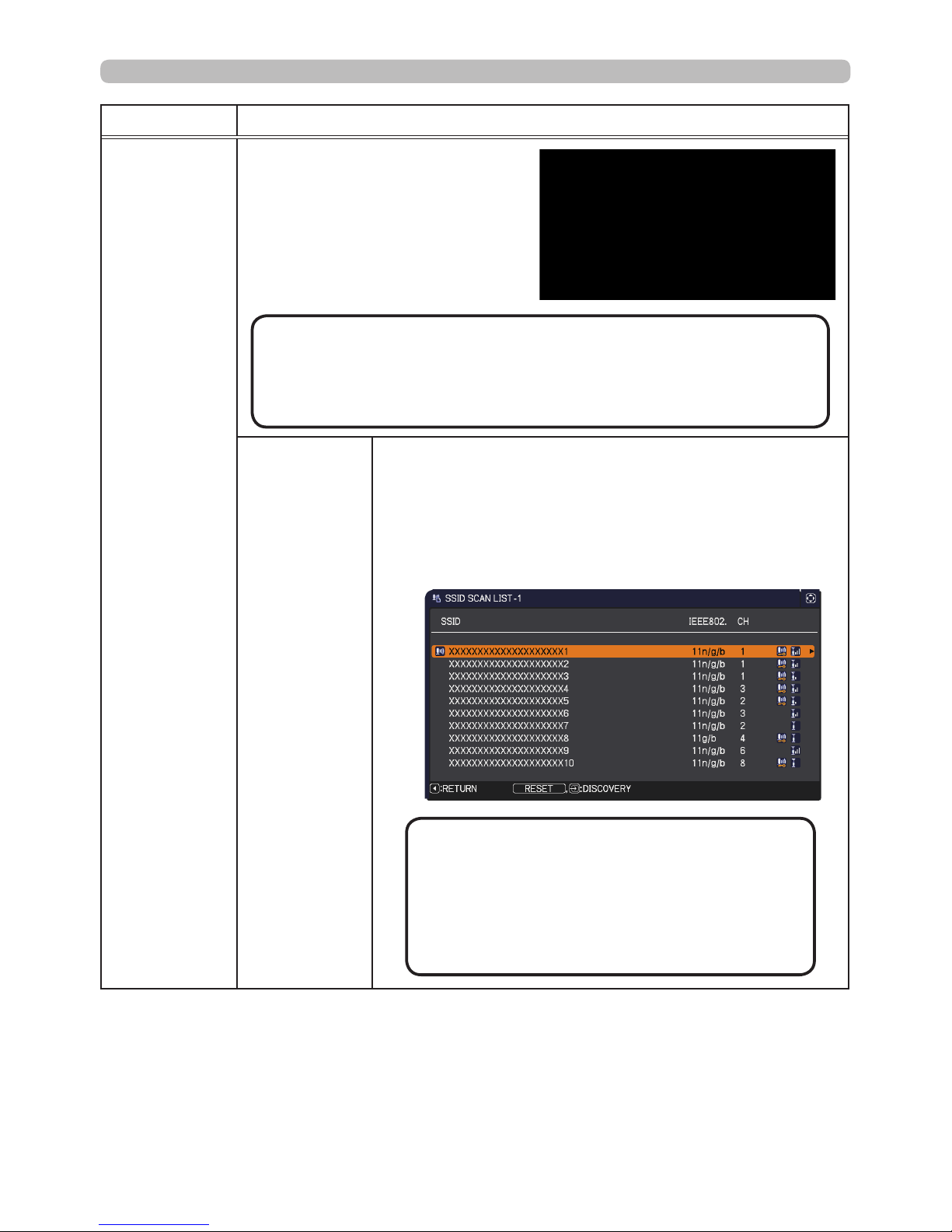
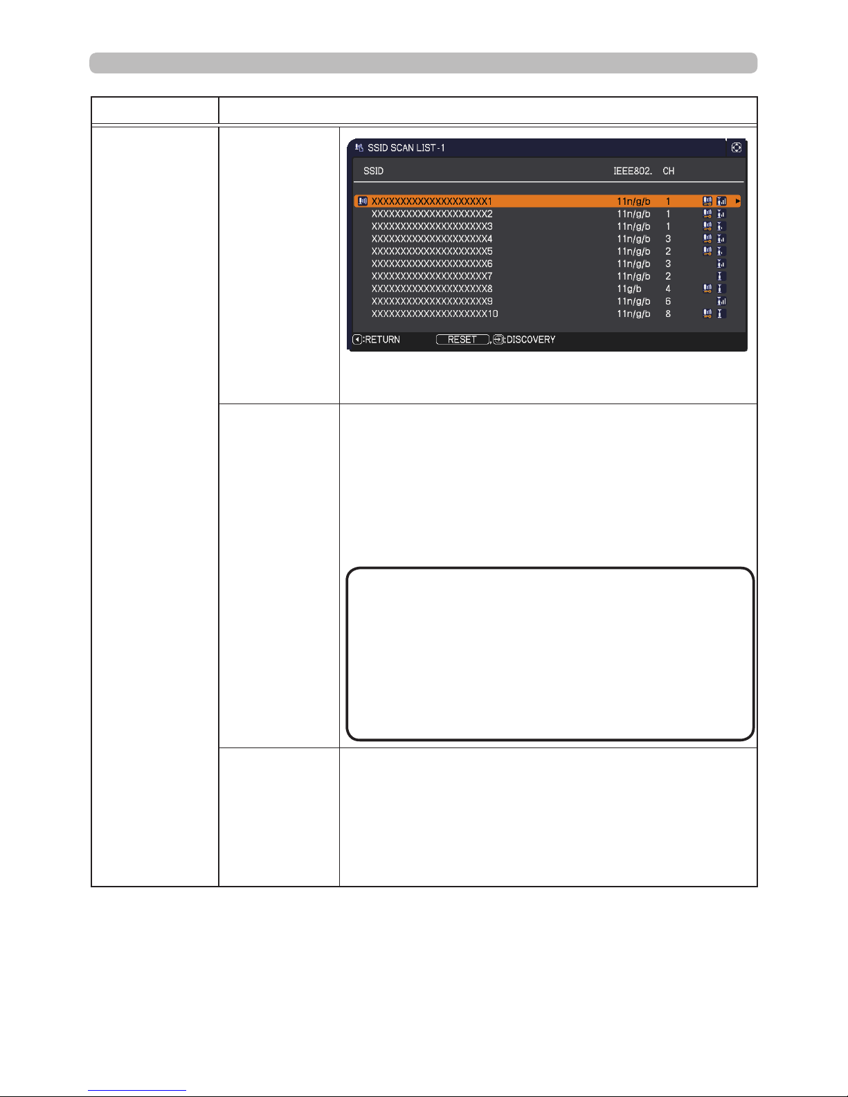
SSID SCAN
LIST
Searches available wireless network and displays
the list of SSID.
You can select SSID to connect from the list.
(1) SSID on available wireless network is
displayed after selecting SSID SCAN LIST and
press the ► button.
(continued on next page)
2. Connection to the network
• Setting values are not saved if Menu dissapears before
selecting "APPLY".
• Be sure to execute "APPLY" after changing the settings.
NOTE
・The wireless network using the encryption
method not supported by the projector is
not displayed in the search list.
・A network device of AdHoc doesn’t be
displayed on SSID SCAN LIST.
NOTE
Page 23
23
Item Description
WIRELESS
SETUP
(continued)
SSID SCAN
LIST
(continued)
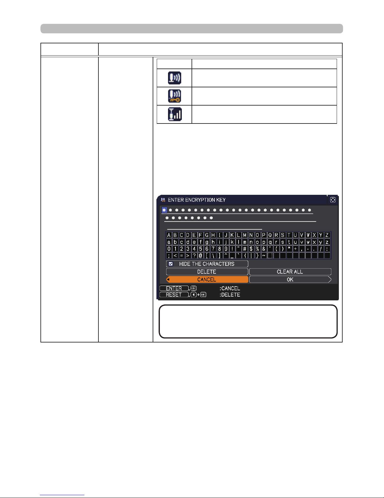
Icon Description
The projector is connecting to the wireless
network.
The wireless network is encrypted.
The intensity of radio wave.
(2) Select SSID that you want to connect and
press the ► or ENTER button. The display
to enter the encryption key appears if SSID
is encrypted. Enter the characters by using
software keyboard.
Move the cursor to OK and press the ►, ENTER
or INPUT button after entering.
(continued on next page)
2. Connection to the network
If you select the [HIDE THE CHARACTERS]
checkbox, the characters are hidden.
NOTE
Page 24
24
Item Description
WIRELESS
SETUP
(continued)
SSID SCAN
LIST
(continued)
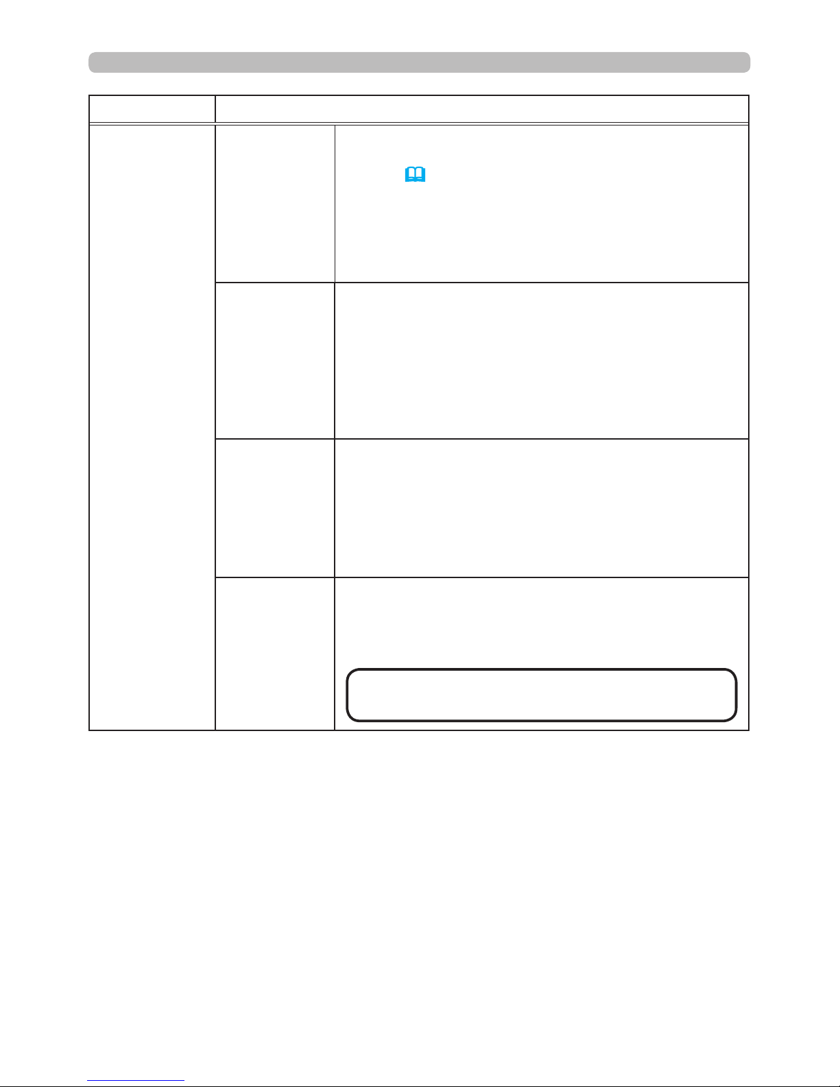
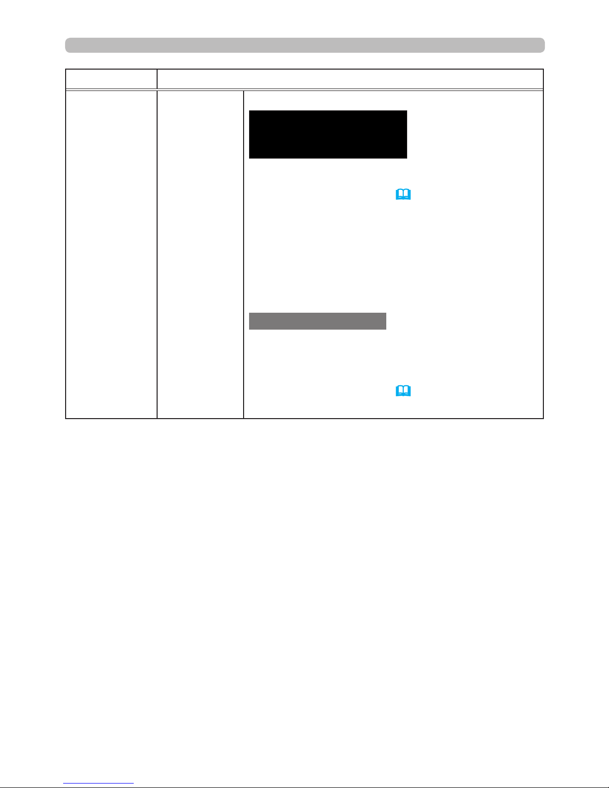
(3)
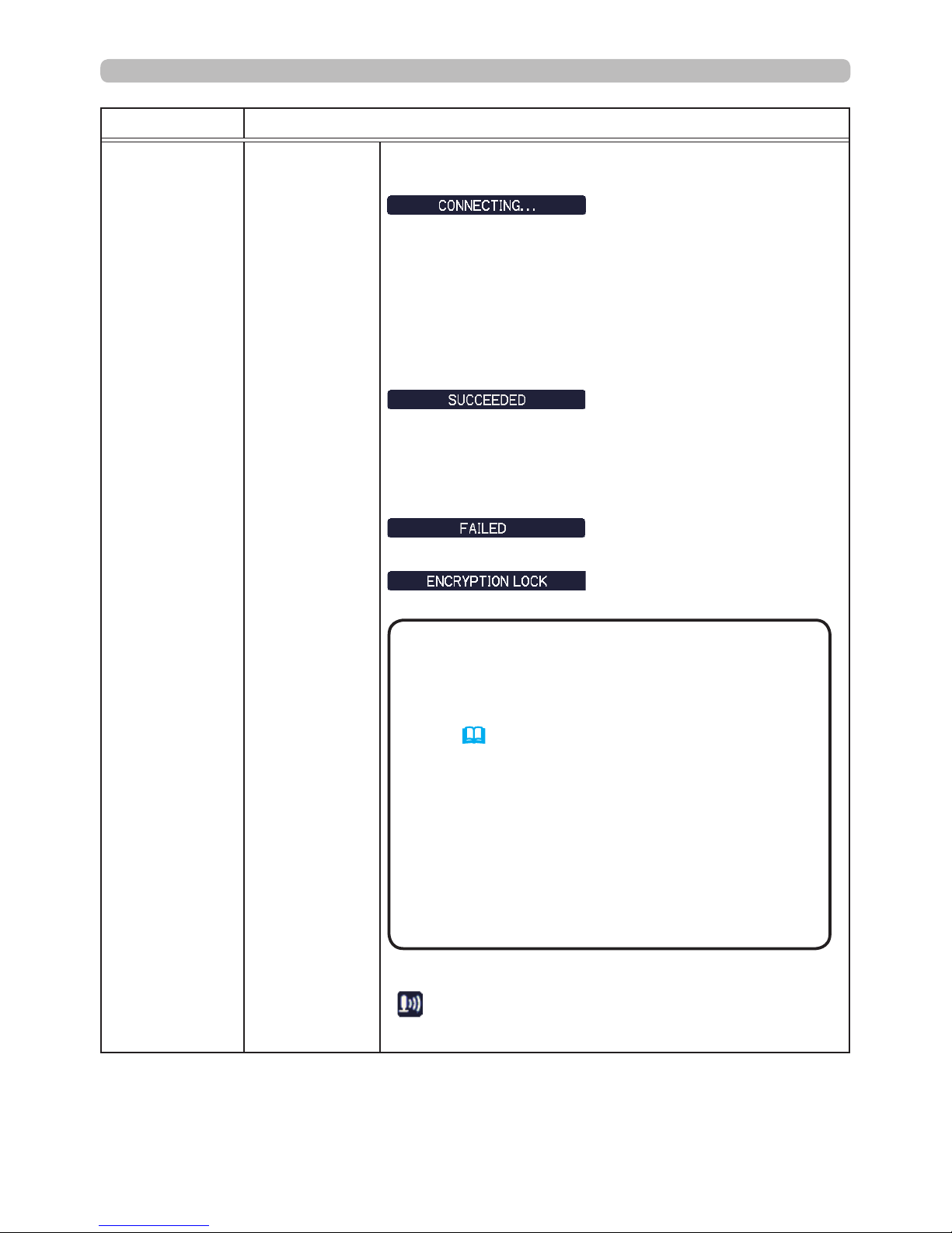
The OSD below is displayed while the
connection is in progress.
The keys other than Reset button are not
available while the connection is in progress.
The connection process is interrupted when
pressing the Reset button.
The OSD below is displayed when the connection
process is complete.
:
Connection succeeded
The message below is displayed when the
connection is not established correctly.
:
Connection failed
:
Encryption Lock enabled
(4)
The icon indicating the connection status
(
) is displayed in SSID SCAN LIST when the
connection is complete.
(continued on next page)
2. Connection to the network
・ Encryption settings cannot be
changed when encryption lock is enabled
in Network Settings – Wireless Setup in
Projector Web Control. Refer to Encryption
Lock. (
&42)
• Open System Authentication is used for WEP
encryption, and Shared Key Authentication
is not supported. The authentication with an
access point is succeeded and it is regarded
that the connection is established normally
even when entering illegal encryption key
due to Open System Authentication, but data
cannot actually be transmitted.
NOTE
Page 25
25
Item Description
WIRELESS
SETUP
(continued)
SSID SCAN
LIST
(continued)
This function is not available in SIMPLE ACCESS
POINT mode.
MODE
Switches between SIMPLE ACCESS POINT and
INFRASTRUCTURE.
Select the mode of the network communication
system. Select according to the settings of your
computer.
SIMPLE ACCESS POINT INFRASTRUCTURE
To save the setting, press the ► button.
DHCP
Congures whether IP address is automatically
obtained or not.
Use the ▲/▼ buttons to turn DHCP on/off.
ON OFF
This function is not available in SIMPLE ACCESS
POINT mode.
(continued on next page)
2. Connection to the network
• The setting changed before switching MODE
without selecting "APPLY" is cancelled.
• When switching MODE, it takes 60 seconds to
be able to use wireless LAN. In the meantime,
the operating speed of the projector may be
decreased and NETWORK INFORMATION
may not be displayed correctly.
NOTE
Page 26
26
Item Description
WIRELESS
SETUP
(continued)
IP
ADDRESS
[SIMPLE ACCESS POINT]
Refer to "Connection in Simple Access Point
Mode".
(&15)
[INFRASTRUCTURE]
Congures the IP address when DHCP is disabled.
Enter the IP ADDRESS.
This function can only be used when DHCP is set
to OFF.
SUBNET
MASK
[SIMPLE ACCESS POINT]
This setting is xed to 255.255.255.0.
[INFRASTRUCTURE]
Congures the subnet mask when DHCP is
disabled.
Enter the SUBNET MASK.
This function can only be used when DHCP is set
to OFF.
DEFAULT
GATEWAY
Congures the default gateway when DHCP is
disabled.
Enter the DEFAULT GATEWAY address.
This function can only be used when DHCP is set
to OFF.
This function is not available in SIMPLE ACCESS
POINT mode.
DNS
SERVER
Congures the DNS server address.
Enter the DNS server address.
This function is not available in SIMPLE ACCESS
POINT mode.
(continued on next page)
2. Connection to the network
This setting cannot be obtained automatically.
NOTE
Page 27
27
Item Description
WIRELESS
SETUP
(continued)
SSID
Congures SSID for wireless network.
[SIMPLE ACCESS POINT]
Enter SSID by using software keyboard. Refer
to PROJECTOR NAME (&21) for how to use
software keyboard.
Default setting of SSID in Simple Access Point
mode is [SimpleAccessPoint]. Change default
setting before use not to overlap.
[INFRASTRUCTURE]
Select one of the DEFAULT (#1~#4) and press ►
or ENTER button.
To adjust CUSTOM
Press the ► or ENTER button when the # 5
CUSTOM is selected. The SSID #5 CUSTOM
menu will be appeared.
Enter SSID by using software keyboard. Refer
to PROJECTOR NAME (&21) for how to use
software keyboard.
(continued on next page)
2. Connection to the network
Page 28
28
Item Description
WIRELESS
SETUP
(continued)
SSID
BROADCAST
Congures SSID BROADCAST.
Set this function to OFF when making SSID
of a projector not to be displayed in wireless
connection list of the computer.
ENCRYPTION
Select the encryption method to be used.
WPA2-PSK(AES) WPA2-PSK(TKIP)
OFF WPA-PSK(AES)
WEP 64bitWEP 128bitWPA-PSK(TKIP)
WEP 64bit and WEP 128bit are available only
in INFRASTRUCTURE mode.
It is required to enter the encryption key when
selecting the encryption method other than
OFF and pressing the ► button.
CH
Select the channel of the wireless LAN to be
used while MODE (
&25) is set to SIMPLE
ACCESS POINT.
The channels 1 to 11 are available. To save the
setting, press the ► button.
• The available channels vary depending on a
country.
(continued on next page)
2. Connection to the network
• WPA2-PSK (AES) is recommended for encryption
method of IEEE802.11n. Transmission speed in
IEEE802.11n may be slow when other encryption
method (WEP, WPA-PSK (TKIP), WPA2-PSK
(TKIP)). Change the setting to “AES” if encryption
other than “AES” is set.
• Encryption method not included in the selected
item cannot be available.
NOTE
Page 29
29
Item Description
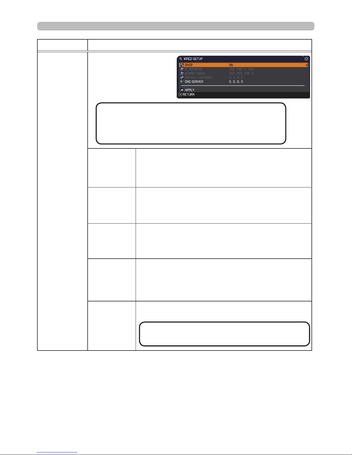
WIRED
SETUP
Congures wired network.
Setting values are saved
after selecting "APPLY".
DHCP
Congures whether IP address is automatically
obtained or not.
Use the ▲/▼ buttons to turn DHCP on/off.
ON OFF
IP
ADDRESS
Congures the IP address when DHCP is disabled.
Enter the IP ADDRESS.
This function can only be used when DHCP is set
to OFF.
SUBNET
MASK
Congures the subnet mask when DHCP is disabled.
Enter the SUBNET MASK.
This function can only be used when DHCP is set
to OFF.
DEFAULT
GATEWAY
Congures the default gateway when DHCP is
disabled.
Enter the DEFAULT GATEWAY address.
This function can only be used when DHCP is set
to OFF.
DNS
SERVER
Congures the DNS server address.
Enter the DNS server address.
(continued on next page)
2. Connection to the network
・Setting values are not saved if Menu dissapears before
selecting "APPLY".
・Be sure to execute
"APPLY" after changing the settings.
NOTE
This setting cannot be obtained automatically.
NOTE
Page 30
30
Item Description
NETWORK
INFORMATION
Selecting this item displays the dialog for viewing the wireless and
wired LAN settings. Use the ▲/▼ buttons to switch the page.
The rst page shows the wireless LAN settings. The second page
is for the wired LAN settings, and the third page is for common
setting item.
WIRELESS
INFORMATION
The following information is displayed.
・
PASSCODE
・
MODE
・
IP ADDRESS
・
SUBNET MASK
・
DEFAULT GATEWAY
・
DNS SERVER
・
MAC ADDRESS
・
SSID
・
SSID BROADCAST
・
ENCRYPTION
・
CH
・
SPEED
Passcord supports the connection between the
projector and the computer when using Network
Presentation. Refer to Network Presentation (&77)
for the details.
(continued on next page)
2. Connection to the network
• IP ADDRESS, SUBNET MASK and
DEFAULT GATEWAY indicate “0.0.0.0” in the
following condition.
(1) The USB wireless adapter is not inserted
into the projector.
(2) DHCP is ON and the projector does not get
address from DHCP server.
•
Nothing (blank) is shown in the CH and SPEED
elds if the USB wireless adapter is not inserted.
NOTE
Page 31
31
2. Connection to the network
• IP ADDRESS, SUBNET MASK and
DEFAULT GATEWAY indicate “0.0.0.0” when
DHCP is ON and the projector has not gotten
address from DHCP server.
NOTE
Item Description
NETWORK
INFORMATION
(continued)
WIRED
INFORMATION
The following information is displayed.
・
PASSCODE
・
IP ADDRESS
・
SUBNET MASK
・
DEFAULT GATEWAY
・
DNS SERVER
・
MAC ADDRESS
Passcord enables the projector and the computer
to be connected to the network easily when
using Network Presentation. Refer to Network
Presentation (
&77) for details.
OTHER
INFORMATION
The following information is displayed.
・
PROJECTOR NAME
・
DATE AND TIME
・
SNTP SERVER
・
TIME DIFFERENCE
• PROJECTOR NAME and SNTP SERVER may
appear truncated if they are too long.
(continued on next page)
Page 32
32
2. Connection to the network
Item Description
SNTP
SETUP
SNTP
SERVER
When you get the time via the network, specify
SNTP server with IP address or domain name.
Up to 255 characters can be entered for domain
name.
They are entered by using software keyboard.
Refer to PROJECTOR NAME(
&21) for how to use
software keyboard.
TIME
DIFFERENCE
Enter the time difference.
Set the same time difference as the one set on
your computer. If unsure, consult your network
administrator.
Use the ► button to return to the menu after
setting the TIME DIFFERENCE.
(continued on next page)
Set the time difference when using SNTP.
NOTE
Page 33
33
2. Connection to the network
Item Description
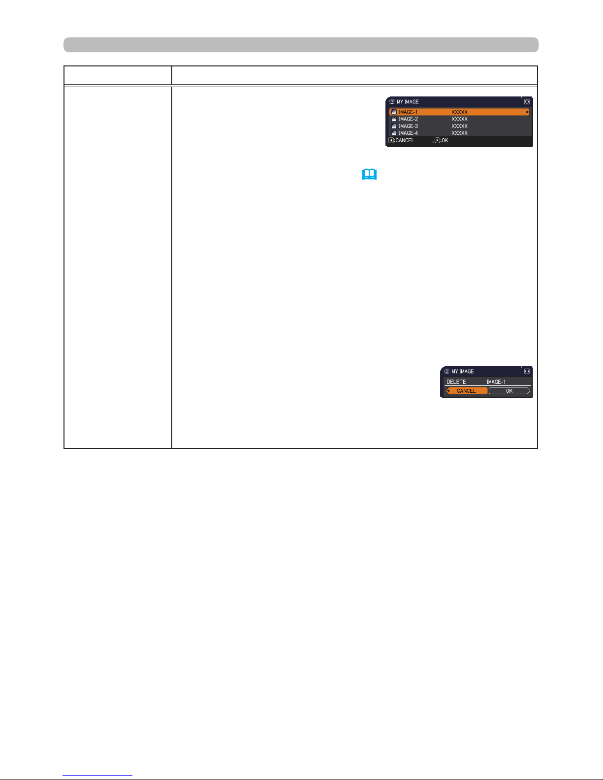
MY IMAGE
Selecting this item displays the MY
IMAGE menu.
Use the application to transfer the
image data. It can be downloaded
from the web site.
Refer to 5. My Image Function (
&81) for the details of MY
IMAGE.
Select an item of still image by the MY IMAGE and the ► or
ENTER button to display the image.
• The item without stored image cannot be selected.
• Each image name is displayed in 16 characters or less.
To switch the image displayed
Use the ▲/▼ buttons.
To return to the menu
Press the ◄ button on the remote control.
To erase the displayed image and its source le in the
projector.
(1) Press the RESET button on the
remote control while displaying an
image to display the MY IMAGE
DELETE menu.
(2) Press the ► button to erase.
To stop erasing, press the ◄ button.
(continued on next page)
Page 34
34
2. Connection to the network
Item Description
EXTERNAL
CONTROL
AMX D.D.
(AMX Device
Discovery)
Use the ▲/▼ buttons to turn the AMX Device
Discovery on/off.
ON OFF
When ON is selected, the projector can be
detected by controllers of AMX connected
to the same network. For the details of AMX
Device Discovery, visit the AMX web site.
URL: http://www.amx.com/
CRESTRON
Use the ▲/▼ buttons to turn the
Crestron
ConnectedTM on/off.
ON OFF
When ON is selected, controlling and
managing the projector can be performed by
using the controllers of Crestron connected
to the same network. For the details of
Crestron Connected
TM
, visit the following
web site.
URL: http://www.crestron.com/
EXTRON
Use the ▲/▼ buttons to turn the
Extron
on/
off.
ON OFF
When ON is selected, the controllers of
Extron connected via HDBaseT
TM
can detect
the projector. For the details of Extron, visit
the following web site.
URL: http://www.exrtron.com/
(continued on next page)
• This item is enabled
only when HDBaseT is selected in
WIRED NETWORK.
NOTE
Page 35

35
2. Connection to the network
Item Description
PRESENTATION
To use Network Presentation, an exclusive application is
required.
You can also download the latest version and relevant
information from the Hitachi website.
Refer to 4. Network Presentation (
&77) for the details of
Network Presentation.
QUIT
PRESENTER
MODE
If you set a computer to the Presenter mode while
its image is projected, the projector is occupied by
the computer and access from any other computer is
blocked.
Use this function to quit the Presenter mode and
allow other computers to access the projector.
Select this item to display a dialog.
Press the ► button to choose OK in the dialog.
The Presenter mode is cancelled and a message is
displayed indicating the result.
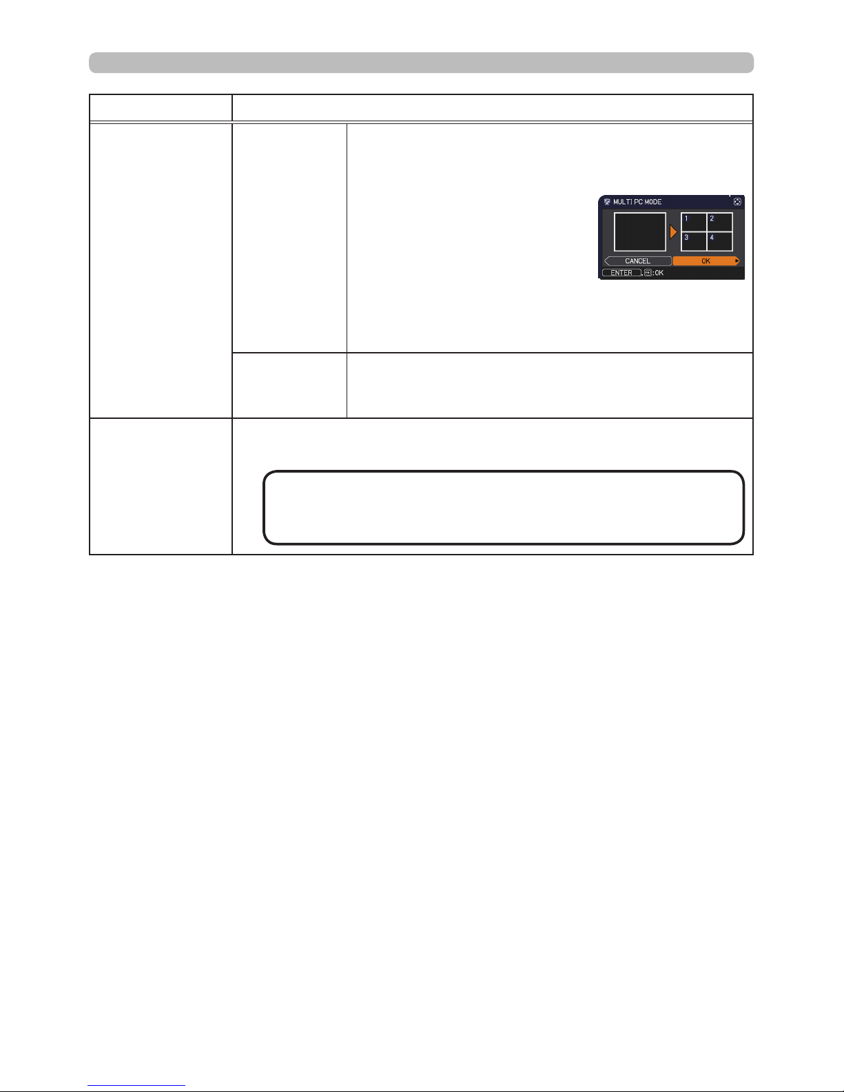
MULTI PC
MODE
If you set one or more computers to the Multi PC
mode and send their images to the projector, you can
select the display mode on the projector from two
options below.
- Single PC mode: displays the image of the selected
computer on full screen.
- Multi PC mode: displays the images sent from up to
four computers on screen that is divided into quarter
sections.
Select this item to display a dialog.
Use the dialog to change the display mode as
explained below.
• To change from Multi PC mode to Single PC mode,
select one of computers in the dialog using the
▲/▼/◄/► buttons and press the ENTER or INPUT
button.
Press the ► button to choose OK, and then press
ENTER or INPUT again. The image for the selected
computer is displayed on full screen.
(continued on next page)
(continued on next page)
Page 36
36
Item Description
PRESENTATION
(continued)
MULTI PC
MODE
(continued)
• To change from Single PC mode to Multi PC
mode, press the ► button to choose OK in the
dialog and press the ENTER or INPUT button.
The display mode is changed.
• The Presenter mode setting
of the selected computer
becomes valid when the
display mode is changed to
Single PC mode. Also, the
Presenter mode setting becomes invalid when
the display mode is changed to Multi PC mode,
regardless of the setting on the computers.
DISPLAY
USER NAME
Selecting this item displays the user name. This
function helps you identify from which computer
the current image is sent.
WIRED
NETWORK
Selects whether to use LAN or HDBaseTTM port.
LAN HDBaseT
2. Connection to the network
Only either LAN or HDBaseT port can be used for the connection
to the network. Switch it according to the environment.
NOTE
Page 37

37
You can adjust or control the projector via a network from a web browser on a
computer connected to the same network.
■Projector Web Control
You can control the projector, collect
the status such as lamp time, and set
e-mail or schedule, etc. in Projector
Web Control.
Recommended web browser
・ Internet Explorer
®
8/ 9/ 10/ 11
• Web browsers other than recommended ones may not work.
• If JavaScript® is disabled in your web browser conguration, you must enable
JavaScript® in order to use the projector web pages properly. See the Help les
for your web browser for details on how to enable JavaScript®.
• It is recommended that all web browser updates are installed.
• If data is transferred via wireless and wired LAN at the same time, the
projector may not process the data correctly.
NOTE
3. Web Control
3. Web Control
(continued on next page)
■Crestron e-Control
Crestron e-Control
®
is a control
interface using a web browser provided
by Crestron Electronics, Inc..
Crestron e-Control
®
can control and
monitor the projector.
Page 38
38
• Crestron e-Control® is created using Flash®. You need to install
Adobe® Flash® Player on your computer to use Crestron e-Control®. Crestron
e-Control® is not displayed in a web browser that does not support Flash®.
• In any of the following cases, the selection window does not appear but the
Login window of the Projector Web Control is displayed.
- Network Settings - Other Setup - Crestron e-Control is "Disable" (&45)
- Network Settings - Common Setup - Crestron is "OFF" (&42)
- NETWORK menu - EXTERNAL CONTROL - CRESTRON is "OFF" (&34)
NOTE
3. Web Control
Refer to the following for conguring or controlling the projector via a web browser.
Make sure that your computer and the projector is connected via network, and
then start Web browser.
Enter the projector's IP address into URL input box of the Web browser as the
example below, and then press the Enter key or button.
Example: If the IP address of the projector is set to 192.168.1.10:
Enter “http://192.168.1.10/” into the address bar of the web browser
and press the Enter key or click
button.
If a correct URL is input, and the
projector and your computer are
connected to the same network
correctly, the selection window will be
displayed.
• Do not control the projector with the projector's menu or remote
control, and via Web Control at the same time. It may cause some operational
errors in the projector.
• The language used on the Projector Web Control is the same as that of the
OSD on the projector. If you want to change it, you need to change the OSD
language on the projector. (&SCREEN menu in the Operating Guide)
NOTE
Page 39

39
3. Web Control
3.1.1 Login
To use the Projector Web Control function, you need
to login with your user name and password.
Below are the factory default settings for user
name and password.
User name Administrator
Password <blank>
Enter your user name and password, and then click the [OK].
If you login successfully, the screen below will be displayed.
Main menu
Click the desired operation or conguration item on the main menu.
3.1 Projector Web Control
Login window
Page 40

40
3.1.2 Network Information
Displays the projector’s current network
conguration settings.
Item Description
Common Information
Displays information common to both wireless and wired LAN.
Projector Name Displays the projector name settings.
Wireless Information Displays the current settings of wireless LAN.
Mode Displays the mode of wireless LAN communication.
DHCP Displays the DHCP setting.
IP Address Displays the IP address.
Subnet Mask Displays the subnet mask.
Default Gateway Displays the default gateway.
DNS Server Address Displays the DNS server address.
MAC Address Displays the MAC address.
SSID Displays the SSID used by the projector.
SSID Broadcast Displays the SSID Broadcast used by the projector.
Encryption Displays the data encryption setting.
Ch Displays the channel used for wireless LAN.
Speed Displays the current wireless LAN transmission speed.
Wired Information Displays the current wired LAN settings.
DHCP Displays the DHCP setting.
IP Address Displays the IP address.
Subnet Mask Displays the subnet mask.
Default Gateway Displays the default gateway.
DNS Server Address Displays the DNS server address.
MAC Address Displays the MAC address.
3. Web Control
3.1 Projector Web Control (continued)
Page 41

41
3.1.3 Network Settings
Displays and congures network settings.
Item Description
Common Setup
Congures the settings common to wireless and wired LAN.
Projector Name
Congures the name of the projector.
The length of the Projector Name can be up to 64
alphanumeric characters. Only alphabets, numbers and
following symbols can be used.
!"#$%&'()*+,-./:;<=>?@[\]^_`{|}~ and space.
Particular projector name is pre-assigned by default.
sysLocation (SNMP)
Congures the location to be referred to when using SNMP.
The length of the sysLocation can be up to 255 alphanumeric
characters. Only numbers ‘0-9’, alphabet ‘a-z’ and ‘A-Z’ can
be used.
sysContact (SNMP)
Congures the contact information to be referred to when
using SNMP.
The length of the sysContact can be up to 255 alphanumeric
characters. Only numbers ‘0-9’, alphabet ‘a-z’ and ‘A-Z’ can
be used.
AMX D.D.
(AMX Device
Discovery)
Congures the AMX Device Discovery setting to detect the
projector from the controllers of AMX connected to the same
network. For the details of AMX Device Discovery, visit the
AMX web site.
URL: http://www.amx.com
(continued on next page)
3. Web Control
3.1 Projector Web Control (continued)
Page 42
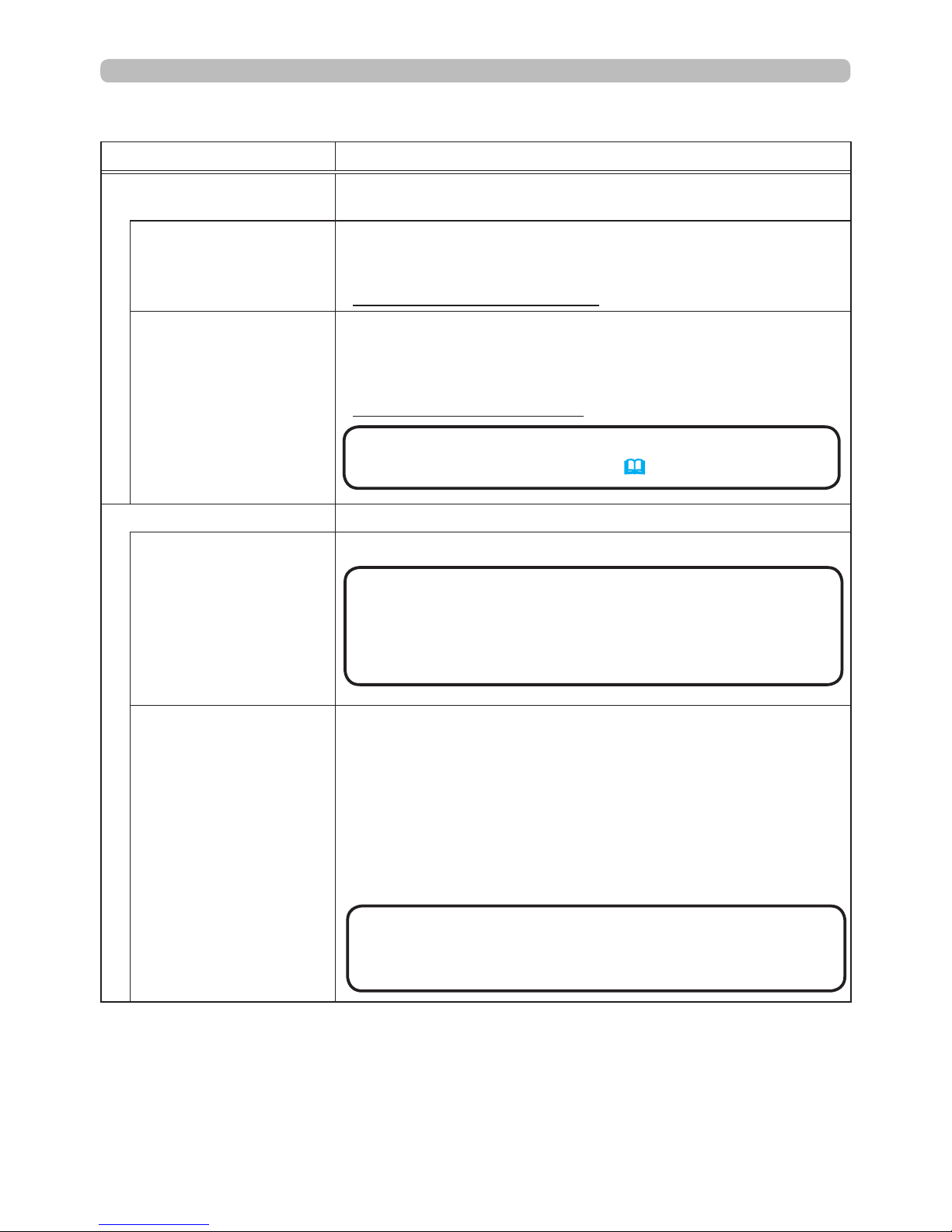
42
3.1 Projector Web Control - Network Settings (continued)
3. Web Control
• When switching MODE, it takes 60 seconds
to be able to use wireless LAN. In the meantime, the
operating speed of the projector may be decreased
and NETWORK INFORMATION may not be displayed
correctly.
NOTE
• If Encryption Lock is ON, wireless connection
is performed only when it can be connected without
changing the current settings.
NOTE
Item Description
Common Setup
(continued)
Congures the settings common to wireless and wired LAN.
Crestron
Congures the Crestron setting to detect the projector from
the controllers of Crestron connected to the same network.
For the details of Crestron, visit the Crestron web site.
URL: http://www.crestron.com
Extron
Congures the Extron setting to detect the projector from
the controllers of Extron connected to the same network via
HDBaseT
TM
port. For the details of Extron, visit the Extron
web site.
URL: http://www.extron.com
Wireless Setup Congures the wireless LAN settings.
Mode
Select "Simple Access Point" or "Infrastructure".
Encryption Lock
Permits or inhibits changes of the following settings related to
wireless connection.
・
Mode
・
SSID
・
SSID Broadcast
・
Encryption
・
Encryption key (WEP key, WPA passphrase)
When Encryption Lock is set to ON, these settings cannot be
changed by the menu of the projector.
(continued on next page)
• This item is enabled only when HDBaseT is
selected in WIRED NETWORK. (
&36)
NOTE
Page 43
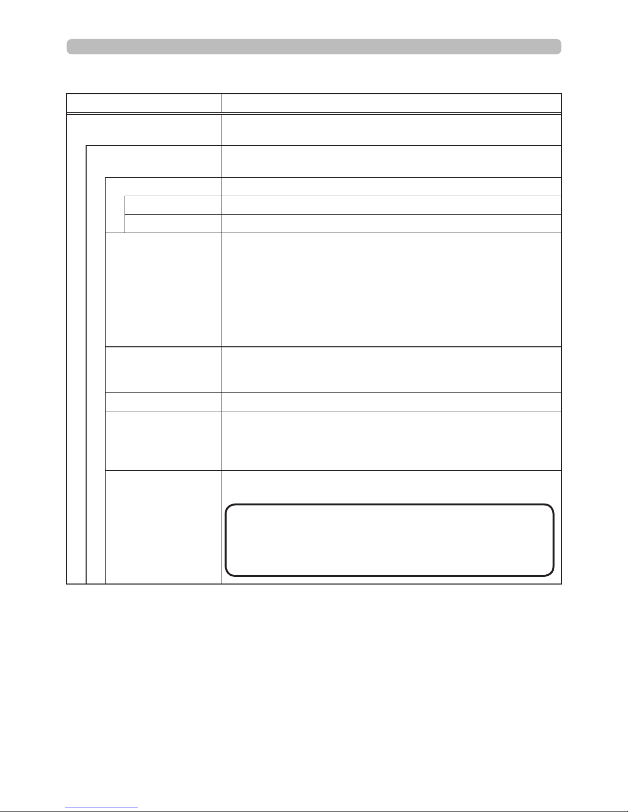
43
3.1 Projector Web Control - Network Settings (continued)
3. Web Control
Item Description
Wireless Setup
(continued)
Congures the wireless LAN settings.
Simple Access Point
settings
Congures Simple Access Point mode.
IP Conguration Congures network settings.
IP Address Congures the IP address.
Subnet Mask Subnet mask of the projector is xed to 255.255.255.0.
SSID
Input SSID.
The maximum number of input characters is 32.
Only alphabets, numbers and the following symbols can be
used.
!"#$%&'()*+,-./:;<=>?@[\]^_`{|}~ and space.
Default setting of SSID in Simple Access Point mode is
[SimpleAccessPoint].
Change default setting before use not to overlap.
SSID Broadcast
Select SSID Broadcast.
Set this function to OFF when making SSID of a projector not
to be displayed in wireless connection list of the computer.
Encryption Select data encryption method.
WPA Passphrase
Input WPA Passphrase.
Available number of input characters is 8 to 63. Only
alphabets, numbers and the following symbols can be used.
!"#$%&'()*+,-./:;<=>?@ [\]^_`{|}~ and space
Ch
Select from “1” to “11”, a channel to use in the Simple Access
Point mode.
(continued on next page)
• The channels may vary depending on the
country. In addition, depending on the country or region,
it may be required to use a wireless network card that
conforms to the standards in the respective country or
region.
NOTE
Page 44

44
3.1 Projector Web Control - Network Settings (continued)
3. Web Control
Item Description
Wireless Setup
(continued)
Congures the wireless LAN settings.
Infrastructure
settings
Congures Infrastructure mode.
IP Conguration Congures network settings.
DHCP ON Enables DHCP.
DHCP OFF Disables DHCP.
IP Address Congures the IP address when DHCP is disabled.
Subnet
Mask
Congures the subnet mask when DHCP is disabled.
Default
Gateway
Congures the default gateway when DHCP is disabled.
DNS Server
Address
Congures the DNS server address.
SSID
Select an SSID from the list.
If you require to set your unique SSID, select [Custom], then
set your own SSID following the rules below.
The maximum number of input characters is 32.
Only alphabets, numbers and the following symbols can be
used.
!"#$%&'()*+,-./:;<=>?@[\]^_`{|}~ and space.
Encryption Select data encryption method.
WEP Key
Input the WEP key.
Either ASCII characters or hexadecimal numbers can be
used during WEP key input. However, you cannot use a
combination of both.The length of the key is dened as
follows according to the WEP and character formats.
Encryption ASCII characters HEX numbers
WEP 64bit 5 characters 10 characters
WEP 128bit 13 characters 26 characters
WPA Passphrase
Input WPA Passphrase.
Available number of input characters is 8 to 63. Only
alphabets, numbers and the following symbols can be used.
!"#$%&'()*+,-./:;<=>?@ [\]^_`{|}~ and space
(continued on next page)
Page 45
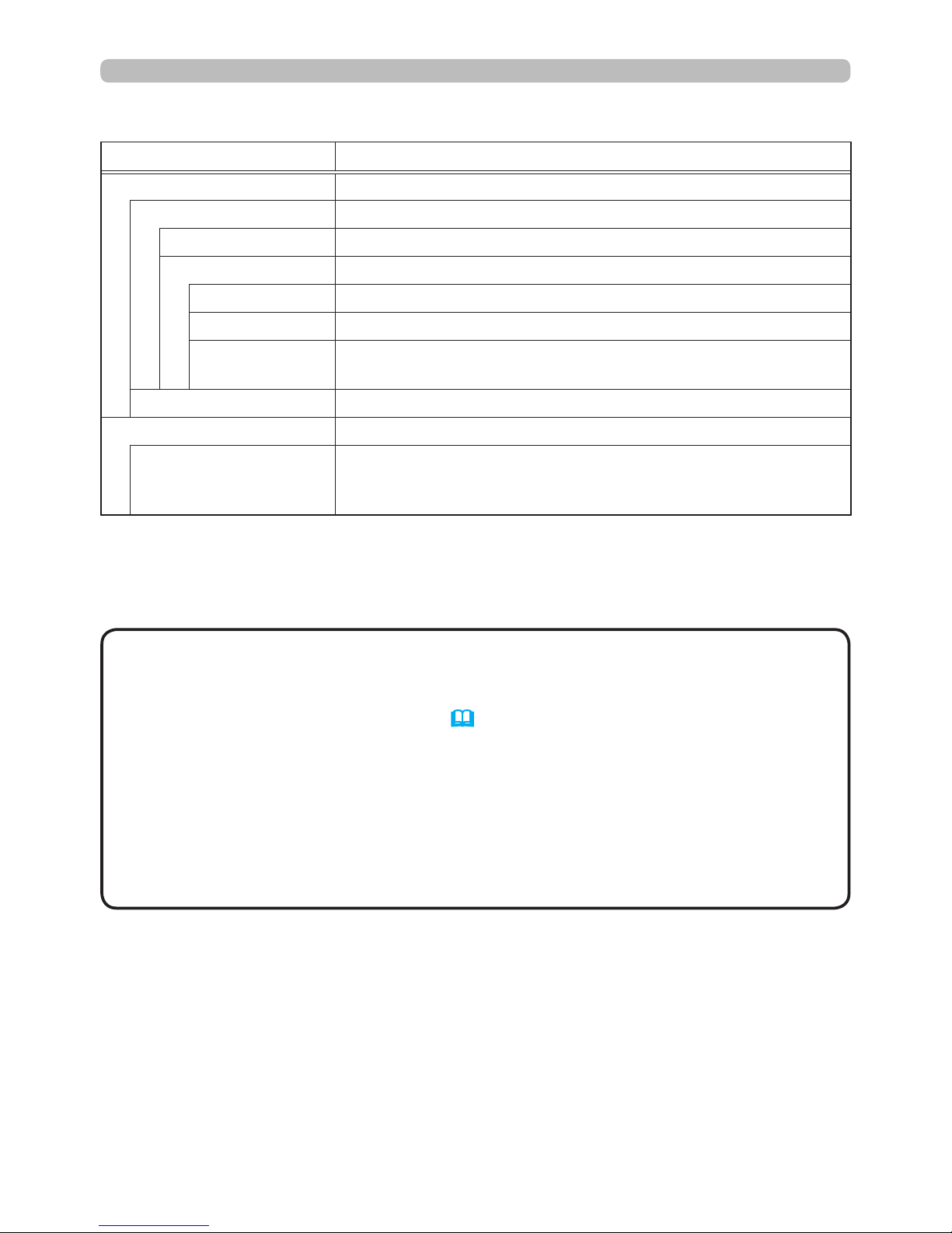
45
Click the [Apply] button to save the settings.
3.1 Projector Web Control - Network Settings (continued)
Item Description
Wired Setup Congures the wired LAN settings.
IP Conguration Congures network settings.
DHCP ON Enables DHCP.
DHCP OFF Disables DHCP.
IP Address Congures the IP address when DHCP is disabled.
Subnet Mask Congures the subnet mask when DHCP is disabled.
Default
Gateway
Congures the default gateway when DHCP is disabled.
DNS Server Address Congures the DNS server address.
Other Setup Congures other network settings.
Crestron e-Control
Set whether or not to use Crestron e-Control
®
.
If you choose Disable, not the selection window but the Login
window of Projector Web Control will be displayed at rst.
3. Web Control
• The new conguration settings are activated after restarting the
network connection. When the conguration settings are changed, you must
restart the network connection. You can restart the network connection from
Network Restart on the main menu. (&66)
• If you connect the projector to an existing network, consult a network
administrator before setting server addresses.
• The WEP Key, WPA passphrase and SSID settings will not be set if the invalid
characters are used.
• The projector does not allow both wireless and wired LAN to be connected to
the same network. Do not set the same network address for both wireless and
wired LAN.
NOTE
Page 46

46
3.1.4 Port Settings
Displays and congures communication port
settings.
Item Description
Network Control Port1
(Port:23)
Congures command control port 1 (Port:23).
Port open Click the [Enable] check box to use port 23.
Authentication
Click the [Enable] check box when authentication is required
for this port.
Network Control Port2
(Port:9715)
Congures command control port 2 (Port:9715).
Port open Click the [Enable] check box to use port 9715.
Authentication
Click the [Enable] check box when authentication is required
for this port.
PJLinkTM Port
(Port:4352)
Congures the PJLink
TM
port (Port:4352).
Port open Click the [Enable] check box to use port 4352.
Authentication
Click the [Enable] check box when authentication is required
for this port.
My Image Port
(Port:9716)
Congures the My Image Port (Port:9716).
Port open Click the [Enable] check box to use port 9716.
Authentication
Click the [Enable] check box when authentication is required
for this port.
Messenger Port
(Port:9719)
Congures the Messenger Port (Port:9719).
Port open Click the [Enable] check box to use port 9719.
Authentication
Click the [Enable] check box when authentication is required
for this port.
(continued on next page)
3. Web Control
3.1 Projector Web Control (continued)
Page 47
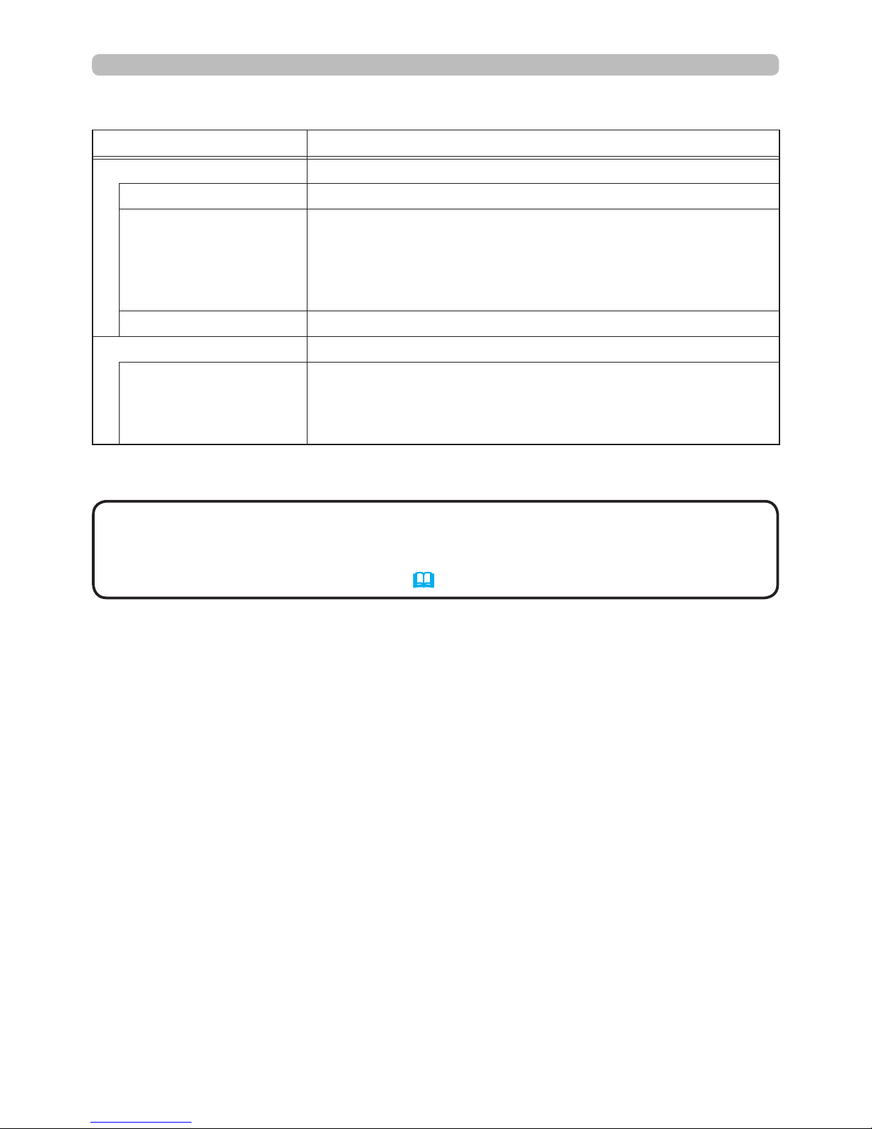
47
Item Description
SNMP Port Congures the mib le port.
Port open Click the [Enable] check box to use SNMP.
Trap address
Congures the destination of the SNMP Trap in IP format.
• The address allows not only IP address but also domain
name if the valid DNS server is setup in the Network
Settings. The maximum length of host or domain name is up
to 255 characters.
Download MIB le Downloads a MIB le from the projector.
Network Bridge Port Congures the Bridge port number.
Port number
Input the port number.
Except for 41794, 9715, 9716, 9719, 9720, 5900, 5500, 4352
between 1024 and 65535 can be set up. It is set to 9717 as
the default setting.
Click the [Apply] button to save the settings.
3.1 Projector Web Control - Port Settings (continued)
• The new conguration settings are activated after restarting the
network connection. When the conguration settings are changed, you must
restart the network connection. You can restart the network connection from
Network Restart on the main menu. (&66)
NOTE
3. Web Control
Page 48

48
3.1.5 Mail Settings
Displays and congures e-mail addressing
settings.
Item Description
Send Mail
Click the [Enable] check box to use the e-mail function. Congure the
conditions for sending e-mail under the Alert Settings.
Authentication
Selects the authenticaton method.
Enter the user name of the SMTP server or POP server as the user
name.
Enter the password of the SMTP server or POP server as the
password.
The maximum number of input characters is 63.
Only alphabets, numbers and the following symbols can be used.
!"#$%&'()*+,-./:;<=>?@[\]^_`{|}~ and space.
SMTP Server Congures the SMTP server.
Server
address
Congures the SMTP server address.
• The address allows not only IP address but also domain name if the
valid DNS server is setup in the Network Settings. The maximum
length of host or domain name is up to 255 characters.
Alphanumeric characters, "-", or "." can be used.
Port
number
Congures the port number of the SMTP server.
It is set to 25 as the default setting.
POP Server Congures the POP server.
Server
address
Congures the POP server address.
• The address allows not only IP address but also domain name if the
valid DNS server is setup in the Network Settings. The maximum
length of host or domain name is up to 255 characters.
Alphanumeric characters, "-", or "." can be used.
Port
number
Congures the port number of the POP server.
It is set to 110 as the default setting.
(continued on next page)
3. Web Control
3.1 Projector Web Control (continued)
Page 49
49
3.1 Projector Web Control - Mail Settings (continued)
3. Web Control
Item Description
Sender E-mail address
Congures the sender e-mail address.
The length of the sender e-mail address can be up to 255
alphanumeric characters.
Recipient E-mail address
Congures the e-mail address of up to ve recipients. You
can also specify the [to] or [cc] for each address. The
length of the recipient e-mail address can be up to 255
alphanumeric characters.
Send Test Mail Sends a test e-mail to the set address.
Click the [Apply] button to save the settings.
Mail settings are initialized when clicking the [Reset] button.
• You can conrm whether the mail settings work correctly by using the
[Send Test Mail] button. Enable Send Mail setting before clicking the [Send
Test Mail].
• If you connect the projector to an existing network, consult a network
administrator before setting server addresses.
NOTE
Page 50

50
3.1.6 Alert Settings
Displays and congures failure & alert settings.
Notication such as e-mail and SNMP trap can be set regarding the following
errors/warnings.
・Cover Error
・Fan Error
・Lamp Error
・Temp Error
・Air Flow Error
・Cold Error
・Filter Error
・Shade Error
・Lens Shift Error
・AC Blackout Error
・Other Error
・Schedule Execution Error
・Lamp Time Alarm
・Filter Time Alarm
・Filter Status Notication
・Transition Detector Alarm
・Cold Start
・Authentication Failure
Refer to Chapter 8-1 for the details of the above errors/warnings. (
&
89)
3. Web Control
3.1 Projector Web Control (continued)
Page 51

51
The Alert Items are shown below.
Click the [Apply] button to save the settings.
The settings are initialized when clicking the [Reset] button.
3.1 Projector Web Control - Alert Settings (continued)
3. Web Control
Item Description
Alarm Time
Congures the time to alert.
(Only Lamp Time Alarm and Filter Time Alarm.)
SNMP Trap Click the [Enable] check box to enable SNMP Trap alerts.
Send Mail
Click the [Enable] check box to enable e-mail alerts.
(Except Cold Start and Authentication Failure.)
Mail Subject
Congures the subject line of the e-mail to be sent.
The length of the subject line can be up to 100 alphanumeric
characters. Using any other character may shorten the
subject line.
(Except Cold Start and Authentication Failure.)
Mail Text
Congures the text of the e-mail to be sent.
The length of the text is up to 1024 alphanumeric characters.
Using any other character may shorten the text.
(Except Cold Start and Authentication Failure.)
Page 52
52
3.1.7 Schedule Settings
Displays and congures schedule settings.
3. Web Control
3.1 Projector Web Control (continued)
• Be sure to set the date and time
before enabling scheduled events. (&56)
• Refer to 8.3 Event Scheduling for the details
of schedule settings. (&94)
NOTE
1) Schedule Management
Item Description
Sunday
Schedule settings executed on each day of the week.
Monday
Tuesday
Wednesday
Thursday
Friday
Saturday
Specic date No.1
Schedule settings executed on specied day. Up to 10 days
can be specied.
Specic date No.2
Specic date No.3
Specic date No.4
Specic date No.5
Specic date No.6
Specic date No.7
Specic date No.8
Specic date No.9
Specic date No.10
Page 53
53
Item Description
Schedule
Select the checkbox of the schedule to execute.
Program
Select the program. The detail of the event registered in each
program can be conrmed in the program list displayed at
the bottom of the screen.
Date (Month/Day)
Input the date (month/day) when the schedule is executed for
Specic date 1~10.
Click the [Apply] button to save the settings.
Click the [Refresh] button to update the screen to the latest status.
Click the [Program Edit] button to display the program edit of the selected
program.
Click the [Copy to] button to copy the content of the program from which you
copy (the list on the left) to the program to which you copy (the list on the right).
The same program No. cannot be selected for both the program from which and
the program to which you copy.
3. Web Control
3.1 Projector Web Control - Schedule Settings (continued)
Page 54
54
3.1 Projector Web Control - Schedule Settings (continued)
Item Description
Time Congures the time to execute events.
Event [Parameter] Congures the events to be executed.
Power
Congures the parameters for power control.STANDBY
ON
Input Source
Congures the parameters for switching input.
COMPUTER IN
HDMI 1
HDMI 2
DisplayPort
HDBaseT
SDI
(:8)
VIDEO
LAN
My Image
Congures the parameters for My Image data display.
IMAGE-OFF
IMAGE-1
IMAGE-2
IMAGE-3
IMAGE-4
3. Web Control
The current event settings are displayed on the
list. To add additional functions and events, set
the following items.
2) Program Edit
• A maximum of 16 programs of
schedule can be set. A maximum of 20 events
can be registered in 1 program.
NOTE
Page 55

55
3.1 Projector Web Control - Schedule Settings (continued)
Item Description
Messenger
Congures the parameters for Messenger data display.
TEXT-OFF
TEXT-1
TEXT-2
TEXT-3
TEXT-4
TEXT-5
TEXT-6
TEXT-7
TEXT-8
TEXT-9
TEXT-10
TEXT-11
TEXT-12
Eco Mode
Congures the parameters for eco mode switching.NORMAL
ECO
Blank
Congures the parameters for blank screen on/off control.OFF
ON
Click the [Register] button to add new events to the program.
Click the [Delete] button to delete events from the program.
Click the [Delete All] button to clear all the events registered in the current
selected program.
Click the [Back] button to go back to the schedule management screen.
3. Web Control
Page 56

56
3.1.8 Date/Time Settings
Displays and congures the date and time
settings.
Item Description
Current Date Congures the current date in year/month/day format.
Current Time Congures the current time in hour:minute:second format.
Daylight Savings Time
Click the [ON] check box to enable daylight savings time and
set the following items.
Start Congures the date and time daylight savings time begins.
Month Congures the month daylight savings time begins (1~12).
Week
Congures the week of the month daylight savings time
begins (First, 2, 3, 4, Last).
Day
Congures the day of the week daylight savings time begins
(Sun, Mon, Tue, Wed, Thu, Fri, Sat).
Time
hour Congures the hour daylight savings time begins (0 ~ 23).
minute Congures the minute daylight savings time begins (0 ~ 59).
End Congures the date and time daylight savings time ends.
Month Congures the month daylight savings time ends (1 ~ 12).
Week
Congures the week of the month daylight savings time ends
(First, 2, 3, 4, Last).
Day
Congures the day of the week daylight savings time ends
(Sun, Mon, Tue, Wed, Thu, Fri, Sat).
Time
hour Congures the hour daylight savings time ends (0 ~ 23).
minute Congures the minute daylight savings time ends (0 ~ 59).
(continued on next page)
3. Web Control
3.1 Projector Web Control (continued)
Page 57
57
Item Description
Time difference
Congures the time difference. Set the same time difference
as the one set on your computer. If unsure, consult your IT
manager.
SNTP
SNTP Server
Address
Congures the SNTP server address in IP format.
• The address allows not only IP address but also domain
name if the valid DNS server is setup in the Network
Settings. The maximum length of host or domain name is
up to 255 characters.
Cycle
Congures the interval at which to retrieve Date and Time
information from the SNTP server (hour:minute).
Click the [Apply] button to save the settings.
• The new conguration settings are activated after restarting the
network connection. When the conguration settings are changed, you must
restart the network connection. You can restart the network connection from
Network Restart on the main menu. (&66)
• If you connect the projector to an existing network, consult a network
administrator before setting server addresses.
• To enable the SNTP function, the time difference must be set.
• The projector will retrieve Date and Time information from the time server and
override time settings when SNTP is enabled.
•
The internal clock’s time may not remain accurate. Using SNTP is recommended
to maintain accurate time.
• The internal battery is required to be replaced when the time is off soon after
setting date and time.
NOTE
3.1 Projector Web Control - Date/Time Settings (continued)
3. Web Control
Page 58

58
3.1.9 Security Settings
Displays and congures passwords and other
security settings.
Item Description
User Account Congures the user name and password.
User name
Congures the user name.
The length of the text can be up to 32 alphanumeric
characters.
Password
Congures the password.
The length of the text can be up to 255 alphanumeric
characters.
Re-enter Password Reenter the above password for verication.
Network Control
Congures the Authentication password for Network Control
Port1 (Port: 23), Network Control Port2 (Port: 9715),
PJLink™ Port (Port: 4352), My Image Port (Port: 9716), and
Messenger Port (Port: 9719). (
&46)
Authentication
Password
Congures the Authentication password.
The length of the text can be up to 32 alphanumeric
characters.
Re-enter
Authentication
Password
Reenter the above password for verication.
Network Presentation
Setting an authentication password used in Network
Presentation.The authentication function is disabled when an
authentication password is not set.
Authentication
Password
Congures the Authentication password.
The length of the text can be up to 15 alphanumeric
characters.
Re-enter
Authentication
Password
Reenter the above password for verication.
(continued on next page)
3. Web Control
3.1 Projector Web Control (continued)
Page 59
59
3. Web Control
3.1 Projector Web Control - Security Settings (continued)
• The new conguration settings are activated after restarting the
network connection. When the conguration settings are changed, you must
restart the network connection. You can restart the network connection from
Network Restart on the main menu. (&66)
• Only numbers ‘0-9’, alphabet ‘a-z’ and ‘A-Z’ can be used.
NOTE
Item Description
SNMP Congures the community name if SNMP is used.
Community name
Congures the community name. The length of the text can
be up to 64 alphanumeric characters.
Click the [Apply] button to save the settings.
Page 60
60
3.1.10 Projector Control
Operations of the projector can be performed
with the items on the screen.
The categories of the items are shown in the
main menu. Most of the items have a submenu.
Refer to the table below for details.
• The setting value may not match with the actual value if the user
changes the value manually. In that case, refresh the page by clicking the
[Refresh] button.
NOTE
Item
MAIN
POWER
INPUT SOURCE
BLANK ON/OFF
MUTE
FREEZE
MAGNIFY
MAGNIFY POSITION V
MAGNIFY POSITION H
TEMPLATE
SHADE
[ON]: closed / [OFF]: opened
ZOOM
/ : Turns the lens to the upper or lower limit of its movable range.
: Stops turning the lens.
/ / / : Fine adjustment in two steps is available.
FOCUS
/ : Turns the lens to the upper or lower limit of its movable range.
: Stops turning the lens.
/ / / : Fine adjustment in two steps is available.
LENS SHIFT V
LENS SHIFT H
/ : Turns the lens to the upper or lower limit of its movable range.
: Stops turning the lens.
/ / / :
Vertical and horizontal ne adjustment in two steps is available.
(continued on next page)
3. Web Control
3.1 Projector Web Control (continued)
Page 61

61
3. Web Control
3.1 Projector Web Control - Projector Control (continued)
Item
MAIN
(continued)
LENS MEMORY
WINDOW CONFIGURATION - OFF / PbyP / PinP
Click the [Apply] button to execute after selecting the display mode (OFF/
PbyP/ PinP) from the dropdown list. Click the [Edit] button to display the
screen for detailed settings while PbyP or PinP display mode.
MY IMAGE
MY IMAGE DELETE
PICTURE
PICTURE QUALITY
PICTURE MODE
GAMMA
COLOR TEMP
ACCENTUALIZER
HDCR
COLOR MANAGEMENT
BRIGHTNESS
CONTRAST
COLOR
TINT
SHARPNESS
ACTIVE IRIS
MY MEMORY
IMAGE
ASPECT
The selected parameter cannot be set depending on the input signal.
OVER SCAN
V POSITION
H POSITION
H PHASE
H SIZE
AUTO ADJUST EXECUTE
INPUT
PROGRESSIVE
VIDEO NR
COLOR SPACE
VIDEO FORMAT
DIGITAL FORMAT
DIGITAL RANGE
COMPUTER IN
FRAME LOCK
(continued on next page)
Page 62
62
3. Web Control
3.1 Projector Web Control - Projector Control (continued)
Item
SETUP
KEYSTONE
KEYSTONE V
KEYSTONE H
PERFECT FIT SETUP - Corner Position/Line Distortion
WARPING MODE
EDGE BLENDING
MODE
BLENDING LEVEL
BLENDING REGION
CROPPING
DIMMING LEVEL
WHITE BALANCE GAIN
WHITE BALANCE OFFSET
BLACK LEVEL
LAMP & FILTER
ECO MODE
FILTER MESSAGE
IMAGE OPTIMIZER
PICTURE POSITION
INSTALLATION
STANDBY MODE
OSD MESSAGE
AUDIO
VOLUME
SPEAKER
AUDIO SOURCE
(continued on next page)
• The network function is not available when STANDBY
MODE is set to SAVING and the projector is in standby mode.
Connect the projector to the network after setting STANDBY
MODE to NORMAL.
NOTE
Page 63

63
3. Web Control
3.1 Projector Web Control - Projector Control (continued)
Item
SCREEN
LANGUAGE
Click the [Apply] button to switch the language on the Web screen
according to the setting of the selected language in the projector.
MENU POSITION V
MENU POSITION H
BLANK
AUTO BLANK
START UP
MyScreen Lock
TEMPLATE
C.C. - DISPLAY
C.C. - MODE
C.C. - CHANNEL
OPTION
SOURCE SKIP
AUTO SEARCH
DIRECT POWER ON
AUTO POWER OFF
SHADE TIMER
MY BUTTON – 1 / 2 / 3 / 4
REMOTE RECEIV.
REMOTE FREQ.
REMOTE ID
SERVICE
Quit Presenter Mode
Quit compulsorily from the Presenter mode.
Refer to Chapter 4 for the details of Presenter Mode.
(
&77
)
Page 64
64
3.1.11 Remote Control
The functions on the bundled remote control are assigned to the Web Remote
Control screen.
Do not control the projector with the projector's remote control and via Web Remote
Control at the same time. It may cause some operational errors in the projector.
3. Web Control
3.1 Projector Web Control (continued)
• STANDBY
• ON
• COMPUTER IN
• HDMI 1
• HDMI 2
• DisplayPort
• HDBaseT
• SDI (8980WU only)
• VIDEO
• LAN
• AV MUTE
• FREEZE
• ▲/ ▼/ ◄ / ►
• ENTER
• MENU
• RESET
• One operation can be executed only with one click. The button should
be clicked repeatedly to operate continuously.
• When clicking the button repeatedly, some commands may not be sent
correctly. Click it at intervals.
•
When the [STANDBY] or [ON] button is pushed, a message window comes up to
conrm the operation. To control the power, push [OK], otherwise push [Cancel].
NOTE
:8/::
/
:8
Page 65

65
3.1.12 Projector Status
Displays the current settings and status of the
projector.
Item Description
Error Status Displays the error status.
Lamp Time Displays the usage time for the lamp.
Filter Time Displays the usage time for the lter.
Filter Status Displays the current cleanliness level of the air lter.
Power Status Displays the power status.
Input Status Displays the input signal source.
Blank On/Off Displays the Blank screen on/off status.
Mute Displays the Mute on/off status.
Freeze Displays the Freeze status.
Shade Displays the Shade status.
3. Web Control
3.1 Projector Web Control (continued)
Page 66
66
3.1.13 Network Restart
Restarts the projector’s network connection.
Item Description
Restart
Restarts the projector’s network connection in order to
activate new conguration settings.
• Restarting requires you to re-login in order to further control or
congure the projector via a web browser. Wait 30 seconds or more after
clicking the [Restart] button to log on again.
NOTE
3. Web Control
3.1 Projector Web Control (continued)
Page 67
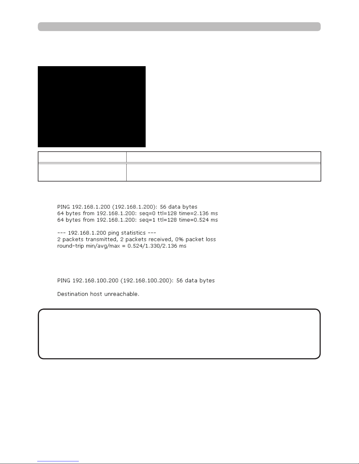
67
3.1.14 Connection Test
Checks if the network is connecting to DNS
server or SNTP server, etc.
Item Description
Destination IP Address
Click the [Execute] button to test the connection after
entering IP address to connect to.
•
Conrm information of the target IP address with network administrator.
• Connection test may result in an error even if the connection is performed
properly when the packets for checking the connection are discarded before
arriving at the target depending on the settings of rewall or packet ltering, etc.
• The result of the connection test is displayed only in English.
NOTE
3. Web Control
3.1 Projector Web Control (continued)
Display example of the connection succeeded :
Display example of the connection failed :
Page 68
68
3. Web Control
The Main window as shown above is
displayed at rst. However, if you have
enabled User Password on the Tools window
(&72), a dialog prompting you to enter
the password as shown on the right will be
displayed, and no operation is enabled until
you have entered the password. After entering
the preset password, the dialog disappears
and the Main window will be displayed.
As shown below, you can open a window by
clicking the corresponding tab at the top right
of the window.
3.2 Crestron e-Control
®
User Password dialog
Tab
Tab Description
Logout
Logs out from e-Control
®
.
This tab appears only when User Password of the Tools window is
enabled.
Tools Opens Tools window. (
&72)
Info Opens Info window. (
&74)
Contact IT Help Opens Help Desk window. (
&75)
Page 69

69
• In any of the following cases, the selection window does not appear
but the Login window of the Projector Web Control is displayed.
- Network Settings - Other Setup - Crestron e-Control is "Disable" (&45)
- Network Settings - Common Setup - Crestron is "OFF" (&42)
- NETWORK menu - EXTERNAL CONTROL - CRESTRON is "OFF" (&34)
Set Crestron to on and enable Crestron e-Control, then close the web browser.
Next, restart the web browser, followed by entering the projector's IP address.
• Only English is supported on Crestron e-Control®.
• If the connection is terminated, the "Loading..." screen will appear. Check the
connection between the projector and the computer, then return or refresh the
Web page.
• The control from Crestron e-Control® is supported only via wired LAN.
NOTE
3.2 Crestron e-Control
®
(continued)
3. Web Control
Page 70
70
3. Web Control
3.2 Crestron e-Control® (continued)
3.2.1 Main window
You can operate the basic controls of the projector on this screen.
• If the projector is in the standby mode, only the [Power] button can
be operated.
NOTE
1. Click a button and operate as follows.
Button Description
Power Turns the power on/off.
Vol - / Vol + Adjusts the volume setting.
Mute Turns Mute on/off.
2. Sources List
You can click a button to switch the input channel. The cursor will move
according to the currently selected input port.
Button Description
Computer In Selects input from COMPUTER IN port.
HDMI 1 Selects input from HDMI 1 port.
HDMI 2 Selects input from HDMI 2 port.
DisplayPort Selects input from DisplayPort port.
HDBaseT Selects input from HDBaseT
TM
port.
SDI (8980WU only) Selects input from SDI port.
Video Selects input from VIDEO port.
LAN Selects input from LAN port.
1
4
2
3
Page 71

71
3. Web Control
3.2 Crestron e-Control® - Main window (continued)
3. Click a button and operate as follows. To show the hidden buttons, click the ◄ /
► icons at the left and right ends.
Button Description
Freeze Turns Freeze on/off.
Contrast Adjusts the contrast setting.
Brightness Adjusts the brightness setting.
Color Adjusts the color setting.
Sharpness Adjusts the sharpness setting.
Magnify
Controls the magnication setting using the [+] / [-] buttons.
Use the [▲] [▼] [◄] [►] buttons to move to the area you want
to magnify.
Auto Performs the automatic adjustment.
Blank Turns the BLANK screen on/off.
4. Click the button and operate in the same way as the bundled remote control.
Button Description
Menu Assigned the same operation as MENU button.
Enter Assigned the same operation as ENTER button.
Reset Assigned the same operation as RESET button.
▲ Assigned the same operation as ▲ button.
▼ Assigned the same operation as ▼ button.
◄ Assigned the same operation as ◄ button.
► Assigned the same operation as ► button.
Page 72
72
3. Web Control
3.2 Crestron e-Control® (continued)
3.2.2 Tools window
Congures the settings between the projector and Crestron
®
control system.
Click the [Exit] button to return to the Main window.
1. Crestron Control
Congures the settings of Crestron
®
control system devices.
Item Description
IP Address Congures the IP address of the control system.
IP ID Congures the IP ID of the control system.
Port
Species the port number used for communication by the
control system.
To apply the settings, click the [Send] button.
2. Projector
Congures the network settings of the projector.
Item Description
Projector Name
Congures the name of the projector. The length of the
Projector Name can be up to 64 alphanumeric characters.
Location
Congures the location name of the projector. You can specify
a Location name up to 32 alphanumeric characters.
Assigned To:
Congures the user name for the projector. You can specify a
user name up to 32 alphanumeric characters.
The usable symbols are space and the following:
!"#$%&'()*+,-./:;<=>?@[\]^_`{|}~
To apply the settings, click the [Send] button.
1
4
5
3
2
• If two-byte characters are used, the input text or numbers cannot be
set correctly.
• Any items on this window cannot be left blank.
NOTE
Page 73
73
3. Web Control
3.2 Crestron e-Control® - Tools window (continued)
3. Projector (continued)
Congures the network settings of the projector.
Item Description
DHCP Enables DHCP.
IP Address Congures the IP address when DHCP is disabled.
Subnet Mask Congures the subnet mask when DHCP is disabled.
Default Gateway Congures the default gateway when DHCP is disabled.
DNS Server Congures the DNS server address when DHCP is disabled.
To apply the settings, click the [Send] button.
4. User Password
Congures the User Password. To prompt the entry of User Password before
starting e-Control
®
, select the checkbox.
Item Description
New Password
Congures the password.
You can specify a password up to 26 alphanumeric characters.
The usable symbols are space and the following:
!"#$%&'()*+,-./:;<=>?@[\]^_`{|}~
Conrm
Reenter the above password for verication. If the password is
incorrect, an error message is displayed.
To apply the settings, click the [Send] button.
5. Admin Password
Congures the Admin Password. To prompt the entry of Admin Password before
displaying the Tools window, select the checkbox.
Item Description
New Password
Congures the password.
You can specify a password up to 26 alphanumeric characters.
The usable symbols are space and the following:
!"#$%&'()*+,-./:;<=>?@[\]^_`{|}~
Conrm
Reenter the above password for verication. If the password is
incorrect, an error message is displayed.
To apply the settings, click the [Send] button.
Page 74
74
3. Web Control
3.2 Crestron e-Control® (continued)
3.2.3 Info window
Displays the current settings and status of the projector.
Click the [Exit] button to return to the Main window.
1. Projector Information
Item Description
Projector Name Displays the projector name settings.
Location Displays the location name of the projector.
MAC Address Displays the wired LAN MAC address of the projector.
Resolution
Displays the resolution and vertical frequency of the signal input
selected on the projector.
Lamp Hours Displays the usage time for the lamp.
Assigned To: Displays the user name for the projector.
2. Projector Status
Item Description
Power Status Displays the power status.
Input Source Displays the input signal source.
Picture Mode Displays the picture mode setting.
Installation Displays the installation setting.
Eco Mode Displays the eco mode setting.
Error Status Displays the error status.
1 2
• Projector Name, Location and the user name for Assigned To: may
appear truncated if they are too long.
NOTE
Page 75
75
3. Web Control
3.2 Crestron e-Control® (continued)
3.2.4 Help Desk window
Sends/receives messages to/from the administrator for Crestron RoomView
®
Express and Fusion RV®.
Button Description
Send Sends a message.
Checks the received message.
Page 76
76
3. Web Control
3.2 Crestron e-Control® (continued)
3.2.5 Emergency Alert
When the administrator for Crestron RoomView
®
Express and Fusion RV® sends
out an alert message, it will be displayed on the screen.
You can reply to the alert message via a chat format. Input a message in the box
below the alert message, and click the [Send] button.
• For details of Emergency Alert, refer to the manual of Crestron
RoomView® Express or Fusion RV®.
• The alert message from Crestron RoomView® and Fusion RV® is displayed
on the screen of the projector in the way similar to the real-time text of the
Messenger function. (&82) If another real-time text is displayed on the screen,
it will be overwritten by the alert message. However, if the priority of the real-
time text is set to high, the alert message does not appear on the screen. For
details, refer to the manual for the application of the Messenger.
NOTE
Page 77
77
4. Network Presentation
4. Network Presentation
The projector can display or play back the computer screen images and audio
data that are transmitted through the network. This Network Presentation feature
helps you to smoothly make your presentations and conduct conferences.
4.1 Outline
For details of Network Presentation and instructions to install the "LiveViewer",
refer to the manual for "LiveViewer".
• The use of "LiveViewer" function depends on the model you are
using. If you want to use the latest "LiveViewer", please refer to the appropriate
group item in the "LiveViewer" User's Manual. This model will be in the Group
of H.
•
For Mac user, download the software from the website. Refer to 2.5. Applications.
NOTE
Page 78

78
4. Network Presentation
LiveViewer has two display modes, Single PC mode and Multi PC mode.
4.2 Display Mode
The Single PC mode can display images in full screen from one computer to the
projector/switcher via wireless LAN or wired LAN.
4.2.1 Single PC mode
■ Presenter Mode
In the Single PC mode, the projector can be occupied by one computer and
can block access from any other computers (if Presenter Mode is set to ON in
LiveViewer). While making your presentation, you don’t need to worry that the
image on screen will be unexpectedly switched to an image sent by another
computer. Presenter Mode can be set to ON in the option menu in the LiveViewer.
The projector can display images of up to four computers connected at the same
time.
4.2.2 Multi PC mode
Page 79
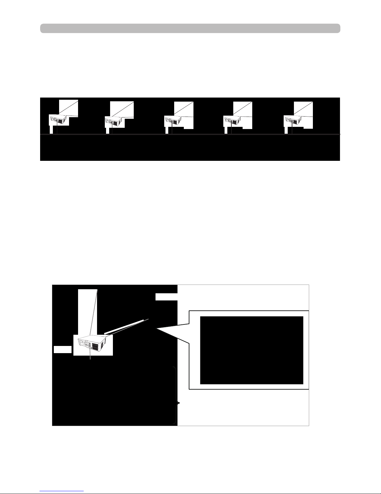
79
4. Network Presentation
In the Multi Projector/Multi Display mode, up to 12 projectors or switchers
connected to projectors can connect with the computer via wireless or wired LAN
simultaneously.
4.3 Multi Projector Mode
4.4 Moderator Control Mode
This function is for Windows users only.
This function is for Windows users only.
One computer can be assigned as Moderator (Host) to control all other computers
(Clients) or the switchers connected with the projector via wireless LAN or wired
LAN. Since Clients cannot control the LiveViewer and the projector, the Host can
proceed with the program as arranged smoothly and safely.
LAN
Moderator (Host)
Clients
Page 80
80
4. Network Presentation
The port numbers used for LiveViewer are shown below.
4.5 Port Number
Port No. Protocol
5500 TCP
5900 TCP
9720 TCP
• When other application uses the ports above, LiveViewer and Projector Quick
Connection may not work.
NOTE
Page 81
81
5. MyImage Function
The projector can display still images transferred via the network.
It is possible to allocate up to 4 image les.
MY IMAGE transmission requires an exclusive application for your computer.
Use the application to transfer the image data.
For information on the necessary settings and operations for the computer and
projector, refer to the manual for the application.
To display the transferred image, select the MY IMAGE item in the NETWORK
menu. For more information, please see the description of the MY IMAGE item of
the NETWORK menu.
5. My Image Function
• Using MY BUTTON registered as MY IMAGE can display transferred
image. (&OPTION menu in the Operating Guide)
• The image le also can be displayed by using schedule function from the web
browser.(&94)
•
If data is transferred via wireless and wired LAN at the same time, the projector
may not be able to process the data correctly
.
NOTE
Page 82
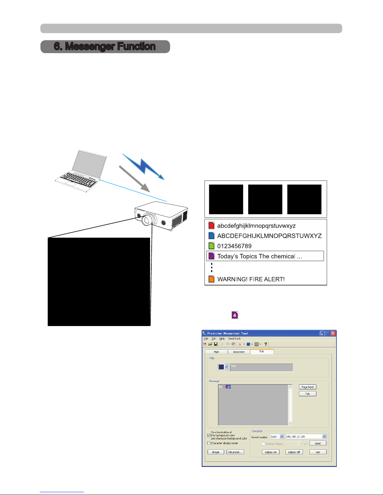
82
6. Messenger Function
The projector can display text data transferred via the network on the screen and
play back audio data inside the projector.
The text data can be displayed on the screen in two ways. One is to display the
text transferred from the computer on real time, and the other is to choose the text
data stored in the projector and display it.
It is possible to store up to 12 text data.
6. Messenger Function
6.1 Outline
Transfer text data
Display text data (ex.
)
1
4
3
2
12
1
4
3
2
12
Page 83

83
Messenger function requires an exclusive application for your computer. To edit,
transfer and display the text data, use the application.
For information on the necessary settings and operations for the computer and
projector, refer to the manual for the application.
6. Messenger Function
The languages that can be displayed by Messenger function are shown below.
English, French, German, Spanish, Italian, Norwegian, Dutch, Portuguese,
Swedish, Finnish, Danish, Brasileiro, Indonesian, Lithuanian, Estonian, Latvian,
Polish, Czech, Hungarian, Slovenian, Croatian, Russian, Turkish, Greek,
Japanese, Simplied Chinese, Traditional Chinese, Korean, Vietnamese
6.2 Supported Languages
There are 4 types of message display style. The following is the description of
each type.
6.3 Display Style
1) Scroll
The message scrolls to the left in the message
display area.
2) Box (Scroll up)
The message scrolls upwards in the square
message display area.
The chemical class
Today’s
Page 84
84
6. Messenger Function
3) Pop on
The message is displayed in full view in the
square message display area.
4) Picture Side
The message is displayed in the message
display area on the right or left.
This style is available only for WXGA and
WUXGA model projector.
• Using MY BUTTON registered as MESSENGER can turn the
displaying messenger text on/off. (&OPTION menu in the Operating Guide)
• The text le also can be displayed by using schedule function via the web
browser. (&94)
•
If data is transferred via wireless and wired LAN at the same time, the projector
may not process the data correctly.
NOTE
Page 85
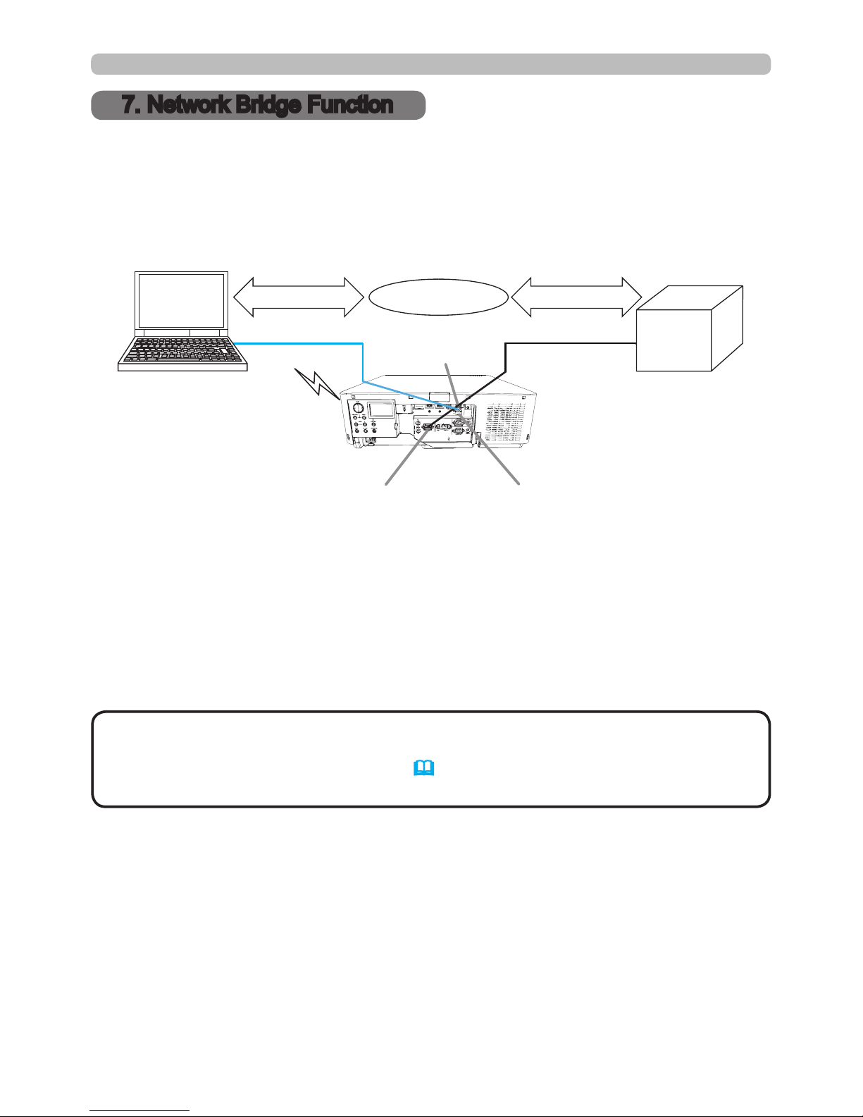
85
7. Network Bridge Function
This projector is equipped with the NETWORK BRIDGE function to perform
mutual conversion of a network protocol and a serial interface.
By making use of the NETWORK BRIDGE function, a computer connected to the
projector via wireless or wired LAN is able to control an external device via RS-
232C communication using the projector as a network terminal.
7.1 Connecting devices
1) Connect the projector’s LAN port to the computer’s LAN port with a LAN cable,
or insert the USB wireless adapter into the WIRELESS port.
2) Connect the projector’s CONTROL port and the device’s RS-232C port with an
RS-232C cable, for RS-232C communication.
• Before connecting the devices, read the manuals for the devices to
ensure the connection.
For RS-232C connection, check the specications of
each port and use the suitable cable. (&Connection to the ports in the Operating
Guide - Technical)
NOTE
7. Network Bridge Function
RS-232C
RS-232C cable
CONTROL port
LAN port
External device
Wired LAN
LAN cable
Computer
TCP/IP data
Serial data
WIRELESS port
(USB wireless
adapter)
Wireless
LAN
Protocol change
Page 86
86
7. Network Bridge Function
7.2 Communication setup
7.3 Communication port
1) In the COMMUNICATION TYPE menu, select NETWORK BRIDGE
(WIRELESS or WIRED depending on the type of connection you use) for the
CONTROL port.
2) Using the SERIAL SETTINGS menu, select the proper baud rate and parity
for the CONTROL port, according to the specication of the RS-232C port of
the connected device.
For the NETWORK BRIDGE function, send the data from the computer to the
projector with using the Network Bridge Port congured in the Port Settings of
web browser. (
&46)
3) Using the TRANSMISSION METHOD menu, set up the proper method for the
CONTROL port according to your use.
• The OFF is selected for the COMMUNICATION TYPE as the default
setting.
• Using the COMMUNICATION menu, set up the communication. Remember
that an unsuitable setup could cause malfunction of communication.
• When either one of the NETWORK BRIDGE settings is selected in the
COMMUNICATION TYPE menu, RS-232C commands cannot be received from
the CONTROL port.
• Except for 41794, 9715, 9716, 9719, 9720, 5900, 5500, 4352
between 1024 and 65535 can be set up as the Network Bridge Port number.
It is set to 9717 as the default setting.
NOTE
NOTE
Item Condition
BAUD RATE 4800bps/9600bps/19200bps/38400bps
PARITY NONE/ODD/EVEN
Data length 8 bit (xed)
Start bit 1 bit (xed)
Stop bit 1 bit (xed)
To congure the setup of the communication using NETWORK BRIDGE for
the projector, use items in the COMMUNICATION menu. Open the menu of
the projector and select the OPTION - SERVICE - COMMUNICATION menu.
(&OPTION menu > SERVICE > COMMUNICATION in the Operating Guide)
Page 87
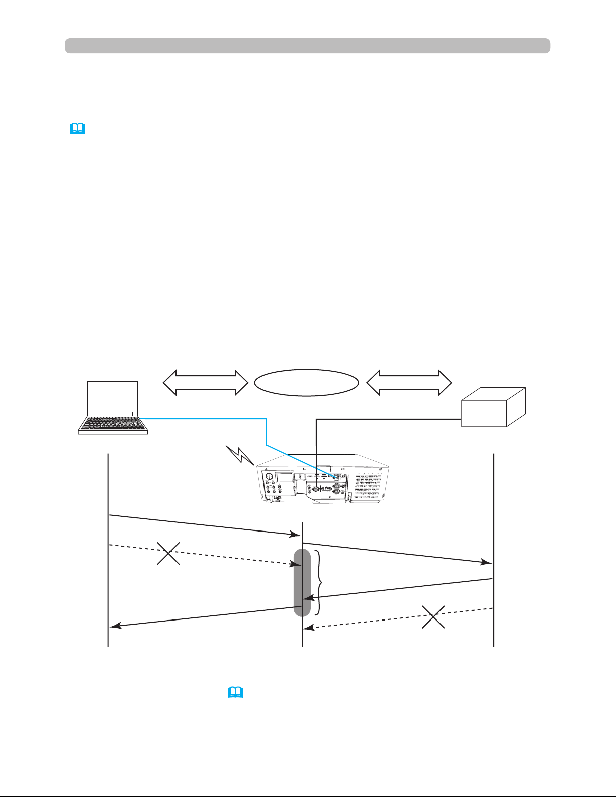
87
7.4 Transmission method
7.4.1 HALF-DUPLEX
The transmission method can be selected from the menus, only when the
NETWORK BRIDGE is selected for the COMMUNICATION TYPE.
(
&OPTION menu > SERVICE > COMMUNICATION in the Operating Guide)
HALF-DUPLEX FULL-DUPLEX
This method lets the projector make two way communication, but only one
direction, either transmitting or receiving data, is allowed at a time.
The method does not allow the projector to receive the data from the computer
while waiting for response data from an external device. After the projector
receives the response data from an external device or the response limit time is
past, the projector can receive the data from the computer.
That means that the projector controls transmitting and receiving the data to
synchronize the communication.
To use the HALF-DUPLEX method, set up the RESPONSE LIMIT TIME following
the instructions below.
Using the RESPONSE LIMIT TIME menu, set the waiting time for response data
from an external device. (
&OPTION menu > SERVICE > COMMUNICATION in
the Operating Guide)
OFF 1s 2s 3s ( OFF)
7. Network Bridge Function
RS-232C
RS-232C cable
External device
Wired LAN
LAN cable
Computer
Protocol change
TCP/IP data Serial data
Transmitting data
Discarding data
Transmitting data
Response limit
time
Response data
Response data
Wireless LAN
Discarding data
Page 88
88
• With using the HALF-DUPLEX method, the projector can send out
254 byte data at the maximum at a time.
• If it is not required to monitor the response data from an external device and
the RESPONSE LIMIT TIME is set to OFF, the projector can receive the data
from the computer and send it out to an external device continuously.
The OFF is selected as the default setting.
•
When the computer controls the synchronization of receptions and transmissions,
the external device may not be controlled properly depending on the status of data
processing of the projector.
NOTE
NOTE
7.4.2 FULL-DUPLEX
This method lets the projector make two way communication, transmitting and
receiving data at the same time, without monitoring response data from an
external device.
With using this method, the computer and an external device will send the data
out of synchronization. If it is required to synchronize them, set the computer to
make the synchronization.
7. Network Bridge Function
7.4 Transmission method (continued)
Page 89
89
8. Other Functions
8.1 E-mail Alerts
The projector can automatically send an alert message to the specied e-mail
addresses when the projector detects a certain condition that is requiring
maintenance or detected an error.
• Up to ve e-mail addresses can be specied.
• The projector may be not able to send e-mail if the projector suddenly loses
power.
•
Mails may not be sent correctly depending on the mail environment you are
using.
NOTE
8. Other Functions
Alerts available to E-mail alerts are as follows.
Item Description
Cover Error The lamp cover has not been properly xed.
Fan Error The cooling fan is not operating.
Lamp Error
The lamp does not light, and there is a possibility that
interior portion has become heated.
Temp Error
There is a possibility that the interior portion has become
heated.
Air Flow Error The internal temperature is rising.
Cold Error
There is a possibility that the interior portion has
become overcooled.
Filter Error Filter time over.
Shade Error The shutter does not work correctly.
Lens Shift Error The Lens shift does not work correctly.
AC Blackout Error Power supply was interrupted momentarily.
Other Error
Errors other than the above.
If this error is displayed, please contact your dealer.
Schedule Execution
Error
Failed to execute scheduled events.
Lamp Time Alarm Lamp Time has exceeded the specied alarm limit.
Filter Time Alarm Filter Time has exceeded the specied alarm limit.
Filter Status Notication
The status to clean the air lter is changed.
Transition Detector
Alarm
Transition Detector Alarm. (
&SECURITY menu in the
Operating Guide)
(continued on next page)
Page 90

90
8. Other Functions
• The timing of receiving Filter Error e-mail is depending on the FILTER
MESSAGE setting in the LAMP & FILTER item of the SETUP menu which
determines the period until the lter message is displayed on the projector
screen. An e-mail will be sent when the usage time of the lter exceeds the set
time limit. No notication e-mail will be sent if the FILTER MESSAGE is set to
OFF. (&SETUP menu in the Operating Guide)
• Lamp Time Alarm is a threshold for e-mail notication of the lamp time.
When the set time exceeds the limit congured in the Projector Web Control,
an e-mail will be sent.
•
Filter Time Alarm is a threshold for e-mail notication of the lter time. When
the set time exceeds the limit congured in the Projector Web Control, an e-mail
will be sent.
• Filter Status Notication can be enabled for both or either one of Status
1 and 2. These notications are equivalent to the changing of the FILTER
indicator on the projector. (Status 1: off to orange, Status 2: orange to red)
Refer to the Operating Guide for details of the FILTER indicator.
NOTE
Page 91

91
8. Other Functions
To use the projector’s e-mail alert function, please congure the following items
through a web browser.
Mail Settings (
&48)
1) Select [Mail Settings] on main menu in Projector Web Control.
2) Congure each item in Mail Settings page. Refer to item 3.1.5 Mail Settings
(
&48) for further information.
3) Click the [Apply] button to save the settings.
4) Click the [Send Test Mail] button to conrm that the e-mail settings are
correct.
The following mail will be delivered to the specied addresses.
Subject line : Test Mail <Projector name>
Text : Send Test Mail
Date <Testing date>
Time <Testing time>
IP Address <Projector IP address>
MAC Address <Projector MAC address>
Alert Settings (
&50)
1) Select [Alert Settings] on main menu in Projector Web Control.
2) Select and congure each alert item. Refer to item 3.1.6 Alert Settings (
&50)
for further information.
3) Click the [Apply] button to save the settings.
Failure/Warning e-mails are formatted as follows:
Subject line : <Mail title> <Projector name>
Text : <Mail text>
Date <Failure/Warning date>
Time <Failure/Warning time>
IP Address <Projector IP address>
MAC Address <Projector MAC address>
Page 92
92
8. Other Functions
8.2 Projector Management using SNMP
The SNMP (Simple Network Management Protocol) enables to manage the
projector information, which is a failure or warning status, from the computer on
the network.
• It is recommended that SNMP functions are executed by a network
administrator.
• SNMP management software must be installed on the computer to monitor
the projector via SNMP.
NOTE
Standard MIB (MIB-2)
You can refer the following items dened in system group of Standard MIB (MIB-2).
Item Description
sysName Projector name is set.
sysLocation The information on where it is located. It has character string
set in sysLocation (SNMP) in Projector Web Control - [Network
Settings] - [Common Setup].
sysContact The information on the administrator's contact information. It
has character string set in sysContact (SNMP) in Projector
Web Control - [Network Settings] - [Common Setup].
Enhanced MIB
You can get conguration information by using Enhanced MIB for projectors.
Enhanced MIB for projectors can be downloaded from [Port Settings] page in
Projector Web Control.
Trap
When an error or warning occurs in the projector, a notication can be sent to the
specied address.
In addition to e-mail alert shown in 8.1 Email Alerts (
&89), the following
notication can be sent.
Item Description
Cold Start When the projector is supplied with the power, it works as
below.
• If the STANDBY MODE is set to the NORMAL: the projector's
power status changes from “OFF” to “Standby state”.
• If the STANDBY MODE is set to the SAVING: the projector's
power status changes from “Standby state” to “ON (lamp is
turned on)”.
(
&
SETUP menu in the Operating Guide).
Authentication Failure The SNMP access is detected from the invalid SNMP
community.
Page 93
93
8. Other Functions
Setup the following functions through WEB browser, if you want to manage the
projector by SNMP.
Port Settings (
&46)
1) Select [Port Settings] on main menu in Projector Web Control.
2) Click the [Download MIB le] to download a MIB le.
3) Click the [Enable] check box to open the SNMP Port. Set the address to send
the SNMP trap to when a Failure/Warning occurs.
Security Settings (&58)
1) Select [Security Settings] on main menu in Projector Web Control.
2) Click the [SNMP] and set the community name on the screen that is displayed.
Alert Settings (&50)
Congure the settings for Trap transmission of Failures/Warnings.
1) Select [Alert Settings] on main menu in Projector Web Control.
2) Select the Failure/Warning item to be congured.
3) Click the [Enable] check box to send out the SNMP trap for Failures/Warnings.
Clear the [Enable] check box when SNMP trap transmission is not required.
4) Click the [Apply] button to save the settings.
•
Register the downloaded MIB le to SNMP manager program to be used.
• Be sure to execute Network Restart when the settings of [Port Settings] or
[Security Settings] is changed.
NOTE
Page 94

94
8.3 Event Scheduling
The scheduling function enables to setup scheduled events including power on /
power off. It enables to be “self-management” projector.
Note the following before setting the schedule.
• Schedule can also be set in OPTION - SCHEDULE menu of the
projector. (&Refer to Operating Guide – OPTION).
• A maximum of 16 programs of schedule can be set. A maximum of 20 events
can be registered in 1 program.
• No events are registered in program 1 – 16 with factory default settings. The
program is required to be set in advance when using the schedule function for
the rst time.
• The priority for scheduled events is as follows 1) specic date 2) weekly
• Up to 10 specic dates are available for scheduled events. Priority is given to
those with the lower numbers when more than one event has been scheduled
for the same date and time (e.g., ‘Specic date No. 1’ has priority over ‘Specic
date No. 2’ and so on.
• The power on event has the lowest priority among all the events that are set
at the same time.
• Be sure to set the date and time before enabling scheduled events. (&56)
• After the projector is moved, check the date and time set for the projector
before conguring the schedules.
•
The internal clock’s time may not remain accurate. Using SNTP is recommended
to maintain accurate time.
• Certain error state in the projector (such as temperature error, lamp error) will
prevent the projector from appropriate execution of scheduled functions/events.
• Events “My Image” and “Messenger” will not be executed appropriately and
result in “schedule execution error” status when the lamp does not light and/or
data to be displayed are not stored in the projector at the time when scheduled
event is executed.
• Events “Input Source” and “My Image” is not executed if security function is
enabled and the projector is locked due to the function.
NOTE
8. Other Functions
Page 95
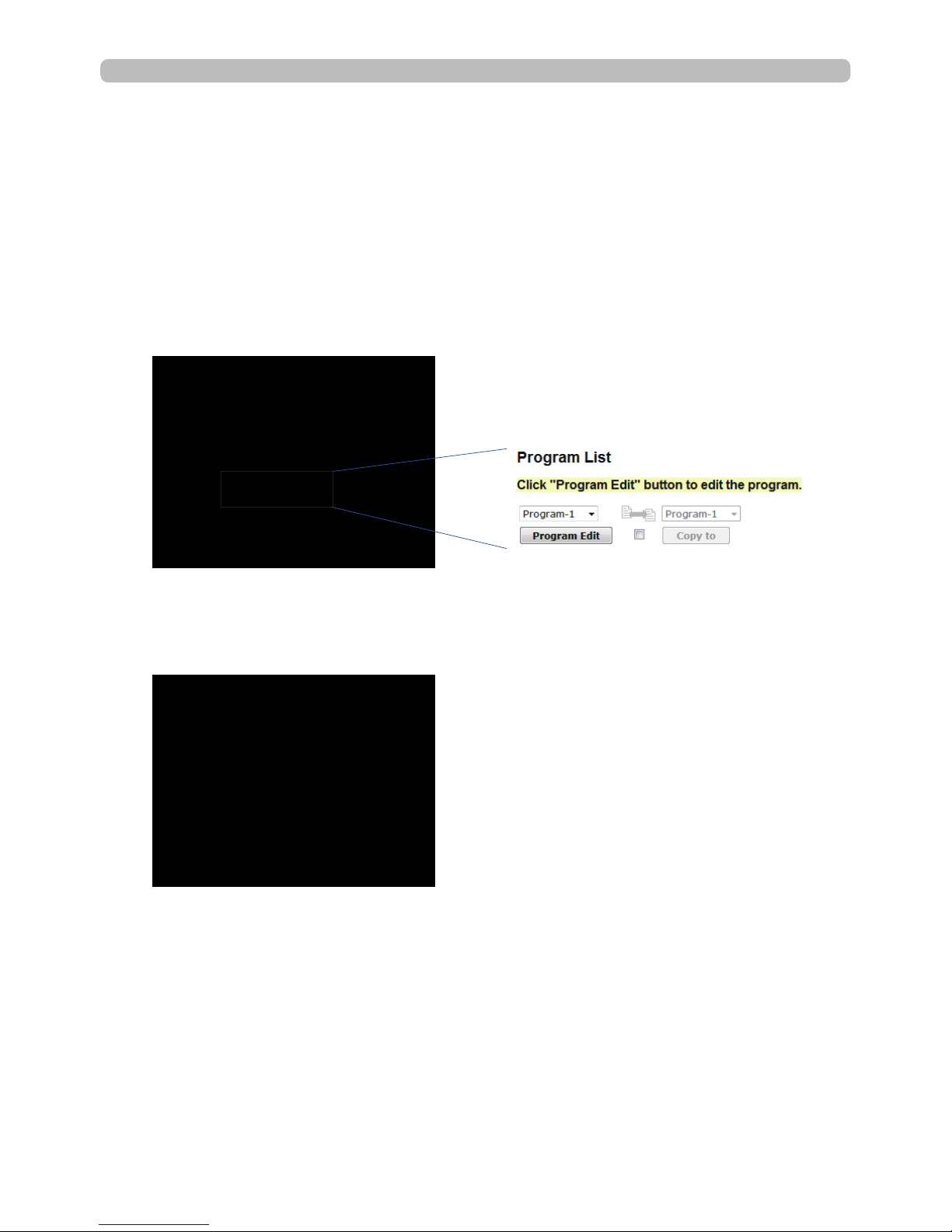
95
8. Other Functions
The procedure to set the schedule in Projector Web Control is described in the
following.
Setting the program is necessary to use the schedule function. Various events
such as power on/off or switching input source, and the time to execute the events
are to be registered in the program. No events are registered in program 1 – 16
with factory default settings. Set the program following the steps below.
In the case that the program has already been set, skip to step 6).
1) Select [Schedule Settings] on main menu in Projector Web Control.
2) Select the program number in dropdown list under Program List and click the
[Program Edit] button to display the following program edit display. The display
for editing Program-1 is shown below.
3) After setting the time, events and parameters, click the [Register] to add the
new event.
Click the [Delete] button when you want to delete an event.
Click the [Delete All] button when you want to delete all the events in the currently
selected program.
Page 96
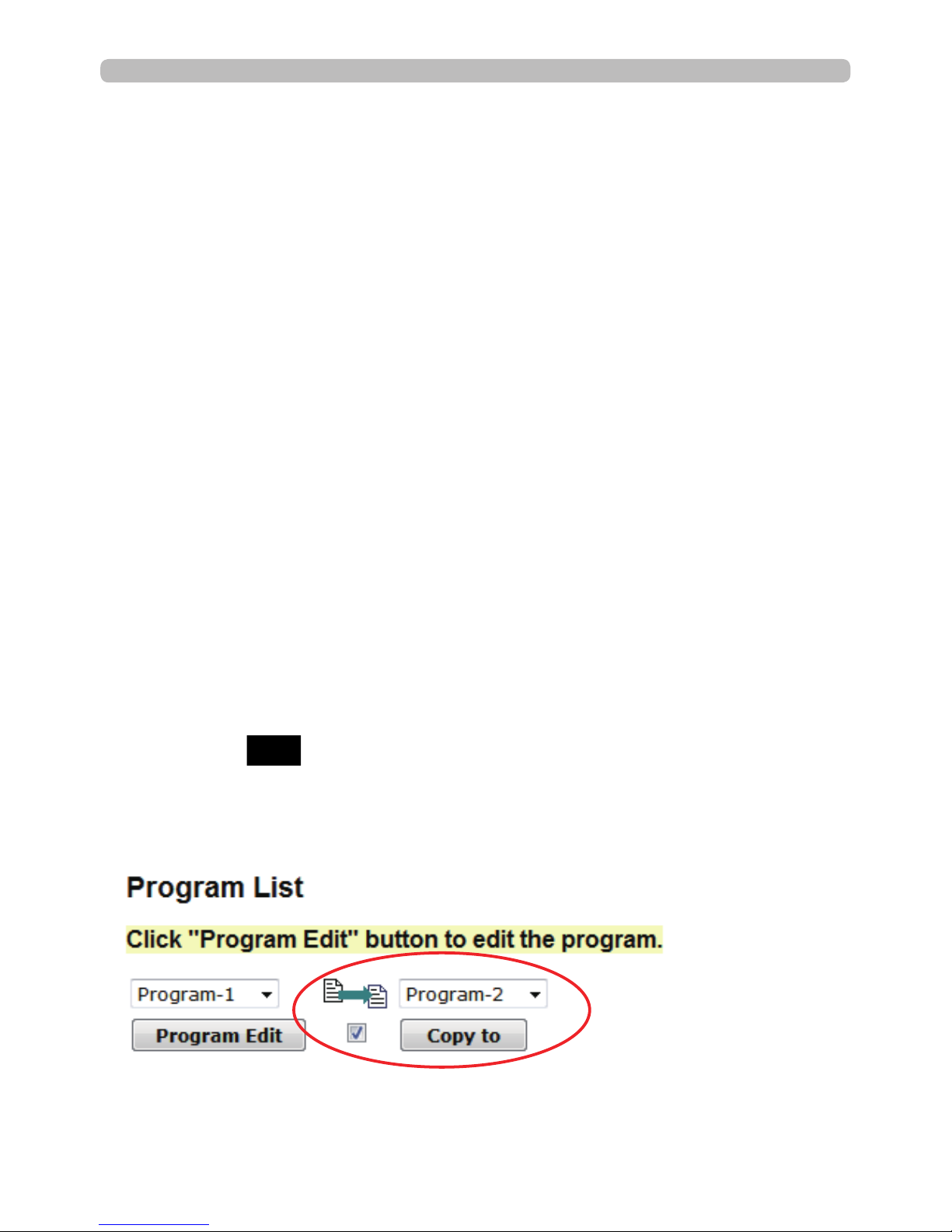
96
4) When you want to edit the program with other number continuously, select the
program you want to edit in dropdown list and click the [Select] button to display
the display for editing the selected program.
5) Click the [Back] button to go back to schedule management screen after
nishing the program setting.
The procedure to assign the program set in the step 1) ~ 5) to the schedule is
described in the following.
6) Click the checkbox of the schedule to be executed (e.g. Click the checkbox of
“Monday”, when it is to be executed on Mondays) in the schedule management
screen.
7) Select the program to be executed in dropdown list. You can conrm the event
information registered in each program in the program list on the bottom of the
screen.
When setting the Specic date No.1 ~ 10, enter the date (month/day).
8) Click the [Apply] button to save the schedule settings in the projector.
Repeat step 6) ~ 8) similarly to set the schedule you want to execute.
The schedule settings are now complete.
Finally, conrm the time stored in the projector is correctly set.
■How to copy the program
When you copy the currently selected program to other program, click the
checkbox under icon. Click the [Copy to] button after selecting the program
to which you want to copy in dropdown list.
The same program as the currently selected one cannot be specied as the
program to which you want to copy.
8. Other Functions
Page 97

97
8.4 Command Control via the Network
You can congure and control the projector via the network using RS-232C
commands.
Communication Port
The following two ports are assigned for the command control.
Command Control Settings (
&46)
4) Click the [Enable] check box to open Network Control Port1 (Port: 23) to use
TCP #23. Click the [Enable] check box for the [Authentication] setting when
authentication is required, otherwise clear the check box.
5) Click the [Enable] check box to open Network Control Port2 (Port: 9715) to
use TCP #9715. Click the [Enable] check box for the [Authentication] setting
when authentication is required, otherwise clear the check box.
6) Click the [Apply] button to save the settings.
Congure the following items from a web browser when command control is used.
Example: If the IP address of the projector is set to 192.168.1.10:
1) Enter “http://192.168.1.10/” into the address bar of the web browser, and select
Projector Web Control from the selection window.
2) Enter your user name and password, and then click the [OK].
3) Click the [Port Settings] on the main menu.
8. Other Functions
TCP #23 (Network Control Port1 (Port: 23))
TCP #9715 (Network Control Port2 (Port: 9715))
• Command control is available only via the specied port above.
NOTE
Page 98

98
8.4 Command Control via the Network (continued)
When the authentication setting is enabled, the following settings are required.
(
&58)
7) Click the [Security Settings] on the main menu.
8) Click the [Network Control] and enter the desired authentication password.
* See NOTE.
9) Click the [Apply] button to save the settings.
NOTE
8. Other Functions
• The Authentication Password will be the same for Network Control
Port1 (Port: 23), Network Control Port2 (Port: 9715), PJLink™ Port (Port:
4352), My Image Port (Port: 9716) and Messenger Port (Port: 9719).
• The new conguration settings are activated after restarting the network
connection. When the conguration settings are changed, you must restart
the network connection. You can restart the network connection from Network
Restart on the main menu. (&66)
Page 99

99
Command Format
Command formats differ among the different communication ports.
● TCP #23
You can use the RS-232C commands without any changes. The reply data
format is the same as the RS-232C commands. (
&
RS-232C Communication in
the Operating Guide - Technical)
However, the following reply will be sent back in the event of authentication
failure when authentication is enabled.
Header Data length RS-232Ccommand Check Sum
Connection
ID
0x02 0x0D 13 bytes 1 byte 1 byte
Reply Error code
0x1F 0x04 0x00
<Reply in the event of an authentication error>
Header → 0x02, Fixed
Data length → RS-232C commands byte length (0x0D, Fixed)
RS-232C command → RS-232C commands that start with 0xBE 0xEF
(13 bytes)
Check Sum → This is the value to make zero on the addition of the
lower 8 bits from the header to the checksum.
Connection ID → Random value from 0 to 255 (This value is attached
to the reply data)
● TCP #9715
Send Data format
The following formatting is added to the header (0 x 02), Data length (0 x 0D),
Checksum (1 byte) and Connection ID (1 byte) of the RS-232C commands.
8. Other Functions
8.4 Command Control via the Network (continued)
Page 100
100
Reply
Connection
ID
0x06 1 byte
Reply
Connection
ID
0x15 1 byte
Reply Error code
Connection
ID
0x1C 2 bytes 1 byte
Reply Data
Connection
ID
0x1D 2 bytes 1 byte
Reply Status code
Connection
ID
0x1F 2 bytes 1 byte
Reply
Authentication
Error code
Connection
ID
0x1F 0x04 0x00 1 byte
8. Other Functions
8.4 Command Control via the Network (continued)
Reply Data format
The connection ID (the data is same as the connection ID data on the sending
data format) is attached to the RS-232C commands reply data.
<ACK reply>
<NAK reply>
<Error reply>
<Data reply>
<Projector busy reply>
<Authentication error reply>
 Loading...