

Page 1

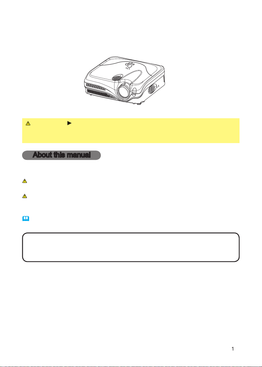
LCD Projector
Model 8914
USER’S MANUAL
401-8914-00
Page 2

Page 3
8914
Thank you for purchasing this projector.
WARNING
After reading them, store them in a safe place for future reference.
About this manual
Various symbols are used in this manual. The meanings of these symbols are
WARNING
This symbol indicates information that, if ignored, could possibly
This symbol indicates information that, if ignored, could possibly
Please refer to the pages written following this symbol.
• The information in this manual is subject to change without notice.
without express written consent.
Trademark acknowledgment
All other trademarks are the properties of their respective owners.
Before using this product, please read this Manual and
related manuals to ensure the proper use of this product.
Page 4
About this manual
. . . . . . . . . .
. . . . . . . . . . . . . . . . . .
2
. . . . . . . . . .
About contents of package
. . . . . . . . . . . . . . .
4
. . . . . . . . . . . . . . . . . . . . .
4
. . . . . . . . . . . . . . . .
Arrangement
Adjusting the projector's elevator
. .
About the fi lter cover for bottom-up use
. .
. . . . . . . .
. . . . . . . .
. . . . . . . . . . . . .
Turning on the power
. . . . . . . . . . .
Turning off the power
Adjusting the volume
. . . . . . . . . . .
Temporarily muting the sound
. . . .
. . . . . . . .
. . . . . . . .
Adjusting the zoom and focus
Adjusting the position
. . . . . . . . . .
. . . . . . . .
22
Content
Content
. . . . . . . . . . . . . . . . . .
23
Aspect, Mode, Brightness, Contrast,
. . . . . . . . . . . . . . .
25
28
Aspect, Over scan, V. position, H. position,
Whisper, Mirror, Volume, Audio
. . . . . . . . . . . . . . .
. . . . . . . . . . . . . . . .
Auto
search, Auto off, Lamp time,
. . . . . . . . . . . . .
Air fi lter
40
Troubleshooting
. . . . . . . . . .
42
. . . . . . . . . . . . .
42
. . . .
44
Correcting the keystone distortions 20
Using the magnify feature . . . . . . . 20
Freezing the screen . . . . . . . . . . . . 21
Temporarily blanking the screen . . 21
Multifunctional settings . . . . 22
mistaken for machine defects . . . . 46
Warranty and after-service
. . . 48
Specifi cations . . . . . . . . . . . . 48
Technical Guide . . . . . . . . . 1-14
Page 5
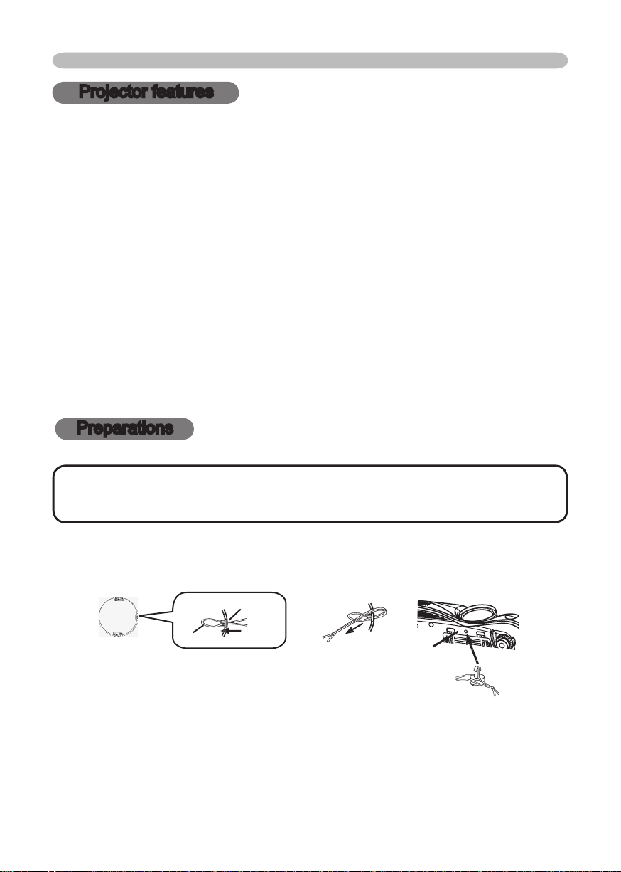
To avoid losing the lens cover, please fasten it the lens cap to the projector using
the strap.
Projector features / Preparations
Projector features
Low Noise
Compact Body
Preparations
• Keep the original packing materials for future reshipment. For
This projector is used to project various computer signals as well as NTSC/PAL/
SECAM video signals onto a screen. It requires a small space for installation
and produces a large image from a short distance.
High Brightness
Newly developed 230W UHB (Ultra High Brightness) lamp gives you a
bright image on a screen. The image is bright enough for use in lighted
rooms.
WHISPER mode is available for quieter operation. It is perfect for
use in low luminance rooms where low noise is more
Even with its many features, this projector is extremely compact and slim.
Page 6
Y
VIDEO
RGB IN1 RGB IN2
RGB OUT CONTROL
AUDIO 1-IN
S-VIDEO
COMPONENT VIDEO
CB/P
B
CR/P
R
R-AUDIO 2-L
AUDIO-OUT
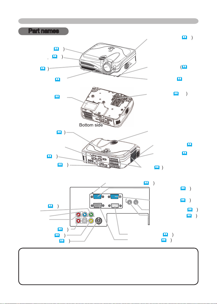
Part names
Zoom knob (
Zoom knob (
Vent (
AC inlet (
VIDEO ports (
/P
/P
VIDEO port (
Part names
Vent (
AUDIO-OUT port (
AUDIO 1-IN port (
AUDIO 2 L/R port (
This projector is controlled by an internal
turning on again, make the projector cool down at least 10 minutes without
46
Page 7

VIDEO button (
ASPECT button (
ON button (
OFF button (
Part names
44,45
TEMP indicator (
44,45
AUTO button (
VOLUME button (
VIDEO
RG
B
SEARC
H
FREEZE
OFF
ON
MAGNIFY
ASPECT AUTO
BLAN
K
MUTE
VOLUME
KEYSTONE
POSITION
ES
C
ENTE
R
MENU
RESE
T
Page 8

Setting up
Setting up
WARNING
wobbly or inclined stand.
the air fi lter.
The high temperature of the projector could cause a fi re, a burn and/or
walls.
place the projector near a humidifi er, a smoking space or a kitchen.
Page 9
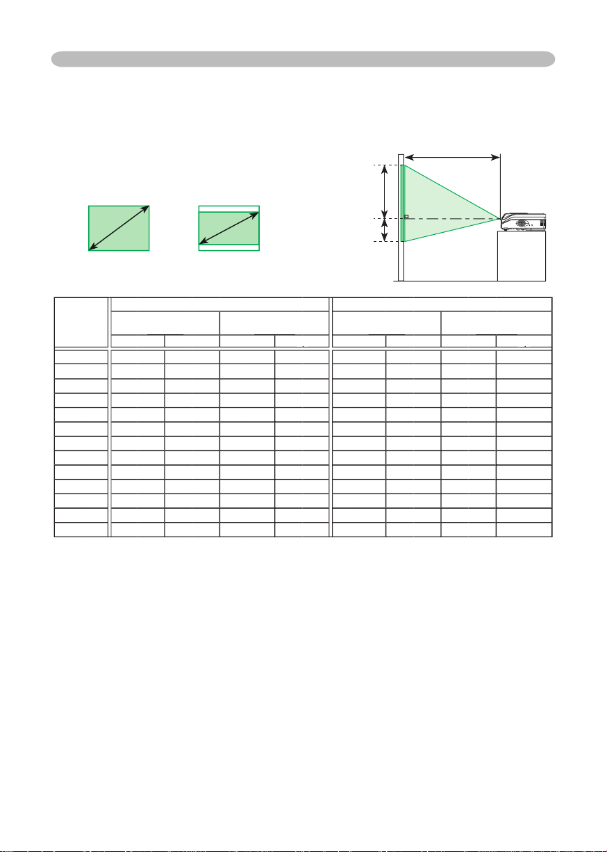
Arrangement
The values shown in the table are calculated for a full size screen: 1024 x 768
Setting up
4:3
For the model 8914/8915
size
4 : 3 screen
down
down
40648
8
69
2.0
60
60
2.2
2.0
2.4
-2
2.1
2.6
2.3
2.8-384
80
2.9
2.6
-3
4.0
-4
4.0
4.8
-5
4.623206
6.0
-6
200
6.1
274
6.7
-8
241
250
8.4
-10
46
Page 10
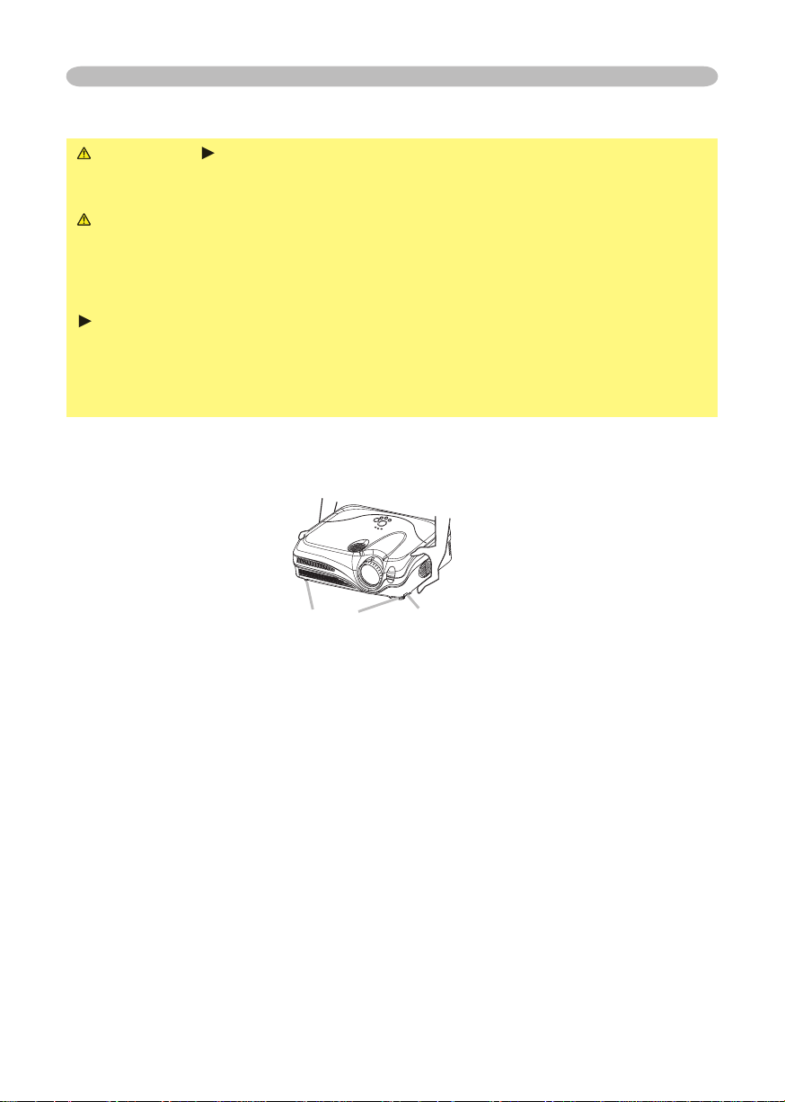
Adjusting the projector's elevator
WARNING
the projector might crash down, overturn, smash your fi ngers and possibly
To prevent damaging the projector and injuring yourself,
You can use the elevator feet to make adjustments if the surface on which you
After making sure that the projector is cool adequately, press and hold in the
The elevator buttons and the elevator feet are on the both sides.
When you release the elevator buttons, the elevator feet will lock into position.
the elevator feet by hand.
Setting up
Page 11
Setting up
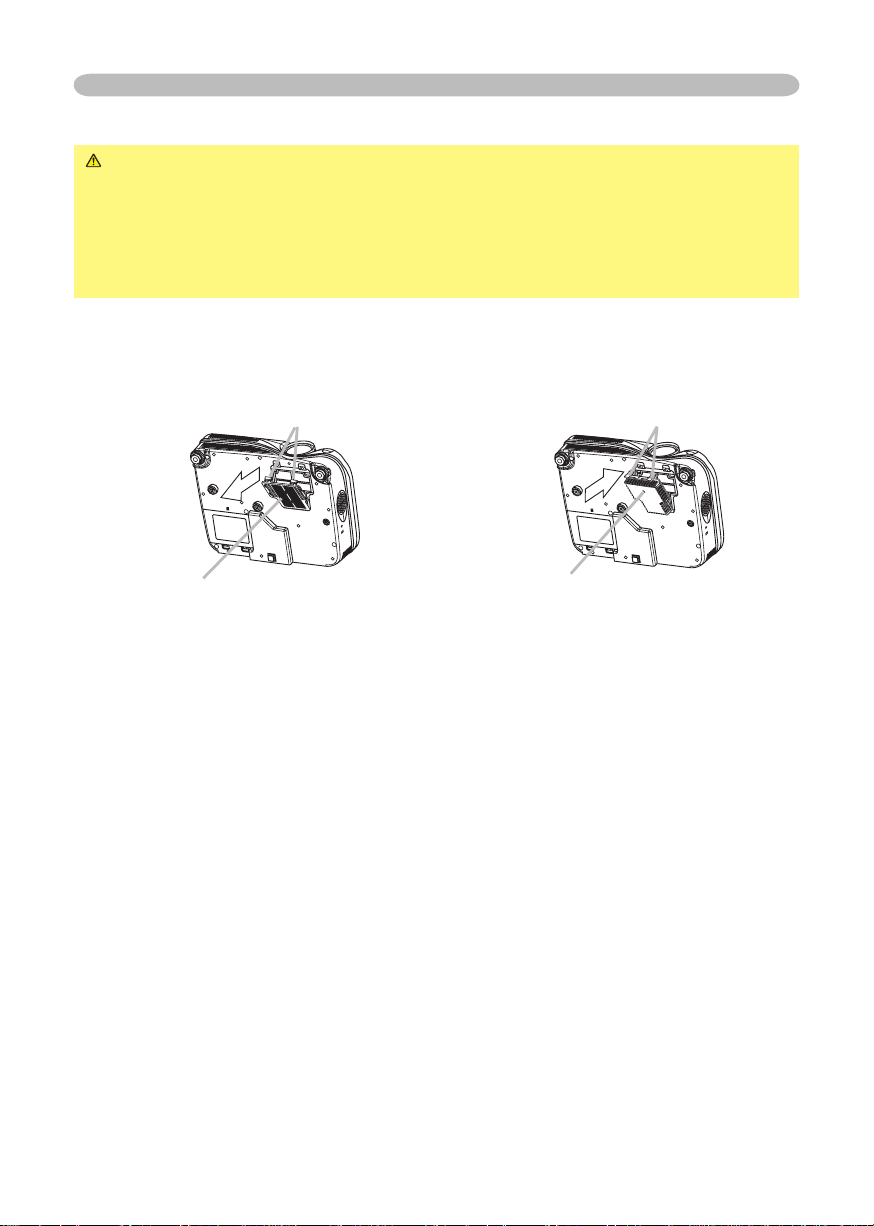
About the fi lter cover for bottom-up use
WARNING
the power switch is off and the power cord is not plugged in, then wait at least
45 minutes.
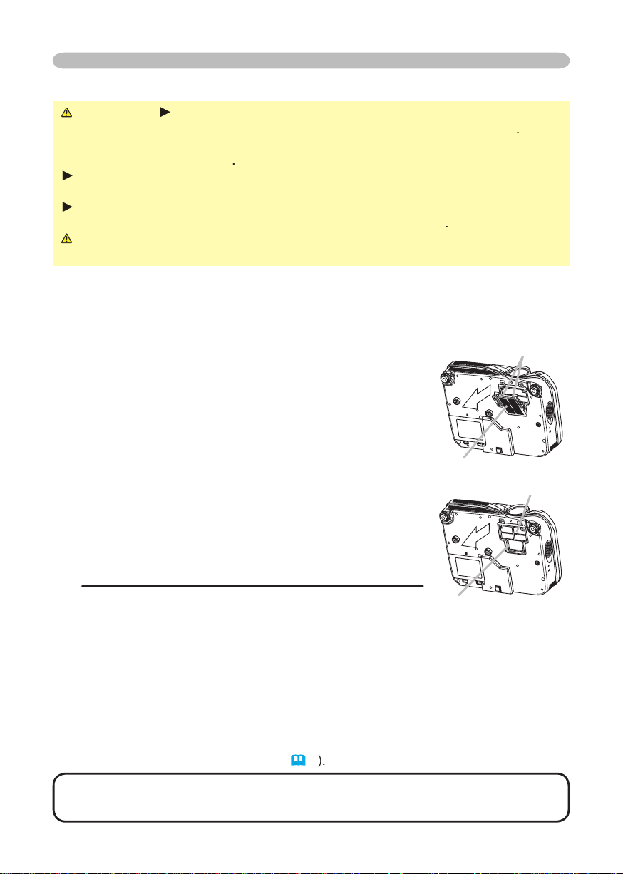
When the projector is installed bottom up, please use the accessory fi lter cover
for bottom-up use. It is higher than usual fi lter cover, to keep the space for intake
ventilation. Please change the fi lter cover in the following procedure.
After making sure that the projector is cool adequately,
To set
To remove
Page 12
Setting up
Attempting to connect a live device to the projector may generate extremely
to the device and/or projector
•
Whenever attempting to connect a laptop computer to the projector, be sure
to activate the laptop’s RGB external image output (set the laptop to CRT display or to
simultaneous LCD and CRT display). For details on how this is done, please refer
to the
on Windows. Then the resolution will go back to the original. It might be recommended
to use other CRT or LCD monitors to change the resolution.
About Plug-and-Play capability
2B. Plug-and-Play can be achieved by connecting this projector to a computer is VESA
type of connection is attempted.
Page 13
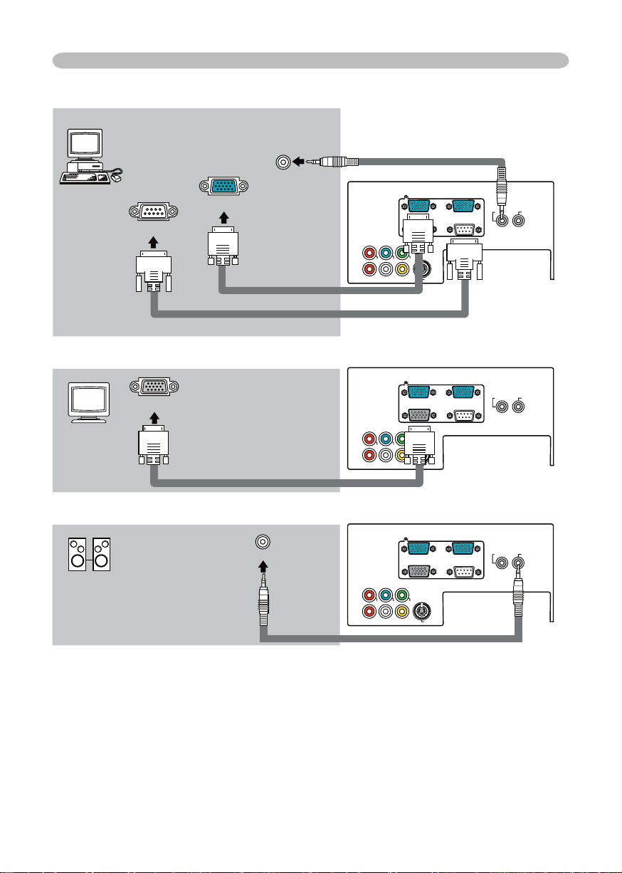
Setting up
Y
VIDEO
RGB IN1 RGB IN2
RGB OUT CONTROL
AUDIO 1-IN
S-VIDE
O
COMPONENT VIDEO
CB/P
B
CR/P
R
R-AUDIO 2-L
AUDIO-OU
T
Y
VIDEO
RGB IN1 RGB IN2
RGB OUT CONTROL
AUDIO 1-IN
S-VIDE
O
COMPONENT VIDEO
CB/P
B
CR/P
R
R-AUDIO 2-L
AUDIO-OU
T
Y
VIDEO
RGB IN1 RGB IN2
RGB OUT CONTROL
AUDIO 1-IN
S-VIDE
O
COMPONENT VIDEO
CB/P
B
CR/P
R
R-AUDIO 2-L
AUDIO-OU
T
RGB IN2
RGB OUT
Audio out
Audio in
* For the audio input, please refer to
the AUDIO item in the SETUP menu.
Page 14
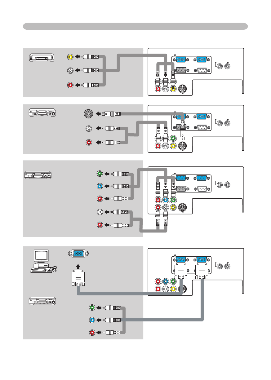
Y
VIDEO
RGB IN1 RGB IN2
RGB OUT CONTROL
AUDIO 1-IN
S-VIDE
O
COMPONENT VIDE
O
CB/P
B
CR/PR
R-AUDIO 2-L
AUDIO-OU
T
Y
VIDEO
RGB IN1 RGB IN2
RGB OUT CONTROL
AUDIO 1-IN
S-VIDE
O
COMPONENT VIDE
O
CB/PB
CR/PR
R-AUDIO 2-L
AUDIO-OU
T
Y
VIDEO
RGB IN1 RGB IN2
RGB OUT CONTROL
AUDIO 1-IN
S-VIDE
O
COMPONENT VIDE
O
CB/P
B
CR/PR
R-AUDIO 2-L
AUDIO-OU
T
Y
VIDEO
RGB IN1 RGB IN2
RGB OUT CONTROL
AUDIO 1-IN
S-VIDE
O
COMPONENT VIDE
O
CB/PB
CR/PR
R-AUDIO 2-L
AUDIO-OU
T
Setting up
Audio (L) out
Video out
Audio cable
Audio/Video cable
Audio (L) out
Audio (L) out
Y
/P
/P
Audio cable
Audio (R) out
Audio (R) out
/P
/P
Audio (R) out
Page 15
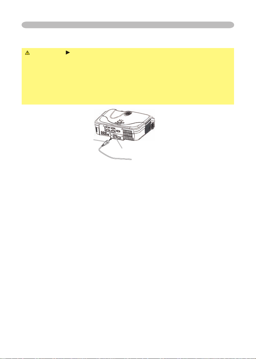
Setting up
WARNING
your dealer to newly get correct one.
AC inlet
of the power cord
Page 16
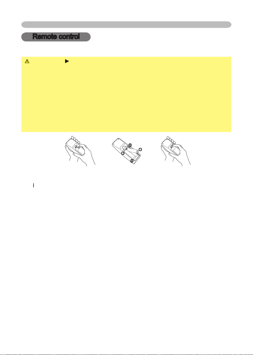
WARNING
Always handle the batteries with care and use them only as
which could result in fi re, injury and/or pollution of the surrounding environment.
types at the same time. Do not mix a new battery with used one.
Align and insert the two AA batteries according to their plus and minus
terminals as indicated in the remote control.
Remote control
Remote control
Page 17
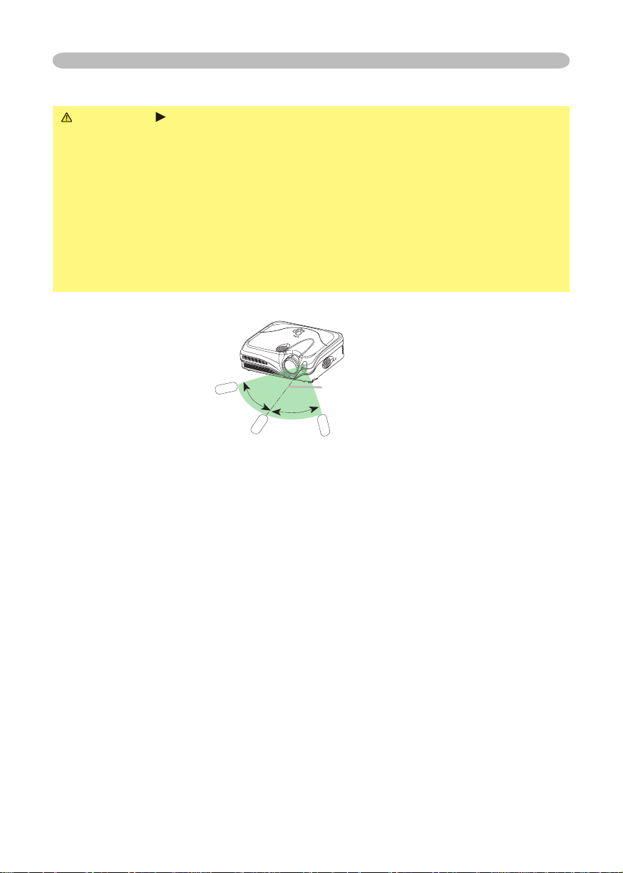
you won’t be using the remote control for an extended period.
The remote control works with the projector’s remote sensor.
to the left and right of the remote sensor).
to send a remote signal to the sensor directly, please try to use the refl ected signal.
that could block the remote control’s output signal to the projector.
Remote control
Page 18
Power on/off
Power on/off
WARNING
When the power is on, a strong light is emitted. Do not look into
the lens of projector. Also do not peep at the inside of projector through a hole.
Turn the power on/off in right order. Please power on the projector prior
to the connected devices. Power off the projector later than the connected devices.
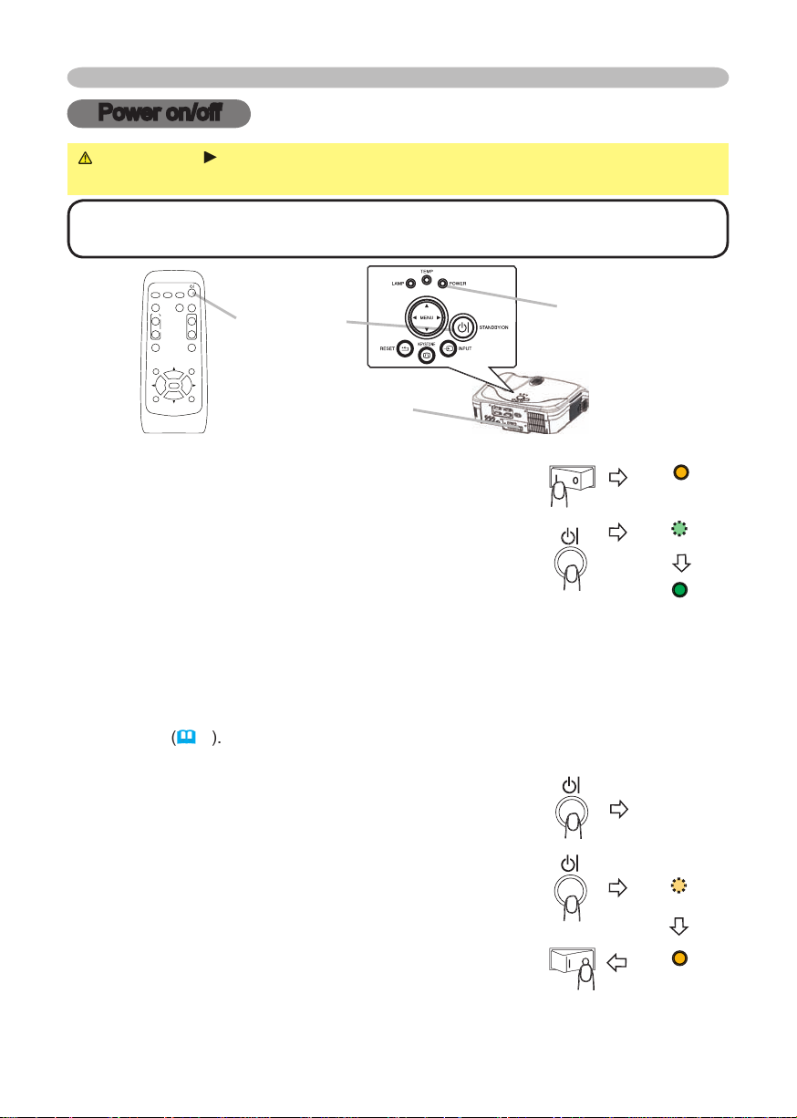
Turning on the power
the ON position.
The power indicator will light up in steady orange. Then
wait several seconds because the buttons may not
function for these several seconds.
The projector lamp will light up and the POWER indicator will begin blinking
To display the picture, select an input signal according to the section "Selecting an
Turning off the power
The message "Power off?" will appear on the screen for
The projector lamp will go off, and the POWER indicator
will begin blinking in orange.
Then the POWER indicator will stop blinking and light in
switch to the OFF position. The POWER indicator will go off. Attach the lens cover.
VIDEO
RG
B
SEARC
H
FREEZE
OFF
ON
MAGNIFY
ASPECT AUTO
BLAN
K
MUTE
VOLUME
KEYSTONE
POSITION
ES
C
ENTE
R
MENU
RESE
T
Page 19
Operating
Operating
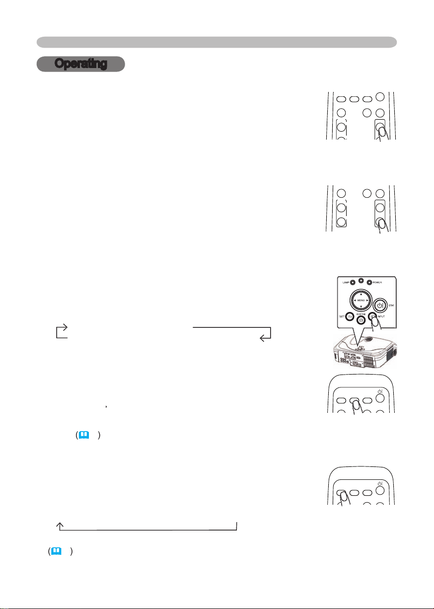
Adjusting the volume
A dialog will appear on the screen to aid you in adjusting the
volume.
To close the dialog and complete the operation, press the VOLUME button
Temporarily muting the sound
A dialog will appear on the screen indicating that you have
To restore the sound, press the MUTE or VOLUME button. Even if you don’t do
RGB IN1
RGB IN2
VIDEO
S-VIDEO
COMPONENT VIDEO
RGB IN2
RGB IN2
S-VIDEO
VIDEO
VIDEO
RG
B
SEARC
H
OFF
ON
MAGNIFY
ASPECT AUTO
BLAN
K
MUTE
VOLUME
VIDEO
RG
B
SEARC
H
FREEZE
OFF
ON
MAGNIFY
ASPECT AUTO
BLAN
K
MUTE
VOLUME
KEYSTONE
VIDEO
RG
B
SEARC
H
ASPECT AUTO
BLAN
K
VIDEO
RG
B
SEARC
H
ASPECT AUTO
BLAN
K
Page 20
Operating
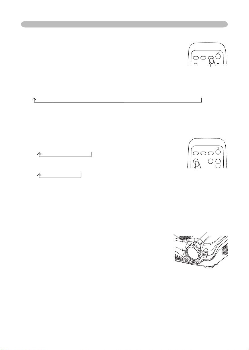
Adjusting the zoom and focus
4:3
16:9
4:3
16:9
SMALL
VIDEO input, only 16:9 mode can be selected.
VIDEO
RG
B
SEARC
H
MAGNIFY
ASPECT AUTO
BLAN
K
VOLUME
Zoom knob
The projector will start to check its input ports in order to
fi nd any input signals.
Then when an input is found, the projector will stop
the projector will return to the state selected before the
RGB IN 2
COMPONENT VIDEO
S-VIDEO
VIDEO
VIDEO
RG
B
SEARC
H
ASPECT AUTO
BLAN
K
Page 21
Operating
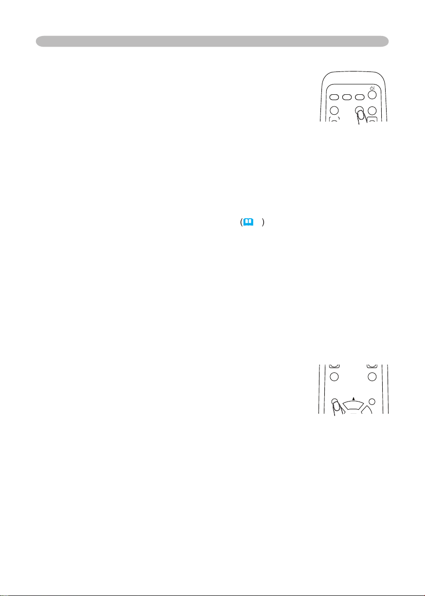
The vertical position, the horizontal position, the clock phase
And the aspect ratio will be automatically selected. Make sure that the
feature. A dark picture may still be incorrectly adjusted. Use a bright picture
when adjusting.
The video format
This function is available only when the AUTO mode is selected to the
VIDEO FORMAT item in the INPUT menu
function.
The vertical position and horizontal position will be automatically adjusted.
The aspect ratio will be automatically selected.
The clock phase will be automatically adjusted.
Adjusting the position
The “POSITION” indication will appear on the screen.
When you want to reset the operation, press the RESET button on the remote
To complete this operation, press the POSITION button again. Even if you don’t
VIDEO
RG
B
SEARC
H
FREEZE
OFF
ON
MAGNIFY
ASPECT AUTO
BLAN
K
MUTE
VOLUME
KEYSTONE
POSITION
ENTE
R
MENU
VIDEO
RG
B
SEARC
H
MAGNIFY
ASPECT AUTO
BLAN
K
VOLUME
Page 22
20
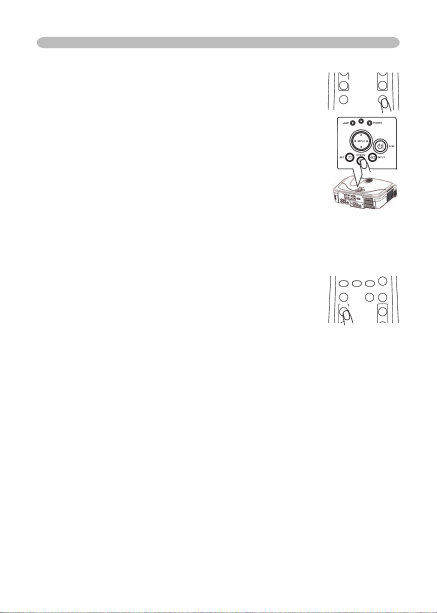
The “MAGNIFY” indication will appear on the screen
To move the zoom area, press the POSITION button in the MAGNIFY mode,
then use the cursor buttons ▲/▼/◄/► to move the area. And to fi nalize the
zoom area, press the POSITION button again.
To exit the MAGNIFY mode and restore the screen to normal, press the OFF
will be restored when the projector exits the MAGNIFY mode.
Operating
To close the dialog and complete this operation, press the
VIDEO
RG
B
SEARC
H
FREEZE
OFF
ON
MAGNIFY
ASPECT AUTO
BLAN
K
MUTE
VOLUME
KEYSTONE
VIDEO
RG
B
SEARC
H
ON
MAGNIFY
ASPECT AUTO
BLAN
K
MUTE
VOLUME
Page 23
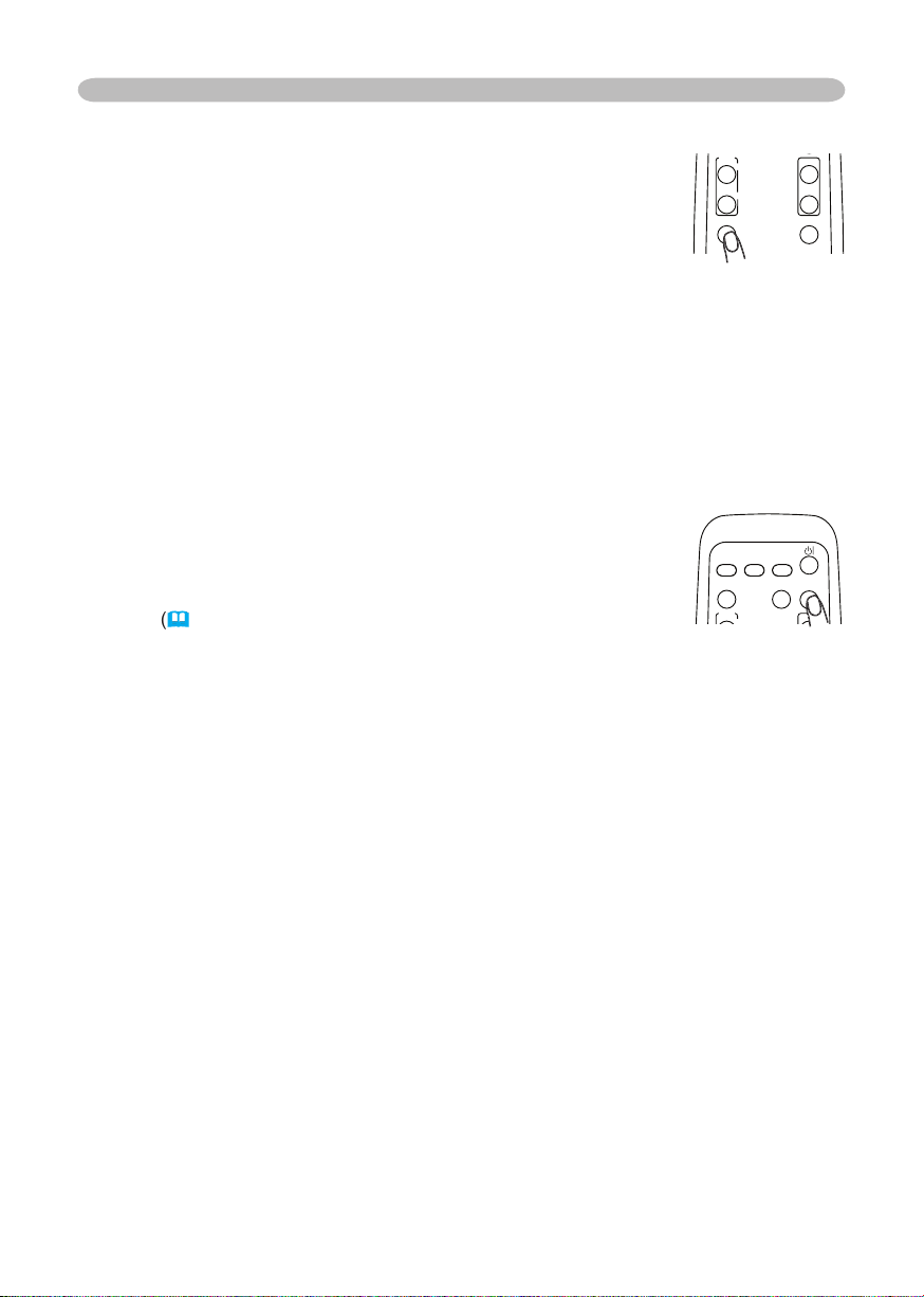
The “FREEZE” indication will appear on the screen, and the
To exit the FREEZE mode and restore the screen to normal,
too long.
Temporarily blanking the screen
The blank screen will be displayed instead of the screen of
To exit the blank screen and return to the input signal screen, press the
signal is changed, or when one of the projector’s buttons or the remote control
Operating
VIDEO
RG
B
SEARC
H
FREEZE
OFF
ON
MAGNIFY
ASPECT AUTO
BLAN
K
MUTE
VOLUME
KEYSTONE
VIDEO
RG
B
SEARC
H
MAGNIFY
ASPECT AUTO
BLAN
K
VOLUME
Page 24
VIDEO
RG
B
SEARC
H
FREEZE
OFF
ON
MAGNIFY
ASPECT AUTO
BLAN
K
MUTE
VOLUME
KEYSTONE
POSITION
ES
C
ENTE
R
MENU
RESE
T
VIDEO
RG
B
SEARC
H
FREEZE
OFF
ON
MAGNIFY
ASPECT AUTO
BLAN
K
MUTE
VOLUME
KEYSTONE
POSITION
ES
C
ENTE
R
MENU
RESE
T
Operating
Multifunctional settings
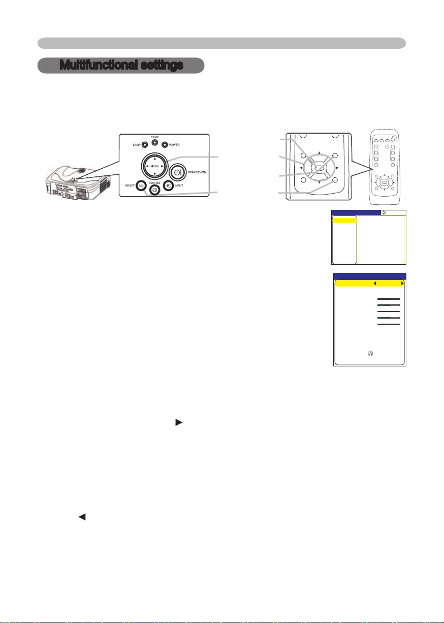
This projector has the following menus: PICTURE, IMAGE, INPUT, SETUP, SCREEN,
The basic operations of these menus are as follows.
the cursor buttons on the projector.
The Advanced MENU or EASY MENU will appear.
4.
Then press the cursor button ► on the projector or remote
Then press the cursor button
on the projector or remote control, or the ENTER button
on the remote control to progress. The operation menu of the selected item will appear.
4.
When you want to reset the operation, press the RESET button on the remote
simultaneously with operation (ex. LANGUAGE, H PHASE etc.) cannot be reset.
on the projector or remote control, or the ESC button on the remote control.
when a certain input signal is displayed.
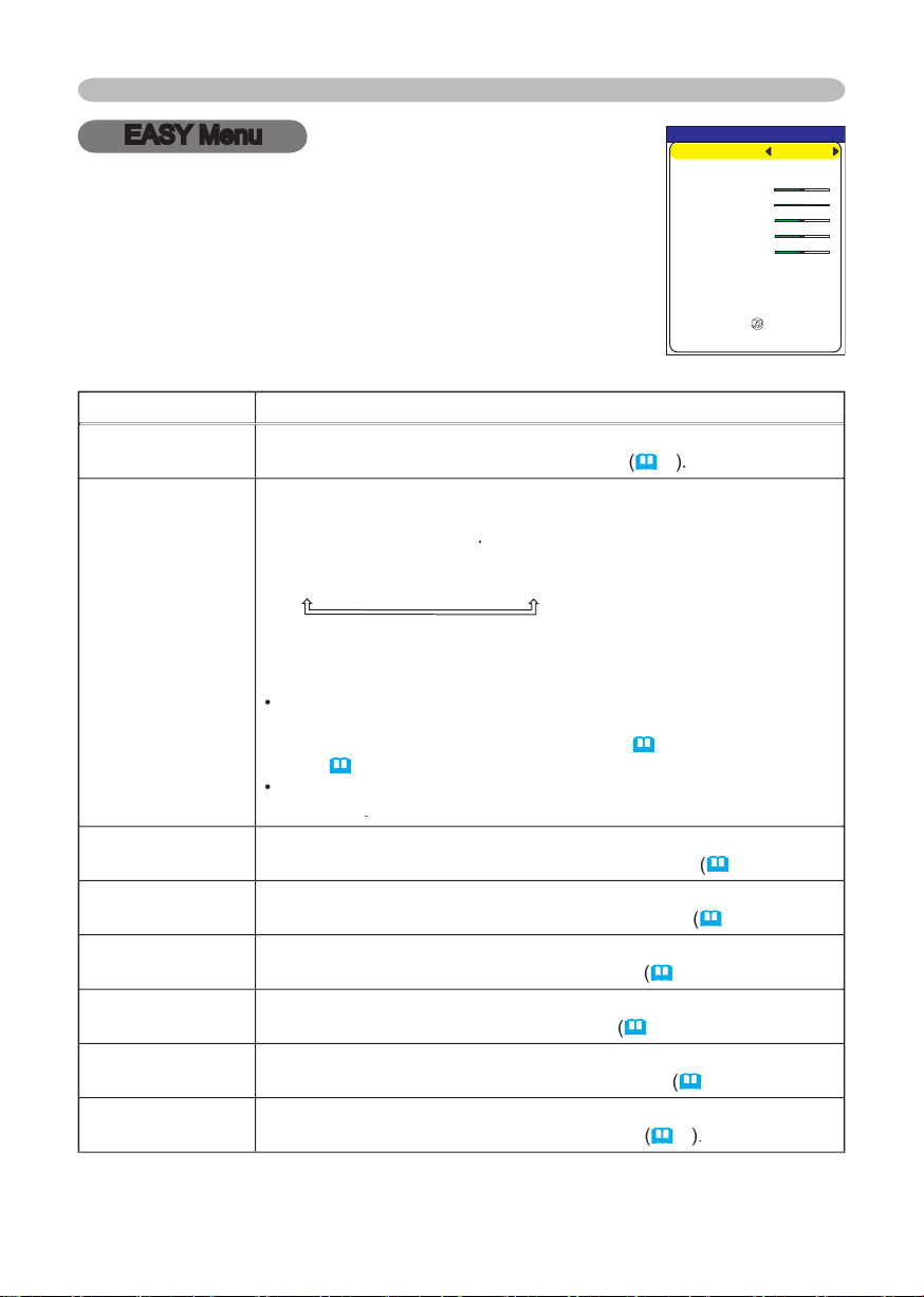
EASY MENU
CONTRAST
ASPECT 4:3
BRIGHTNESS
MODE NORMAL
COLOR
+0
+0
+0
TINT
+0
SHARPNESS
+3
WHISPER NORMAL
RESET
FILTER TIME 0
LANGUAGE ENGLISH
Go To Advance Menu...
MIRROR NORMAL
MENU [RGB]
IMAGE
SETUP
PICTURE
INPUT
OPTION
SCREEN
SHARPNESS +0
BRIGHTNESS +0
CONTRAST +0
COLOR +0
TINT +0
COLOR TEMP 6500K
GAMMA DEFAULT 1
MY MEMORY SAVE 1
:SELECT
EASY MENU
PROGRESSIVE TURN OFF
Page 25
23
Multifunctional settings
EASY Menu
ASPECT
of picture type. The
CINEMA
When the combination of GAMMA and COLOR TEMP differs from
TEMP (
PICTURE menu.
in the
menu
of section
menu
menu
TINT
TINT item in the
menu
menu
WHISPER
WHISPER item in the
menu
With the EASY MENU, items shown in the table below can
following table.
EASY MENU
CONTRAST
ASPECT 4:3
BRIGHTNESS
MODE NORMAL
COLOR
+0
+0
+0
TINT
+0
SHARPNESS
+3
WHISPER NORMAL
RESET
FILTER TIME 0
LANGUAGE ENGLISH
Go To Advance Menu...
MIRROR NORMAL
Page 26
Multifunctional settings
menu
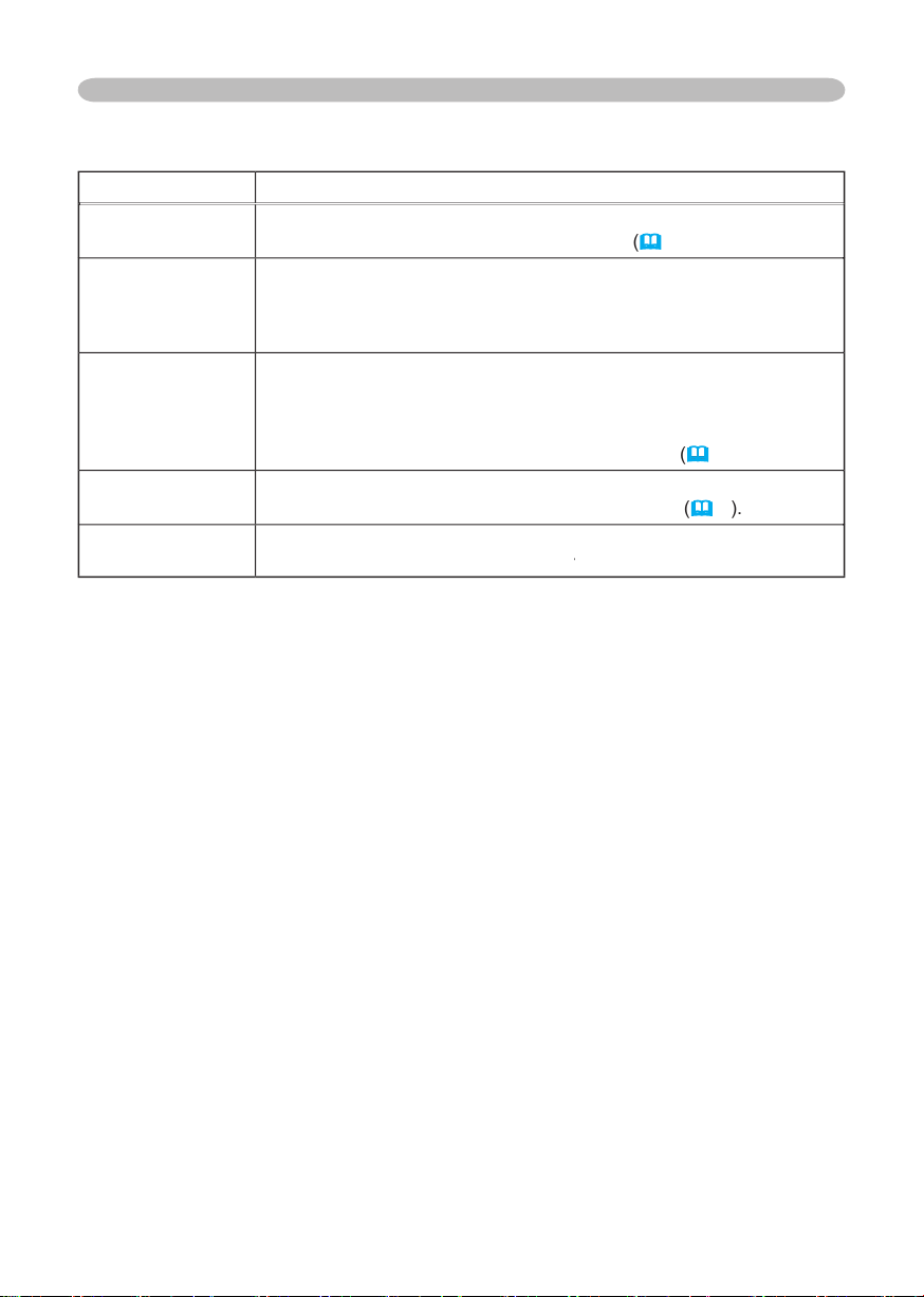
A dialog is displayed for confi rmation. Selecting RESET using the
of the air fi lter.
A dialog is displayed for confi rmation. Selecting RESET using the
menu
to toggle the menu language.
description of
in the
menu
Advanced Menu
or
OPTION.
Page 27
25
Multifunctional settings
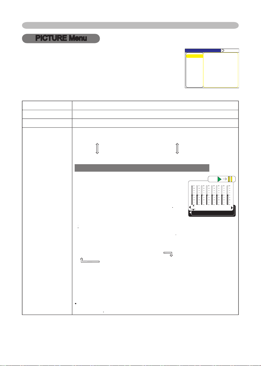
PICTURE Menu
: Light
Dark
Weak
ons ▲/▼ switches the
#1 DEFAULT
#1 CUSTOM
#2 DEFAULT
#3 CUSTOM
#3 DEFAULT
#2 CUSTOM
To adjust #1 CUSTOM, #2 CUSTOM or #3 CUSTOM
or the ENTER button
displays a dialog to aid you in adjusting the
This function is useful when you want to
using the buttons ◄/►, and
Y
ou can display a test pattern for checking the effect of your
No pattern
Gray scale of 9 steps
Ramp
Gray scale of 15 steps
The eight equalizing bars correspond to eight tone levels of the
test pattern except the darkest in the left end. If you want to adjust
the 2nd tone from left end on the test pattern, use the equalizing
When this fun
With the PICTURE menu, the items shown in the table
1
+0
2
+0
3
+0
4
+0
5
+0
6
+0
7
+0
8
+0
GAMMA [CUSTOM 1
]
ENTER :
MENU [RGB]
IMAGE
SETUP
PICTURE
INPUT
OPTION
SCREEN
SHARPNESS +0
BRIGHTNESS +0
CONTRAST +0
COLOR +0
TINT +0
COLOR TEMP 6500K
GAMMA DEFAULT 1
MY MEMORY SAVE 1
:SELECT
EASY MENU
PROGRESSIVE TURN OFF
Page 28
26
Multifunctional settings
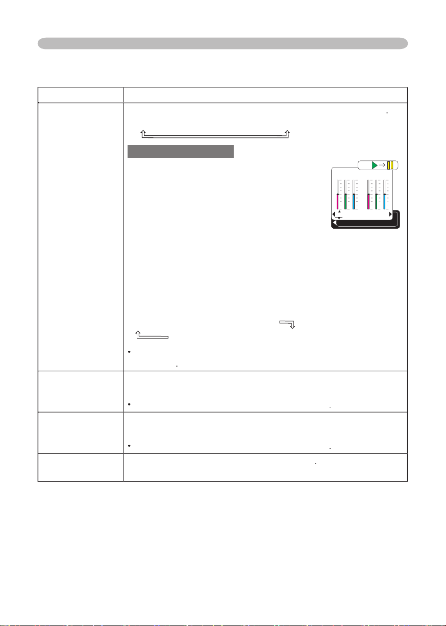
LOW
CUSTOM
To adjust CUSTOM
the
CUSTOM and then pressing the
displays
dialog
to aid you in adjusting the OFFSET and/or GAIN
of the CUSTOM mode.
on the whole tones of the test pattern.
on the brighter tones of the test pattern.
the buttons ▲/▼.
You can display a test pattern for checking the effect of your
No pattern
Gray scale of 9 steps
Ramp
Gray scale of 15 steps
Whe
strength of whole color.
Weak
This item can be selected only for a video signal
tint.
Red
This item can be selected only for a video signal
sharpness
Weak
R
+0
G
+0
B
+0
COLOR TEMP
ENTER :
OFFSET
R
+0
G
+0
B
+0
GAIN
Page 29
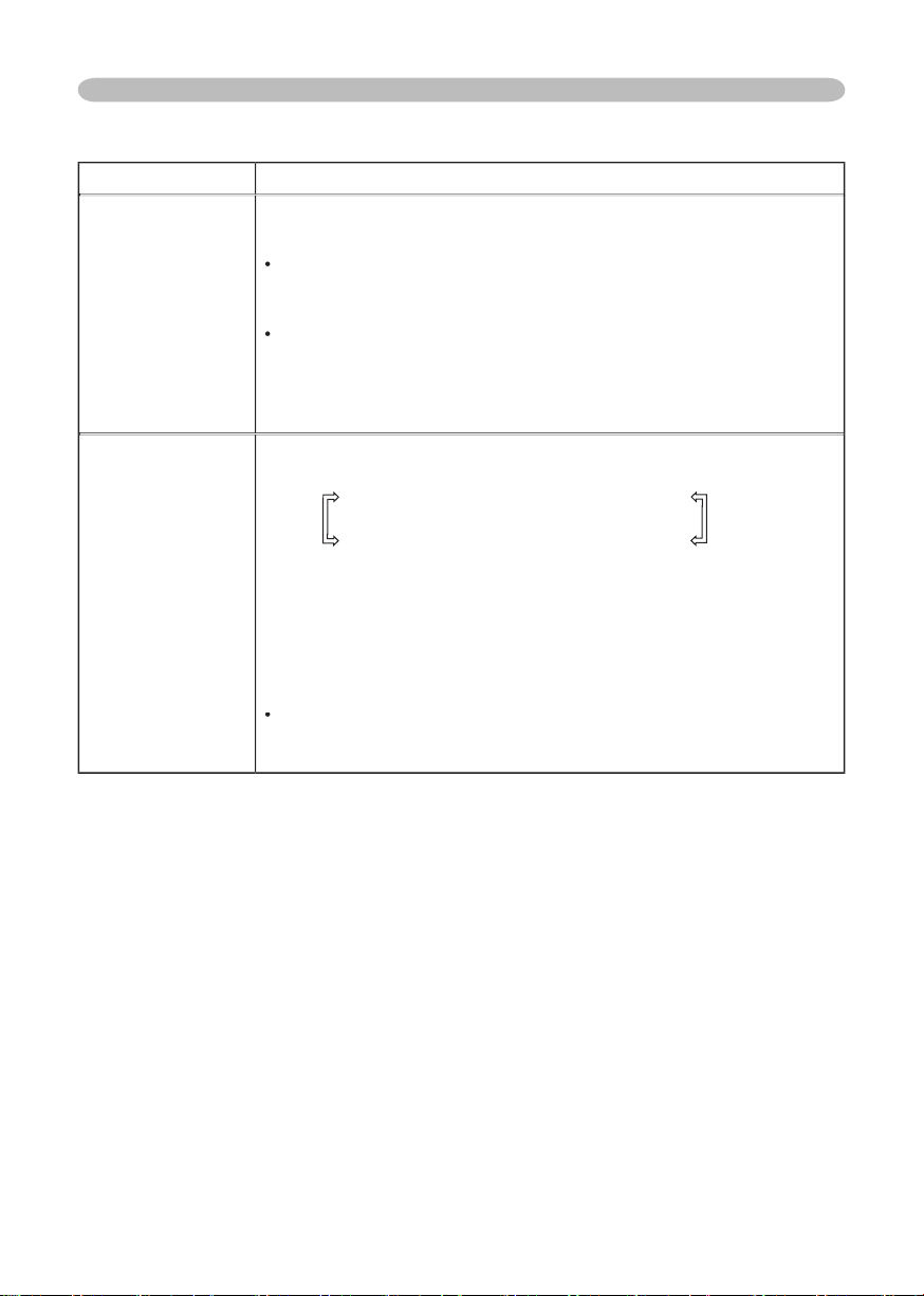
Multifunctional settings
TURN OFF
This function is performed only for an interlaced signal of a VIDEO
When TV or FILM is selected, the screen image will be sharp.
for a quick moving object. In such a case, please select TURN OFF,
LOAD2
LOAD3
LOAD4
SAVE2
SAVE1
This projector has 4 numbered memories for adjustment data.
the memory whose number corresponds to the c
ommand’s
number,
The current
adjustment data of the items in the PICTURE menu is
stored, except for the adjustment data in the CUSTOM modes for
the GAMMA and COLOR TEMP items.
Page 30
28
Multifunctional settings
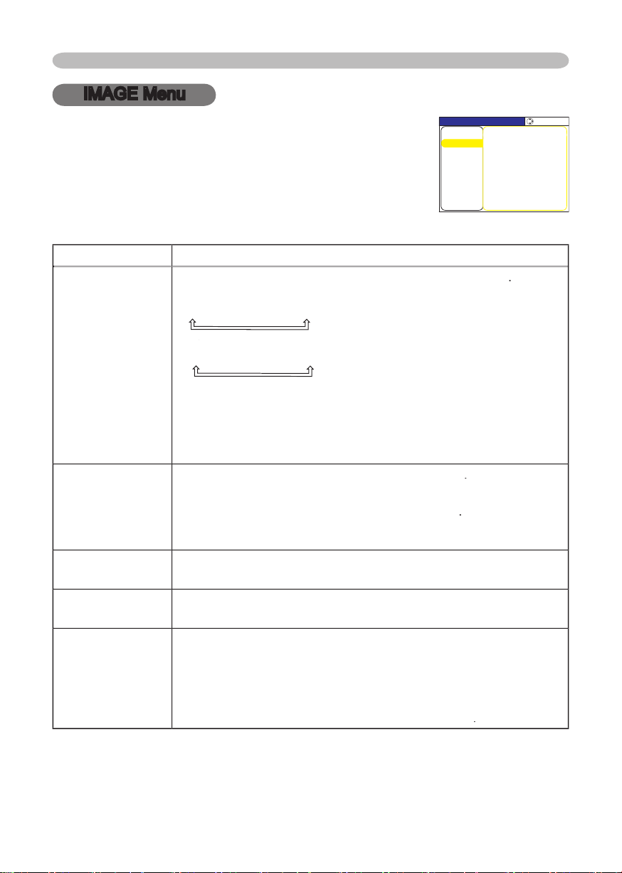
IMAGE Menu
ASPECT
4:3
16:9
NORMAL
a
video signal / no signal
4:3
16:9
SMALL
The NORMAL mode keeps the original aspect ratio of the signal.
HDTV signal of 1125i (1080i)
or 750p (720p)
as the
this item can't be selected.
setting.
over-scan ratio
Small (It magnifi es picture)
This item can be selected only for a video signal
When this adjustment is too large, certain degradation may appear
V POSITION
Down
Right
fl icker.
Left
This item can be selected only for an RGB signal or a component
video signal.
video port
With the IMAGE menu, items shown in the table below can
MENU [RGB]
IMAGE
PICTURE
:SELECT
AUTO ADJUST EXECUTE
ASPECT 4:3
OVER SCAN 5
H PHASE 16
H SIZE 1344
H POSITION 142
V POSITION 25
SETUP
INPUT
OPTION
EASY MENU
SCREEN
Page 31

29
Multifunctional settings
This item can be selected only for an RGB signal
When this adjustment is excessive, the picture may not be
displayed correctly. In such a case, please reset the adjustment
operation.
AUTO ADJUST
RGB signal
The vertical position, the horizontal position, the clock phase and
the horizontal size will be automatically adjusted. And the aspect
a
video signal or s-video signal
The video format best suited for the respective input signal will be
selected automatically.
This function is available only when the AUTO mode is selected to
the VIDEO FORMAT item in the INPUT menu. For a component
video signal, the signal type is identifi ed automatically independently
of this function.
The vertical position and horizontal position will be automatically
The aspect ratio will be automatically selected.
The clock phase will be automatically adjusted.
The automatic adjustment operation requires approximately 10
seconds. Also please note that it may not function correctly with
some input.
Page 32
Multifunctional settings
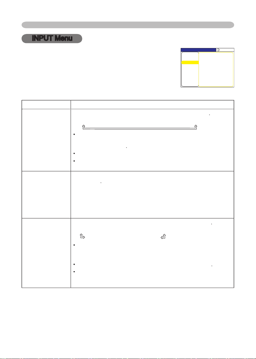
INPUT Menu
AUTO
RGB
SMPTE240
REC709
REC601
This item can be selected only for an RGB signal or a component
video signal
video port)
The AUTO mode automatically selects the optimum mode.
The AUTO operation may not work well at some signals. In such a
function of COMPONENT
VIDEO port
SCART RGB
When the SCART RGB is selected, the COMPONENT VIDEO port
function as a port for a SCART RGB signal input.
A SCART adapter
details, contact your dealer.
VIDEO FORMAT
t
AUTO
PAL
This item is performed only for a video signal from the VIDEO port
or the S-VIDEO port. For a component video signal, the signal type
The AUTO mode automatically selects the optimum mode
The AUTO operation may not work well for some signals. If the
With the INPUT menu, the items shown in the table below
MENU [RGB]
IMAGE
SETUP
PICTURE
INPUT
OPTION
EASY MENU
SCREEN
:SELECT
VIDEO FORMAT AUTO
COLOR SPACE AUTO
INFORMATION
COMPONENT COMPONENT
Page 33
Multifunctional settings
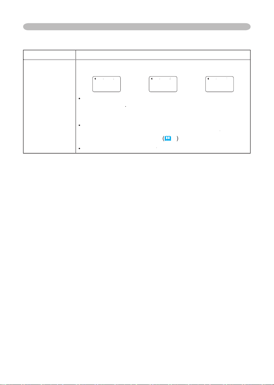
displays a dialog titled “INPUT INFORMATION”.
-INFORMA
TION
RGB
0
FRAME LOCK
-INFORMA
TION
S-VIDEO
SECAM
AUT
O
-INFORMA
TION
COMPONENT
576i @50
SCART RGB
The “FR
AME LOCK” message on the dialog means the frame lock
function is working
This function automatically works when a RGB
signal with vertical frequency of 50 to 60 Hz is input, and it displays
The “SCART RGB” message means the COMPONENT VIDEO
port. Please refer
to the
This item
for
no signal and sync out.
Page 34
Multifunctional settings
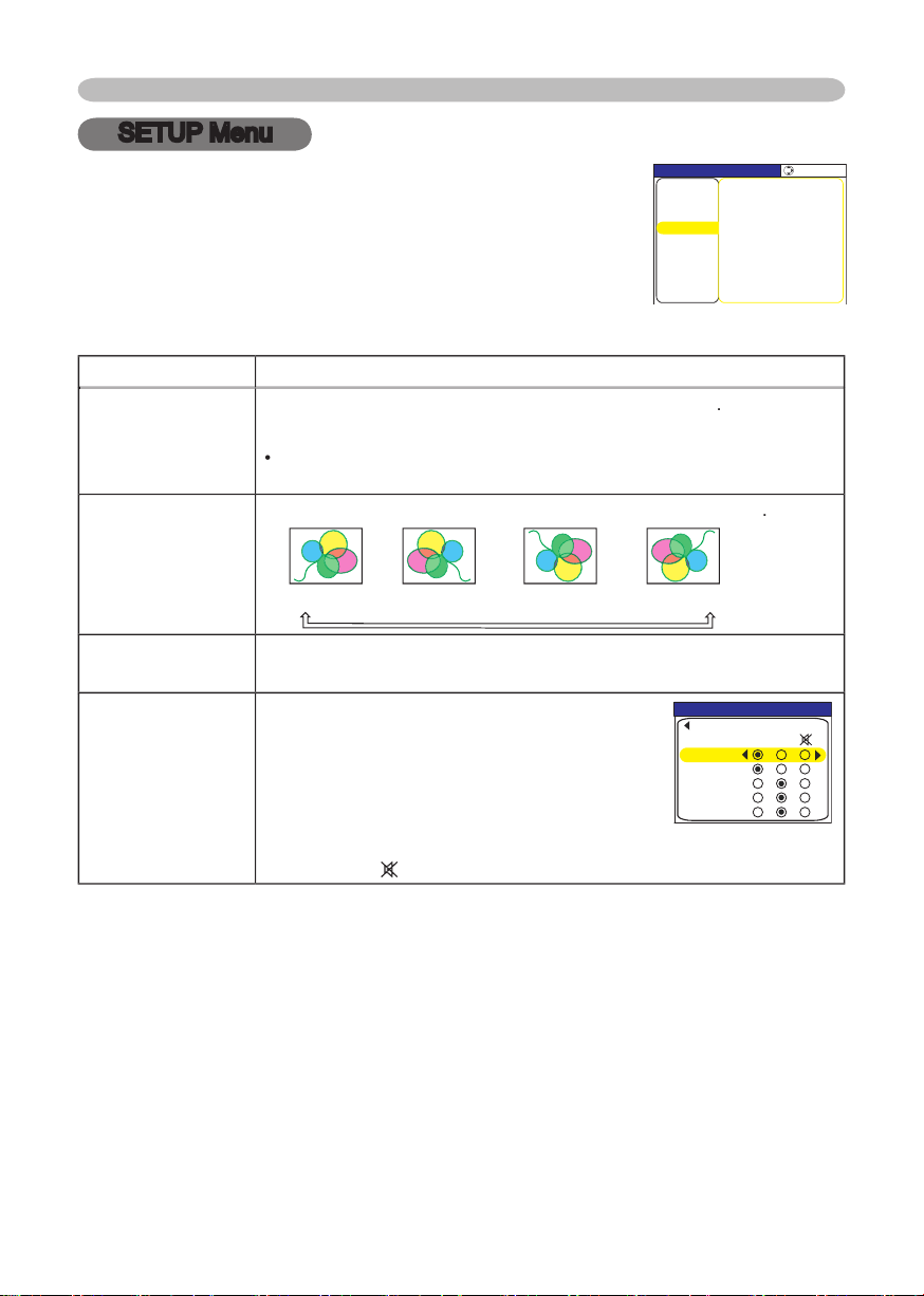
SETUP Menu
WHISPER
turns off/on the whisper mode
WHISPER
When the WHISPER is selected, acoustic noise and screen
H:INVERT
V:INVERT
H&V:INVERT
VOLUME
AUDIO
with the input port using the buttons
(2).
When off is selected, both of two audio ports
do not work for the input port.
RGB2
COMPONENT
S-VIDEO
VIDEO
2
With the SETUP menu, the items shown in the table below
MENU [RGB]
IMAGE
SETUP
PICTURE
INPUT
OPTION
EASY MENU
SCREEN
:SELECT
WHISPER NORMAL
MIRROR NORMAL
AUDIO
VOLUME 16
AUDIO
RGB2
QUIT
RGB1
S‑VIDEO
VIDEO
COMPONENT
1 2
Page 35
Multifunctional settings
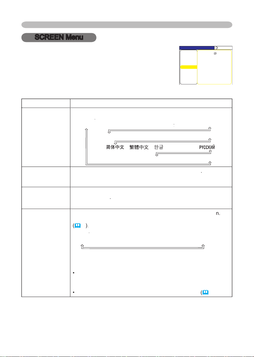
SCREEN Menu
POLSKI
TÜRKÇE
FRANÇAIS
DEUTSCH
ESP
AÑOL
I
TA
NEDERLANDS
POR
TUGUÊS
SVENSKA
To quit the operation, press the MENU button on the remote control
or keep no operation for 10 seconds.
DARK
The blank screen is a screen
for the temporarily blanking feature
ORIGINAL
To avoid remaining as an afterimage, the MyScreen and the
With the SCREEN menu, the items shown in the table
MENU [RGB]
IMAGE
SETUP
PICTURE
INPUT
OPTION
EASY MENU
SCREEN
:SELECT
LANGUAGE ENGLISH
MENU POSITION
START UP ORIGINAL
OSD BRIGHT. 5
MyScreen
MyScreen Lock TURN OFF
MESSAGE TURN ON
BLANK BLACK
Page 36
Multifunctional settings
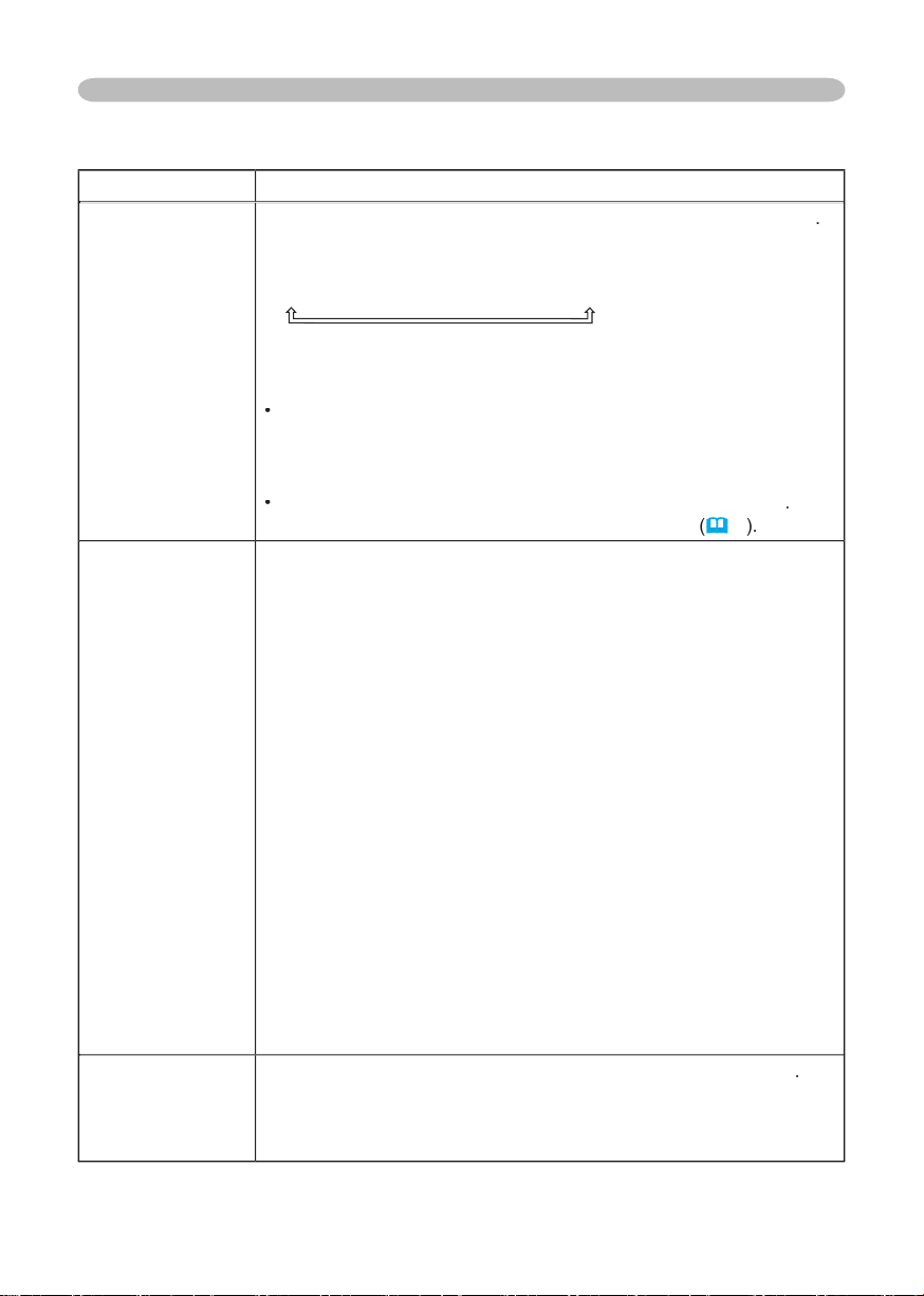
the
The start-up screen is a screen displayed when no signal or an
ORIGINAL
TURN OFF
To avoid remaining as an afterimage, the MyScreen and the
will change to the BLACK screen.
below
the BLANK screen,
item
This item functions for capturing the MyScreen of the blank screen
you if you start capturing the picture from the current screen.
the ENTER button on the remote control when the picture is
displayed. The picture will freeze and the frame for capturing
To stop performing, press the RESET or ESC button on the
2. Using the buttons ◄/►/▲/▼ adjusts the frame position. Please
To start registration, press the ENTER button on the remote
To restore the screen and return to the previous dialog, press the
several
minutes. When the registration is
turns on/off the MyScreen lock function
TURN ON
TURN OFF
When the TURN ON is selected, the item MyScreen is locked. Use
this function for protecting the current MyScreen.
Page 37
Multifunctional settings
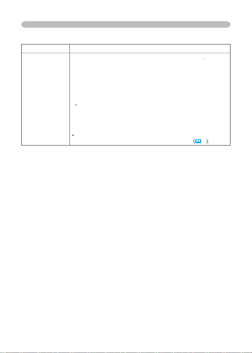
t
TURN ON
TURN OFF
When the TURN ON is selected, the following message function
works.
”NO INPUT IS DETECTED”
”SYNC IS OUT OF RANGE”
while searching for the input
The indication of the input signal displayed by changing
The indication of the aspect ration displayed by changing
The indication of
When the TURN OFF is selected
freezing for a malfurction
Page 38
Multifunctional settings
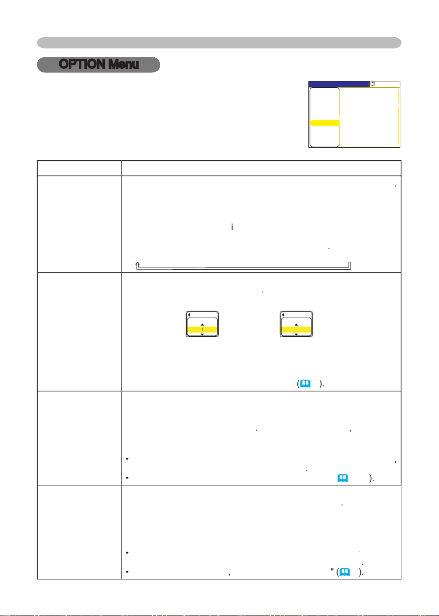
OPTION Menu
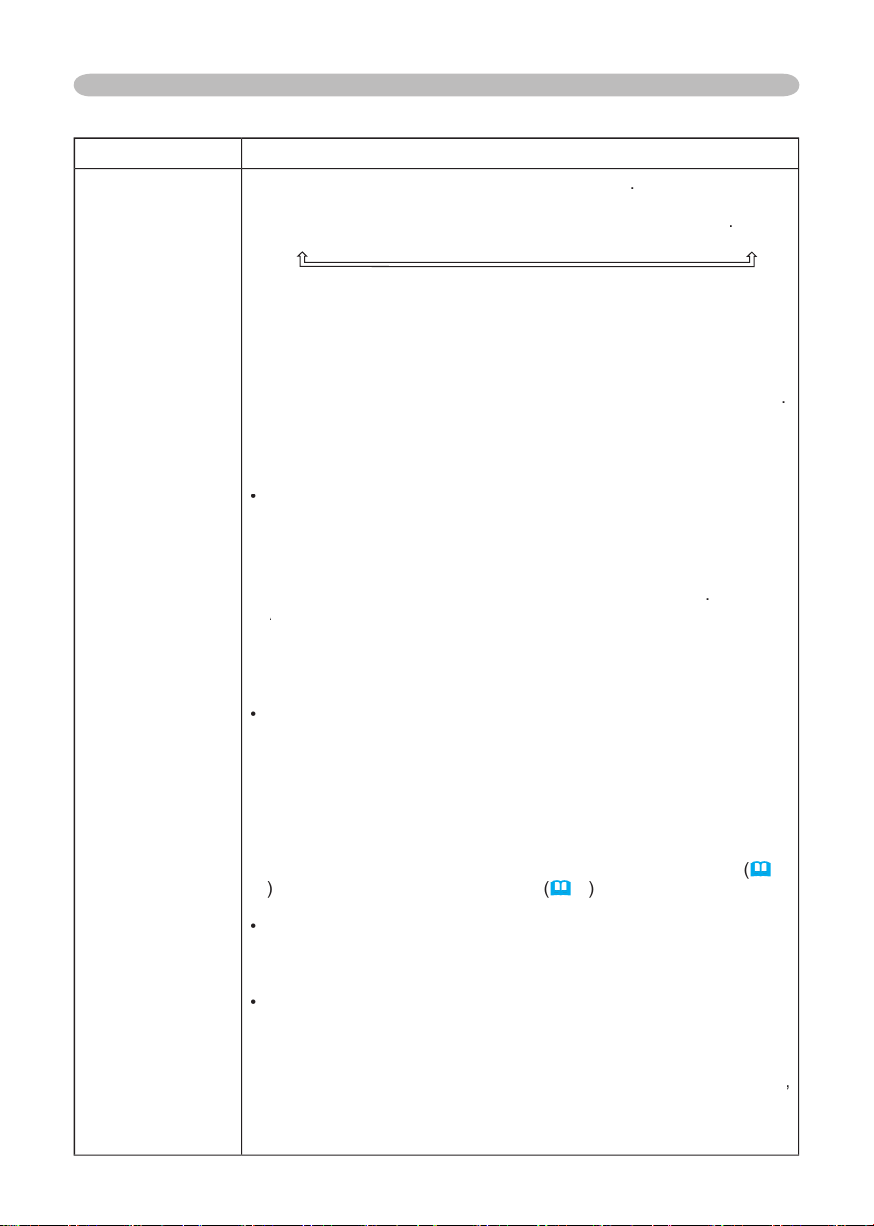
AUTO SEARCH
turns on/off the
automatic signal search
function
TURN ON
TURN OFF
This function works with INPUT, RGB, and VIDEO buttons.
When the TURN ON is selected, detecting no signal automatically
the following order
started from the current port.
Then
when an input is found, the
S-VIDEO
VIDEO
AUTO OFF
time to count down to
Short (min. 0 minute = DISABLE)
AUT
O OF
AUT
O OF
F
DISABLE
0
When the time is set to 0, the projector is not turned off automatically.
When the time is set to 1 to 99, and when the passed time with no-
signal or an unsuitable signal reaches at the set time, the projector
The lamp time is the time counted after the last resetting. It is
shown in the OPTION menu as the usage time of the lamp.
or the button
of the projector
displays
To reset the lamp time
select the
CANCEL
only when you have replaced the lamp
for a corresponding message about the lamp
the lamp
(
The
fi lter time
is the time counted after the last resetting. It is shown
time of the
or the button
of the projector
displays a dialog. To reset the fi lter time, select the
CANCEL
replaced
the
the
see the section "
Air fi lter
40
With the OPTION menu, the items shown in the table below can
or remote control, or the ENTER button on the remote control to
TIME. T
MENU [RGB]
PICTURE
:SELECT
IMAGE
SETUP
INPUT
OPTION
EASY MENU
SCREEN
AUTO OFF 0
LAMP TIME 0
FILTER TIME 0
AUTO SEARCH TURN OFF
SERVICE
Page 39
Multifunctional settings
the
the ENTER button on the remote control to
AUTO ADJUST
GHOST
otation speed of the cooling
fans. The HIGH is the mode for use at highlands etc.
AUTO ADJUST
the buttons ▲/▼
/disables
the
When DISABLE is selected, the automatic adjustment feature is
disabled, although rough adjustment is automatically performed
depending on the basic setting.
disable the automatic adjustment, and make adjustment manually.
2.
Adjust the selected element using the buttons ▲/▼ to disappear ghost.
Adjust the selected element using the buttons ▲/▼ to disappear ghost.
turns on/off the key lock feature. When TURN ON is
selected, the buttons on the projector except the STANDBY/ON button are locked.
TURN ON
TURN OFF
function does not have any effect on the remote control.
200h
300h
TURN OFF
50h
After selecting “50h”, 100h”, “200h”, or “300” , the message “CLEAN
THE AIR FILTER” will appear after the timer reaches the interval
time set by the menu. Please refer to the “FILTER TIME” item
and the table “Related message”
42
When the “TURN OFF” is chosen, the air-fi lter cleaning message will not appear.
with the operating environment of the projector and the condition of air
fi lter, especially when the “200h”, “300h” or “TURN OFF” is chosen.
all the items in all of menus will collectively return to the
ote
that the items LAMP TIME, FILTER TIME and LANGUAGE are not reset.
CANCEL
Page 40
Maintenance
Maintenance
WARNING
The projector uses a high-pressure mercury glass lamp. The lamp can
with a loud bang, or burn out
with a loud bang, or burn out
to fl y into the lamp housing, and for
to escape from the projector’s vent holes.
About disposal of a lamp
• This product contains a mercury lamp; do not
the US) or www.epsc.ca (in Canada).
the power cord from the outlet, and make sure to request a replacement
try to clean the projector or replace the lamp yourself.
ventilate the room well, and make sure not to breathe the gas that
Never unscrew except the appointed (marked by an arrow) screws.
the ceiling. This is dangerous, since if the lamp’s bulb has broken, the
that there are electrical problems elsewhere besides the lamp. If this
the section "Related Messages" and "Regarding the indicator Lamps"),
the plug
from the
outlet
Page 41
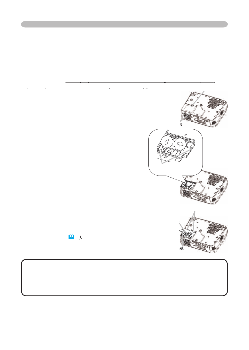
When the indicators or a message prompt you to replace the lamp, replace the
Turn the projector off, and unplug the power cord. Allow the lamp to cool for
To prepare a new lamp, contact your dealer and tell the lamp type number
456-8915.
After making sure that the projector has
the lamp, and slowly pick up the lamp by the
two screws that are loosened in the previous
While interlocking the 2 tabs of the lamp
the two claws to fi x the lamp cover.
facing up.
Turn the projector on, and reset the lamp
time using the LAMP TIME function in the
(
• When the lamp has been replaced after the message of "THE
Maintenance
of claws
Tabs
Page 42
40
Maintenance
When the indicators or a message prompts you to clean the air filter, clean the air filter
Turn the projector off, and unplug the power cord.
Allow the projector to cool for at least 45 minutes. And
After making sure that the projector is cool adequately,
the projector is placed lens-side up, hold the projector.
Apply a vacuum cleaner to the vent of the projector for the
Apply a vacuum cleaner to the air fi lter and the fi lter cover.
To prepare a new air fi lter, contact your dealer and tell the air
fi lter type number =
An air fi lter of specifi ed type will come even with a replacement lamp for this projector.
Turn the projector on, and reset the fi lter time using the FILTER TIME
function of the OPTION menu
(
WARNING
then allow
the projector to cool suffi ciently
The
Avoid wetting the projector or inserting liquids in the projector. It could result
Air fi lter
Air fi lter
Air fi lter’s knob
Page 43

Maintenance
WARNING
►Before caring, make sure the power switch is off and the
The care in a high temperature state of the projector could cause a burn and/or
following. Incorrect care could cause not only an injury but adverse infl uence
Turn the projector off, and unplug the power cord. Allow the projector to cool
suffi ciently.
After making sure that the projector is cool adequately, lightly wipe the lens
with a commercially available lens-cleaning wipe. Do not touch the lens
Turn the projector off, and unplug the power cord. Allow the projector to cool
suffi ciently.
After making sure that the projector is cool adequately, lightly wipe with gauze
Page 44
Troubleshooting
Troubleshooting
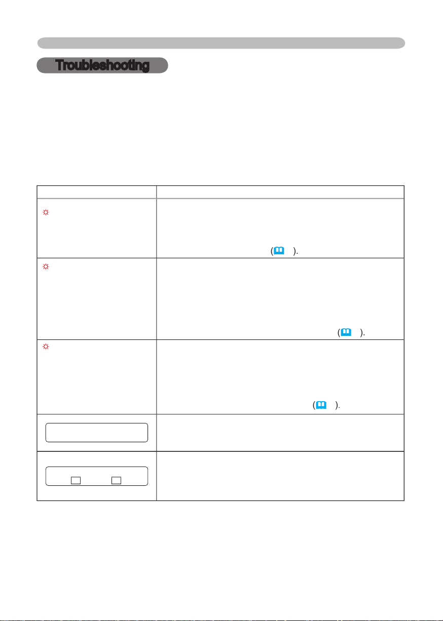
When the unit's power is on, messages such as those shown below may be
service company.
Although these messages will be automatically disappeared around several
CHANGE THE LAMP.
AFTER REPLACING LAMP,
RESET THE LAMP TIMER.
The time the lamp timer has counted is approaching
2000 hours.
sure to reset the lamp timer
CHANGE THE LAMP.
AFTER REPLACING LAMP,
RESET THE LAMP TIMER.
THE POWER WILL
BE
TURNED OFF ** hrs later.
The time the lamp timer has counted is approaching
2000 hours, so a lamp change within
**
hours is
When lamp usage reaches 2000 hours, the power will
CHANGE THE LAMP.
AFTER REPLACING LAMP,
RESET THE LAMP TIMER.
THE POWER WILL BE
TURNED OFF 0 hrs later.
As the time the lamp timer has counted has reached
2000 hours, the power will soon be automatically
turned off.
ON ***
There is no input signal.
of the signal source.
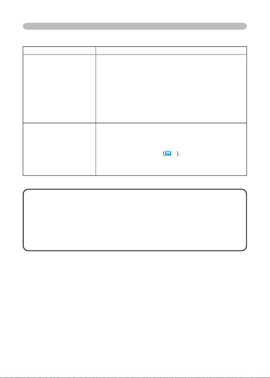
SYNC IS OUT OF RANGE
ON *** fH *****kHz fV *****Hz
The horizontal or vertical wavelength of the input signal
source specs.
Page 45
43
Troubleshooting
CHECK THE AIR FLOW
The internal temperature is rising.
down at least 20 minutes. After having confi rmed the
following items, please turn the power ON again.
•
•
set FAN SPEED of the SERVICE item in the OPTION menu
to HIGH.
REMINDER
*** HRS PASSED AFTER THE
LAST FILTER CHECK.
FILTER MAINTENANCE IS ESSENTIAL
TO REMOVE WARNING MESSAGE,
RESET FILTER TIMER.
SEE MANUAL FURTHER INFO.
A note of precaution when cleaning the air fi lter.
the air fi lter referring to the “Air Filter” section of this manual.
After you have cleaned or changed the air fi lter, please be
sure to reset the fi lter timer
40
• A lamp has a fi nite product life. Lamps are characterized by the
fact that, after long hours of usage, a lamp will no longer light up, or the lamp
will break or burst, etc. This projector is equipped with an automatic shut-down
function, such that the power will automatically be turned off when lamp usage
time has reached 2000 hours. Please be aware, however, that among lamp
types, there are major differences in product lifetimes; a lamp may thus fail to
Page 46
Troubleshooting
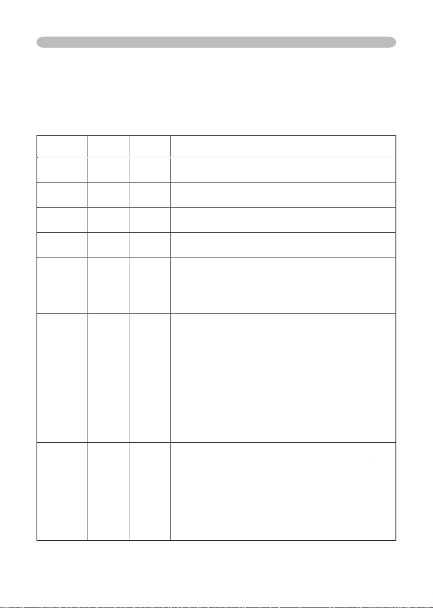
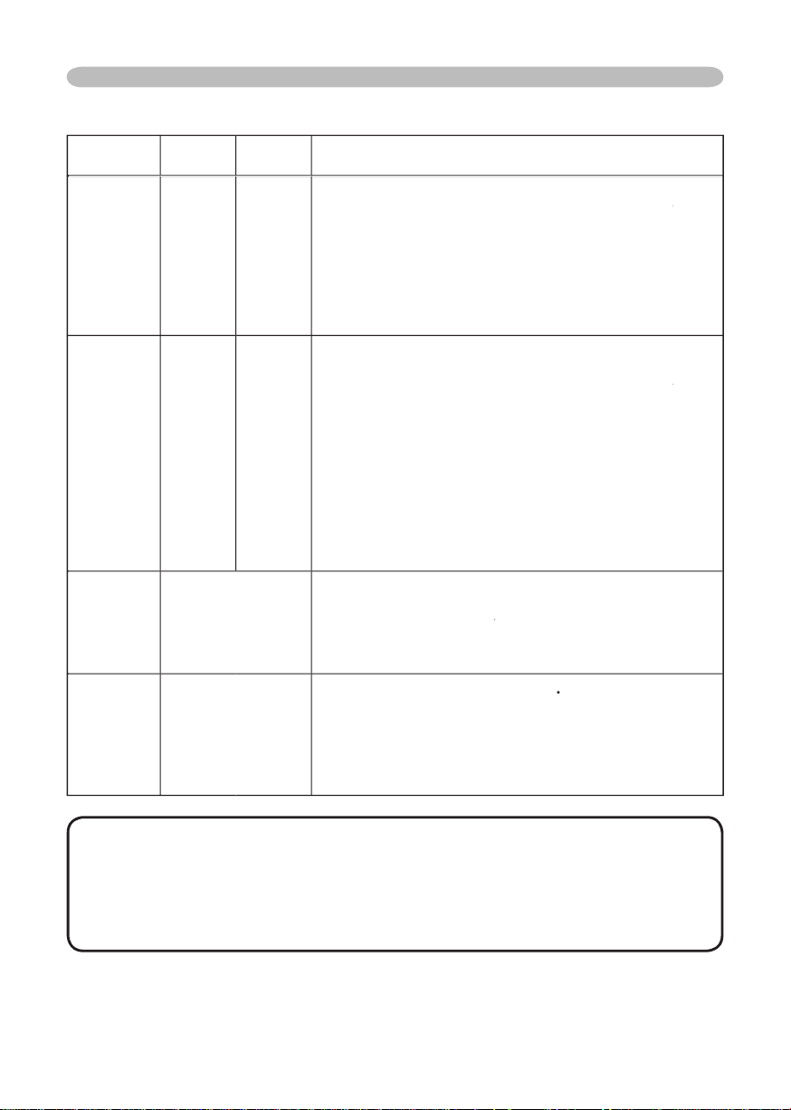
TEMP
Orange
Turned
Turned
The projector is in a standby state.
Green
Turned
Turned
The projector is warming up.
Green
Turned
Turned
The projector is in an on state.
Orange
Turned
Turned
The projector is cooling down.
Red
tionary)
tionary)
The projector is cooling down. A certain error
the item descriptions below.
Red
Red
Red
Turned
The lamp does not light, and there is a
suffi ciently cooled down, please make confi rmation of
the following items, and then turn the power on again.
Red
Red
Red
Turned
The lamp cover has not been properly fi xed.
to
After the projector has
suffi ciently cooled down, please make confi rmation
of the attachment state
of the lamp cover.
After
on again.
the
Page 47
45
Troubleshooting
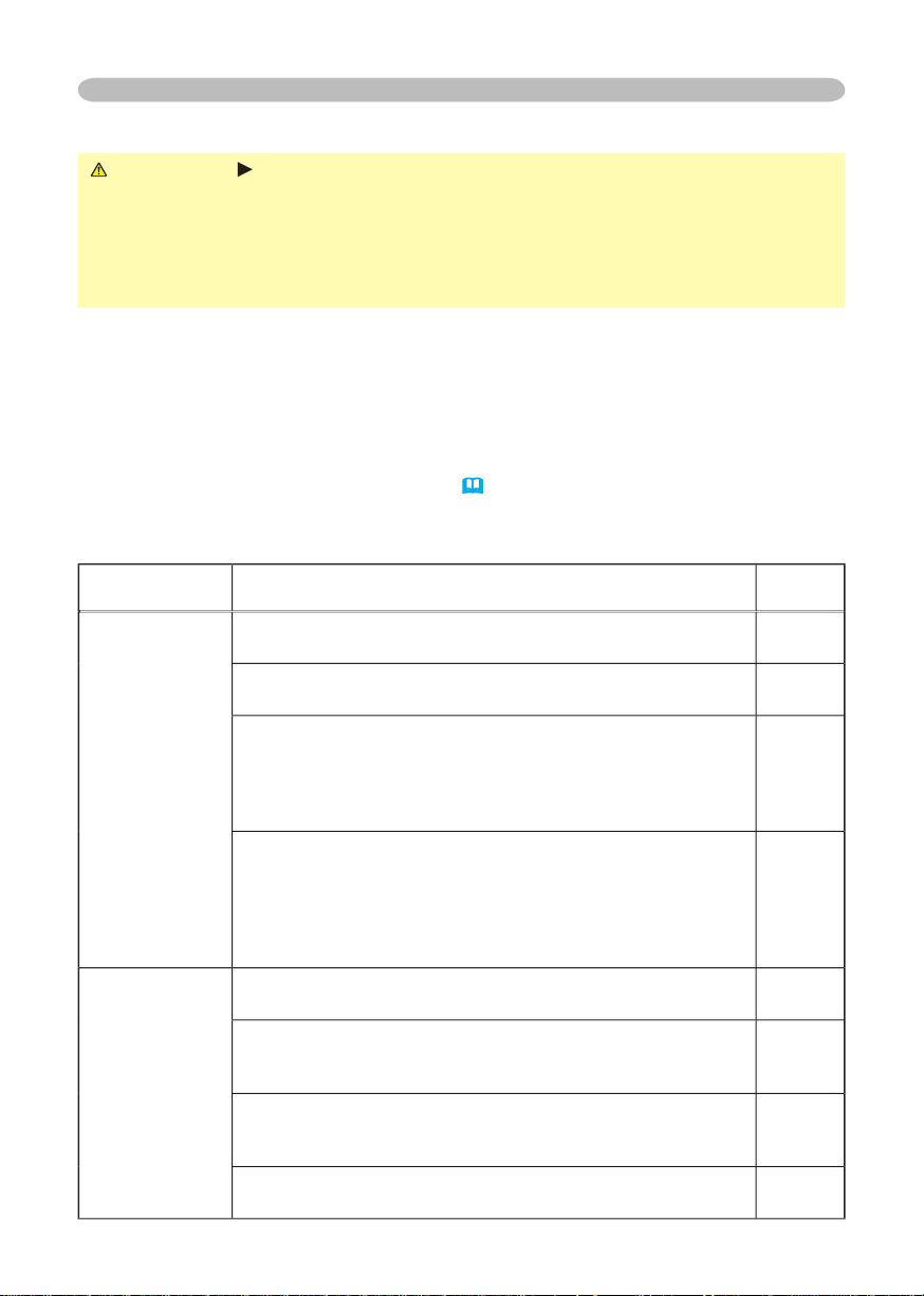
TEMP
Red
Red
Turned
Red
The cooling fan is not operating.
to
After the projector has
suffi ciently cooled down, please make confi rmation
that no foreign matter has become caught in the fan,
Red
Red
Turned
Red
There is a possibility that the interior portion
to
suffi ciently cooled down, please make confi rmation of
the following items, and then turn the power on again.
Green
Alternative
blinking in
Red
There is a possibility that the interior portion
within the usage temperature
Green
blinking in
Red
fi lter
After cleaning or changing
the air fi lter
to reset the fi lter timer. After the remedy, reset the
• When the interior portion has become overheated, for safety
Page 48
46
Troubleshooting
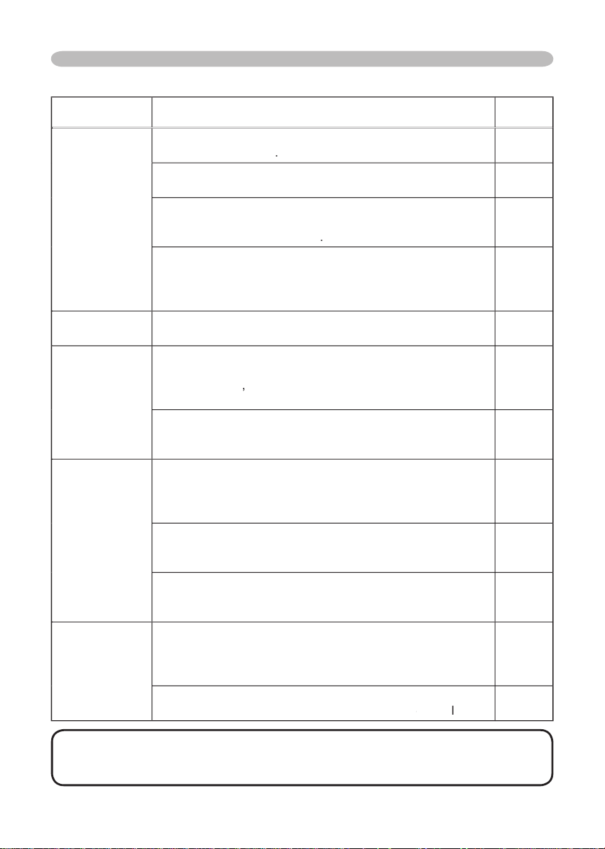
WARNING
the power outlet. After making sure that the smoke or odor has stopped, contact
your dealer or service company.
This operation sometimes resolves your problem.
The projector’s microprocessor may need to be reset. Please push the
(
to reset all settings to factory default.
Then, if the problem is not removed after the remedy, please contact your dealer
The electrical power cord is not plugged in.
The power switch is not set to the on position.
The main power source has been interrupted during
down at least 20 minutes. After the projector has suffi ciently
at least 45 minutes. After the projector has suffi ciently cooled
down, please make confi rmation of the attachment state of the
The signal cables are not correctly connected.
The MUTE function is working.
on the remote control.
The volume is adjusted to an extremely low level.
Adjust the volume to a higher level using the menu function
or the remote control.
The AUDIO setting is not correct.
Page 49
displayed.
The
is attached.
the lens
4, 16
The signal cables are not correctly connected.
The brightness is adjusted to an extremely low level.
Adjust BRIGHTNESS to a higher level using the menu
function
or the remote control
23, 25
The computer cannot detect the projector as a plug
Video screen
display freezes.
The FREEZE function is working.
21
faded- out
TEMP,
TINT and/or
settin
gs,
2
dark.
The brightness and/or contrast are adjusted to an
extremely low level.
Adjust BRIGHTNESS and/or CONTRAST settings to a
The WHISPER function is working.
2
The lamp is approaching the end of its product
Adjust the focus using t
PHASE
The lens is d
or ts
41
Troubleshooting
• Although bright spots or dark spots may appear on the screen, this
Page 50
48
Warranty And After-Service
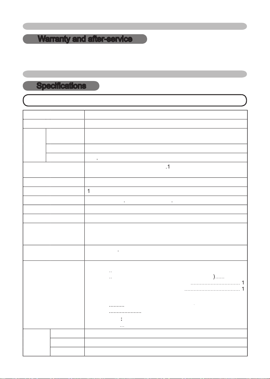
Warranty and after-service
through the suggested checks. If this does not resolve the problem, please contact your
Specifi cations
Specifi cations
• These specifi cations are subject to change without notice.
cm (0.7 type)
TFT active matrix
432
pixels (
horizont
ve
Zoom le
29.
Zoom le
230
W UHB
W x 1
AC100-120V
/
4
A, AC220-240V/
2
A
W
Temperature range
(W) x
(H) x
2
(D) mm
Weight (mass)
kg
Air fi lter
..
..
D-sub 15pin mini x1
Audio input:
AUDIO 1
AUDIO 2
Audio output
AUDIO OUT
...
Video input:
(Y,
/P
/P
......
................................
Video
kg, 8.2 lb.
456-8915
Page 51
49
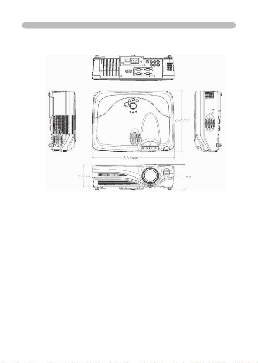
Specifi cations
Page 52
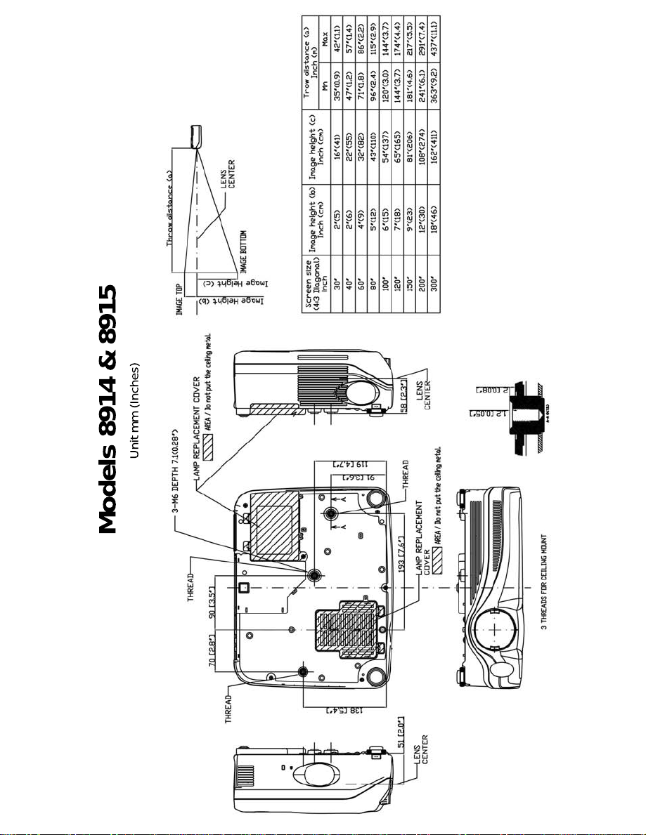
Models 8914 & 8915
Unit mm (Inches)
Page 53
8914
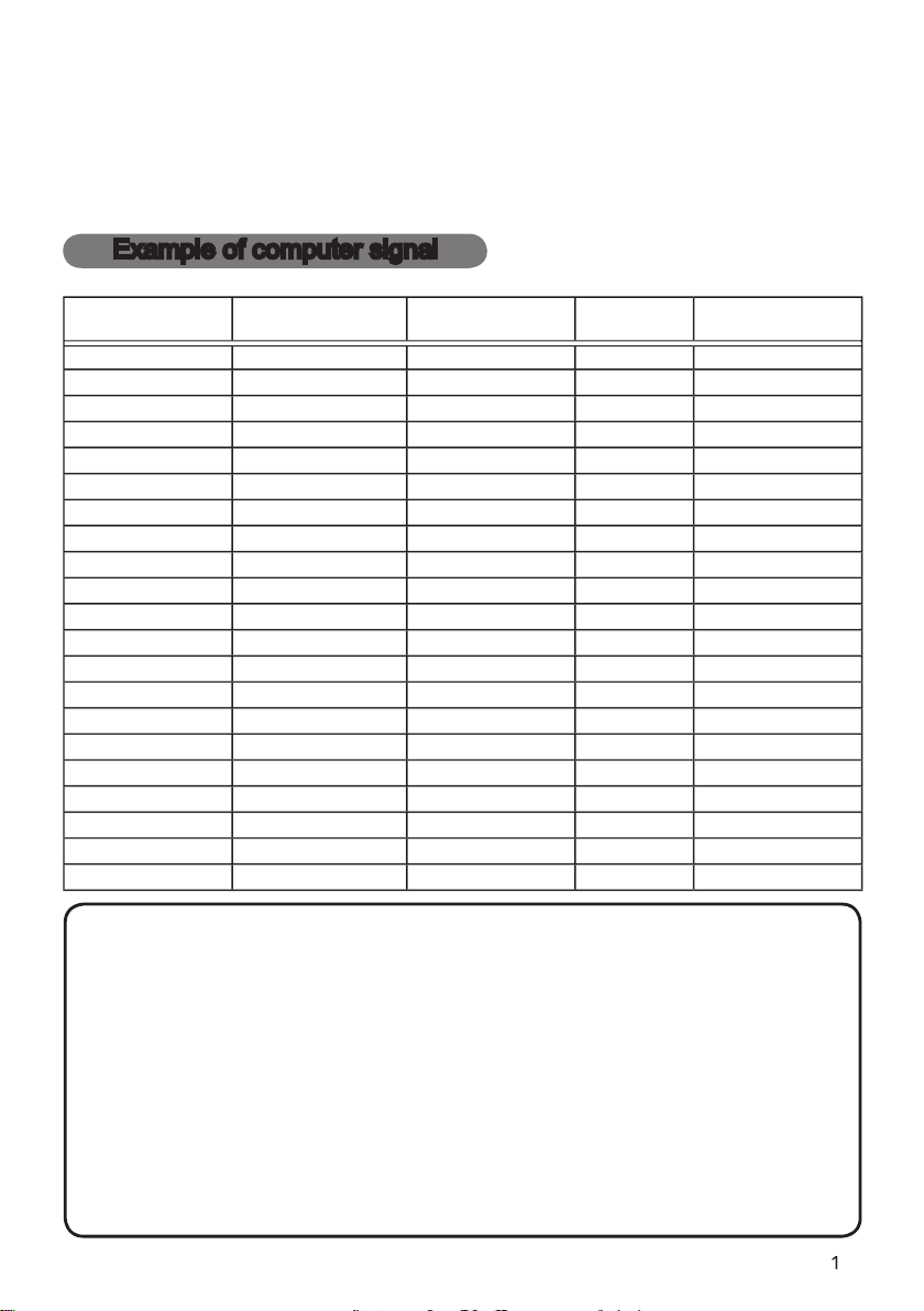
Example of computer signal
V. frequency (Hz)
VESA
VESA
VGA (60Hz)
VESA
VGA (72Hz)
VESA
VGA (75Hz)
43.3
VESA
VGA (85Hz)
VESA
VESA
48.1
VESA
46.9
VESA
VESA
49.7
48.4
VESA
XGA (60Hz)
VESA
XGA (70Hz)
VESA
XGA (75Hz)
VESA
XGA (85Hz)
VESA
VESA
VESA
VESA
VESA
VESA
• Be sure to check jack type, signal level, timing and resolution
these modes will not be possible with this projector.
Page 54
Example of computer signal
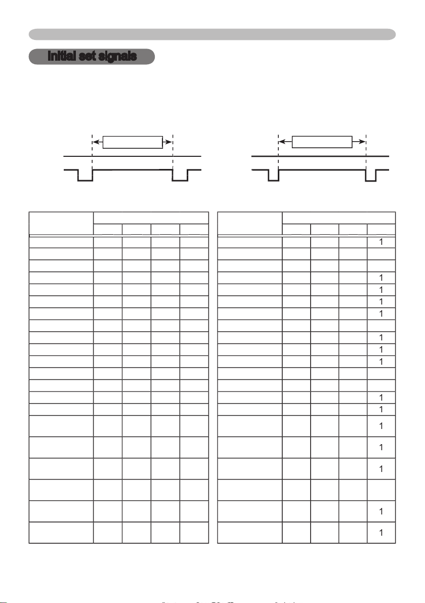
Initial set signals
The following signals are used for the initial settings. The signal timing of some
Sync (A) Sync (a)
Vertical signal timing (lines)
2.0
20.3
400
VGA (60Hz)
25.4
VGA (60Hz)
480
VGA (72Hz)
20.3
VGA (72Hz)
28
480
VGA (75Hz)
2.0
20.3
VGA (75Hz)
480
VGA (85Hz)
2.2
VGA (85Hz)
25
480
2.0
22.2222
2.2
20.0423
2.4
23
21
2.7
27
XGA (60Hz)
2.1
2.5
XGA (60Hz)
29
XGA (70Hz)
XGA (70Hz)
29
XGA (75Hz)
2.2
XGA (75Hz)
28
XGA (85Hz)
2.2
XGA (85Hz)
2.9
2.3
44
46
Page 55
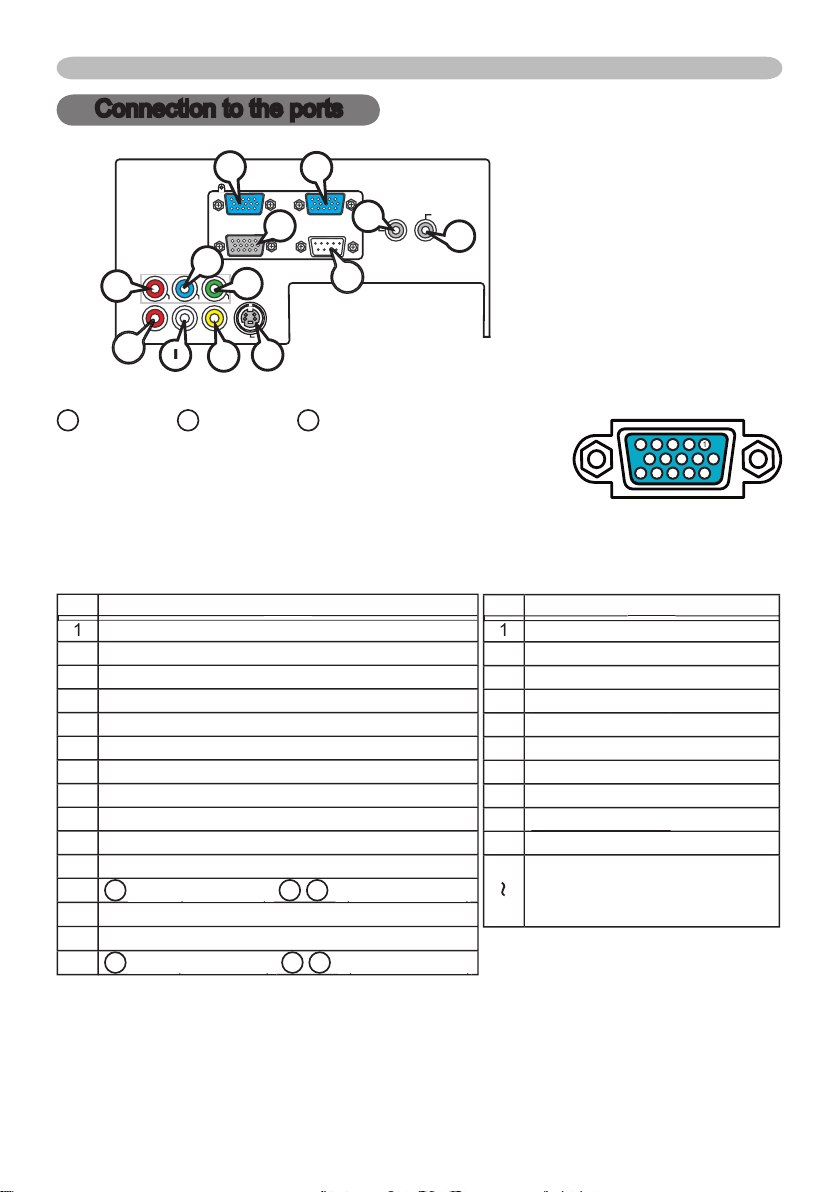
Connection to the ports
D-sub 15pin mini shrink jack
At RGB signal At component video signal
Video Red
2
Video Green
Video Blue
4
/
V. sync.
A
/
Y
VIDEO
RGB IN1 RGB IN2
RGB OUT CONTROL
AUDIO 1-IN
S-VIDEO
COMPONENT VIDEO
CB/P
B
CR/P
R
R-AUDIO 2-L
AUDIO-OUT
Connection to the ports
/P
Y
/P
/P
Ground
Y Ground
/P
Ground
* except for RGB OUT.
9
876
543
2
J
A
Page 56
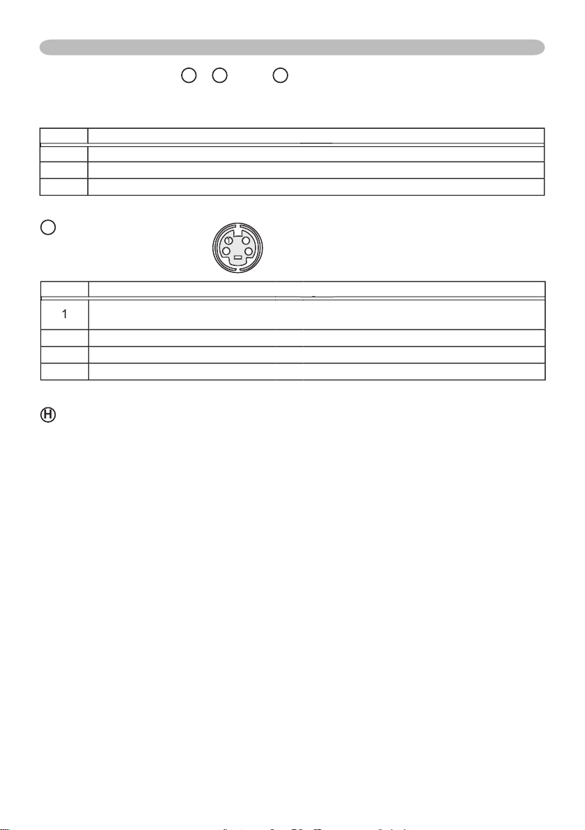
Connection to the ports
333
VIDEO
Y,
/P
/P
Y
/P
/P
/P
/P
Page 57
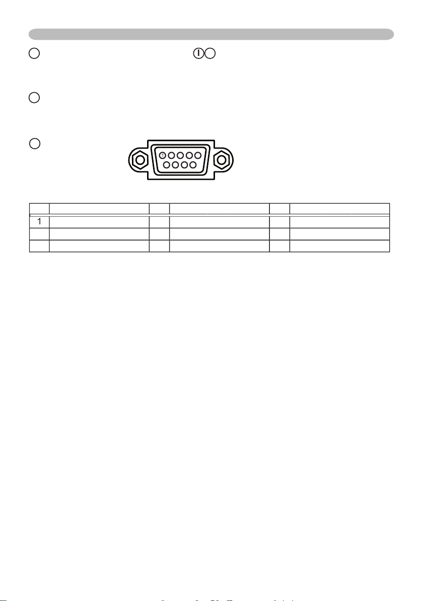
2
TD
Connection to the ports
AUDIO 1-IN (
J
AUDIO 2 L/R (RCA jack)
AUDIO OUT (
3
5
678
9
Page 58
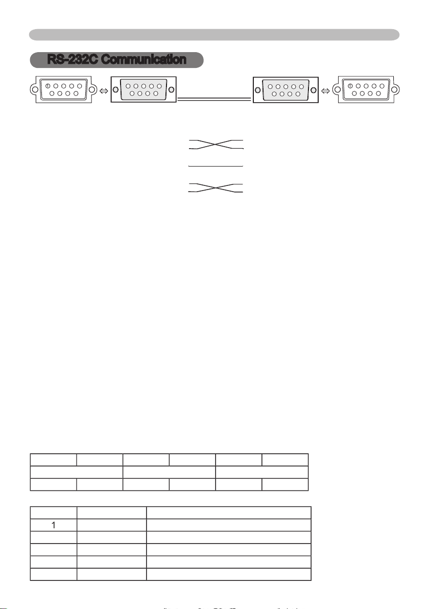
RS-232C Communication
RS-232C Communication
6
8
8
9
9
335
6
8
8
9
9
3
5
of the projector of the computer
- (1) (1) CD
RD (2) (2) RD
TD (3) (3) TD
- (4) (4) DTR
GND (5) (5) GND
- (6) (6) DSR
RTS (7) (7) RTS
CTS (8) (8) DTS
- (9) (9) RI
Turn off the projector and the computer.
the computer by a RS-232C cable (cross). Use the cable that fulfills the
Turn the computer on, and after the computer has started up turn the
2. Header
Action
Type
Action (byte_0 - 1)
Action
2
Page 59

RS-232C Communication (continued)
setting code (2 bytes)) from the computer to the projector.
When the projector cannot understand the received command
When the projector cannot understand the received command, the error code ‘15H’
When the projector cannot execute the received command.
When the projector cannot execute the received command, the error code ‘1cH’
• Operation cannot be guaranteed when the projector receives an undefi ned
Page 60
Operation Type
Command Data
CRC
Action
Type
Type
Type
Type
Setting Code
Setting Code
Setting Code
Setting Code
Set
Turn off0306 00
2A D3
01 00
00 60
00 00
Turn on0306 00
01 00
00 60
01 00
03
06 00
02 00
00 60
00 00
00 00 01 00 02 00
(Off) (On) (Cool down)
Set0306 00
01 00
00 20
00 00
03
06 00
3E D0
01 00
00 20
04 00
VIDEO0306 00
6E D3
01 00
00 20
01 00
S-VIDEO
03
06 00
9E D3
01 00
00 20
02 00
COMPONENT
03
06 00
01 00
00 20
05 00
03
06 00
CD D2
02 00
00 20
00 00
03
06 00
02 00
20 60
00 00
00 00 01 00 02 00 03 00
(Normal) (Cover error) (Fan error) (Lamp error)
04 00 05 00 06 00 07 00
(Temp error) (Air fl ow error) (Lamp time error) (Cool error)
08 00
09 00 10 00
(Filter error)
(Filter missing error) (Inner Sencer error)
03
06 00
89 D2
02 00
03 20
00 00
03
06 00
04 00
03 20
00 00
03
06 00
3E D3
05 00
03 20
00 00
03
06 00
58 D3
06 00
00 70
00 00
CONTRAST
03
06 00
02 00
04 20
00 00
03
06 00
9B D3
04 00
04 20
00 00
03
06 00
4A D2
05 00
04 20
00 00
CONTRAST Reset
03
06 00
A4 D2
06 00
01 70
00 00
Set0306 00
23 F6
01 00
00 00
CINEMA
03
06 00
01 00
01 00
03
06 00
01 00
04 00
03
06 00
02 00
00 00
00 00 01 00 04 00 10 00
(Normal) (Cinema) (Dynamic) (Custom)
Set
#1 DEFAULT
03
06 00
07 E9
01 00
A1 30
20 00
#1 CUSTOM
03
06 00
07 FD
01 00
A1 30
#2 DEFAULT
03
06 00
97 E8
01 00
A1 30
21 00
#2 CUSTOM
03
06 00
97 FC
01 00
A1 30
#3 DEFAULT
03
06 00
67 E8
01 00
A1 30
22 00
#3 CUSTOM
03
06 00
67 FC
01 00
A1 30
03
06 00
02 00
A1 30
00 00
RS-232C Communication (continued)
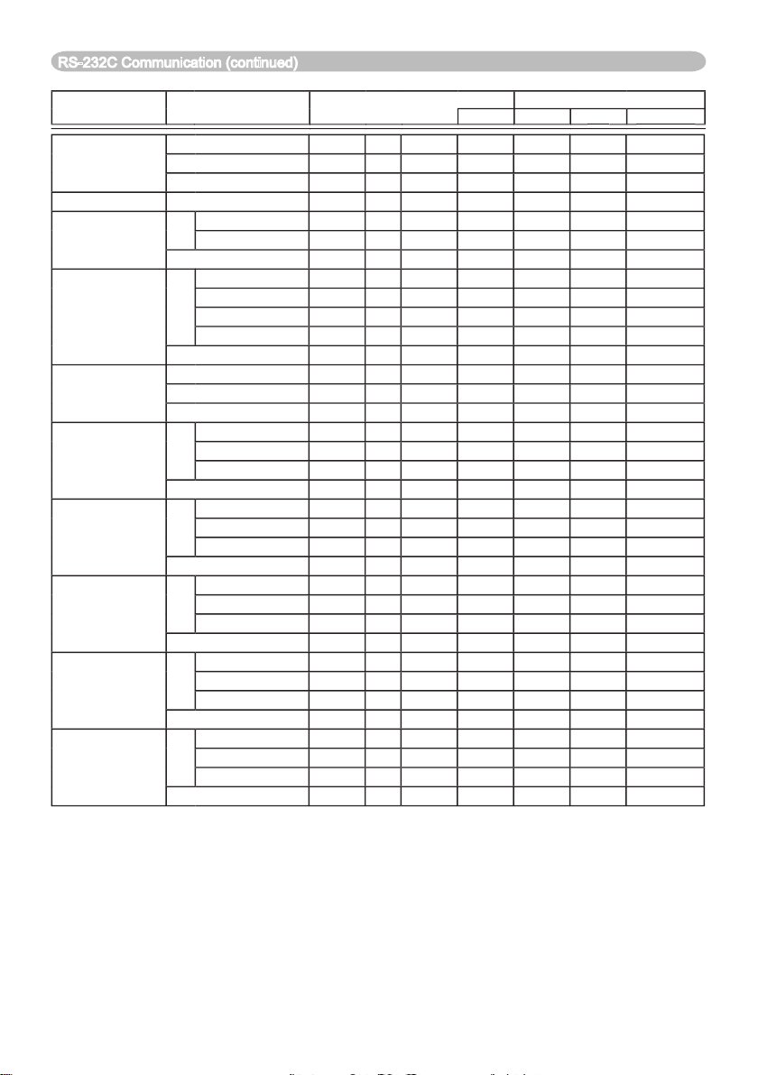
Page 61
Operation Type
Command Data
CRC
Action
Type
Type
Type
Setting Code
Setting Code
Setting Code
Set
Off0306 00
01 00
80 30
00 00
9 step gray scale
03
06 00
6B FB
01 00
80 30
01 00
03
06 00
9B FB
01 00
80 30
02 00
03
06 00
0B FA
01 00
80 30
03 00
03
06 00
C8 FA
02 00
80 30
00 00
03
06 00
08 FE
02 00
90 30
00 00
03
06 00
6E FE
04 00
90 30
00 00
03
06 00
05 00
90 30
00 00
03
06 00
02 00
91 30
00 00
03
06 00
92 FF
04 00
91 30
00 00
03
06 00
43 FE
05 00
91 30
00 00
03
06 00
02 00
92 30
00 00
03
06 00
04 00
92 30
00 00
03
06 00
07 FE
05 00
92 30
00 00
03
06 00
4C FE
02 00
93 30
00 00
03
06 00
2A FE
04 00
93 30
00 00
03
06 00
05 00
93 30
00 00
03
06 00
38 FF
02 00
94 30
00 00
03
06 00
5E FF
04 00
94 30
00 00
03
06 00
8F FE
05 00
94 30
00 00
03
06 00
C4 FE
02 00
95 30
00 00
03
06 00
04 00
95 30
00 00
03
06 00
73 FF
05 00
95 30
00 00
03
06 00
80 FE
02 00
96 30
00 00
03
06 00
04 00
96 30
00 00
03
06 00
37 FF
05 00
96 30
00 00
03
06 00
7C FF
02 00
97 30
00 00
03
06 00
04 00
97 30
00 00
03
06 00
CB FE
05 00
97 30
00 00
COLOR TEMP
Set0306 00
6B F4
01 00
01 00
03
06 00
9B F4
01 00
02 00
03
06 00
0B F5
01 00
03 00
CUSTOM
03
06 00
3B F8
01 00
03
06 00
C8 F5
02 00
00 00
COLOR TEMP GAIN R
03
06 00
34 F4
02 00
00 00
03
06 00
52 F4
04 00
00 00
03
06 00
83 F5
05 00
00 00
RS-232C Communication (continued)
Page 62
Operation Type
Command Data
CRC
Action
Type
Type
Setting Code
Setting Code
COLOR TEMP GAIN G
03
06 00
70 F4
02 00
00 00
03
06 00
04 00
00 00
03
06 00
C7 F5
05 00
00 00
COLOR TEMP GAIN B
03
06 00
8C F5
02 00
00 00
03
06 00
04 00
00 00
03
06 00
3B F4
05 00
00 00
COLOR TEMP
OFFSET R
03
06 00
04 F5
02 00
00 00
03
06 00
62 F5
04 00
00 00
03
06 00
05 00
00 00
COLOR TEMP
OFFSET G
03
06 00
40 F5
02 00
00 00
03
06 00
26 F5
04 00
00 00
03
06 00
05 00
00 00
COLOR TEMP
OFFSET B
03
06 00
02 00
00 00
03
06 00
04 00
00 00
03
06 00
0B F5
05 00
00 00
COLOR
03
06 00
02 00
02 22
00 00
03
06 00
04 00
02 22
00 00
03
06 00
02 73
05 00
02 22
00 00
COLOR Reset
03
06 00
80 D0
06 00
0A 70
00 00
TINT
03
06 00
49 73
02 00
03 22
00 00
03
06 00
2F 73
04 00
03 22
00 00
03
06 00
05 00
03 22
00 00
TINT Reset
03
06 00
7C D1
06 00
0B 70
00 00
SHARPNESS
03
06 00
02 00
01 22
00 00
03
06 00
97 72
04 00
01 22
00 00
03
06 00
46 73
05 00
01 22
00 00
SHARPNESS Reset
03
06 00
C4 D0
06 00
09 70
00 00
Set
TURN OFF
03
06 00
4A 72
01 00
07 22
00 00
TV
03
06 00
01 00
07 22
01 00
03
06 00
2A 73
01 00
07 22
02 00
03
06 00
79 72
02 00
07 22
00 00
Set0306 00
0E D7
01 00
00 00
03
06 00
9E D6
01 00
01 00
30306 00
6E D6
01 00
02 00
03
06 00
01 00
03 00
Set0306 00
01 00
00 00
2
03
06 00
62 D7
01 00
01 00
30306 00
92 D7
01 00
02 00
4
03
06 00
02 D6
01 00
03 00
RS-232C Communication (continued)
Page 63
Operation Type
Command Data
CRC
Action
Type
Type
Setting Code
Setting Code
ASPECT
Set
4:30306 00
9E D0
01 00
08 20
00 00
03
06 00
0E D1
01 00
08 20
01 00
SMALL0306 00
01 00
08 20
02 00
03
06 00
5E DD
01 00
08 20
03
06 00
AD D0
02 00
08 20
00 00
OVER SCAN
03
06 00
91 70
02 00
09 22
00 00
03
06 00
04 00
09 22
00 00
03
06 00
26 71
05 00
09 22
00 00
OVER SCAN Reset
03
06 00
06 00
27 70
00 00
V POSITION
03
06 00
0D 83
02 00
00 21
00 00
03
06 00
6B 83
04 00
00 21
00 00
03
06 00
05 00
00 21
00 00
V POSITION Reset
03
06 00
06 00
02 70
00 00
03
06 00
02 00
01 21
00 00
03
06 00
97 82
04 00
01 21
00 00
03
06 00
46 83
05 00
01 21
00 00
03
06 00
06 00
03 70
00 00
03
06 00
49 83
02 00
03 21
00 00
03
06 00
2F 83
04 00
03 21
00 00
03
06 00
05 00
03 21
00 00
03
06 00
02 00
02 21
00 00
03
06 00
04 00
02 21
00 00
03
06 00
02 83
05 00
02 21
00 00
03
06 00
68 D2
06 00
04 70
00 00
AUTO ADJUST
03
06 00
91 D0
06 00
0A 20
00 00
COLOR SPACE
Set
AUTO0306 00
0E 72
01 00
04 22
00 00
03
06 00
9E 73
01 00
04 22
01 00
SMPTE240
03
06 00
6E 73
01 00
04 22
02 00
03
06 00
01 00
04 22
03 00
03
06 00
CE 70
01 00
04 22
04 00
03
06 00
3D 72
02 00
04 22
00 00
COMPONENT
Set
COMPONENT
03
06 00
4A D7
01 00
00 00
SCART RGB
03
06 00
01 00
01 00
03
06 00
79 D7
02 00
00 00
VIDEO FORMAT
Set
AUTO0306 00
9E 75
01 00
00 22
0A 00
03
06 00
01 00
00 22
04 00
03
06 00
6E 70
01 00
00 22
05 00
SECAM
03
06 00
6E 75
01 00
00 22
09 00
03
06 00
5E 72
01 00
00 22
02 00
03
06 00
01 00
00 22
08 00
03
06 00
0E 71
01 00
00 22
07 00
03
06 00
0D 73
02 00
00 22
00 00
RS-232C Communication (continued)
Page 64
Operation Type
Command Data
CRC
Action
Type
Type
Setting Code
Setting Code
03
06 00
02 00
07 20
00 00
03
06 00
04 00
07 20
00 00
03
06 00
0E D2
05 00
07 20
00 00
03
06 00
08 D0
06 00
0C 70
00 00
WHISPER
Set0306 00
3B 23
01 00
00 33
00 00
WHISPER
03
06 00
AB 22
01 00
00 33
01 00
03
06 00
08 23
02 00
00 33
00 00
Set0306 00
C7 D2
01 00
01 30
00 00
03
06 00
57 D3
01 00
01 30
01 00
03
06 00
A7 D3
01 00
01 30
02 00
03
06 00
37 D2
01 00
01 30
03 00
03
06 00
02 00
01 30
00 00
VOLUME
03
06 00
31 D3
02 00
01 20
00 00
03
06 00
57 D3
04 00
01 20
00 00
03
06 00
86 D2
05 00
01 20
00 00
AUDIO - RGB1
Set
TURN OFF
03
06 00
01 00
30 20
00 00
Audio10306 00
6E DC
01 00
30 20
01 00
Audio20306 00
9E DC
01 00
30 20
02 00
03
06 00
CD DD
02 00
30 20
00 00
AUDIO - RGB2
Set
TURN OFF
03
06 00
CE DC
01 00
34 20
00 00
Audio10306 00
5E DD
01 00
34 20
01 00
Audio20306 00
01 00
30 20
02 00
03
06 00
02 00
34 20
00 00
AUDIO - Video
Set
TURN OFF
03
06 00
02 DC
01 00
31 20
00 00
Audio10306 00
92 DD
01 00
31 20
01 00
Audio20306 00
62 DD
01 00
30 20
02 00
03
06 00
31 DC
02 00
31 20
00 00
AUDIO - S-Video
Set
TURN OFF
03
06 00
46 DC
01 00
32 20
00 00
Audio10306 00
01 00
32 20
01 00
Audio20306 00
26 DD
01 00
30 20
02 00
03
06 00
75 DC
02 00
32 20
00 00
AUDIO - Component
Set
TURN OFF
03
06 00
32 DD
01 00
35 20
00 00
Audio10306 00
A2 DC
01 00
35 20
01 00
Audio20306 00
52 DC
01 00
30 20
02 00
03
06 00
01 DD
02 00
35 20
00 00
RS-232C Communication (continued)
Page 65
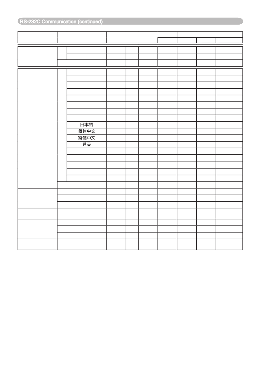
Operation Type
Command Data
CRC
Action
Type
Type
Type
Setting Code
Setting Code
Setting Code
Set
TURN OFF
03
06 00
46 D3
01 00
02 20
00 00
TURN ON
03
06 00
01 00
02 20
01 00
03
06 00
75 D3
02 00
02 20
00 00
Set0306 00
01 00
05 30
00 00
03
06 00
67 D2
01 00
05 30
01 00
03
06 00
97 D2
01 00
05 30
02 00
03
06 00
07 D3
01 00
05 30
03 00
03
06 00
37 D1
01 00
05 30
04 00
03
06 00
A7 D0
01 00
05 30
05 00
03
06 00
57 D0
01 00
05 30
06 00
03
06 00
C7 D1
01 00
05 30
07 00
03
06 00
37 D4
01 00
05 30
08 00
03
06 00
A7 D5
01 00
05 30
09 00
03
06 00
37 DE
01 00
05 30
03
06 00
57 D5
01 00
05 30
0A 00
SVENSKA
03
06 00
C7 D4
01 00
05 30
0B 00
03
06 00
01 00
05 30
0C 00
SUOMI0306 00
67 D7
01 00
05 30
0D 00
03
06 00
97 D7
01 00
05 30
0E 00
TÜRKÇE
03
06 00
07 D6
01 00
05 30
0F 00
03
06 00
C4 D3
02 00
05 30
00 00
03
06 00
04 D7
02 00
00 00
03
06 00
62 D7
04 00
00 00
03
06 00
05 00
00 00
03
06 00
06 00
43 70
00 00
03
06 00
40 D7
02 00
00 00
03
06 00
26 D7
04 00
00 00
03
06 00
05 00
00 00
03
06 00
A8 C7
06 00
44 70
00 00
RS-232C Communication (continued)
Page 66
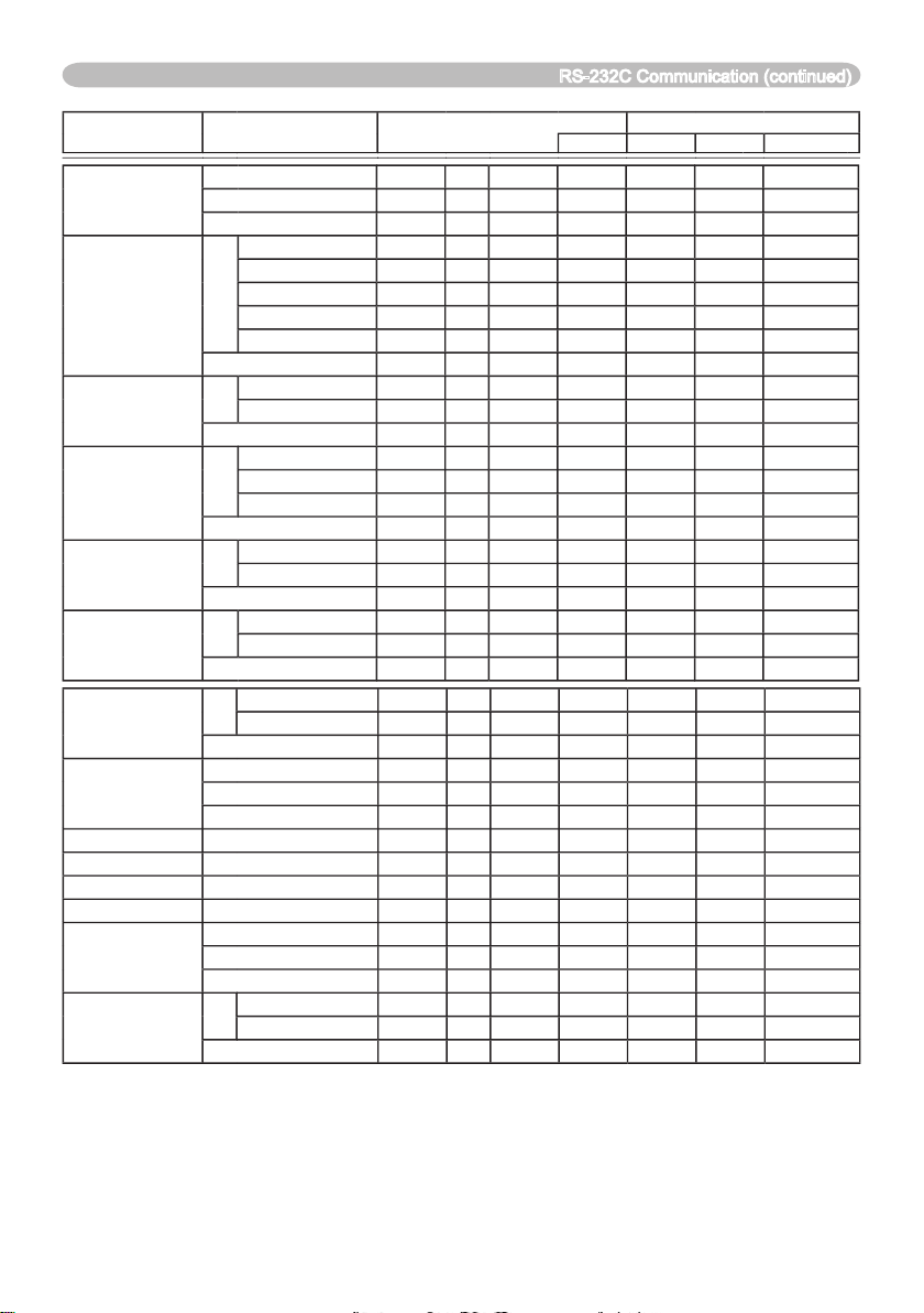
Operation Type
Command Data
CRC
Action
Type
Type
Type
Setting Code
Setting Code
Setting Code
OSD BRIGHT.
03
06 00
A8 D5
02 00
00 00
03
06 00
CE D5
04 00
00 00
03
06 00
05 00
00 00
Set
03
06 00
01 00
00 30
20 00
ORIGINAL
03
06 00
01 00
00 30
40 00
03
06 00
CB D3
01 00
00 30
03 00
03
06 00
6B D0
01 00
00 30
05 00
03
06 00
9B D0
01 00
00 30
06 00
03
06 00
08 D3
02 00
00 30
00 00
Set
TURN OFF
03
06 00
01 00
20 30
00 00
TURN ON
03
06 00
6B D9
01 00
20 30
01 00
03
06 00
C8 D8
02 00
20 30
00 00
START UP
Set0306 00
CB CB
01 00
04 30
20 00
ORIGINAL
03
06 00
0B D2
01 00
04 30
00 00
TURN OFF
03
06 00
9B D3
01 00
04 30
01 00
03
06 00
38 D2
02 00
04 30
00 00
Set
TURN OFF
03
06 00
3B EF
01 00
C0 30
00 00
TURN ON
03
06 00
01 00
C0 30
01 00
03
06 00
08 EF
02 00
C0 30
00 00
Set
TURN OFF
03
06 00
8F D6
01 00
00 00
TURN ON
03
06 00
01 00
01 00
03
06 00
02 00
00 00
AUTO SEARCH
Set
TURN OFF
03
06 00
01 00
00 00
TURN ON
03
06 00
26 D7
01 00
01 00
03
06 00
85 D6
02 00
00 00
AUTO POWER OFF
03
06 00
08 86
02 00
00 00
03
06 00
6E 86
04 00
00 00
03
06 00
05 00
00 00
03
06 00
C2 FF
02 00
90 10
00 00
03
06 00
58 DC
06 00
30 70
00 00
03
06 00
C2 F0
02 00
A0 10
00 00
03
06 00
98 C6
06 00
40 70
00 00
03
06 00
7C D2
02 00
07 30
00 00
03
06 00
04 00
07 30
00 00
03
06 00
CB D3
05 00
07 30
00 00
Set0306 00
83 D2
01 00
02 30
00 00
03
06 00
01 00
02 30
01 00
03
06 00
02 00
02 30
00 00
RS-232C Communication (continued)
Page 67

Page 68

2900 Dukane Drive
St. Charles, Illinois 60174
www.dukcorp.com/av
Audio Visual Products
Toll-free: 800-676-2487
Fax: 630-584-5156
e-mail: [email protected]
#401-8914-00
 Loading...