

Dukane 8760 User Manual
Portable Projector
8760/8761
User's Manual
About this user's manual
The fastest way to get started is to take your time and do everything right the first time. Take a few minutes now to review the
user's manual. This may save you time later on. At the beginning of each section of the manual you'll find an overview. If the
section doesn't apply, you can skip it.

INTRODUCTION
Introduction to the Projector
This section introduces you to your new 8760/8761 Projector and
describes the features and controls.
Congratulations on Your Purchase of The 8760/
8761 Projector
The 8760/8761 is one of the very best projectors available today. The
8760/8761 enables you to project precise images up to 500 inches
across (measured diagonally) from your PC or Macintosh computer (desktop or notebook), VCR, DVD player, document camera, a laser disc player
or Viewer.
You can use the projector on a tabletop or cart, you can use the projector
to project images from behind the screen, and the projector can be permanently mounted on a ceiling*1. The remote control can be used wirelessly.
*1Do not attempt to mount the projector on a ceiling yourself.
The projector must be installed by qualified technicians in order to ensure proper operation and reduce the risk of bodily injury.
In addition, the ceiling must be strong enough to support the projector
and the installation must be in accordance with any local building codes.
Please consult your dealer for more information.
Features you'll enjoy:
• The newly developed 3D Reform function allows you to correct trapezoidal distortion for both horizontally and vertically so that the image is square even when projector is positioned off center of the
rooms screen.
• The 8760/8761 projector provides wired and wireless networking
When using as a wireless LAN projector, no physical signal cable
connection to a PC is required.*
*2 A wireless LAN card is required.
E-2
2

INTRODUCTION ⬎ Introduction to the Projector
• Safety protect by Password and Security functions
Password and Security features prevent the projector from being used
by unauthorized individuals.
Password prevents unauthorized individuals from changing projector
settings or adjustments. Security offers complete protection by using
your PC card as a protect key so that the projector will not project a
signal without insertion of the registered PC card and unauthorized
use can be discouraged.
• The built-in Viewer allows you to start your presentation even when a
PC is not available at the site.
•A high-bright 220 watt DC lamp.
• The Standby mode reduces standby power consumption significantly.
• The supplied wireless remote control that operates the projector from
the front side or rear.
• The image can be projected between 30 and 500 inches (measured
diagonally).
• The "Capture" enables you to capture the current projected image.
• An image can be projected from in front or behind a screen, and the
projector can even be installed on the ceiling.
• Dukane’s exclusive intelligent pixel blending technology-
an extremely accurate image compression technology - offers
a crisp image with UXGA (1600⳯1200) resolution
• Supports most IBM VGA, SVGA, XGA , SXGA/UXGA,
Macintosh, component signal (YCbCr/ YPbPr) or any
other RGB signals within a horizontal frequency range of 24 to 100
kHz and a vertical frequency range of 50 to 120 Hz. This includes
NTSC, PAL, PAL-N, PAL-M, PAL60, SECAM and NTSC4.43 standard video signals.
E-3

INTRODUCTION ⬎ Introduction to the Projector
NOTE: Composite video standards are as follows:
NTSC: U.S. TV standard for video in U.S. and Canada.
PAL: TV standard used in Western Europe.
PAL-N: TV standard used in Argentine, Paraguay and Uruguay.
PAL-M: TV standard used in Brazil.
PAL60: TV standard used for NTSC playback on PAL TVs.
SECAM: TV standard used in France and Eastern Europe.
NTSC4.43: TV standard used in Middle East countries.
E-4

INTRODUCTION ⬎ Introduction to the Projector
• The supplied remote control can be used without a cable, and you
can even use the remote control to operate your PC's mouse wirelessly
from across the room with the built-in remote mouse function.
•You can control the projector with a PC using the PC Control port.
• USB port allows USB mouse operation*4.
*4The USB ports meet the USB1.1 specification.
• The contemporary cabinet design is light, compact, easy to carry,
and complements any office, boardroom or auditorium.
• Nine pointers are available for your presentation.
E-5
INTRODUCTION ⬎ Part Names of the Projector
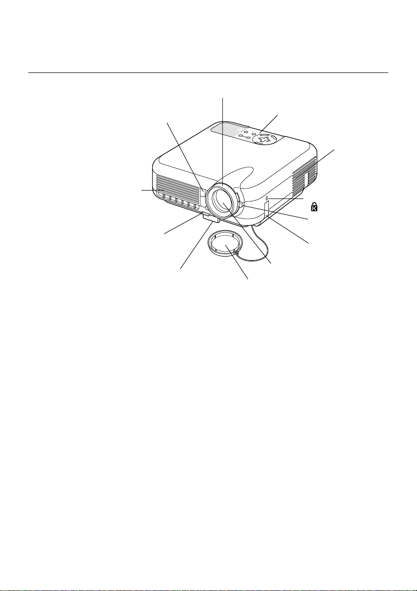
Part Names of the Projector
Focus Ring
(See page E-43)
Remote Sensor
(See page E-20)
Controls
(See page E-8)
POWER
Y
B
STATUS
D
N
A
T
S
N
LAMP
O
T
N
E
M
N
G
I
L
A
T
S
U
J
D
A
O
T
C
N
E
A
U
L
C
A
E
D
C
R
R
A
U
-C
O
C
S
P
R
E
T
N
E
T
C
E
L
E
S
U
N
E
M
Ventilation (inlet)
Ventilation (outlet)
Heated air is exhausted
from here
Built-in Security Slot
( )*
Zoom Lever
Adjustable Tilt Foot Lever
(See page E-43)
(See page E-42)
Adjustable Tilt Foot
(See page E-42)
Lens
Lens Cap
Carrying Handle
* This security slot supports the MicroSaver® Security System.
MicroSaver
®
is a registered trademark of Kensington Microware Inc.
The logo is trademarked and owned by Kensington Microware Inc.
E-6
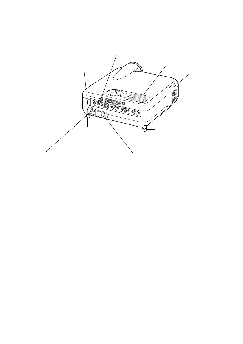
INTRODUCTION ⬎ Part Names of the Projector
PC Card Eject Button
PC Card Slot
Remote Sensor
(See page E-20)
Rear Foot
AC Input
Connect the supplied power cable's three-pin
plug here, and plug the other end into an active
wall outlet.
(See page E-35)
Monaural Speaker (2W)
Lamp cover
(See page E-121)
Ventilation
(outlet)
Lamp cover screw
Rear Foot
Rotate to make the projector level.
(See page E-43)
Main Power Switch
When you plug the supplied power cable into an active wall outlet and turn on the Main Power switch,
the POWER indicator turns orange and the projector
is in standby mode.
(See page E-36)
E-7
INTRODUCTION ⬎ Part Names of the Projector
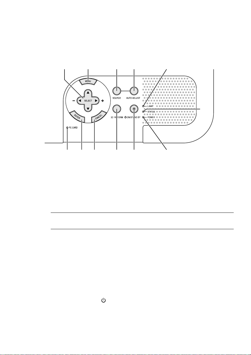
Top Features
910 45 11
678 121 3
1.POWER Button (ON / STAND BY)
Use this button to turn the power on and off when the main power is
supplied and the projector is in standby mode.
2
NOTE: To turn on or off the projector, press and hold this button for a mini-
mum of two seconds.
2. STATUS Indicator
If this light blinks red rapidly, it indicates that an error has occurred, the
lamp cover is not attached properly or the projector has overheated. If
this light remains orange, it indicates that you have pressed a cabinet
key while the Control Panel Key Lock is enabled. See the Status Indicator section on page E-126 for more details.
3. POWER Indicator ( )
When this indicator is green, the projector is on; when this indicator is
orange, it is in standby or idle mode. See the Power Indicator section
on page E-126 for more details.
E-8

INTRODUCTION ⬎ Part Names of the Projector ⬎ Top Features
4. SOURCE Button
Use this button to select a video source such as a PC, VCR, DVD
player, Viewer (PC card), or LAN.
Press and release this button quickly to display the Source List.
Each time this button is pressed for a minimum of ONE second, the
input source will change as follows:
RGB1 → RGB2 → Video → S-Video → Viewer → RGB1 → ...
If no input signal is present, the input will be skipped.
5. AUTO ADJUST Button
Use this button to adjust Position-H/V and Pixel Clock/Phase for an
optimal picture. Some signals may not be displayed correctly or take
time to switch between sources.
6. PC CARD Access Indicator
Lights while accessing a PC card.
7. ENTER Button
Executes your menu selection and activates items selected from the
menu.
8. CANCEL Button
Press this button to exit "Menus". Press this button to return the adjustments to the last condition while you are in the adjustment or setting
menu.
9. SELECT (+) (–) / Volume Buttons
: Use these buttons to select the menu of the item you wish to
adjust. When no menus appear, these buttons work as a volume
control.
E-9

INTRODUCTION ⬎ Part Names of the Projector ⬎ Top Features
: Use these buttons to change the level of a selected menu item.
A press of the button executes the selection. When the menus
or the Viewer tool bar is not displayed, these buttons can be
used to select a slide, or to move the cursor in Folder List or
Slide List.
When the pointer is displayed, these buttons move the pointer.
10. MENU Button
Displays the menu.
11. LAMP Indicator
If this light blinks red rapidly, it's warning you that the projection lamp
has exceeded 2000 hours (up to 3000 hours in Eco mode) of service.
After this light appears, replace the lamp as soon as possible. (See
page E-121). If this is lit green continually, it indicates that the lamp
mode is set to Eco. See the Lamp Indicator section on page E-127 for
more details.
12. 3D REFORM Button
Press this button to enter 3D Reform mode to correct the keystone
(trapezoidal) distortion, and make the image square.
E-10
INTRODUCTION ⬎ Part Names of the Projector ⬎ Terminal Panel Features
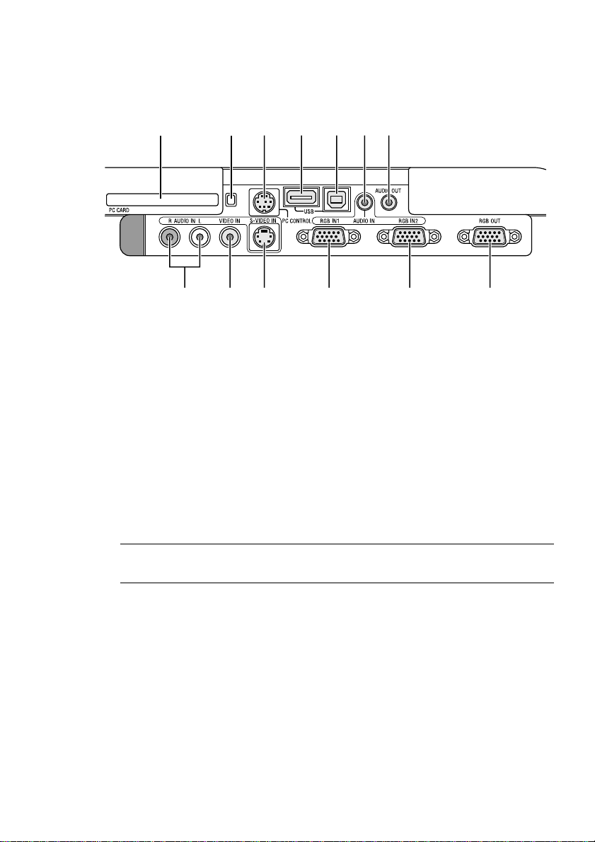
Terminal Panel Features
10 11 3 5
91213
1. RGB IN 1 / Component Input Connector (Mini D-Sub 15 Pin)
Connect your computer or other analog RGB equipment such as IBM
compatible or Macintosh computers. Use the supplied RGB cable to
connect to your computer. This also serves as a component input connector that allows you to connect a component video output of component equipment such as a DVD player. This connector also supports
SCART output signal. See page E-28 for more details.
421678
2. RGB IN 2 / Component Input Connector (Mini D-Sub 15 Pin)
This connector has the same function as the RGB IN 1 connector.
NOTE: The RGB IN 2 does not support SCART output signal and Plug &
Play.
3. RGB AUDIO IN Mini Jack (Stereo Mini)
This is where you connect audio output from your computer or DVD
player. A commercially available audio cable is required.
4. RGB OUT Connector (Mini D-Sub 15 Pin)
You can use this connector to loop your computer image to an external
monitor from the RGB 1 or 2 input source.
The RGB analog signal set on RGBOUT Terminal is output during idle
mode. See pages E-31 and 100.
E-11

INTRODUCTION ⬎ Part Names of the Projector ⬎ Terminal Panel Features
5. AUDIO OUT Mini Jack (Stereo Mini)
Connect an additional audio equipment here to listen to audio coming
from your computer, Video or S- Video input.
Note that there is no audio output from this jack during Standby and
Idle.
6 S-VIDEO IN Connector (Mini DIN 4 Pin)
Here is where you connect the S-Video input from an external source
like a VCR.
NOTE: S-Video provides more vivid color and higher resolution than the tra-
ditional composite video format.
7. VIDEO IN Connector (RCA)
Connect a VCR, DVD player, laser disc player, or document camera
here to project video.
8. VIDEO AUDIO IN Jacks (RCA)
L : This is your left channel audio input for stereo sound coming from
the VIDEO source.
R : This is your right channel audio input for stereo sound from the
VIDEO source.
9. PC CONTROL Port (Mini DIN 8 Pin)
Use this port to connect your PC to control your projector via a serial
cable. This enables you to use your PC and serial communication protocol to control the projector. The optional serial cable (CA03D) is
required to use this port. You can also control the projector by using
Dynamic Image Utility 2.0 included on the supplied CD-ROM.
To do so you must first have Dynamic Image Utility 2.0 installed on your
PC. If you are writing your own program, typical PC control codes are
on page E-136. A cap is put on the port at the factory. Remove the cap
when using the port.
E-12

INTRODUCTION ⬎ Part Names of the Projector ⬎ Terminal Panel Features
10. USB Port (Type A)
Connect a commercially available mouse that supports USB. You can
operate the menu or Viewer with the USB mouse via this port.
Note that this port should not be connected to a computer and that
there may be some brands of USB mouse that the projector does not
support.
11. USB Port (Type B)
Connect this port to the USB port (type A) of your PC using the supplied USB cable. You can operate your computer's mouse functions
from the remote control.
12. PC CARD Eject Button
Press to eject a PC card partially.
13. PC CARD Slot
Insert a PC card, commercially available LAN card or optional
wireless LAN card here.
E-13
INTRODUCTION ⬎ Part Names of the Remote Control
A
NIF
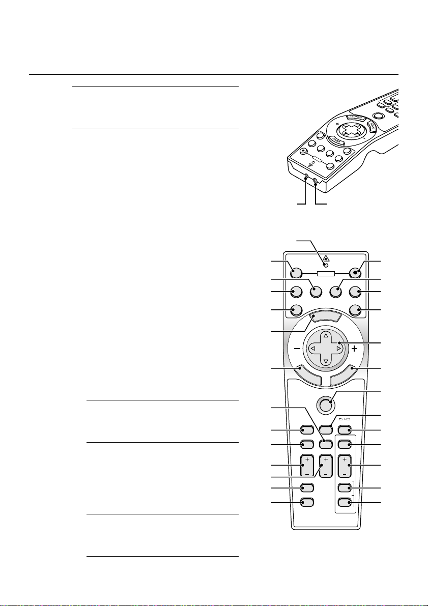
Part Names of the Remote Control
NOTE: If you are using a Macintosh com-
puter, you can click either the right-click
or left-click button to activate the mouse.
1. Infrared Transmitter
Direct the remote control toward
the remote sensor on the projector
cabinet.
2. LASER Pointer
Beams a laser light when the LASER button is pressed.
3. LED
Flashes when any button is
pressed.
4. POWER ON Button
If the main power is applied, you
can use this button to turn your projector on.
NOTE: To turn on the projector, press
and hold the POWER ON button for a
minimum of two seconds.
5. POWER OFF Button
You can use this button to turn your
projector off.
NOTE: To turn off the projector, press
and hold the POWER OFF button for
a minimum of two seconds.
12
21
17
20
22
23
24
25
5
7
LASER
RGB2
RGB1
ON
POWER
2 1
3
OFF
POWER
VIDEO
S-VIDEO RGB1 RGB2
AUTO ADJ.
E
M
SELECT
E
N
T
E
R
PJ
ASPECT
FREEZE
HELP
POINTER
VOLUME MAGNIFY
PICTURE
PIC-MUTE
OFF
N
U
S-VIDEO
VIDEO
A
C
3D REFORM
VIEWER
SLIDE
FOLDER
SLIDE
SLIDE
R
E
W
Y
IE
V
3D REFORM
INTER
PO
E
Z
E
E
R
F
SPECT
PJ
SELECT
AUTO ADJ.
4
ON
8
LASER
96
1110
13
L
E
C
N
1514
16
18
19
26
27
28
LIST
29
E-14

INTRODUCTION ⬎ Part Names of the Remote Control
6. VIDEO Button
Press this button to select an NTSC, PAL, PAL-N, PAL-M, PAL60,
SECAM or NTSC4.43 compatible video source from a VCR, DVD player,
or laser disc player.
7. S-VIDEO Button
Press this button to select an S-Video source from a VCR.
8. RGB 1 Button
Press this button to select a video source from computer or component
equipment connected to your RGB IN 1 port.
9. RGB 2 Button
Press this button to select a video source from computer or component
equipment connected to your RGB IN 2 port.
10. AUTO ADJ Button
Use this button to adjust an RGB source for an optimal picture. Some
signals may not be displayed correctly or take time to be displayed.
See page E-47.
11. LASER Button
Press and hold this button to activate the laser pointer. When lit, you
can use the laser to draw your audience's attention to a red dot that
you can place on any object.
12. MENU Button
Displays the menu for various settings and adjustments.
E-15

INTRODUCTION ⬎ Part Names of the Remote Control
13. SELECT (Mouse) Button
When you are in the Computer mode, these buttons work as a computer mouse. When you are in the Projector mode, which is indicated
by lighting the PJ button. See page E-52.
: Use these buttons to select the menu of the item you wish to
adjust.
: Use these buttons to change the level of a selected menu item.
A press of the button executes the selection.
When the pointer is displayed, these buttons move the pointer.
When the pointer is not displayed, these buttons are for adjust-
ing the image.
14. ENTER (Left Click) Button
When you are in the Computer mode, this button works as the mouse
left button. When this button is pressed and held for a minimum of 2
seconds, the drag mode is set. When you are in the Projector mode,
which is indicated by lighting the PJ button:
Use this button to enter your menu selection. It works the same way as
the ENTER button on the cabinet. See page E-9.
15. CANCEL (Right Click) Button
When you are in the Computer mode, this button works as the mouse
right button. When you are in the Projector mode, which is indicated by
lighting the PJ button: Press this button to exit the Menus. It works the
same way as the CANCEL button on the cabinet.
16. PJ Button
Press this button to switch the SELECT, CANCEL, and ENTER buttons between the Projector mode (lit red) and the Computer mode.
Press this button or any one of the POWER ON/OFF, MENU, ASPECT,
3D REFORM, HELP, POINTER, MAGNIFY, PICTURE, VIEWER,
FOLDER LIST or SLIDE LIST buttons to switch to the Projector mode
and the PJ button lights red. To switch back to the Computer mode,
press the PJ button again. See page E-52.
E-16

INTRODUCTION ⬎ Part Names of the Remote Control
17. ASPECT Button
Press this button to display the Aspect Ratio select screen. See page
E-86.
18. FREEZE Button
This button will freeze a picture. Press again to resume motion.
19. 3D REFORM Button
Press this button to enter 3D Reform to correct the keystone (trapezoidal) distortion, and make the image square. See page E-44.
20. HELP Button
Provides the online help or the set information.
21. POINTER Button
Press this button to display one of the eight pointers; press again to
hide the pointer. You can move your pointer icon to the area you want
on the screen using the Select button. See page E-54.
22. VOLUME (+) (–) Button
Press (+) to increase the volume and (–) to decrease it.
23. MAGNIFY (+) (–) Button
Use this button to adjust the image size up to 400%. When the pointer
is displayed, the image is magnified about the center of the pointer.
When the pointer is not displayed, the image is magnified about the
center of the screen. When the image is magnified, the pointer is
changed to the magnifying icon. See page E-55.
24. PICTURE Button
Press this button to display the Picture adjustement screen such as
Brightness, Contrast, Color, Hue, and Sharpness. See page E-85.
E-17

INTRODUCTION ⬎ Part Names of the Remote Control
25. PICTURE MUTE Button
This button turns off the image and sound for a short period of time.
Press again to restore the image and sound.
NOTE: When the menu is displayed, a press of this button mutes an image and
sound without turning off the menu.
26. VIEWER Button
Press this button to select the Viewer source.
27. SLIDE (+) (–) Button
Press (+) to select the next folder or slide and (–) to select the previous
folder or slide. See page E-67.
28. FOLDER LIST Button
Press this button to select Viewer source to display a list of folders
included in a PC card. See page E-67.
29. SLIDE LIST Button
Press this button to select Viewer source to display a list of slides included in a PC card. See page E-67.
NOTE: The default is the Computer mode, which allows you to use the SE-
LECT, CANCEL, and ENTER buttons as your computer mouse. When the
POWER ON/OFF, MENU, ASPECT, 3D REFORM, HELP, POINTER, MAG-
NIFY, PICTURE, VIEWER, FOLDER LIST, or SLIDE LIST button is pressed,
the PJ button lights red to indicate that you are in the Projector mode. If no
buttons are pressed within 60 seconds, the light goes out and the Projector
mode is canceled.
E-18
INTRODUCTION ⬎ Part Names of the Remote Control
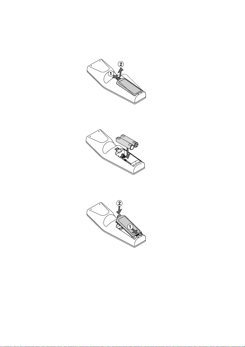
Battery Installation
1. Press the catch and remove the battery cover.
2. Remove both old batteries and install new ones (AA). Ensure that you
have the batteries' polarity (+/-) aligned correctly.
3. Slip the cover back over the batteries until it snaps into place. Do not mix
different types of batteries or new and old batteries.
Note on Remote Control Operation:
If you press and hold the SELECT button while installing new
batteries, the remote control may fail to work properly.
Should this happen, remove the batteries and then install them again without touching the SELECT button.
E-19
INTRODUCTION ⬎ Part Names of the Remote Control
Remote Control Precautions
• Handle the remote control carefully.
• If the remote control gets wet, wipe it dry immediately.
•Avoid excessive heat and humidity.
• If you will not be using the remote control for a long time, remove the
batteries.
• Do not place the batteries upside down.
• Do not use new and old batteries together, or use different types of
batteries together
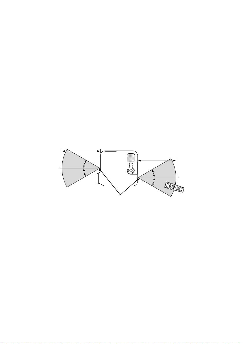
Operating Range
7m/22 feet
˚
30
˚
30
7m/22 feet
˚
30
˚
30
Remote sensor on the
Remote control
projector cabinet
• The infrared signal operates by line-of-sight up to a distance of about
22 feet/7 m and within a 60-degree angle of the remote sensor on the
projector cabinet.
• The projector will not respond if there are objects between the re-
mote control and the sensor, or if strong light falls on the sensor.
Weak batteries will also prevent the remote control from properly
operating the projector.
E-20
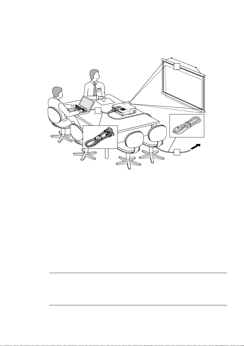
INSTALLATION AND CONNECTIONS
This section describes how to set up your projector and how to connect
video and audio sources.
1
2
3
To the wall outlet.
Your projector is simple to set up and use. But before you get started, you
must first:
z Set up a screen and the projector.
x Connect your computer or video equipment to the projector. See page E-
27.
c Connect the supplied power cable. See page E-35.
NOTE: Ensure that the power cable and any other cables are disconnected
before moving the projector.
When moving the projector or when it is not in use, cover the lens with the lens
cap.
E-21

INSTALLATION AND CONNECTIONS ⬎ Setting Up the Screen and theProjector
Setting Up the Screen and the Projector
Selecting a Location
The further your projector is from the screen or wall, the larger the image.
The minimum size the image can be is approximately 30" (0.8 m) measured diagonally when the projector is roughly 4 feet (1.3 m) from the wall
or screen. The largest the image can be is 500" (12.7 m) when the projector is about 80.83 feet (24.64 m) from the wall or screen. Use the drawing
below as a guide.
Screen size (Unit: cm/inch)
406.4(W)
⳯304.8(H)/160"(w)
81.3(W)
61.0(W)
⳯45.7(H)/24"(W)
243.8(W)
203.2(W)
⳯152.4(H)/80"(W)
162.6(W)
⳯121.9(H)/64"(W)
121.9(W)
⳯91.4(H)/48"(W)
⳯61.0(H)/32"(W)
⳯18"(H)
Lens center
365.8(W)
⳯274.3(H)/144"(W)
304.8(W)
⳯228.6(H)/120"(W)
⳯182.9(H)/96"(W)
⳯72"(H)
⳯60"(H)
⳯48"(H)
⳯36"(H)
⳯24"(H)
40"
30"
⳯90"(H)
60"
⳯108"(H)
80"
⳯120"(H)
Screen size
200"
180"
150"
120"
100"
1.3/4.3
(1.0/3.3)
1.7/5.6
2.6/8.5
(1.3/4.3)
(2.0/6.6)
3.5/11.5
(2.7/8.9)
4.4/14.4
(3.4/11.2)
NOTE: Values in parentheses for LT240K.
E-22
5.3/17.4
6.6/21.7
(4.1/13.5)
Distance (Unit: m/feet)
(5.2/17.1)
7.9/25.9
(6.2/20.34)
8.8/28.9
(6.9/22.6)
INSTALLATION AND CONNECTIONS ⬎ Setting Up the Screen and theProjector
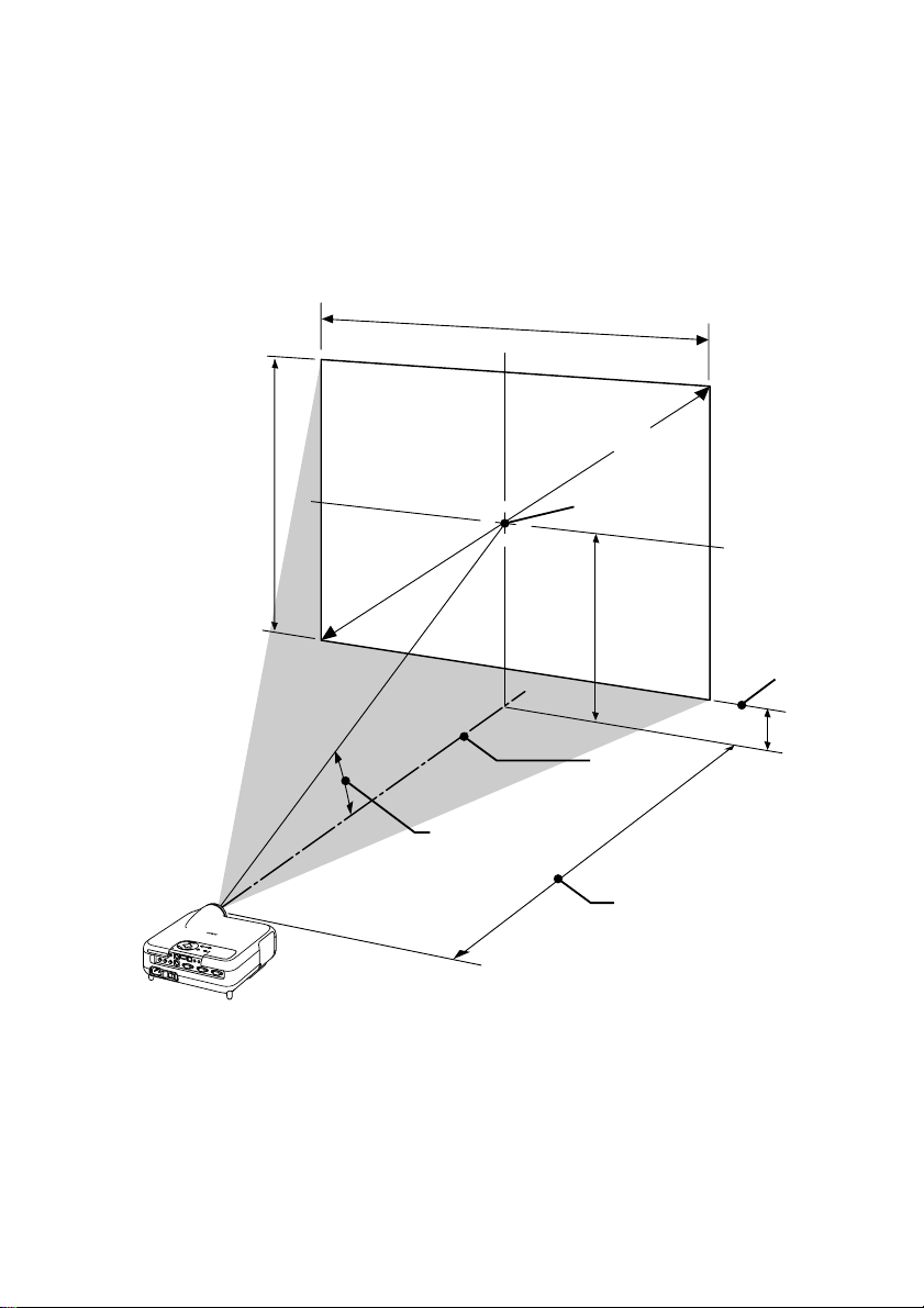
Throw Distance and Screen Size
The following shows the proper relative positions of the projector and screen.
Refer to the table to determine the position of installation.
Distance Chart
Screen Width
Screen Diagonal
Screen Height
Throw Angle (움)
Screen center
(B)
Lens Center
Throw Distance (C)
B = Vertical distance between lens center and screen center
C = Throw distance
D = Vertical distance between lens center and bottom of screen
α = Throw angle
Screen Bottom
(D)
E-23

INSTALLATION AND CONNECTIONS ⬎ Setting Up the Screen and theProjector
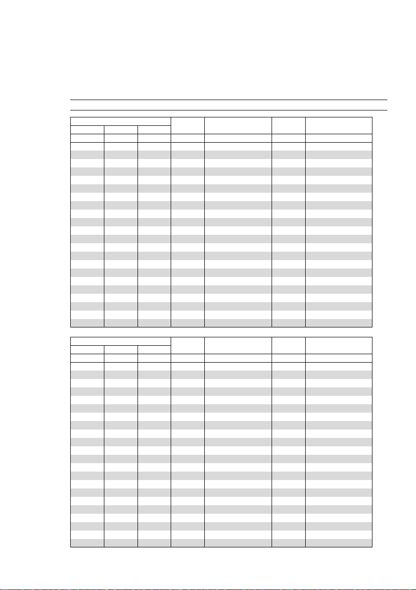
8761
B = Vertical distance between lens center and screen center
C = Throw distance
D = Vertical distance between lens center and bottom of screen
α = Throw angle
NOTE: Distances may vary +/-5%.
Screen Size B C
Diagonal Width Height
inch
30
40
60
67
72
80
84
90
100
120
150
180
200
210
240
261
270
300
350
400
450
500
inch
24
32
48
54
58
64
67
72
80
96
120
144
160
168
192
209
216
240
280
320
360
400
inch
18
24
36
40
43
48
50
54
60
72
90
108
120
126
144
157
162
180
210
240
270
300
inch
12.6
16.8
25.3
28.2
30.3
33.7
35.4
37.9
42.1
50.5
63.2
75.8
84.2
88.4
101.1
109.9
113.7
126.3
147.4
168.5
189.5
210.6
Wide – Tele
inch
46.4 – 57.0
62.4 – 76.4
94.5 – 115.3
105.8 – 128.9
113.8 – 138.6
126.6 – 154.1
133.0 – 161.9
142.7 – 173.6
158.7 – 193.0
190.8 – 231.8
239.0 – 290.1
287.1 – 348.4
319.2 – 387.2
335.3 – 406.7
383.4 – 464.9
417.1 – 505.7
431.6 – 523.2
479.7 – 581.5
560.0 – 678.6
640.2 – 775.7
720.5 – 872.9
800.7 – 970.0
inch
3.6
4.8
7.3
8.1
8.7
9.7
10.2
10.9
12.1
14.5
18.2
21.8
24.2
25.4
29.1
31.6
32.7
36.3
42.4
48.5
54.5
60.6
D
Wide – Tele
degree
15.2 - 12.5
15.1 - 12.4
15.0 - 12.4
14.9 - 12.3
14.9 - 12.3
14.9 - 12.3
14.9 - 12.3
14.9 - 12.3
14.9 - 12.3
14.8 - 12.3
14.8 - 12.3
14.8 - 12.3
14.8 - 12.3
14.8 - 12.3
14.8 - 12.3
14.8 - 12.3
14.8 - 12.3
14.8 - 12.3
14.7 - 12.3
14.7 - 12.3
14.7 - 12.2
14.7 - 12.2
α
Screen Size B C
Diagonal Width Height
mm
762
1016
1524
1702
1829
2032
2134
2286
2540
3048
3810
4572
5080
5334
6096
6629
6858
7620
8890
10160
11430
12700
mm
610
813
1219
1361
1463
1626
1707
1829
2032
2438
3048
3658
4064
4267
4877
5304
5486
6096
7112
8128
9144
10160
mm
457
610
914
1021
1097
1219
1280
1372
1524
1829
2286
2743
3048
3200
3658
3978
4115
4572
5334
6096
6858
7620
mm
321
428
642
716
770
855
898
962
1069
1283
1604
1925
2139
2246
2567
2792
2888
3209
3744
4279
4814
5349
1178 - 1448
1586 - 1942
2401 - 2928
2686 - 3274
2890 - 3520
3216 - 3915
3379 - 4113
3624 - 4409
4032 - 4902
4847 - 5889
6070 - 7369
7293 - 8849
8108 - 9836
8516 -10329
9739 -11810
10595 -12846
10962 -13290
12185 -14770
14223 -17237
16261 -19704
18299 -22171
20338 -24638
E-24
Wide – Tele
mm
D α
mm
92
123
184
206
221
246
258
277
307
369
461
554
615
646
738
803
831
923
1077
1231
1385
1539
Wide – Tele
degree
15.2 - 12.5
15.1 - 12.4
15.0 - 12.4
14.9 - 12.3
14.9 - 12.3
14.9 - 12.3
14.9 - 12.3
14.9 - 12.3
14.9 - 12.3
14.8 - 12.3
14.8 - 12.3
14.8 - 12.3
14.8 - 12.3
14.8 - 12.3
14.8 - 12.3
14.8 - 12.3
14.8 - 12.3
14.8 - 12.3
14.7 - 12.3
14.7 - 12.3
14.7 - 12.2
14.7 - 12.2
INSTALLATION AND CONNECTIONS ⬎ Setting Up the Screen and theProjector
8760
B = Vertical distance between lens center and screen center
C = Throw distance
D = Vertical distance between lens center and bottom of screen
α = Throw angle
NOTE: Distances may vary +/-5%.
Screen Size B C
Diagonal Width Height
inch
30
40
60
67
72
80
84
90
100
120
150
180
200
210
240
261
270
300
350
400
450
500
inch
24
32
48
54
58
64
67
72
80
96
120
144
160
168
192
209
216
240
280
320
360
400
inch
18
24
36
40
43
48
50
54
60
72
90
108
120
126
144
157
162
180
210
240
270
300
inch
12.6
16.8
25.2
28.1
30.2
33.6
35.3
37.8
42.0
50.4
63.0
75.6
84.0
88.2
100.8
109.7
113.4
126.1
147.1
168.1
189.1
210.1
Wide – Tele
inch
35.7 - 43.4
48.2 - 58.4
73.2 - 88.5
81.9 - 99.0
88.1 - 106.5
98.1 - 118.6
103.1 - 124.6
110.6 - 133.6
123.1 - 148.6
148.1 - 178.7
185.5 - 223.8
223.0 - 268.9
248.0 - 298.9
260.5 - 314.0
297.9 - 359.1
324.1 - 390.6
335.4 - 404.1
372.8 - 449.2
435.3 - 524.4
497.7 - 599.6
560.1 - 674.7
622.5 - 749.9
inch
3.6
4.8
7.2
8.0
8.6
9.6
10.1
10.8
12.0
14.4
18.0
21.6
24.0
25.2
28.8
31.4
32.4
36.1
42.1
48.1
54.1
60.1
D
Wide – Tele
degree
19.4 - 16.2
19.2 - 16.0
19.0 - 15.9
19.0 - 15.9
18.9 - 15.8
18.9 - 15.8
18.9 - 15.8
18.9 - 15.8
18.8 - 15.8
18.8 - 15.8
18.8 - 15.7
18.7 - 15.7
18.7 - 15.7
18.7 - 15.7
18.7 - 15.7
18.7 - 15.7
18.7 - 15.7
18.7 - 15.7
18.7 - 15.7
18.7 - 15.7
18.7 - 15.7
18.6 - 15.7
α
Screen Size B C
Diagonal Width Height
mm
762
1016
1524
1702
1829
2032
2134
2286
2540
3048
3810
4572
5080
5334
6096
6629
6858
7620
8890
10160
11430
12700
mm
610
813
1219
1361
1463
1626
1707
1829
2032
2438
3048
3658
4064
4267
4877
5304
5486
6096
7112
8128
9144
10160
mm
457
610
914
1021
1097
1219
1280
1372
1524
1829
2286
2743
3048
3200
3658
3978
4115
4572
5334
6096
6858
7620
mm
320
426
640
715
768
853
896
960
1067
1280
1601
1921
2134
2241
2561
2785
2881
3202
3735
4269
4803
5336
1224 - 1484
1858 - 2248
2080 - 2515
2239 - 2706
2493 - 3011
2620 - 3164
2810 - 3393
3127 - 3775
3761 - 4538
4713 - 5684
5664 - 6829
6298 - 7593
6615 - 7975
7567 - 9120
8233 - 9922
8518 -10265
9470 -11411
11055 -13320
12641 -15229
14227 -17138
15813 -19046
E-25
Wide – Tele
mm
907 - 1102
D α
mm
91
122
183
204
219
244
256
274
305
366
458
549
610
641
732
797
824
916
1068
1221
1374
1526
Wide – Tele
19.4 - 16.2
19.2 - 16.0
19.0 - 15.9
19.0 - 15.9
18.9 - 15.8
18.9 - 15.8
18.9 - 15.8
18.9 - 15.8
18.8 - 15.8
18.8 - 15.8
18.8 - 15.7
18.7 - 15.7
18.7 - 15.7
18.7 - 15.7
18.7 - 15.7
18.7 - 15.7
18.7 - 15.7
18.7 - 15.7
18.7 - 15.7
18.7 - 15.7
18.7 - 15.7
18.6 - 15.7
degree

INSTALLATION AND CONNECTIONS ⬎ Setting Up the Screen and theProjector
WARNING
* Installing your projector on the ceiling must be done by a qualified tech-
nician. Contact your dealer for more information.
* Do not attempt to install the projector yourself.
• Only use your projector on a solid, level surface. If the projector falls to
the ground, you can be injured and the projector severely damaged.
• Do not use the projector where temperatures vary greatly. The projector
must be used at temperatures between 41˚F (5˚C) and 95˚F (35˚C).
• Do not expose the projector to moisture, dust, or smoke. This will harm
the screen image.
• Ensure that you have adequate ventilation around your projector so
heat can dissipate. Do not cover the vents on the side or the front of the
projector.
Reflecting the Image
Using a mirror to reflect your projector's image enables you to enjoy a
much larger image. Contact your dealer if you need a mirror. If you're
using a mirror and your image is inverted, use the MENU and SELECT
buttons on your projector cabinet or buttons on your remote control to
correct the orientation. (See page E-95.)
E-26
INSTALLATION AND CONNECTIONS
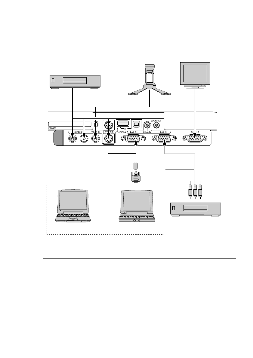
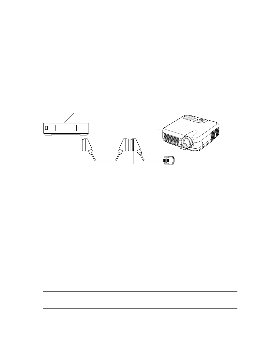
Making Connections
Wiring Diagram
VCR, DVD Player or
LaserDisc Player
To video, S-video, and audio inputs on the projector.
RGB Signal cable (supplied)
To mini D-Sub 15-pin connector on the projector. It is recommended that you use a commercially available distribution amplifier if connecting a signal cable longer than the supplied cable.
Macintosh
(Desktop type or notebook type)
IBM VGA or Compatibles
(Desktop type or notebook type)
Document Camera
Optional 15-pin-to-RCA
(female)⳯3 cable
(ADP-CV1)
Monitor
DVD Player
(with component output)
NOTE: When using with a notebook PC, be sure to connect between the projector
and the notebook PC before turning on the power to the notebook PC. In most
cases signal cannot be output from RGB output unless the notebook PC is turned
on after connecting with the projector.
* If the screen goes blank while using your remote control, it may be the result of
the computer's screen-saver or power management software.
* If you accidentally hit the POWER button on the remote control, wait 90 sec-
onds and then press the POWER button again to resume.
E-27
INSTALLATION AND CONNECTIONS ⬎ Making Connections
To connect SCART output (RGB)
Before connections: An exclusive SCART adapter (ADP-SC1) and a commercially available SCART cable are required for this connection.
NOTE:
•Audio signal is not available for this connection.
• The RGB IN 2 connector does not support SCART signal and Plug & Play.
Video equipment
such as DVD player
R
E
W
O
P
S
U
T
A
Y
T
B
S
D
N
A
P
T
M
S
A
N
L
O
T
N
E
M
N
G
I
L
A
T
S
U
J
D
A
O
T
C
N
E
A
U
L
C
A
E
D
C
R
R
A
U
C
-
O
C
S
P
R
E
T
N
E
T
C
E
L
E
S
U
N
E
M
Projector
To RGB IN 1
Commercially available SCART cable
Female
ADP-SC1
1. Turn off the power to the projector and your video equipment.
2. Use the ADP-SC1 SCART adapter and a commercially available
SCART cable to connect the RGB 1 input of your projector and a SCART
output (RGB) of your video equipment.
3. Turn on the power to the projector and your video equipment.
4. Use the RGB 1 button on the remote control to select the RGB 1 input.
5. Press the MENU button on the remote control to display the menu.
6. From the Advanced menu, select [Projector Options] → [Setup] → [Page
3] → [Signal Select RGB1] → [Scart].
SCART is a standard European audio-visual connector for TVs, VCRs
and DVD players. It is also referred to as Euro-connector.
NOTE: The ADP-SC1 SCART adapter is obtainable from your dealer in
Europe. Contact your dealer in Europe for more information.
E-28
INSTALLATION AND CONNECTIONS ⬎ Making Connections
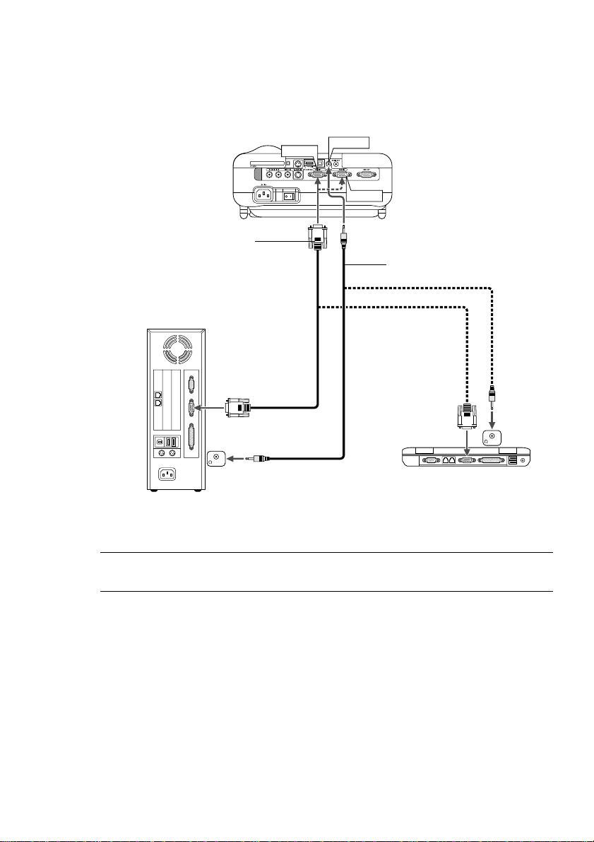
Connecting Your PC or Macintosh Computer
RGB IN1
RGB signal cable (supplied)
To mini D-Sub 15-pin connector on the
projector. It is recommended that you use
a commercially available distribution amplifier if connecting a signal cable longer
than the supplied one.
PHONE
IBM VGA or Compatibles (Desktop type)
or Macintosh (Desktop type)
AUDIO IN
RGB IN2
Audio cable (not supplied)
PHONE
IBM VGA or Compatibles (Notebook type) or Macintosh (Notebook type)
NOTE: For older Macintosh, use a commercially available pin adapter (not sup-
plied) to connect to your Mac's video port.
E-29

INSTALLATION AND CONNECTIONS ⬎ Making Connections
Connecting your PC or Macintosh computer to your projector will enable
you to project your computer's screen image for an impressive presentation.
To connect to a PC or Macintosh, simply:
1. Turn off the power to your projector and computer.
2. Use the supplied signal cable to connect your PC or Macintosh to the
projector.
3. Turn on the projector and the computer.
4. If the projector goes blank after a period of inactivity, it may be caused
by a screen saver installed on the computer you've connected to the projector.
E-30
 Loading...