

Page 1
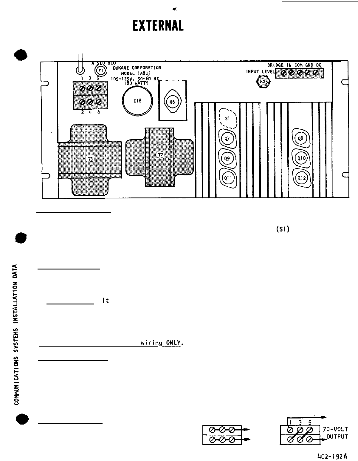
CONNECTIONS
FUSE
DUKANE MODEL 1A803
( AND
THERMOSTAT) -
100-WATT
POWER AMPLIFIER
One
4-ampere
addition ,
I n
circuit and which is fastened to one of the large transistor heatsinks; any over-heating
of the output transistors will open th e
close d
INSTALLATION NOTES
The
input, single-ended .
Amplifier Ground
console
(or coldwater pipe).
ware, place an outside-toothed lockwasher under the head of one of the mounting screws.
Clas s
power wiring must be Clas s I
EXTERNAL CONNECTIONS
Make
to this amplifier AFTER external connections have been made and are checked to be free
of any short circuits.
automatically y
DuKane
metalware which is, in turn,
II I
ALL external connections to screw terminals on rear of amplifier .
slow-blow fuse protects the primary AC power circuit for this amplifier.
there is a temperature-controlled (thermostat) switch
primary :
as the thermostat temperatur e comes
-
Model 1A803
- is good practice to ground the amplifier chassis to the rack or
wiring is permissible for 25-volt o r
100-Watt
See paragraph titled “INPUT LEVEL”
To be sure grounding exists between the amplifier and the metal-’
-
Power Amplifier provides
connected to conduit and electrical system ground
power circuit, and the power circuit is
down.
full-rated output with 0.4 volt
on next page.
70-volt t
level output (speaker line) .
in the AC power
Connect AC power
AC
A conventional speaker system of up to 100 watts ,
matching transformers can be connected to this amplifier .
OUTPUT CONNECTIONS
Connect jumper wires between screw terminals
and connect speaker line as shown at right
-
including appropriate speaker-to-line
I35
246
n
See chart at top of next page.
25-VOLT
OUTPUT
246
Page 2
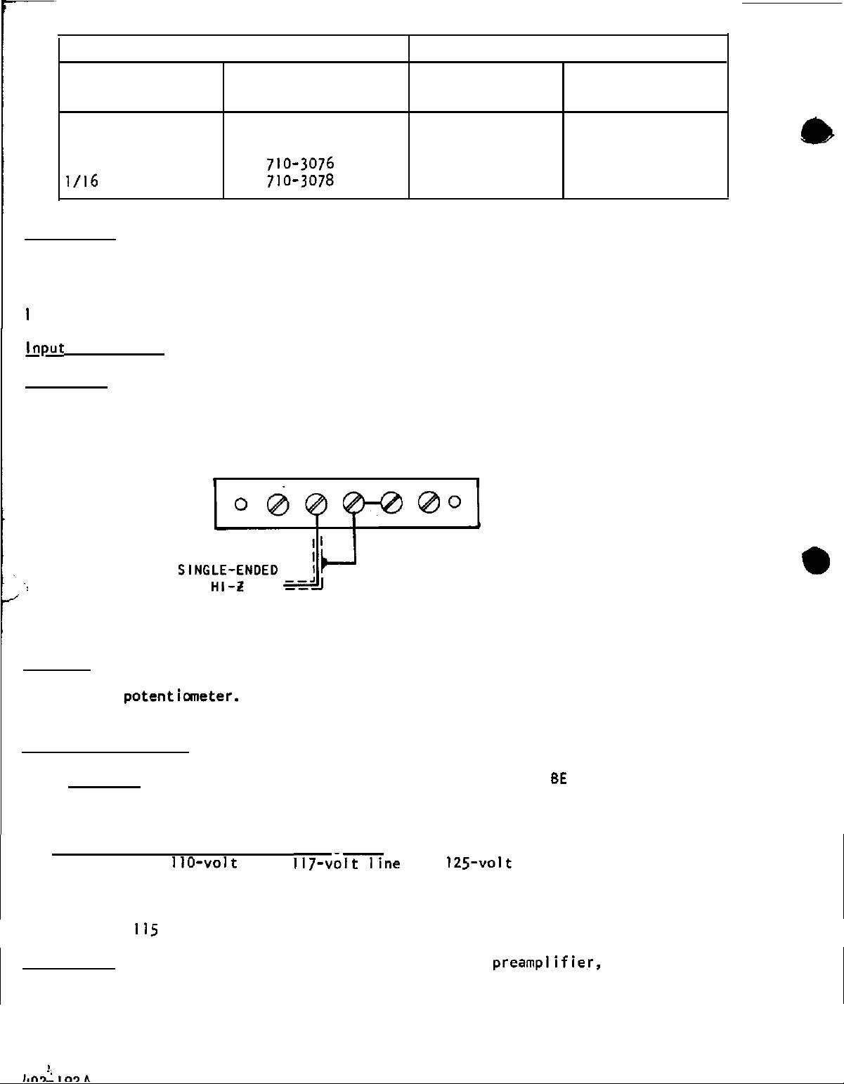
70-VOLT SPEAKER LINE
25-VOLT SPEAKER LINE
SPEAKER POWER
DUKANE TRANSFORMER SPEAKER POWER
LEVEL
15 to 50 watts
5 to 30 watts
1/2 2
to 4 watts
PART NO.
710-3070
710-3071
1/2 2
LEVEL
5 to 20 watts
to 2 watts
DUKANE
TRANSFORMER
PART NO.
710-3077
710-3075
to l/2 watt
INPUT LEVEL
watts of output power with this amplifier.
accommodate
(to 0 VU) for actual amplifier installation and operation .
Not more than 0.4 volt rms (sine wave) input is required to obtain full
However, it is recommended that, in order to
the complex wave form of program material ,
th e input should be lowered 8
Set INPUT LEVEL potentiometer
for 0 level indicated on VU meter (on 25-volt line. IO volts rms sine wave
ine, 28 volts
connections are made at screw terminals labeled
COM to GND
tween
“COM”
shield to preamplifier ground instead
rms).
In
some instances ,
and
“GND”
on the input terminal strip - amplifier
“IN"
and
“COM”,
shield to
it will be found desirable to disconnect the jumper be-
common
-
to reduce any hum pick-up . ALSO see paragraph
connected through
on the front of this sheet titled “Amplifier Ground”.
BRIDGE IN COM GNO DC
-
on
70-volt
“COM”.
dB
100
,
OUTPUT
An appropriate resisto r may be connected between the screw terminals labeled
BRIDGING
“BRIDGE” and
“IN ”
in instances where input level is too high to be easily reduced by
INPUT LEVEL
6
dB;
a
I-megohm
resistor would be inserted where input might exceed 10 volts.
AC POWER CONNECTIONS
IMPORTANT -Before connecting AC power to this amplifier,
HIGH- IMPEDANCE
A
lOO,OOO-ohm,
l/2-watt resistor will reduce input level by
-
INPUT
C ONNECTIONS.
SURE that correct
output load (speakers correctly matched to speaker line) and input
connections are properly made to terminals on this amplifier.
AC power wiring mus t be Class I wiring ONLY.
primary taps for
line,
Power transformer in this amplifier
and
line. As supplied. the
has
117volt tap is connected . However, if line voltage is more than 120 volts, disconnect the
circuit breaker white wire connected at terminal lug for yellow-black transformer tap,
and connect circuit breaker wire to lug for red-black transformer tap .
is less than
volts , connect circuit breaker wire to white-black transformer tap.
DC TERMINAL -Auxiliary power is available for external
If line voltage
of 28 volts DC
at 50 milliamperes.
a
Page 3
Page 4
 Loading...