

Page 1

1.1 INTRODUCTION
SECTION
1
GENERAL INFORMATION
This manual provides installation and service information for the Dukane Model
lA731
In-Wall Amplifier, and the Dukane
manufactured by Dukane Corporation, St. Charles, Illinois 60174.
This manual is divided into three sections, as follows:
1.
General Information.
2.
Installation Information.
3. Service Information.
1.2 GENERAL DESCRIPTION
The Dukane Models
complete sound distribution systems providing standard 25-Volt or
input facilities for up to eight microphones, a radio tuner and phono input. These amplifiers have
a power output of 60-Watts and 120-Watts respectively. An Octave Filter
(436-408).
as options at the output for improved sound reproduction. Terminals are provided for each option.
1.3
TECHNICAL
Dual Microphone Expander
lA729
SPECIFICATIONS
and
lA731
120-Watt In-Wall Amplifier. These amplifiers are
transistorized in-wall amplifiers are designed for use as
70-Volt
(438-496),
(438-407).
and Remote Volume Controls may be installed
lA729
speaker line output,
60-Watt
Compressor
Power Output:
MODEL
MODEL
Distortion:
Less than 2% at rated power output,
from 40 to 20
Frequency Response:
40 to 20
at -6
Power Source:
105-125VAC.
Power Required:
MODEL
MODEL
lA729:
1A731:
kHz
dB
from full output on 70 V line.
1A729:
1A731:
60-Watts (RMS)
120-Watts (RMS)
kHz.
± 2dB. Envelopemeasured
single phase,
150 Watts at
put, 30
240
put, 40 Watts at idle.
Watts
Watts
at rated out-
50-60
Hz.
rated out-
at idle.
l-l
Fuse:
MODEL
MODEL
Noise Level:
Microphone: Better than 60dB down
Auxiliary: 75
Inputs:
(4) microphone, low impedance
(4) optional microphone inputs
(2)
auxiliary high impedance inputs
Input Sensitivity:
Microphone:
Auxiliary: 0.4 V rms.
1A729: (1)
1A731: (1) 3 Ampere Slo-Blo
1.5 Ampere Slo-Blo
300 uV
from
input.
dB
below output.
300 uV maximum.
reference
Page 2
2.3.2 Option Mounting
l
The option
connections. See individual packages for related literature.
2.3.3 Amplifier Mounting
Mount the amplifier chassis into the
(Figure 2-l). DO NOT install the Front Door Panel at this time.
2.4 ELECTRICAL CONNECTIONS
Cut all wires to length and strip wire ends as required. Make all external connections to screw
terminals on strips inside this unit (Figure 2-2).
2.4.1
Grounding
It is good practice to ground this amplifier to the
conduit
between the unit and the
packages
Connect AC power to this amplifier AFTER all connections have been completed.
and electrical ground (street-side of meter, cold water pipe). To be sure grounding exists
available have complete instructions and hardware included for mounting and
backbox,
backbox
place an outside toothed lockwasher under each mounting nut.
using the four
CAUTION
backbox
#10-24 studs and
which is, in turn, connected to the
nuts supplied
i
/
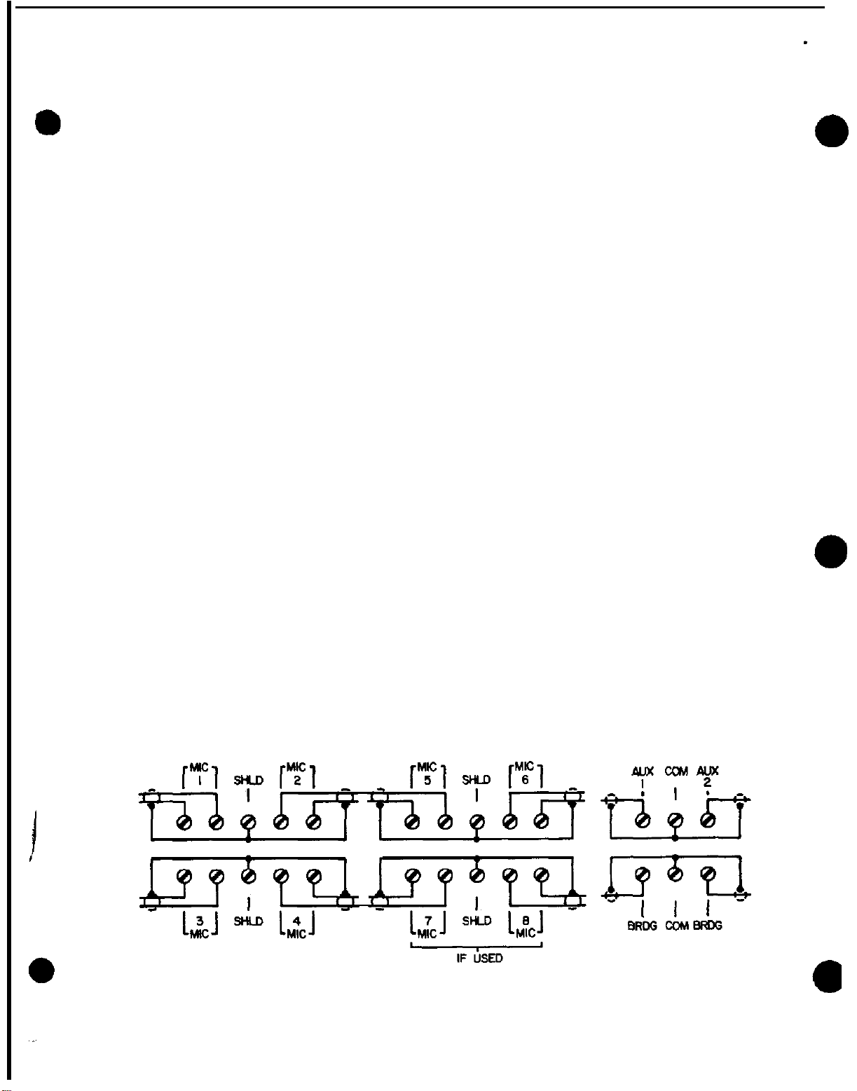
2.4.2 Balanced Microphone Inputs
Connect microphone center wire to MIC 1 and the shield side of the wire to the center terminal
marked SH (Figure
terminal. Use only shielded wires for microphone connections.
2-3).
Connect the second microphone to MIC 2, and the shield to the center
Figure 2-3. Balanced Mic Center Connections.
2-4
Page 3
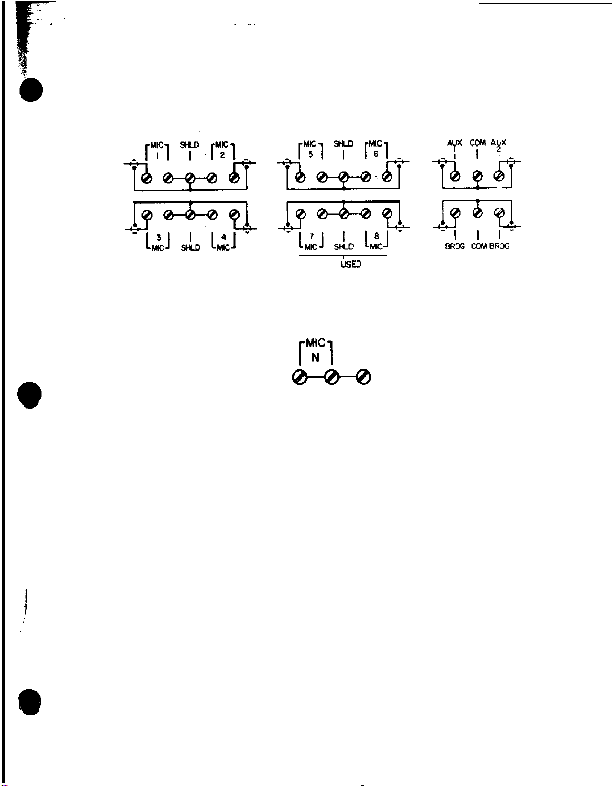
2.4.3 Single~ended Microphone Inputs
“N”
Connect the microphone center wire to a microphone input MIC
and the shield to the SHLD
center terminal with a jumper wire from SHLD to the unused MIC terminal (Figure 2-4).
IF
;SED
Figure 2-4. Single-Ended Mic Connections.
Connect all
unused
microphone inputs to the shield common terminal (Figure 2-5).
Figure 2-5.
Unused Mic Connections.
2.4.4 Auxiliary Program Input
Connect the auxiliary
program
input (from AM/FM tuner, phono, or tape player: to AUX
Connect the shield to the center terminal (Figure
NOTE
A second auxiliary program input can be connected to AUX 2 terminal with
the shield connected to center terminal. Either auxiliary program can
be selected by the front panel controls.
SHLD
1
2-3, 2-4).
then
2-5
Page 4
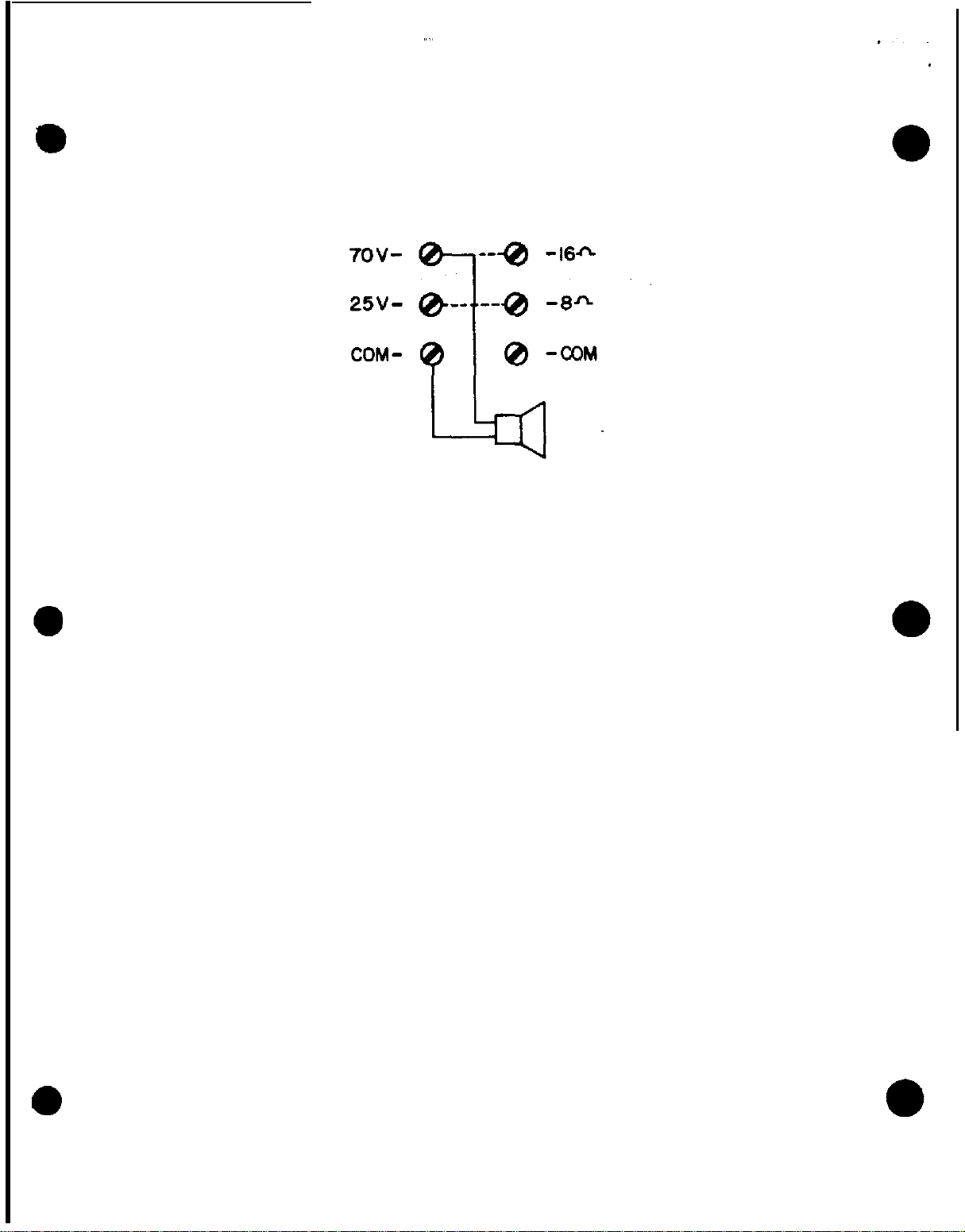
2.4.5 Output
For all
Ohms;
single-ended operation connect
25, 70
Volt) are used for present
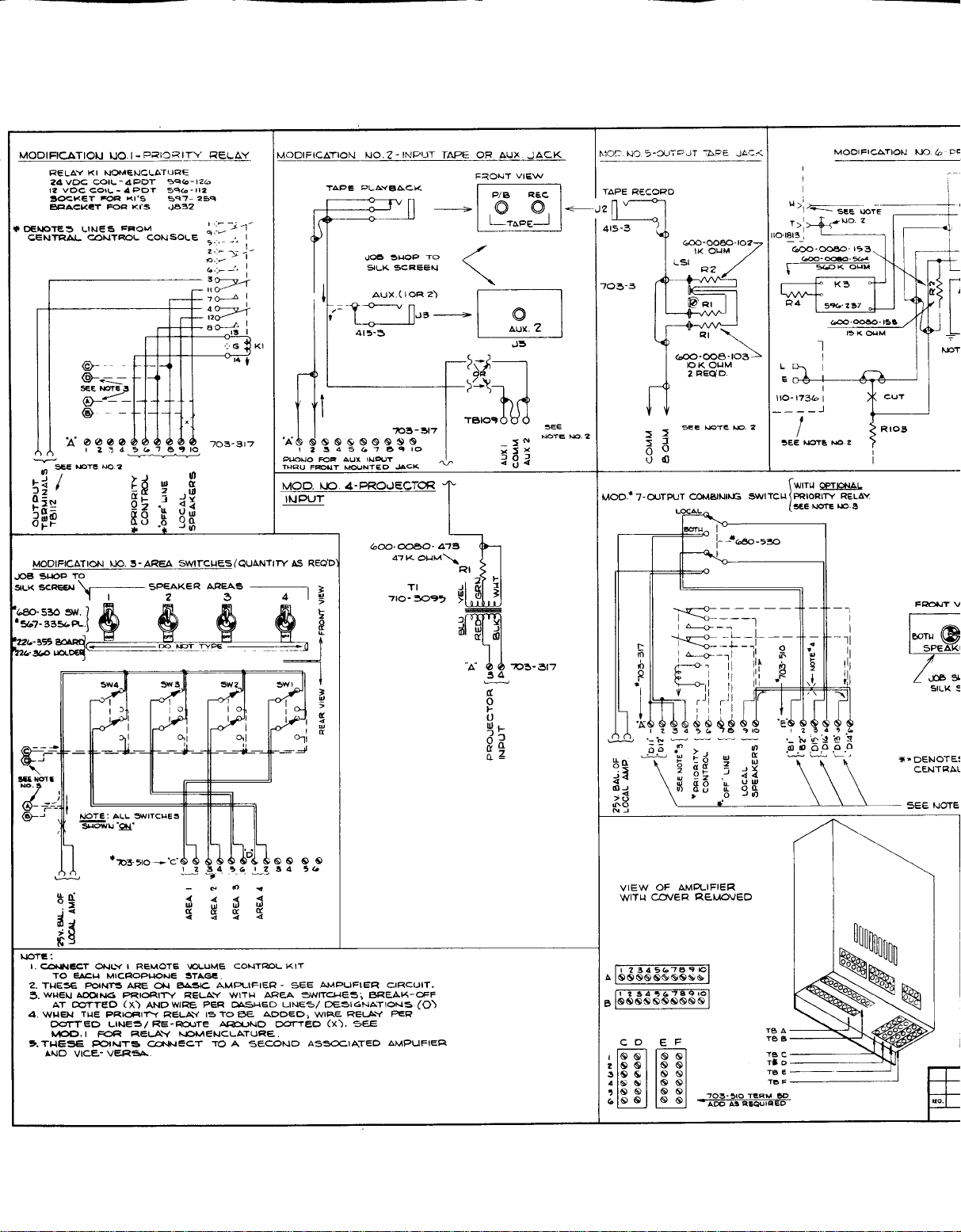
2.4.6 Amplifier
Certain
custom
for information.
Modifications
modifications
common to ground (Figure
output
circuits.
2-6).
Other terminals (8, 16
Figure 2-5. Speaker Line Connections.
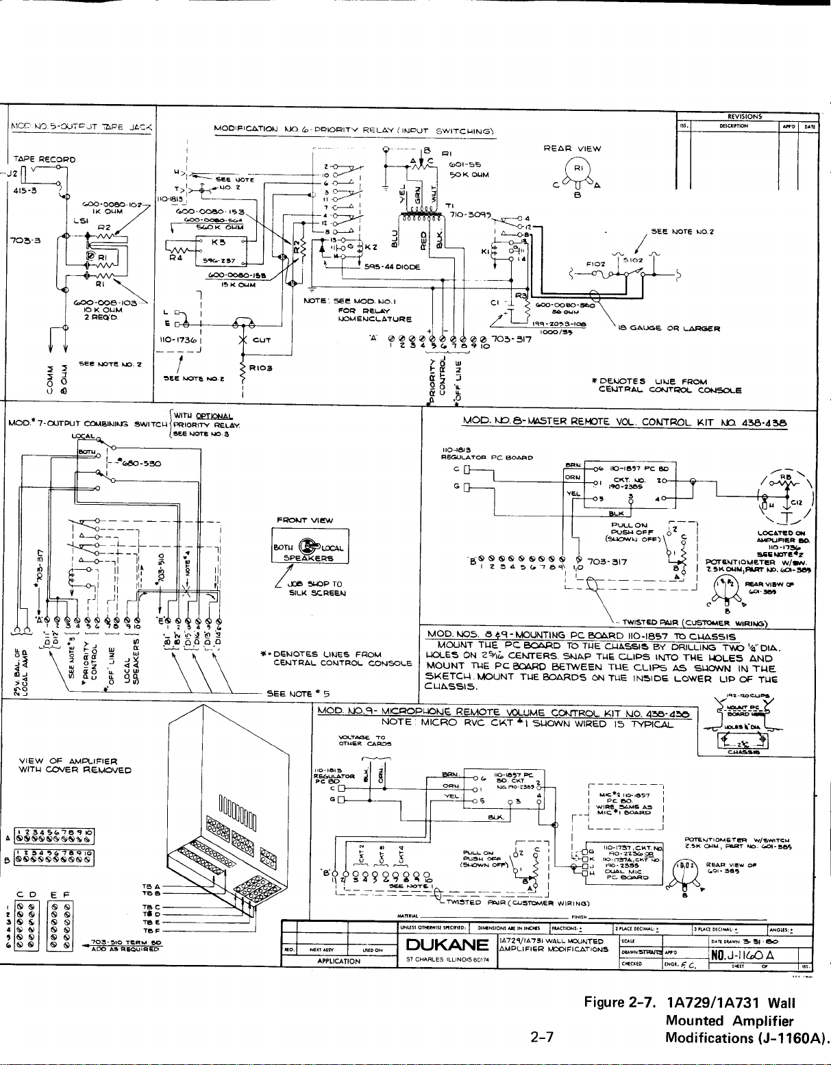
to the in-wall. amplifien can be made if desired. Refer to Figure, 2-7
2.4.7 Power
CAUTION
Set
all volume controls
up the
amplier without
to “0” before switching on AC Power. NEVER turn
an
output
load; e.g.. speakers (matched).
Plug in the 3-prong AC power plug into the receptacle on the handi-box within the backbox (Figure 2-l).
The SO-Watt amplifier is protected by an externally removable 1.5 Ampere slo-blo fuse and en
internal 3 Ampere slo-blo fuse. The 120-Watt amplifier is protected by an externally removable
3 Ampere slo-blo fuse
(Fig. 2-2).
and an internal 5 Ampere slo-blo fuse.
2-S
Page 5
Page 6
Page 7
Page 8
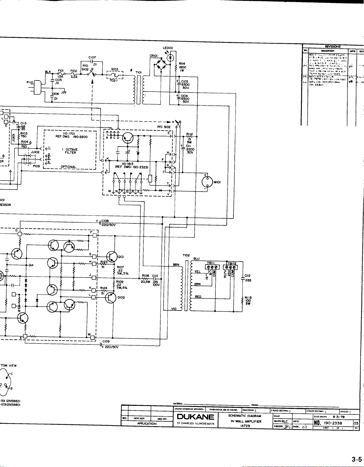
Repair Parts List - Chassis Mounted Parts
(1A729)
Legend Description Dukana Part No.
C103, C104
C105, C106,
Cl07
C108,
Cl09
Cl10
Cl11
C112
C113
CR101
F101
F102
LED101
Ml01
cl101
Q102
R101,
R102
R103,
R104
R105
R107,
R109
R108
R112
R113
R114
R115-R122
R123, R124
Capacitor,
Capacitor,
Capacitor,
Capacitor,
Capacitor,
Capacitor,
Capacitor,
65OOuF. 50WVDC,
.OluF, 14OOWV.
25OuF. 5OWVDC,
.015uF, lOOWVDC,
2OOOuF. 5OV.
.033uF, lOOV,
6.8uF. 35V,
Tant. Lytic
Lytic
Disc Car.
Lytic
Mylar
Lytic
Mylar
Rectifier
Fuse,
1.5
Ampere, 125V
Fuse, 3.2 Ampere,
125V,
3AG
Diode Light Emitting
Meter VU
Transistor, Power;
Transistor, Power;
Resistor, 1OOK Ohm,
2N5882
2N5880
l/2
Watt, 5%
Resistor, 750 Ohm, 1/2 Watt, 5%
Resistor, 910 Ohm,
Resistor,
.22
Ohm Wire, 5 Watt, 5%. WW
l/2
Watt, 5%
Resistor, 20 Ohm Wire, 3 Watt, 10%
Resistor, 15 Ohm, 5 Watt, 5%
Resistor, 100 Ohm, 5 Watt, 5%
Resistor, 1800 Ohm, 1 Watt, 5%
Resistor, 620 Ohm,
Resistor, 51 Ohm,
l/2
Watt, 5%
l/2
Watt, 5%
199-2030-658
199-9255
199-2048-257
199-4043-l 53
199-2048-208
199-4043-333
199-2036-685
595-74
320-010-0150
320-019-0320
230-8004-001
485-2014
720-39
720-109
600-0073-104
600-0073-751
600-0073-911
600-1050-R22
600-
1050-200
600-1050-150
600-1050-101
600-01 IO-182
600-0073-621
600-0073-510
S101
S102
S103
T101
T102
Switch, Toggle SPDT
Switch, AC Output
Thermostat
Transformer, Power
Transformer, Audio Output
Power Cord
Knob
Receptacle, Crimp Style, 3 Terminal
Receptacle
3-4
680-733
680-720
702-I
710-4239
710-2163
200-204
440-303
597-240-0003
597-240-0004
Page 9
Page 10
Page 11
Page 12
Page 13
Page 14
 Loading...