

Page 1
I
DUKANE
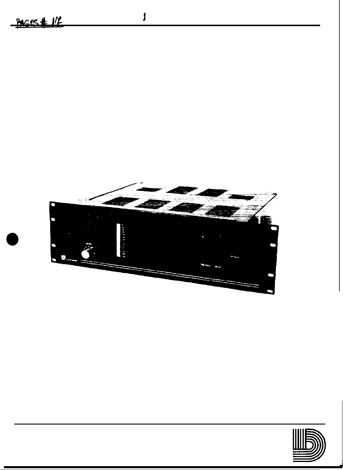
POWER AMPLIFIER
250 WATT DIRECT COUPLED
MODEL
1A2250
Installation, Operation and Service Manual
l
DUKANE CORPORATION
403-314
COMMUNICATIONS SYSTEMS DIVISION ST CHARLES. ILLINOIS 60174
Page 2

2
CONTENTS
l
l
Section
1
2
3
4
GENERAL INFORMATION
1.1
INTRODUCTION . . . . . . . . . . . . . .
1.2
GENERAL
1
.3
TECHNICAL
INSTALLATION INFORMATION
INTRODUCTION..
2.1
UNPACKING..
2.2
EQUIPMENT
2.3
POWER
2.4
EXTERNAL
2.5
OPERATING INFORMATION
3.1
CONTROLS
SERVICE INFORMATION
4.1 INTRODUCTION
DESCRIPTION
SPECIFICATIONS . . . . . . . . . . . . . . . . . . . . . . . . . . . . . . . . . . . . . . . . . . . . . . . . . . . . . . . . . . . . . . . . . . . . . .
...........................................................................................
..................................................................................................
MOUNTING
CONNECTIONS..
CONNECTIONS...........................................................................
AND
INDICATORS . . . . . . . . . . . . . . . . . . . . . . . . . . . . . . . . . . . . . . . . . . . . . . . . . . . . . . . . . . . . . . . . . . . . .
..,......._.._,,,._.,........................................................................
...............................................................................
................................................................................
Page
pAGE
. . . . . . . . . . . . . . . . . . . . . . . . . . . . . . . . . . . . . . . . . . . . . . . . . . . . . . . . . . . . . . . . . . . . . . . . . . . . . .
l-l
1-1
t-1
2-l
2-l
2-1
2-1
2-2
3-1
4-1
Figure
2-l
2-2
3-l
4-l
FIGURES
Description
AC Supply Input and Fuse Assembly
lA2250
1 A2250 Front Panel View
lA2250 Chassis
Rear
Panel
Mounted
View
. . . . . . . . . . . . . . . . . . . . . . . . . . . . . . . . . . . . . . . . . . . . . . . . . . . . . . . . . . . . . . . . . . . . . . . . . . . . . . . . . . . . . . . . . .
._._._.......................
Components and
. . . . . . . .
Circuit
.._...........................................
. . . . . . . . . . . . . . . . . . . . . . . . . . . . . . . . . . . . . . . . . . . . . . . . . . . .
Board
Locations . . . . . . . . . . . . . . . . . . . . . . . .
. . . . . . . . . . . . . . . . .
page
.
2-l
2-2
. . . . . . . .
3-l
4-1
ii
Page 3
1.1 INTRODUCTION
GENERAL
INFORMATION
This manual provides installation,
250 wan Direct Coupled Power Amplifier manufactured by the
Illinois 60174.
This manual is divided into four sections as follows:
General Information
1.
2. Installation Information
3. Operating Information
4. Service Information
1.2 GENERAL DESCRIPTION
The Dukane Model
gymnasiums, and in field applications where professional sound quality is required. Output level is
indicated by a VU light bar. The amplifier is protected from damage which could result from an
over temperature condition in the output stage circuitry. A
damage in case of a short circuit developing in the speaker line(s) served by the amplifier.
The amplifier may be operated with either unbalanced or balanced input. An optional input
plug-in transformer allows for balanced operation. The output of the amplifier can be either
unbalanced (direct coupled) or balanced. An optional plug-in transformer allows for balanced
output.
lA2250
Direct Coupled Power Amplifier is designed for use in auditoriums,
operating, and service information for the Model 1A2250
Dukane
foldback
Corporation, St. Charles,
circuit is employed to prevent
1.3 TECHNICAL SPECIFICATIONS
CONTINUOUS AVERAGE POWER OUTPUT:
250 watts.
HARMONIC DISTORTION:
Less than .05%
Less than 0.5% @ 1 kHz !@ rated output)
for transformer option.
FREQUENCY RESPONSE:
%2O,BCkY
25-20,OClB
SIGNAL TO NOISE RATIO:
Greater than
(20-20,BOB
INPUT SENSITIVITY:
1 volt rms
INPUT IMPEDANCE:
1Ok
ohms unbalanced,
tusing 3A23Dinputtransformer~.
LB
1
kHrf@
Hz, +2dB (direct coupled).
Hz,
-3dB,
+ldB (transformer).
-1OWB below rated output
Hz bandwidth).
@
1kHz for rated output.
rated output).
15k
ohms balanced
OUTPUT IMPEDANCE:
4 ohms direct unbalanced.
8 ohms (25 and
transformer option).
OUTPUT REGULATION:
Direct, 0.5dB no load to full load
Transformer,
1 kHz.
CONTROLS:
Volume Control.
AC Switch.
INDICATORS:
Power On LED.
:Over
POWER SOURCE:
l-l
Temperature LED.
Color Bar VU Graphic.
~12Ol24B
volts,
70.7V)
1dB
5o/BB
balanced (output
no load to full load
Hz.
@ IkHr.
@
Page 4

1.3 TECHNICAL SPECIFICATIONS (Continued)
POWER REQUIRED:
60 watts idle; 600 watts at full rated output.
TERMINATIONS:
Screw terminal strips.
FUSE:
6.25 amperes,
3.2 amperes,
26OV.
Slow Blow (120
-
or
-
25CV,
Slow Blow (240
FINISH:
Charcoal, baked enamel.
Vat).
Vat).
DIMENSIONS:
5-l/4” (13.3cm)
high, 19”
(48.3cm)
14” (36 cm) deep (without optiona l
Input Transformer);
deep (with
3A230).
15-3/4”
NET WEIGHT:
33 pounds (14.9 kg).
ASSOCIATED EQUIPMENT:
Model
3A230
Input Transformer.
Model 438-547 Output Transformer Kit.
wide,
3A230
(40.5 cm)
l-2
Page 5
SECTION 2
INSTALLATION INFORMATION
2.1 INTRODUCTION
This Section of the manual contains unpacking, mounting, and wiring instructions. The information
is arranged to facilitate an orderly installation.
information prior to beginning installation of the amplifier.
2.2 UNPACKING
Installers should have a good understanding of this
Examine the shipping carton and the amplifier.
attention of the distributor from whom it was purchased.
transportation company and place your damage claim without
inspected before it was packed and shipped from the Du kane Corporation.
2.3 EQUIPMENT MOUNTING
The
lA2250
the designated location using the four mounting screws provided.
2.4 POWER CONNECTIONS
The
lA2250
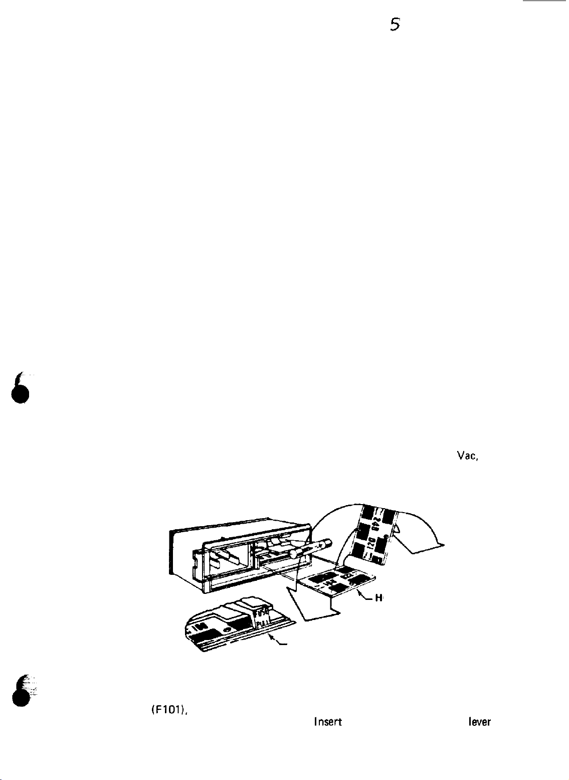
removable jumper card that allows the amplifier to operate on either 120 or 240
how the jumper card is installed in the
is designed for installation in a standard 19 inch rack or console. Mount the unit in
amplifier receives ac supply input via the
fuse
assembly.
If there is any damage to the unit, bring it to the
If this unit wasshipped to you, notify the
delay.
This amplifier was carefully
#321-42
Refer to Figure 2-l.
fuse assembly. This assembly has a
Vat.
depending on
Figure 2-1.
To replace fuse
lever
labeled FUSE PULL upward to pop the fuse.
(FlOl),
remove the ac plug, slide the plastic cover up to expose the fuse Move the
AC Supply Input and
FUSE
lnsart
2-l
OLE IN CARD
PULL LEVER
Fuse
Assembly
the new fuse, moving the
laver
downward.
Page 6
The voltage selection is visible on the jumper card, either 120 or 240 when the card is inserted into
the fuse assembly.
To change input voltage from 120 Vac to 240
Vac,
or vice versa, remove the fuse as explained
above, insert the point of a ball-point pen or pencil into the hole in the card and slide the card out
of the assembly.Turn the card so that the desired voltage shows on the upper left-hand side of the
card. Slide the card back into the assembly. Replace the fuse.
NOTE
Install the correct value of fuse
For 120
Vac
operation:
For 240 Vacoparation:
6.25 amperes, 25OV. Slow Blow.
3.2 amperes,
(F101)
as follows:
25OV.
Slow Blow.
2.5 EXTERNAL CONNECTIONS
TS1
and
TB101
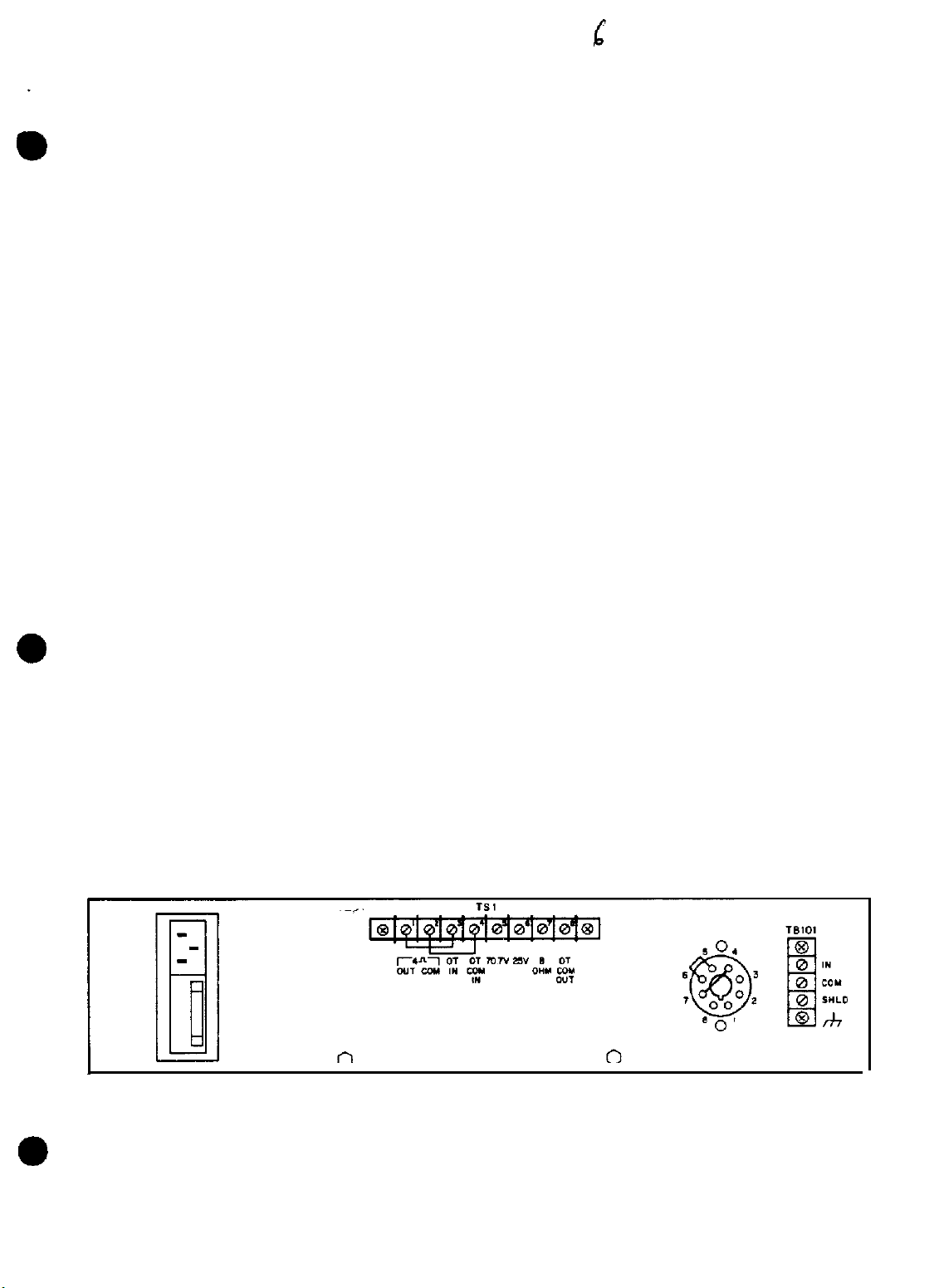
External connections are made to screw terminal strips
as shown in Figure 2-2.
When the optional output transformer 438-547 is used (balanced output), the jumpers between
terminals 1 and 3 and 2 and 4 on
Figure 4-l for location of
Pl.
When the output transformer is not used (unbalanced operation), the
TS1
must be in place. Plug the transformer into socket
Pl.
See
jumpers are not required.
TSl.
Make external output connections to terminal strip
connect to terminals 1 and 2. For balanced operation, the speakers connect to terminals
For unbalanced operation, the speakers
5, 6,
depending on the output desired, and terminal 8.
TB101
is for the input connections.
When the optional
3A230
Input Transformer is not used,
jumpers between terminals 4 and 7 and between terminals 5 and 6 of the octal socket must
place.
into the octal socket. Make external output connections to terminal strip
When the
3A230
is to be used for a balanced input, remove the jumpers and plug the
TS1,
as required for your
3A230
particular application.
I
Figure 2-2.
1A2250
Rear Panel View
or 7,
be
in
2-2
Page 7
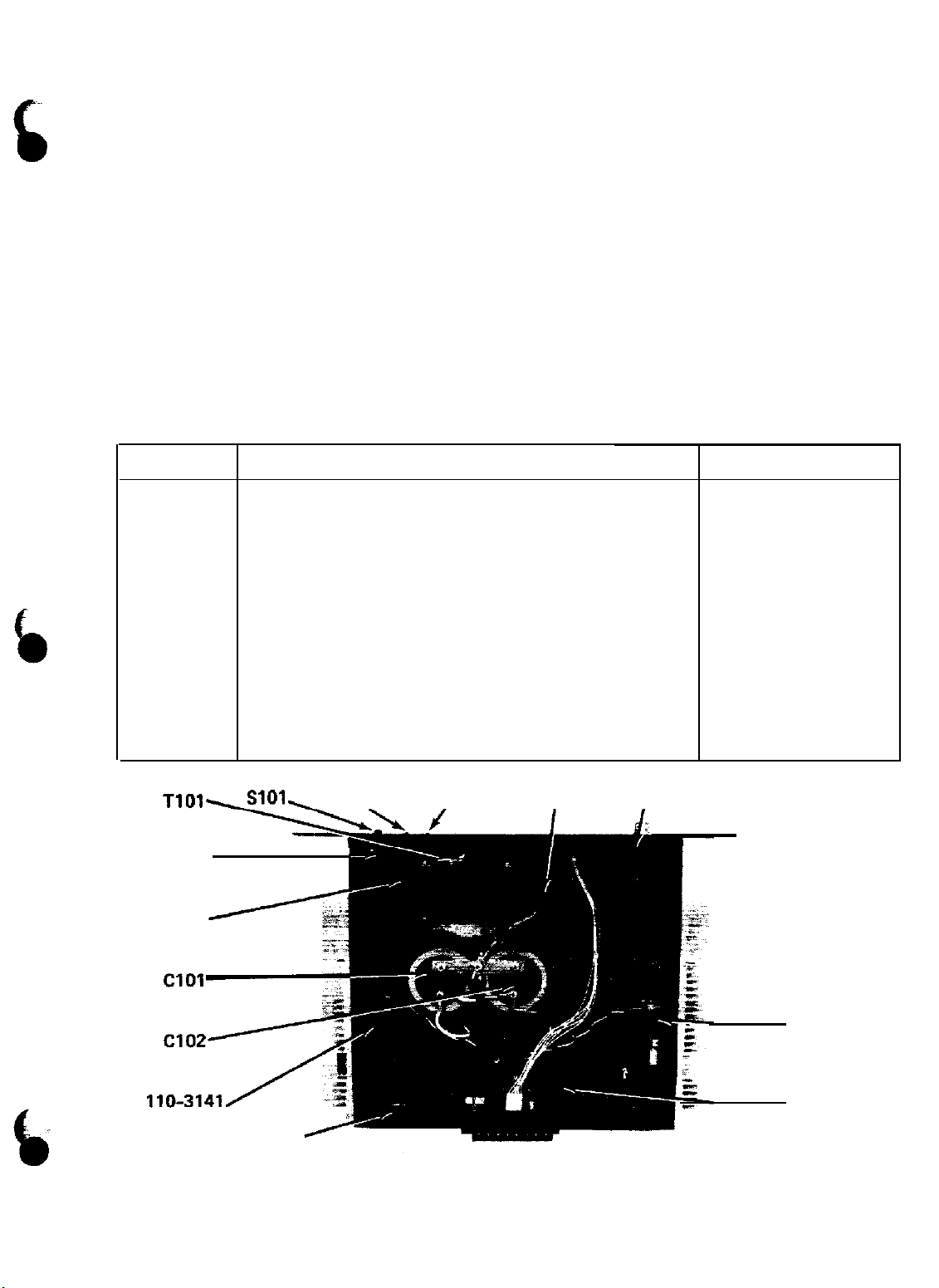
4.1 INTRODUCTION
SECTION 4
SERVICEINFORMATION
Standard electronic components are
Amplifier.
Dukane distributor, dealer, or from the factory. Any amplifier failure requiring circuit repairs
should be referred to an authorized dealer or repair facility in your area. Further damage can result
from improper repairs.
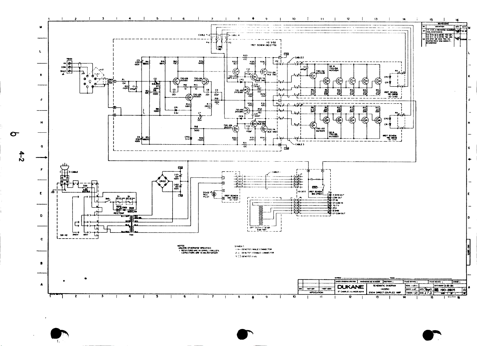
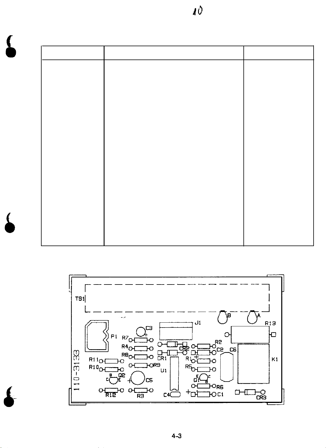
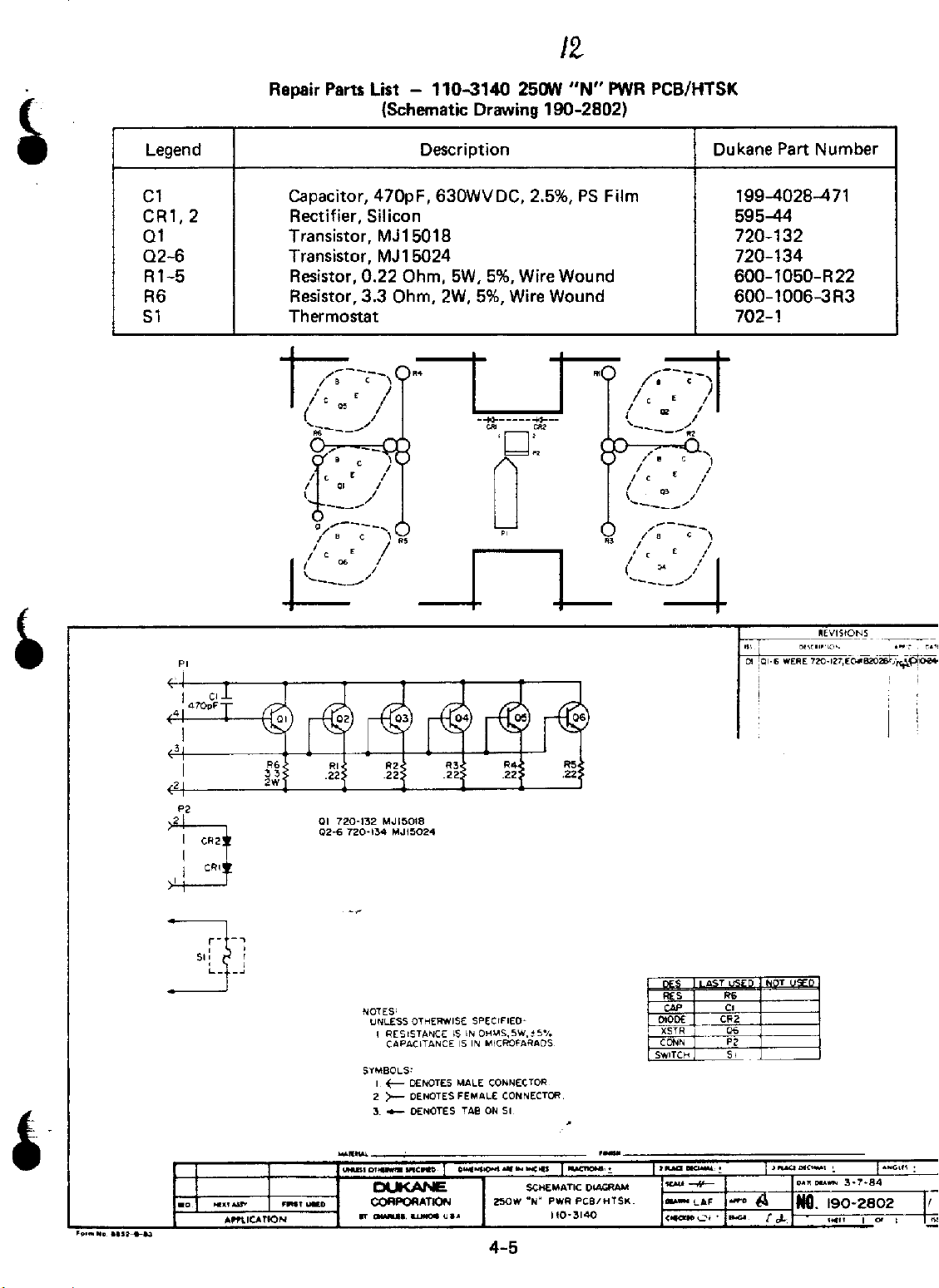
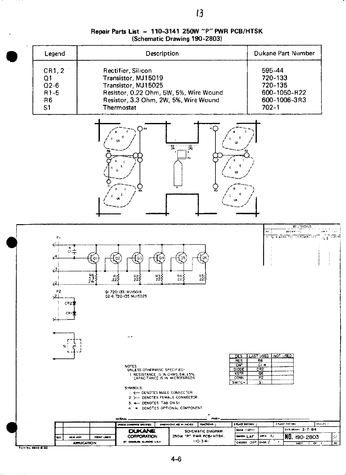
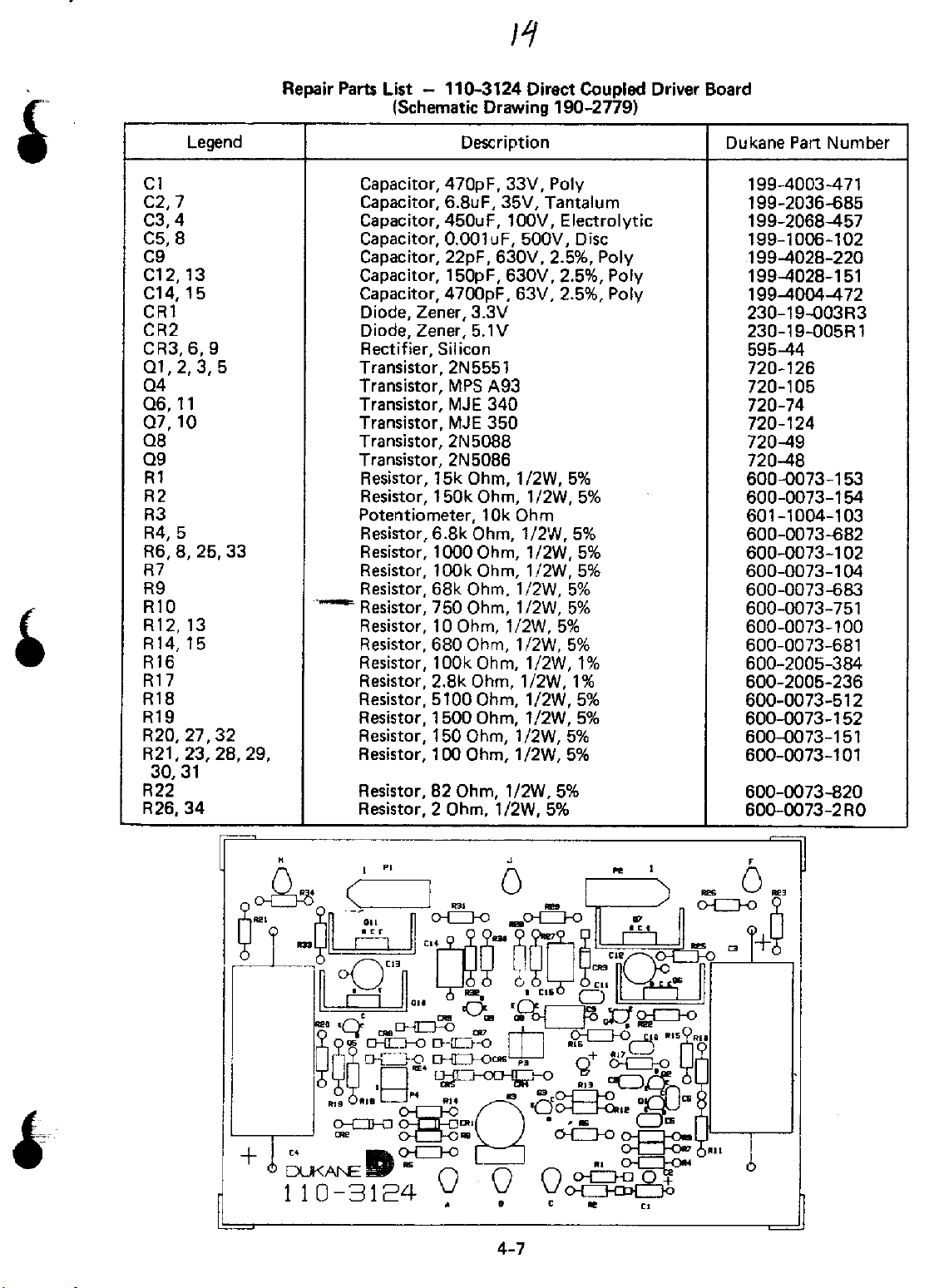
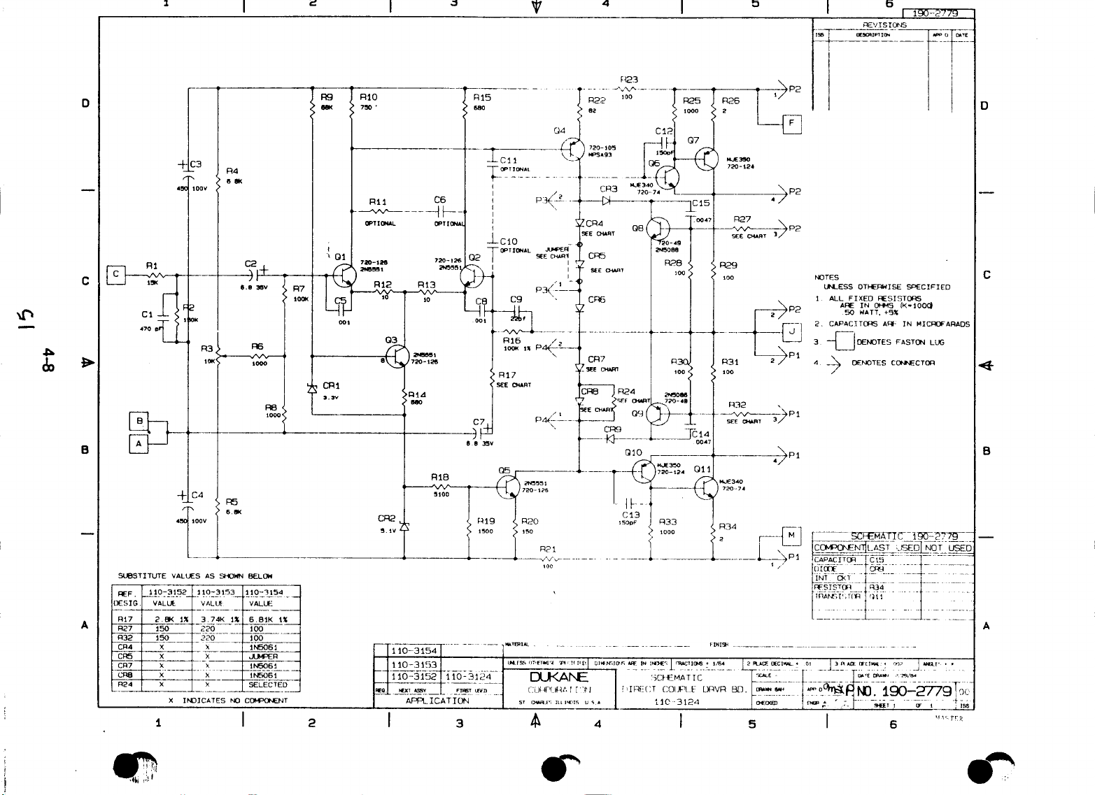
amplifier, the parts are shown first, followed by the parts location, and finally by the schematic
drawing.
Legend
C101,
CR101
CR102
DS101,
F101
F101
R101
R102
S101
T101
---
---
---
---
All replacement parts listed in the “Repair Parts List” are available through an authorized
For chassis mounted components and for each circuit board making up the
Repair Parts List -
102
102
Capacitor,
Rectifier, Silicon
Rectifier, Bridge, 400V
Diode, Light Emitting
Fuse,
Fuse,
Potentiometer,
Resistor, 6800 Ohm,
Switch, Rocker
Transformer, Power
Fuse Assembly, Voltage Selector/Receptacle
438-547 Output Transformer Kit (Optional)
129
Vac
240
Vac
15OOOuF,
6.25A.
3.2A,
25OV. Slow Blow (120
25OV. Slow Blow (240
Power Cord (Furnished)
Power Cord (Order Separately)
used
in the Dukane Model lA2250 250 Watt Direct Coupled
Chassis
(Schematic Drawing 190-28051
Description
lOOV, Electrolytic
10k
Ohm, Linear
5W.
5%
Mounted Components
Vac
operation) 320-010-0625
Vac
operation)
Dukane Part Number
199-9332
595-44
595-71
230-8005
320-010-0320
601-398
600-1050-682
680-818
710-4293
32142
710-2173
200-554
200-556
TTQT\STOT,
CR101
R102
BOARD
Figure 4-l.
F101
DS102
1A2250
DS101
CR102
R101
,
110-3140
BOARD
110-3124
BOARD
Chassis Mounted Components and Circuit Board Locations
4-l
Page 8
Page 9
45
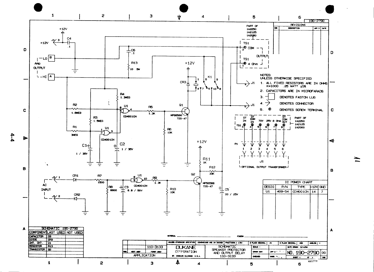
Repair Parts List - 1 lo-3133 Speaker Protector and Output Delay
(Schematic Drawing 190-2790)
Legend
Cl, 2
c3
c4
c5
C6
CRI-CR3
Kl
Q1,2
Rl
R2
R3
R4
R5,9
R6,10
R7
R6
R11
R12
R13
Capacitor, 1
Capacitor,
Capacitor,
Capacitor,
Capacitor,
Rectifier, Silicon
Relay,
i
Transistor, MPS6566
Resistor, 3
Resistor, 1.6
Resistor, 1.5
Resistor, 1.3
Resistor, 1300 Ohm,
Resistor,
Resistor, 1500 Ohm,
Resistor, 6800 Ohm,
Resistor, 1000 Ohm,
Resistor, 33k Ohm,
Resistor, 10 Ohm,
uF. 35V,
6.8uF. 5OV,
O.luF, 5OV.
33uF, 25V,
O.luF, 20OWVDC.
2Vdc,
Megohm, 1/4W,
1Ok
Description
Electrolytic 199-2054-105
Electrolytic
Ceramic 199-9327
Electrolytic
Electrolytic 199-4046-l
2 Form C 596-250
5%
Megohm. 1/4W,
Megohm, 1/4W,
Megohm, 1/4W,
1/4W,
Ohm,
1/4W,
1/4W.
1/4W.
1/4W,
1/4W,
5W,
5%
5%
5% 600-0039-l 35
5% 600-0039-132
5% 600-0039-l 03
5%
5% 600-0039-682
5% 600-0039-l 02
5%
5% 600-1050-100
Dukane Part Number
199-2062-685
199-2063-336
595-44
720-47
600-0039-305
600-0039-185
6006(139-l
600-0039-l 52
600-0039-333
04
55
Ul
Integrated Circuit, 40018 409-54
Page 10
Page 11
Page 12
Page 13
Page 14
Page 15
Page 16
 Loading...