

Page 1

KIA SKT210SY
TRAINING MANUAL
PROGRAMMING MANUAL -1-
Manual Iss 1
This document is based on information available at the time of its publication.
While efforts have been made to render accuracy to its content, the
information contained herein does not purport to cover all details or variations
in hardware and software, nor to provide every possible contingency in
connection with installation, operation, programming, and maintenance.
Features maybe described herein which are not present in all hardware and
software systems.
Dugard Ltd assumes no obligation of notice to holders of this document with
respect to changes subsequently made.
Dugard Ltd makes no representation or warranty, expressed, implied or
statutory with respect to, and assumes no responsibility for the accuracy,
completeness, sufficiency or usefulness of the information in the manual.
Page 2

PROGRAMMING MANUAL -2-
Cutting speed formula: ............................................................................................................................. 9
Vc= Cutting speed .................................................................................................................................... 9
D= Part standard diameter ....................................................................................................................... 9
n= Rpm limit. ............................................................................................................................................ 9
Machines must be at the X home position for turret indexing. .................................................................. 9
We advise you to enter workpiece zero at the beginning of the program. .............................................. 10
G10 P0 Z-80. .......................................................................................................................................... 10
How to prepare the machine for machining operations with transfer: ..................................................... 11
1st Determine workpiece zero and carry out the 1st machining stage .................................................... 11
G54 is programmed. ............................................................................................................................... 11
2nd Stop the machine and verify the dimension before doing the transfer. ............................................ 11
3nd Do the transfer and place the sub-spindle in working position. ........................................................ 11
4nd Stop the machine and determine workpiece zero before performing the 2nd machining stage G55 is
programmed. ........................................................................................................................................... 11
In this manual we will always refer to G codes type A. .......................................................................... 12
Comment:: .............................................................................................................................................. 12
These are notes included in the program. .............................................................................................. 12
These notes are totally optional, and it is up to the programmer to enter them or not. ........................... 12
These notes will be always placed in round brackets () in order to prevent the program reading them. . 12
T101 12
Here is shown that the tool to be used is in position 1 and a offset value of 01 is applied. ..................... 12
T0101 could be also entered, as the four mandatory characters are present, however, the first zero is
optional. ................................................................................................................................................... 12
Head rotation direction: .......................................................................................................................... 12
M3 head rotation direction forward ......................................................................................................... 12
M4 head rotation direction reverse ......................................................................................................... 12
M5 spindle stop ...................................................................................................................................... 12
If instructing the reverse from the forward direction or vice versa, the spindle must be stopped first. ... . 12
This is also valid for the sub spindle and live tools. ................................................................................ 12
G0 X150 Z100 ........................................................................................................................................ 12
Page 3

PROGRAMMING MANUAL -3-
Note that tool retraction in this example is to 150 mm on X+ and 100 mm on Z+ from work piece zero, and
not from chuck face, as no order for changing the position is given to work piece zero, which in this example
is maintained in the previous position. ..................................................................................................... 12
Line number (N10, N20...) ...................................................................................................................... 12
Line numbers are optional, and can be either entered or not. ................................................................. 13
G0 G40 G99 X45. Z0. M8 ....................................................................................................................... 13
As you can see, G codes are first placed and then X, Z and M codes. Codes can be also entered in the
following manner: G0 X45. Z0.G99 G40 M8 ............................................................................................ 13
Entering codes such as G96 and G50 in the same line is not permitted. ................................................ 13
In this example we assume that the part is rough machined. ................................................................. 16
As seen in this example, G2 is used to machine radii in clockwise direction and G3 in counterclockwise
direction. .................................................................................................................................................. 16
You can also see that G2 or G3 is first entered, then the end point, and finally the radius, .................... 16
Circular interpolation ............................................................................................................................... 17
As you can see, for the interpolation, you must know the point from which this interpolation will take place in
order to change radius direction (in this example on point X69.282 Z-60). .............................................. 17
Time delays are entered each time a slot is machined in order to improve the ..................................... 18
surface finish. ......................................................................................................................................... 18
G Code List ............................................................................................................................................ 21
M FUNCTIONS ...................................................................................................................................... 23
THREADING .......................................................................................................................................... 25
G32 for threading operations, always operate at fixed rpm (G97). ......................................................... 26
When retapping threads, do not release the work piece, do not change the speed and do not change the
start point. ................................................................................................................................................ 26
CANNED CYCLES ................................................................................................................................. 27
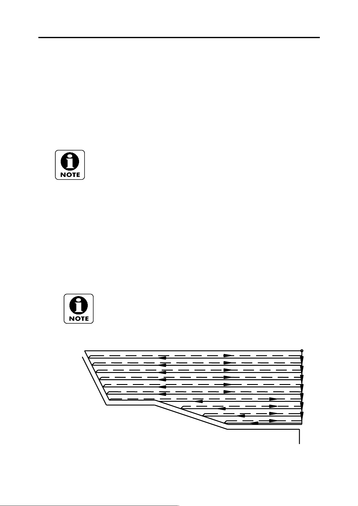
At the end of each cycle sequence the machine is always positioned in the position at which this cycle
sequence was started. The tool will be commonly located in the position used for rough machining. ..... 27
The profile allows changing X and Z direction. ....................................................................................... 27
At the end of each cycle sequence the machine is always positioned in the position at which this cycle
sequence was started. ............................................................................................................................. 27
The positioning allows changing X- and Z-axis direction. ....................................................................... 27
Page 4

PROGRAMMING MANUAL -4-
Same as the above one, excepting for the profile. .................................................................................. 28
IMPORTANT: Roughing cycles are without tool radius compensation. Because of this, higher allowances will
be specified for X and Z depending on tool radius. .................................................................................. 30
1. EXAMPLES OF CANNED CYCLES .................................................................................................... 31
Groove width or groove end point can be defined with a W code in this example (W27, that is, 30 – 3 of tool),
if tool is positioned on the right-hand would be (W-27). For either Z or W, tool width must be subtracted. 35
N5 G28 U0. V0. ...................................................................................................................................... 38
T505; 38
PROGRAMMING SIMPLIFICATION FUNCTIONS ................................................................................ 39
In theses cases, considering tool direction is most important. ................................................................ 39
The easier procedure is drawing a quadrant on the drawing and locate the degrees as shown on the above
diagram. .................................................................................................................................................. 39
All cycles end where they are started and, because of this, finishing positioning is done above the workpiece.
47
For control units with capability for machining profiles with X-axis direction reversal, the first block for defining
the profile must state the movement of the two axes. .............................................................................. 49
M98 Repetitions of a subprogram .......................................................................................................... 53
1- Stop the spindle (S1 and/or S2) by entering the command M5 (S1) or M115 (S2) before entering M43 or
M143 command. ..................................................................................................................................... 59
2- After activating M43 C-axis on G28 C0. must be entered . .................................................................. 59
3- After activating M143 A-axis on G28 A0. must be entered. ................................................................. 59
4- Before entering command M40 and M140, the powered tool must be stopped by entering command M15.
59
59
M160, M161 and M162 commands are only used on machines equipped with a sub-spindle (S). ......... 90
M160; ............ Speed synchronisation mode on. .................................................................................... 90
M161; ............ Phase and synchronisation mode off. ............................................................................. 91
M162; ............ Phase synchronisation mode on. .................................................................................... 91
1- For transferring a workpiece from main spindle to sub-spindle, main and sub-spindle speed must be
synchronised by means of M160 command. If the workpiece is transferred without activating the
synchronisation mode, damage of the workpiece could result. ................................................................ 91
Page 5

PROGRAMMING MANUAL -5-
2- For transferring an hexagonal bar, main and sub-spindle phase and speed must be synchronised by
means of M160 and M162 command, as otherwise the transfer operation will not be possible, although it is
recommended that if the part has been turned that you locate on the turned diameter so to achive any
squareness or concentricity tolerences. .................................................................................................. 91
3- M162 function can be also used for round parts, but considering that phase (and speed) synchronisation
time is longer and speed synchronisation time, using only M160 function is recommended when machining
round parts. ............................................................................................................................................. 91
Machining program. ................................................................................................................................ 92
G97 S50 M3; Main spindle rotates at 50 rpm ......................................................................................... 92
S50 M113;……………………..Sub spindle rotates at 50 rpm ................................................................. 92
M160; Synchronise spindles. .................................................................................................................. 92
M162; Synchronise spindle phase (if required). ...................................................................................... 92
Main and sub-spindle speed is synchronised to 50rpm .......................................................................... 92
M119; Sub-spindle chuck open. ............................................................................................................. 92
M151;……………………………Air blow on sub-spindle ......................................................................... 92
B-???; Sub-spindle is moved clear fo component (machine co-ordinates) ............................................. 92
G1 G98 B-??? F1500; Sub-spindle is moved over the workpiece at 1500 mm/min ................................ 92
M152; Air blow off sub-spindle. ............................................................................................................... 92
G28 B0; Sub-spindle is returned to reference point on B-axis ................................................................ 92
M161; Synchronisation mode is disabled ............................................................................................... 92
Machining program. ................................................................................................................................ 93
G97 S50 M3; Main spindle rotates at 50 rpm ......................................................................................... 93
S50 M113;………………………Sub spindle rotates at 50 rpm ............................................................... 93
M160; Synchronise spindles. .................................................................................................................. 93
M162; Synchronise spindle phase (if required). ...................................................................................... 93
Main and sub-spindle speed is synchronised to 50rpm .......................................................................... 93
M119; Sub-spindle chuck open. ............................................................................................................. 93
M151;……………………………Air blow on sub-spindle ......................................................................... 93
B-???; Sub-spindle is moved clear fo component (machine co-ordinates) ............................................. 93
G1 G98 B-??? F1500; Sub-spindle is moved over the workpiece at 1500 mm/min ................................ 93
Page 6

PROGRAMMING MANUAL -6-
G28 B0; Sub-spindle is returned to reference point on B-axis ................................................................ 93
G0 X50…………………………..Move off component. ............................................................................ 93
G28 U0………………………….Move turret home in X-axis. ................................................................... 93
G28 W0…………………………Move turret home in Z-axis. ................................................................... 93
M161; Synchronisation mode is disabled ............................................................................................... 93
G28 U0.: Turret home position in X ........................................................................................................ 94
M115: Sub-spindle is stopped ................................................................................................................ 94
G4 X0.5: Dwell for half a second ............................................................................................................ 94
M73; Parts catcher forward. ................................................................................................................... 94
Workpiece collector operates independently from turret position. .......................................................... 94
The B-axis co-ordinate value will be the G30 position, at which the workpiece is released from the sub-
spindle, without causing any interference with workpiece collector, turret, etc. ........................................ 94
G4 X0.5; Dwell for half a second ............................................................................................................ 94
M119; Open jaws on sub-spindle. .......................................................................................................... 94
G4 X3.; Dwell for three seconds to allow the part to be ejected fully. ..................................................... 94
M74; Parts catcher back. ........................................................................................................................ 94
G28 B0.; Sub spindle home. ................................................................................................................... 94
G4 X1.; Dwell for one second. ................................................................................................................ 94
G83 Example of face front drilling cycle (powered tool main spindle)…………………………………59
G83 Example of face front drilling (powered tool sub spindle)…………………………………………………..60
G87 Example of side drilling cycle (powered tool main spindle)………………………………………………..61
G87 Example of side drilling cycle (using main spindle and Y-axis)…………………………………………..62
G87 Example of side drilling cycle (powered tool sub spindle )………………………………………………...63
G184 Example of front face drilling cycle (powered tool main spindle)………………………………………...64
G185 Example of back face tapping cycle (powered tool sub spindle)………………………………………..65
G188 Example of side tapping cycle (powered tool main spindle)…………………………………………… ..66
G188 Example of side tapping cycle (powered tool main spindle using Y-axis)…………………………… ..67
Cylindrical interpolation………………………………………………………………………………………………68
Tool nose radius copensation and circular interpolation used with G112 polar coordinate interpolation….70
Example of machining a square using polar milling………………………………………………………………71
Example of machining a hexagon using polar milling…………………………………………………………….72
Page 7
PROGRAMMING MANUAL -7-
Milling using the Y-axis and C-axis…………………………………………………………………………………73
Milling usng the Y-axis and A-axis………………………………………………………………………………….76
Helical Interpolation using the Z-axis and Y-axis………………………………………………………………….79
Cylindrical Interpolation G107………………………………………………………………………………………..80
Tool nose radius compensation and circular interpolation used with G107 cylindrical interpolation…………82
Rectangle engrave example (cylindrical interpolation)…………………………………………………………….83
Rectangle with corner radii example (cylindrical interpolation)…………………………………………………..84
Part transfer (Billet)…………………………………………………………………………………………….........87
Part transfer (with part off).…………………………………………………………………………………….........87
Sub Spindle example…………………………..……………………………………………………………………..89
Part eject…………………………..……………………………………………………………………………........90
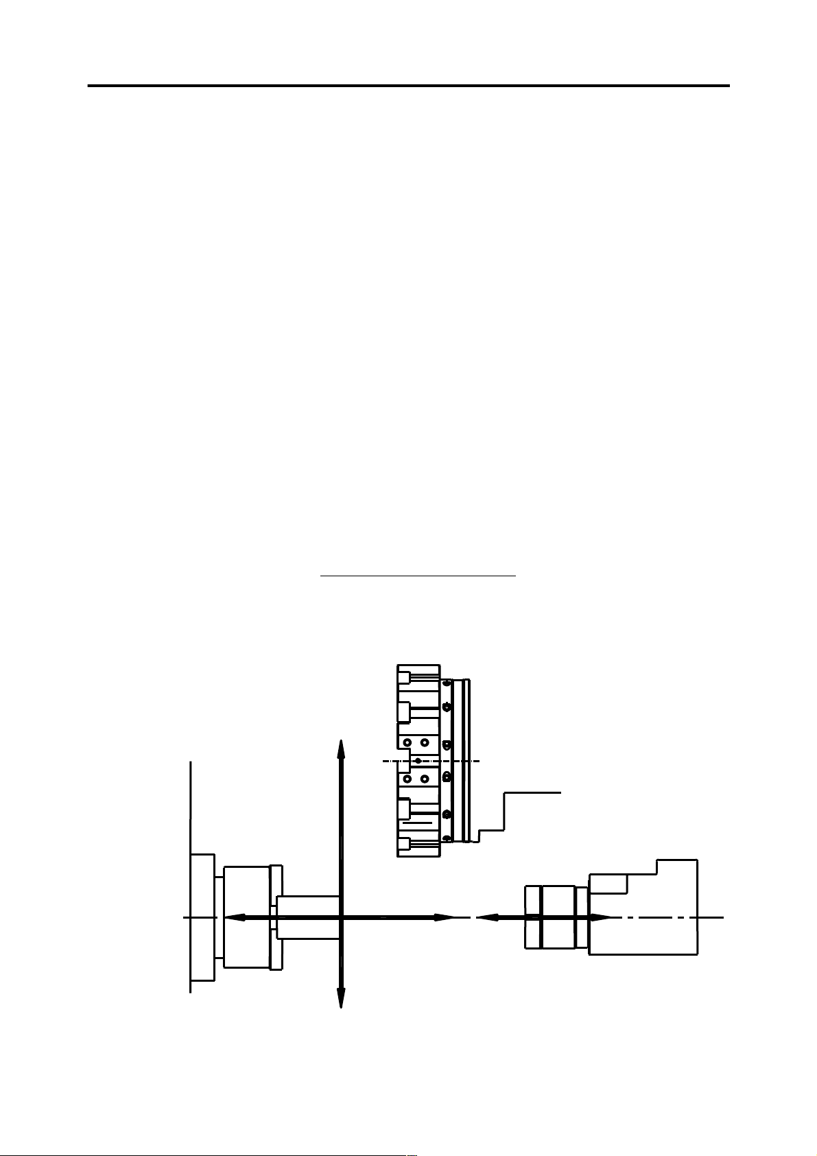
Machine axes
BASIC CONCEPTS
X+
Z- B- B+
Z+
X-
Page 8
C+
C-
A+
A-
PROGRAMMING MANUAL -8-
X-, Z- and B-axis and their respective positive and negative displacement directions are shown on
the above schematic diagram.
Y+ and Y- axis are not shown Y- is towards machine bed and Y+ away from the machine bed,
40mm+,40mm– to give stroke of 80mm. (machine needs to be on Y zero for turning operations).
As you can see, when workpiece zero reference point is located on workpiece end (most common
case), the positive direction is outside the workpiece, while the negative direction is on the
workpiece area to be machined (inside the workpiece).
Commonly, you will operate in the quadrant defined by X+ and Z-.
The machine will enter only in X- area for facing operations.
You may also operate X+ Z+ quadrant when the workpiece is clamped on the subhead.
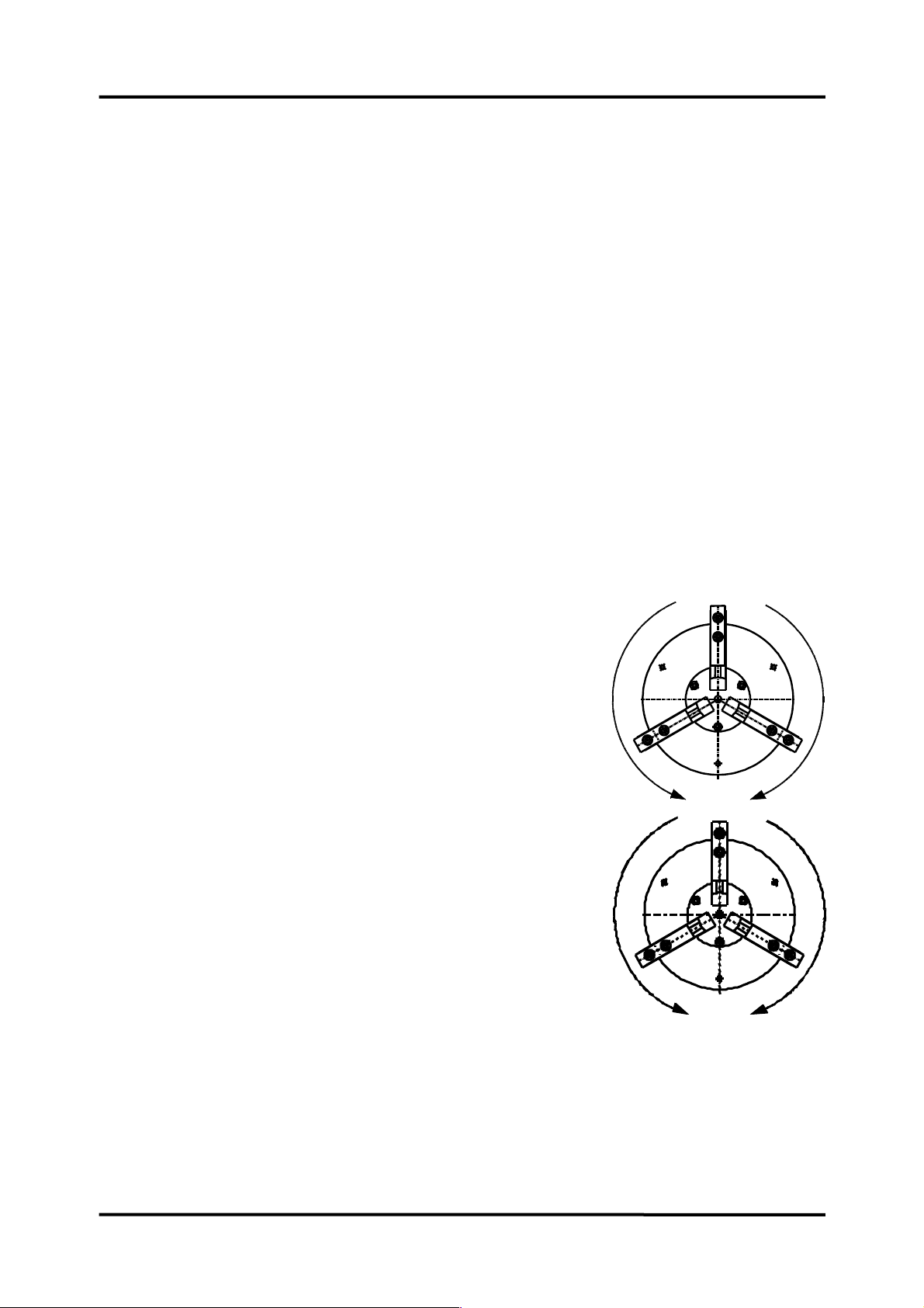
C-axis would be used to swivel the main spindle head in
order to position the work piece for drilling operations using a powered tool.
C+ is in clockwise direction and C- is counter clockwise direction.
A-axis would be used to swivel the sub-spindle head in
order to position the work piece for drilling operations using a powered
tool.
A+ is in clockwise direction and A- is counter clockwise direction.
Page 9

PROGRAMMING MANUAL -9-
Other axes that could be encountered when programming the machine are
F: feed axis (related to slides) to be programmed when in operation.
In millimetres x per revolution when the head is rotating (turning)
For example:
G99 F0.3 this means “03 millimetres per revolution”.
In millimetres per minute when the head is stopped (MC).
For example:
G98 F80 this means “80 millimetres per minute”
T: is turret rotation.
R: is radius programming.
S: are head revolutions (cutting speed) This letter is always related to heads.
G50 S1000 Rpm limit.
G97 S1000 fixed rpm (for tapping and drilling).
G96 S200 cutting speed (m/min) for all turning operations.
,C: Chamfer programming.
,A: Angle programming.
Tool offset
Cutting speed formula:
Dn
Vc=
1000
Vc1000
n=
D
Machines must be at the X home position for turret indexing.
Vc= Cutting speed
D= Part standard diameter
n= Rpm limit.
The required offset values must be entered each time tool position is changed with respect to the
aforementioned position; if tool position is not changed, entering a offset value will not be necessary
as these values are stored in the memory.
Entering tool offset values
There are two ways for entering tool correction values.
1st.) Supplied with presetter.
Page 10
PROGRAMMING MANUAL -10-
For machines with presetter, place the presetter in position and preset the tool.
2nd.) supplied without presetter.
For machines without presetter, turn the work piece and retract the tool without moving it out the
axis. Then measure the work piece and enter the readings in the geometry table.
To enter a value, go to the geometry table (offset value), enter the required value and press the
intermediate key; by this way the control unit will calculate the offset value.
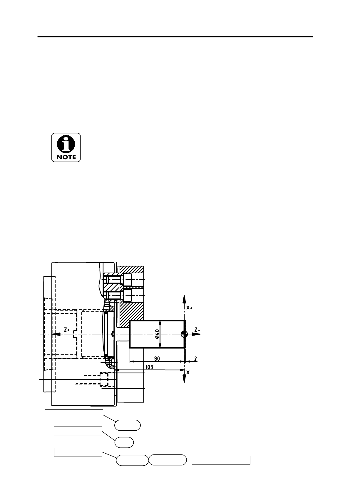
Workpiece zero reference point
Workpiece zero is the workpiece protruding length from main chuck face.
We advise you to enter workpiece zero at the beginning of the program.
Single spindle machine format
G10 P0 Z-80.
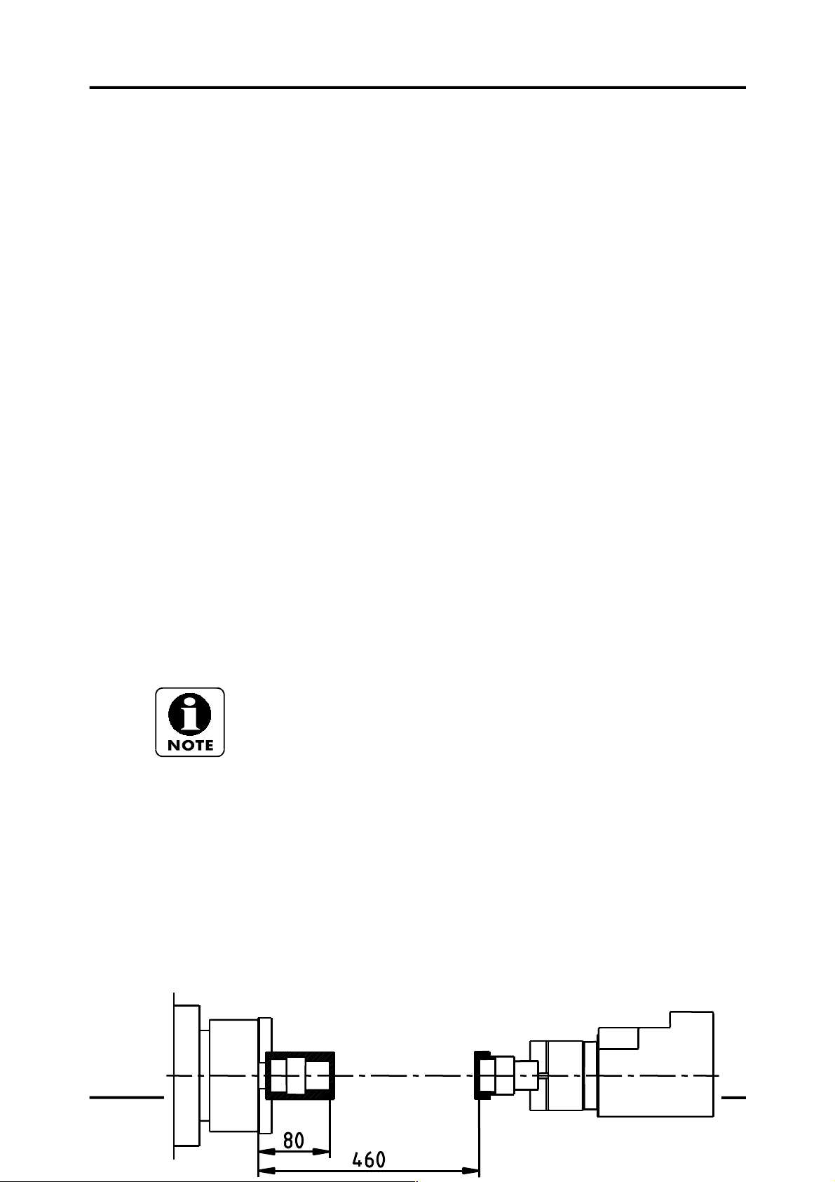
Sub spindle machine format
In the following example we explain how a value of 80 is entered for the first stage G54 (machining
the workpiece on the main spindle), while a value of 460 is entered for the second stage G55
(machining the workpiece on the sub-spindle).
G10 L2 P1 X0. Z-80. ;
G10 L2 P2 X0. Z-460. ;
Zero 1st phase
G10 L2 P1 Z-80
Zero 2nd phase
G10 L2 P2 Z-460
Page 11
PROGRAMMING MANUAL -11-
How to prepare the machine for machining operations with transfer:
1st Determine workpiece zero and carry out the 1st machining stage
G54 is programmed.
2nd Stop the machine and verify the dimension before doing the transfer.
3nd Do the transfer and place the sub-spindle in working position.
4nd Stop the machine and determine workpiece zero before performing the 2
machining stage G55 is programmed.
nd
Facing
Program number
O0001;
G21 ;
G10 L2 P1 X0. Z103 ;
M1;
N1 G28 U0. ;
T101
(FACING);
G50 S2000 (LIMIT R.P.M.);
G96 S200 M3;
G0 G40 G54 G99 X45 Y0. Z0 M8;
G1 X-2 F0.25;
G0 X150 Z100 M9;
M30;
Metric input
Data input
O0001;
G21;
Workpiece zero 103
Page 12
PROGRAMMING MANUAL -12-
G10 L2 P1 X0. Z103;
Line number
Comment
Spindle speed in
Rapid, Cancel tool
compensation and Feed
(mm/revolution)
Feed move
Rapid move to a safe
position
Program end rewind
to start of program
m/min
Move to X and Y
home position
N1 G28 U0.V0.
T101;
(FACING);
G50 S2000
G96 S200 M3;
Spindle rotation in
forward direction
G0 G40 G99 G54 X45. Z0. M8;
G1 X-2. F0.25;
G0 Z2. ;
X150. Z100. M9
M30;
Coolant off
Position the turret on
tool 1 with offset
number 01
Limit to
2000 r.p.m.
Coolant on
Selected work offset & Position tool
Feed rate per
revolution
End Point
In this manual we will always refer to G codes type A.
Comment::
These are notes included in the program.
These notes are totally optional, and it is up to the programmer to enter them or not.
These notes will be always placed in round brackets () in order to prevent the program reading
them.
T101
Here is shown that the tool to be used is in position 1 and a offset value of 01 is applied.
T0101 could be also entered, as the four mandatory characters are present, however, the first zero
is optional.
Head rotation direction:
M3 head rotation direction forward
M4 head rotation direction reverse
M5 spindle stop
If instructing the reverse from the forward direction or vice versa, the spindle must
be stopped first.
This is also valid for the sub spindle and live tools.
G0 X150 Z100
Note that tool retraction in this example is to 150 mm on X+ and 100 mm on Z+ from work piece
zero, and not from chuck face, as no order for changing the position is given to work piece zero,
which in this example is maintained in the previous position.
Line number (N10, N20...)
Page 13

PROGRAMMING MANUAL -13-
Line numbers are optional, and can be either entered or not.
G0 G40 G99 X45. Z0. M8
As you can see, G codes are first placed and then X, Z and M codes. Codes can be also entered in
the following manner: G0 X45. Z0.G99 G40 M8
Entering codes such as G96 and G50 in the same line is not permitted.
Page 14
PROGRAMMING MANUAL -14-
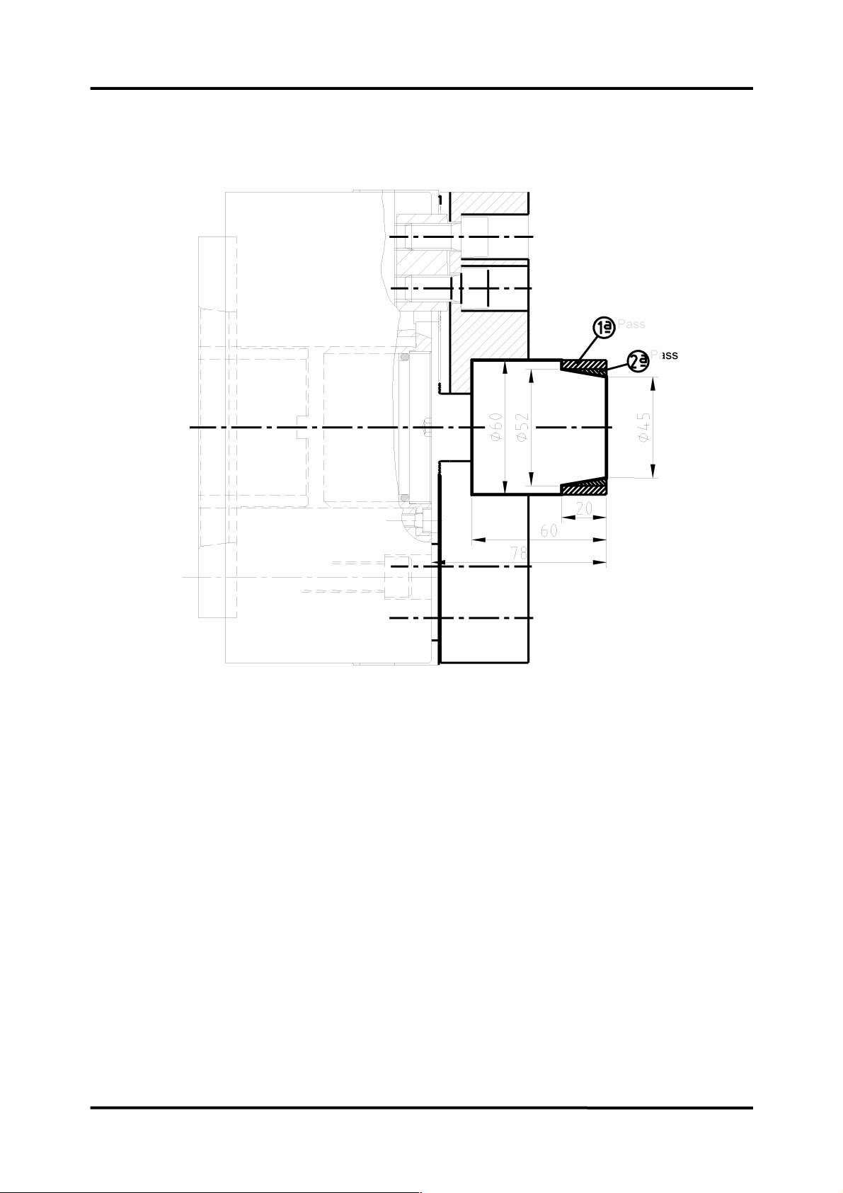
Taper turning
O0002; Name of the program
G21; Metric program
G10 L2 P1 X0. Z78; Part-zero at 78
N1 G28 U0.V0. Line number and move to X and Y home position
T101; Tool call (pos. 01 and offset 01)
(TURN); Description
G50 S1500; Spindle turning limit: 1500 rpm
G96 S200 M3; Cutting speed (m/min), Spindle fwd direction.
G0 G40 G54 G99 X52.5 Z2 M8; Rapid feed to point X52.5 Z2, Cancel tool nose radius
compensation, Feed per rev, Coolant on.
G1 Z-19.9 F0.25; Feed move Z-19.9 (First pass), Feed rate.
G0 X55 Z2; Rapid feed to X55 Z2
X45; Rapid feed to start point of cone in X45 Z2
G1 Z0; Feed move to X45 Z0
X52 Z-20 F.2; Machine the cone to X52 Z-20 (Second pass)
X61; Machine to X61 Z-20
G0 X150 Z100 M9; Rapid to safe position to 100mm in both axes and coolant
off
M30; End of program and back to he beginning
Page 15
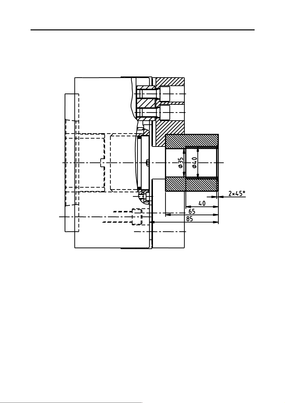
Inside turning:
PROGRAMMING MANUAL -15-
O0003;
G21; Metric input
G10 L2 P1 X0. Z85; Part zero at 85
N6 G28 U0.V0. Line number and move to X and Y home position
T606; Tool call (pos. 06 and offset 06)
(BORE); Description
G50 S2000; Turning speed limit: 2000 r.p.m.
G96 180 M3; Cutting speed =180 mm/rev, Spindle fwd direction.
G0 G40 G54 G99 X44 Z2 M8; Rapid move Z2 axis to the height of the chamfer 2x45º ,
Cancel tool nose radius compensation, Feed per rev,
Coolant on.
G1 Z0 F0.2; Feed move to Z0, feedrate 0.2 mm/rev
X40 Z-2 F.15; Machine chamfer with feedrate 0.15 mm/rev
Z-40 F.2; Machine the bore at ø40 with federate 0.2 mm/rev
X35; Face the inside until ø35
G0 Z5; Rapid feed to Z5
X150 Z100 M9; Rapid to safe position to X150 Z100 and coolant off
M30; End of program and back to he beginning
Page 16
PROGRAMMING MANUAL -16-
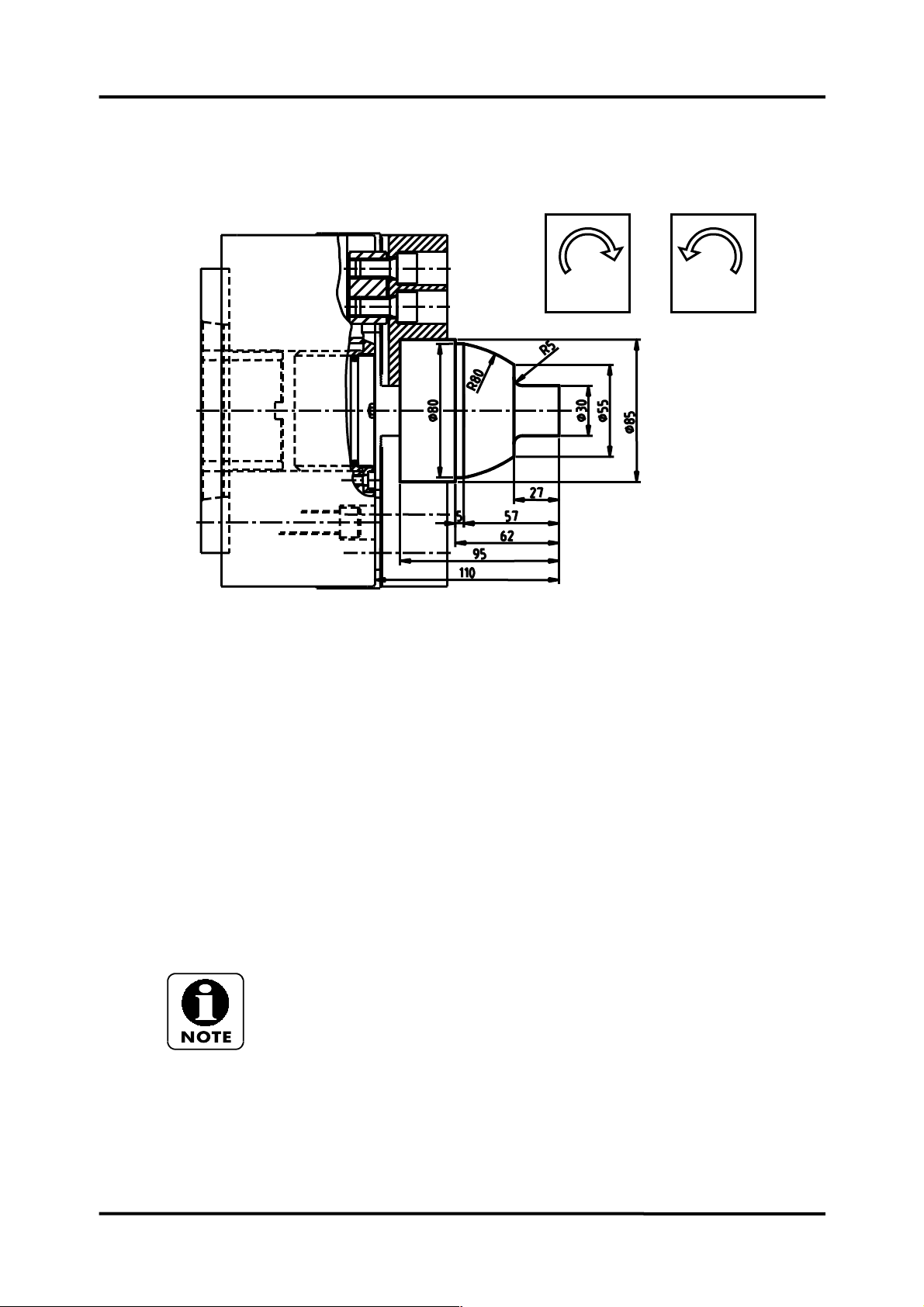
Circular Interpolation
G3G2
O0004;
G21; Metric input
G10 L2 P1 X0. Z110; Part zero at 110
N3 G28 U0.V0. Line number and move to X and Y home position
T303; Tool call (pos. 03 and offset 03)
(TURN); Description
G50 S2500;
G96 S220 M3;
G0 G40 G54 G99 X30 Z2 M8;
G1 Z-22 F0.2; Machine to ø30 and Z-22
G2 X40 Z-27 R5 (CLOCKWISE); 5mm radius clockwise to X40 Z-27
G1 X55; Face to X55
G3 X80 Z-57 R80 (COUNTERCLOCKWISE); 80mm radius counter clockwise to X80 Z-57
G1 Z-62; Machine to Z-60
X86; Face to X86
G0 X100 Z100 M9;
M30;
In this example we assume that the part is rough machined.
As seen in this example, G2 is used to machine radii in clockwise direction and G3 in
counterclockwise direction.
You can also see that G2 or G3 is first entered, then the end point, and finally the
radius,
Page 17
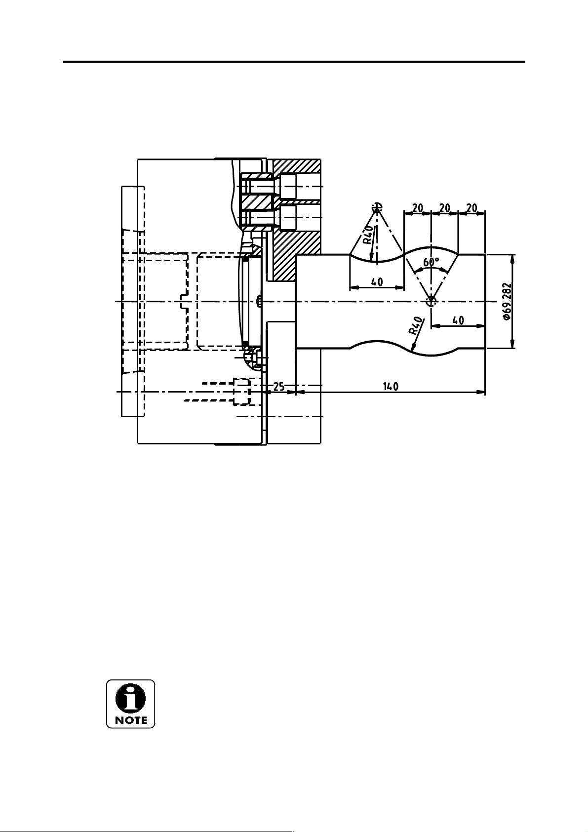
Circular interpolation
PROGRAMMING MANUAL -17-
O0005;
G21;
G10 L2 P1 X0. Z165;
N4 G28 U0.V0.
T404;
(TURN);
G50 S2000;
G96 S200 M3;
G0 G40 G54 G99 X69.282 Z2 M8; Rapid feed to X69.292 Z2
G1 Z-20 F0.2; Machining to Z-20
G3 X69.282 Z-60 R40; Machine a 40mm radius until point X69.282 Z-
60 counter clockwise direction
G2 X69.282 Z-100 R40; Machine a 40mm radius until point X69.282 Z-
100 clockwise direction
G1 Z-105; Machining to Z-105
G0 X150. Z100. M9;
M30;
As you can see, for the interpolation, you must know the point from which this
interpolation will take place in order to change radius direction (in this example on
point X69.282 Z-60).
Page 18
PROGRAMMING MANUAL -18-
Incremental commands (U and W)
O0006;
G21;
G10 L2 P1 X0. Z96:
N5 G28 U0.V0.
T505;
(GROOVE);
G97 S1250 M3;
G0 G40 G54 G99 X78 Z-20 M8; Rapid feed to X78 Z-20
G1 X65 F0.1; Grooving to ø65
G4 X1; Dwell (X1=1 second dwell )
G0 X78; Rapid feed to X78
W-10.; Incremental move –10mm in Z axis (W=Z)
G1 U-7.; Incremental move –7mm in X axis (U=X)
G4 X1; Dwell
G0 U7; Rapid feed 7mm in X axis (U=X)
W-15; Incremental move –15mm in Z axis (W=Z)
G1 U-9; Groove incrementally –9mm in X axis (ø69)
G4 X1; Dwell
G0 U9; Rapid feed incrementally 9mm in X axis (ø78)
X150 Z100 M9;
M30;
Time delays are entered each time a slot is machined in order to improve the
surface finish.
Page 19
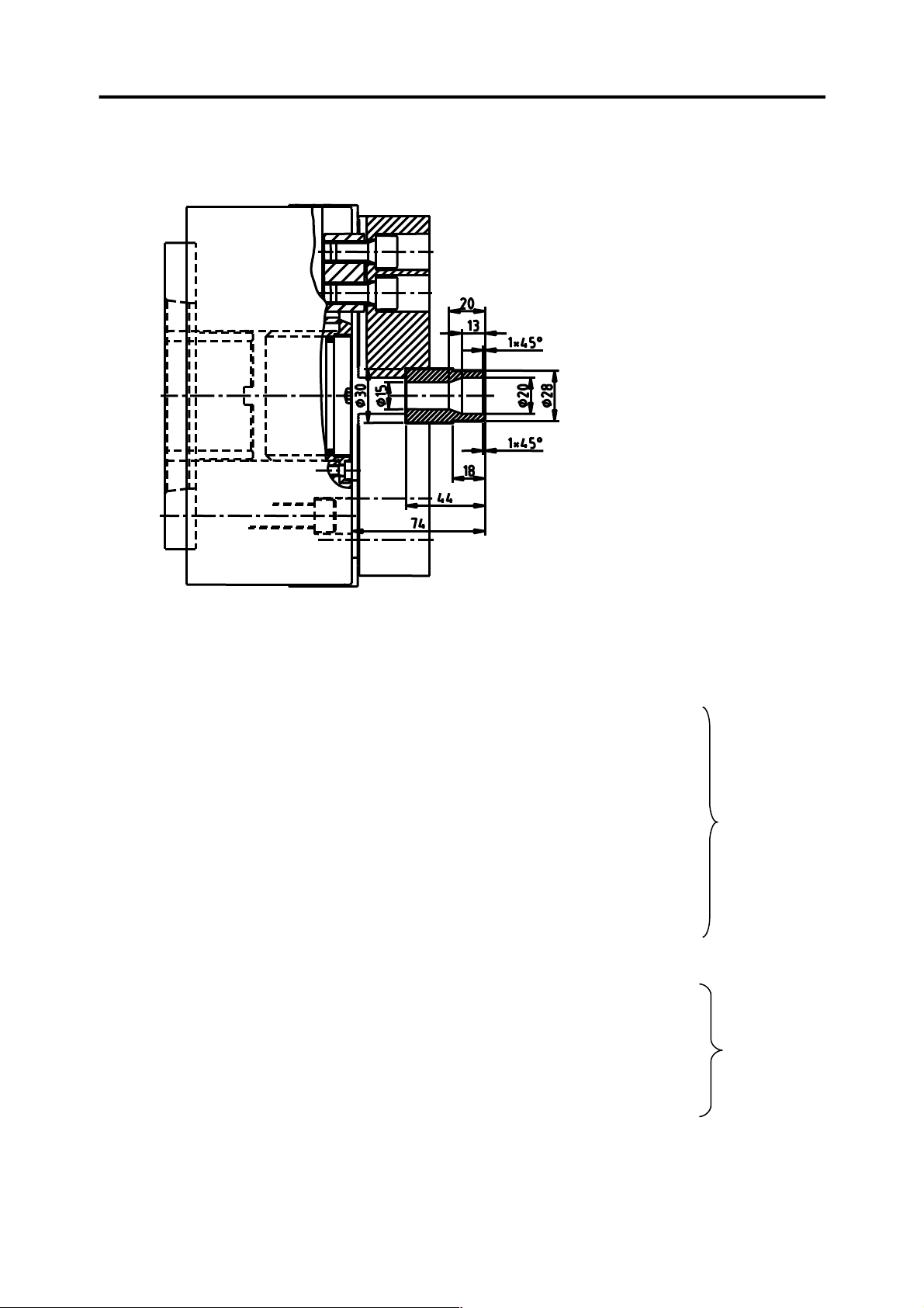
Example for operation
PROGRAMMING MANUAL -19-
Tools:
T1= Outside and facing.
T2= ø15 twist drill.
T4= Bore.
O0007;
G21;
G10 L2 P1 X0 Z74;
N1 G28 U0.V0.
T101;
(TURN);
G50 S2500;
G96 S220 M3;
G0 G40 G54 G99 X35 Z0 M8;
G1 X-2 F0.15;
G0 X26 Z2;
G1 Z0;
X28 Z-1 F0.2;
Z-18 F0.25;
X32;
G0 X150 Z100 M9;
M1;
N2 G28 U0.V0.
T202 ;
(15MM DIA DRILL);
G97 S600 M3;
G0 G40 G54 G99 X0 Z3 M8;
G1 Z-47 F0.1;
G0 Z10 M9;
X150. Z100.;
M1;
External machining
Drill
Page 20

PROGRAMMING MANUAL -20-
N4 G28 U0.V0.
T404;
(BORE);
G50S2250
G96 S150 M3;
G0 G40 G54 G99 X22 Z3 M8;
G1 Z0 F0.25;
X20 Z-1 F0.15;
Z-13 F0.2;
X15 Z-20 F0.15;
G0 Z5 M9;
X150 Z150;
M30;
Bore
Page 21

G Code List
For full explanation of the following G codes, refer to the examples in this manual or in the Fanuc
programming manual.
PROGRAMMING MANUAL -21-
STANDARD
G CODE
G00 01 RAPID TRAVERSE
G01 01 LINEAR INTERPOLATION
G02 01 CIRCULAR INTERPOLATION CLOCK WISE
G03 01 CIRCULAR INTERPOLATION COUNTERCLOCK WISE
G04 00 DWELL
G05 00 HIGH SPEED REMOTE BUFFER
G07.1 00 CYLINDRICAL INTERPOLATION
G10 00 PROGRAMMABLE DATA INPUT
G11 00 PROGRAMMABLE DATA INPUT CANCEL
G12.1 21 POLAR COORD INTERPOLATION MODE
G13.1 21 POLAR COORD INTERPOLATION MODE CANCEL
G17 16 XY PLANE SELECTION
G18 16 XZ PLANE SELECTION
G19 16 YZ PLANE SELECTION
G20 06 INCH INPUT
G21 06 MM INPUT
G22 09 STORED STROKE CHECK FUNCTION ON
G23 09 STORED STROKE CHECK FUNCTION OFF
G25 08 SPINDLE SPEED FLUCTUATION DETECTION OFF
G26 08 SPINDLE SPEED FLUCTUATION DETECTION ON
G27 00 REFERENCE POSITION RETURN CHECK
G28 00 REFERENCE POSITION RETURN
G30 00 2ND REFERENCE POSITION RETURN
G31 00 SKIP FUNCTION
G32 01 THREAD CUTTING
G34 01 VARIABLE LEAD THREAD CUTTING
G36 00 AUTOMATIC TOOL COMPENSATION X
G37 00 AUTOMATIC TOOL COMPENSATION Z
G40 00 TOOL NOSE RADIUS COMPENSATION CANCEL
G41 07 TOOL NOSE RADIUS COMPENSATION LEFT
G42 07 TOOL NOSE RADIUS COMPENSATION RIGHT
G50 07 MAXIMUM SPINDLE SPEED CLAMP
GROUP FUNCTION
Page 22

PROGRAMMING MANUAL -22-
STANDARD
G CODE
G52 00 LOCAL COORDINATE SYSTEM SETTING
G53 00 MACHINE COORDINATE SYSTEM SETTING
G54 14 WORKPIECE COORDINATE SYSTEM 1 SELECTION
G55 14 WORKPIECE COORDINATE SYSTEM 2 SELECTION
G56 14 WORKPIECE COORDINATE SYSTEM 3 SELECTION
G57 14 WORKPIECE COORDINATE SYSTEM 4 SELECTION
G58 14 WORKPIECE COORDINATE SYSTEM 5 SELECTION
G59 14 WORKPIECE COORDINATE SYSTEM 6 SELECTION
G65 06 MACRO CALL
G66 12 MACRO CALL MODAL
G67 12 MACRO CALL MODAL CANCEL
G70 00 FINISHING CYCLE
G71 00 STOCK REMOVAL IN TURNING
G72 00 STOCK REMOVAL IN FACING
G73 00 PATTERN REPEATING
G74 00 END FACE PECK DRILLING
G75 00 OUTER DIA DRILLING CYCLE/ GROOVING CYCLE
G76 00 MULTIPLE THREADING CYCLE
G80 10 CANNED CYCLE CANCEL
G83 10 CANNED CYCLE FOR FACE DRILLING
G84 10 CANNED CYCLE FOR FACE TAPPING
G85 10 CANNED CYCLE FOR FACE BORING
G87 10 CANNED CYCLE FOR SIDE DRILLING
G88 10 CANNED CYCLE FOR SIDE TAPPING
G89 10 CANNED CYCLE FOR SIDE BORING
G90 01 OUTER DIA/ INTERNAL DIA CUTTING CYCLE
G92 01 THREAD CUTTING CYCLE
G94 01 END FACE TURNING CYCLE
G96 02 CONSTANT SURFACE SPEED
G97 02 CONSTANT SURFACE SPEED CANCEL
G98 05 FEED PER MINUTE
G99 05 FEED PER REVOLUTION
GROUP FUNCTION
Page 23

PROGRAMMING MANUAL -23-
M FUNCTIONS
M functions used in machining programs are described in this section, this is a general list for the Kia range,
and some codes may not be active due to the machine specification.
Please refer to the individual manual supplied with the machine.
These codes control functions complementary to those controlled by G codes. For instance, coolant supply,
head rotation direction, etc.
M CODE FUNCTION NOTE
M00 PROGRAM STOP
M01 OPTIONAL STOP
M02 PROGRAM END
M03 SPINDLE FORWARD
M04 SPINDLE REVERSE
M05 SPINDLE STOP
M08 COOLANT ON
M09 COOLANT OFF
M10 BAR FEEDING ON OPTION
M11 BAR FEEDING OFF OPTION
M12 COUNTER OPTION
M13 MILL SPINDLE FORWARD
M14 MILL SPINDLE REVERSE
M15 MILL SPINDLE STOP
M18 SPINDLE ORIENTATION OFF OPTION
M19 SPINDLE ORIENTATION ON OPTION
M21 ERROR DETECT ON
M22 ERROR DETECT OFF
M23 CHAMFERING ON
M24 CHAMFERING OFF
M30 RESET AND REWIND OPTION
M31 COUNT UP CHECK OPTION
M36 AUTO POWER OFF ENABLE OPTION
M37 AUTO POWER OFF DISABLE OPTION
M38 CENTRE AIR BLOW ON OPTION
M39 CENTRE AIR BLOW OFF OPTION
M40 C-AXIS OFF OR LOW GEAR OPTION
M41 AUTO Q-SETTER ARM DOWN OPTION
M42 AUTO Q-SETTER ARM UP OPTION
M40 C-AXIS OFF OR LOW GEAR OPTION
M43 C-AXIS ON OR HIGH GEAR OPTION
M46 SPINDLE OVERRIDE ENABLE
M47 SPINDLE OVERRIDE DISABLE
M48 FEED OVERRIDE ENABLE
M49 FEED OVERRIDE DISABLE
M51 MAIN SPINDLE AIR BLOW ON OPTION
M52 MAIN SPINDLE AIR BLOW OFF OPTION
M54
M55
M61 AUTO DOOR OPEN OPTION
M62 AUTO DOOR CLOSE OPTION
CONSTANT SPINDLE SPEED CONTROL (MAIN
SPINDLE)
CONSTANT SPINDLE SPEED CONTROL (SUB
SPINDLE)
Page 24

PROGRAMMING MANUAL -24-
M63 PARTS CATCHER UP OPTION
M64 PARTS CATCHER DOWN OPTION
M66 LOW CHUCK PRESSURE OPTION
M67 HIGH CHUCK PRESSURE OPTION
M68 CHUCK CLOSE
M69 CHUCK OPEN
M70 CALL LIGHT ON
M73 SUB SPINDLE PARTS CATCHER UP
M74 SUB SPINDLE PARTS CATCHER DOWN
M75 CHIP CONVEYOR ON
M76 CHIP CONVEYOR OFF
M81 ROBOT SERVICE REQUEST 1 OPTION
M82 ROBOT SERVICE REQUEST 2 OPTION
M85 NEW BAR FEEDER LOADING OPTION
M90 C-AXIS BRAKE ON (HIGH)
M91 C-AXIS BRAKE OFF (LOW)
M98 SUB PROGRAM CALL
M99 END OF SUB PROGRAM
M108 SUB SPINDLE COOLANT ON
M109 SUB SPINDLE COOLANT OFF
M113 SUB SPINDLE FORWARD
M114 SUB SPINDLE REVERSE
M115 SUB SPINDLE STOP
M116 SUB SPINDLE ORIENTATION ON
M117 SUB SPINDLE ORIENTATION OFF
M118 SUB SPINDLE CHUCK CLAMP
M119 SUB SPINDLE CHUCK UNCLAMP
M114 SUB SPINDLE REVERSE
M115 SUB SPINDLE STOP
M116 SUB SPINDLE ORIENTATION ON
M117 SUB SPINDLE ORIENTATION OFF
M118 SUB SPINDLE CHUCK CLAMP
M119 SUB SPINDLE CHUCK UNCLAMP
M140 A-AXIS OFF
M141 EXTERNAL M CODE 1 OFF
M142 EXTERNAL M CODE 2 ON
M143 A-AXIS ON
M144 EXTERNAL M CODE 3 ON
M145 EXTERNAL M CODE 3 OFF
M146 EXTERNAL M CODE 4 ON
M147 EXTERNAL M CODE 4 OFF
M151 SUB SPINDLE AIR BLOW ON
M152 SUB SPINDLE AIR BLOW OFF
M160 S1, S2 SYNCHRONISATION ON
M161 S1, S2 SYNCHRONISATION OFF
M162 S1, S2 PHASE SYNCHRONISATION ON
Page 25
THREADING
PROGRAMMING MANUAL -25-
O0008;
G21;
G10 L2 P1 Z95;
N1 G28 U0.V0.
T101;
(TURN);
G50 S2500;
G96 S200 M3;
G0 G40 G54 G99 X70 Z0 M8;
G1 X-2 F0.25;
G0 X57 Z1;
G1 Z0;
X59.9 Z-1.5;
Z-45;
X66;
G0 X150 Z100 M9;
M1;
Page 26

PROGRAMMING MANUAL -26-
N2 G28 U0.V0.
T202;
(SCREWCUT);
G97 S700 M3;
G0 G40 G54 G99 X60 Z6 M8;
X59.4 (First pass);
G32 Z-40 F1 (F=THREAD PITCH);
G0 X62;
Z6;
X58.8 (Second pass);
G32 Z-40 F1;
G0 X62;
Z6;
X58.7 (Last pass);
G32 Z-40 F1;
G0 X62;
X150 Z100M9;
M30;
G32 for threading operations, always operate at fixed rpm (G97).
When retapping threads, do not release the work piece, do not change the speed
and do not change the start point.
Page 27
CANNED CYCLES
G70 Finishing cycle
G70 P100 Q200
P Block number from which the profile operation begins.
Q Block number from which the profile operation ends.
At the end of each cycle sequence the machine is always positioned in the position at
which this cycle sequence was started. The tool will be commonly located in the
position used for rough machining.
The profile allows changing X and Z direction.
G71 Longitudinal roughing cycle parallel to Z-axis
PROGRAMMING MANUAL -27-
G71 U3 R1
G71 P100 Q200 U0.3 W0.1 F0.25
U Cut depth on radius (mm).
R Retraction in radial direction from diameter to prevent touching the machined diameter (mm).
P Block number from which the profile operation begins.
Q Number of end block of profile.
U Finishing allowance for radius on X-axis (mm).
W Finishing allowance on Z-axis (mm).
F Instantaneous feed (mm/revolution).
At the end of each cycle sequence the machine is always positioned in the position at
which this cycle sequence was started.
The positioning allows changing X- and Z-axis direction.
Page 28
PROGRAMMING MANUAL -28-
G72 Cross roughing cycle transversal parallel to X-axis
G72 W3 R1
G72 P100 Q200 U0.25 W0.1 F0.3
W Depth of cut on Z-axis (mm).
R Retraction amount.
P Block number from which the profile operation begins.
Q Number of end block of profile.
U Finishing allowance for radius on X-axis (mm).
W Finishing allowance on Z-axis (mm).
F Instantaneous feed (mm/revolution).
Same as the above one, excepting for the profile.
G73 Roughing cycle with passes parallel to profile
G73 U9 W9 R3
G73 P100 Q200 U0.4 W0.1 F0.3
U Stock allowance (for radius) unmachined on X-axis (mm).
W Stock allowance on Z-axis (mm).
R Number of roughing passes.
P Block number from which the profile operation begins.
Q Number of end block of profile.
U Finishing allowance for radius on X-axis (mm).
W Finishing allowance on Z-axis (mm).
F Instantaneous feed (mm/revolution).
Page 29

G74 Drilling cycle (chip break)
G74 R0.5
G74 Z-100 Q2500 F0.25
R Retract distance (chip break).
Z Final drilling depth (absolute dimensions in mm).
Q Cut depth per pass (Microns).
F Feed rate (mm/revolution).
G83 Peck drilling cycle
G0 G80 G99 X0 Z3
G83 Z-60 Q2000 F0.2
G80
Z Final drilling depth (absolute dimensions in mm).
R Distance from the initial position to the start point (incremental value, not required if
already in position)
Q Depth of cut (Microns).
P Dwell time (s) at the bottom of the hole.
F Feed rate (mm/revolution).
PROGRAMMING MANUAL -29-
G84 Tapping cycle
Please note that if not using a LM or MS machine, then M122 and M123 can be omitted
G97 S500 M3
G0 G80 G99 X0 Z6
M122 (MAIN SPINDLE RIGID TAP ON)
M129S500 (RIGID TAP ON)
G84 Z-10 F1
G80
M128 (RIGID TAP OFF)
M123 (MAIN SPINDLE RIGID TAP OFF)
Z Final tapping depth (absolute dimensions in mm).
P Dwell time (s) at the bottom of the hole.
F Feed rate (mm/revolution).
G74 Front counter boring cycle
G74 R0.5
G74 X50 Z-4 P3000 Q4000 F0.15
R Retraction (mm) to break chips.
X (U) End position on X-axis (mm).
Z (W) End position in slot direction (mm).
P Step over on X-axis for next pass (Microns)
Q Cutting depth (Microns)
F Feed rate (mm/revolution).
Page 30

PROGRAMMING MANUAL -30-
G75 Longitudinal grooving cycle
G75 R0.2
G75 X43 W-7.5 P4000 Q2500 F0.15
R Retraction (mm) to break chips
X Groove bottom diameter (mm).
W Groove end point on Z-axis (mm) if Z is specified in absolute dimensions and W is the
displacement in incremental mode; from left-hand to right-hand (W+) and from right-hand to
left-hand (W-), always subtracting tool width.
P Cutting depth on X-axis (Microns).
Q Step over on Z-axis for next pass (Microns).
F Feed rate (mm/revolution).
IMPORTANT: Roughing cycles are without tool radius compensation. Because of
this, higher allowances will be specified for X and Z depending on tool radius.
G76 Threading cycle
G76 P030060 Q200 R0.05
G76 X98.773 Z-40 R0 P1227 Q400 F2
P03 Number of finishing passes.
P00 Thread run out ; distance at which thread outlet is started, in tenths of turn Example: If thread
pitch is 2 and 20 is entered: 2mm x 2 turns = 4 mm (thread runs out 4mm before the end point).
This is normally set to 00
P60 Thread angle in degrees
Q Minimum depth of cut (Microns).
R Finishing allowance (mm).
X Core diameter (mm).
Z Thread end point on Z-axis (absolute dimensions in mm).
R Height difference on radius (mm) for taper threads (Microns).
P Thread depth (Microns).
Q Cut depth for first pass (Microns).
F Thread pitch (mm).
Page 31

1. EXAMPLES OF CANNED CYCLES
G71 Canned roughing cycle
PROGRAMMING MANUAL -31-
O0071;
G21;
G10 L2 P1 X0. Z130;
N1 G28 U0.V0.
T101;
(ROUGH TURN);
G50 S2500;
G96 S200 M3;
G0 G40 G54 G99 X105 Z0 M8;
G1 X-2 F0.25;
G0 X105 Z1;
G71 U3 R1;
G71 P100 Q200 U2 W2 F0.3;
N100 G0 X40;
G1 Z-30;
X60 Z-60;
Z-80;
N200 X105 Z-90;
G70 P100 Q200 (FINISHING CYCLE)
G0 G40 X150 Z100 M9;
M30;
Page 32
PROGRAMMING MANUAL -32-
G74 and G83 fixed drilling cycles (with chip breakage)
G74 Drilling cycle with a short retraction for chip breakage
O0009;
G21;
G10 L2 P1 X0 Z75.;
N8 G28 U0.V0.
T808;
(DRILL);
G97 S265 M3;
G0 G40 G54 G99 X0 Z3. M8;
G74 R0.5;
G74 Z-60 Q20000 F0.2;
G0 X150 Z100 M9;
M30;
G83 Fixed drilling cycle with retraction at the start for chip breakage and removal
O0010;
G21;
G10 L2 P1 X0 Z75.;
N8 G28 U0.V0.
T808;
(DRILL);
G97 S500 M3;
G0 G40 G54 G99 X0 Z3 M8;
G83 Z-60 Q20000 F0.2;
G80
G0 X150 Z100 M9;
M30;
Page 33

G84 Rigid Tapping Cycle (Main spindle)
O0011;
G21;
G10 L2 P1 X0 Z-75.;
N8 G28 U0.V0.
T808;
(DRILL);
G97 S500 M3;
G0 G80 G54 G99 X0 Z3 M8;
M122
M129
G83 Z-60 Q20000 F0.2;
G80
M128
M123
G0 X150 Z100 M9;
M30;
PROGRAMMING MANUAL -33-
Page 34

PROGRAMMING MANUAL -34-
Page 35
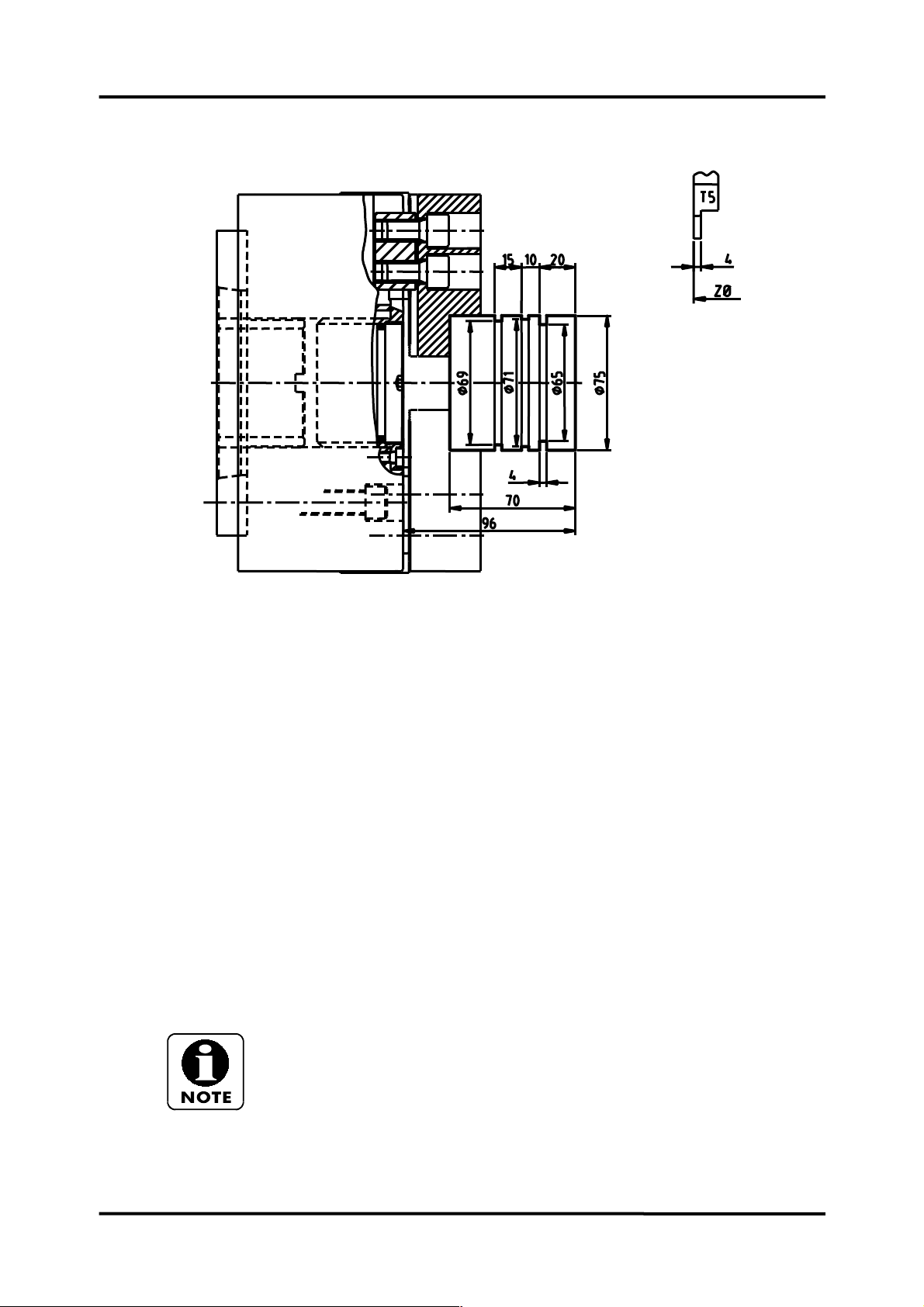
Fixed longitudinal grooving cycle
PROGRAMMING MANUAL -35-
O0011;
G21;
G10 L2 P1 X0 Z110.;
N7 G28 U0.V0.
T707;
(GROOVE);
G50 S1000;
G96 S110 M3;
G0 G40 G54 G99 X80 Z-55 M8;
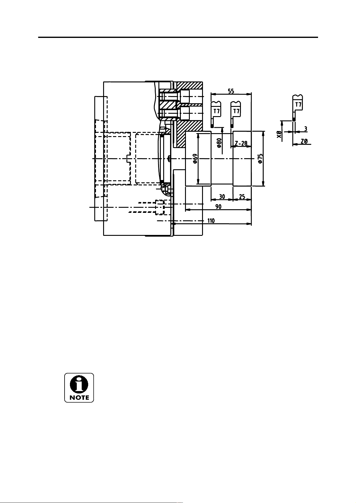
G75 R.5; Grooving with chip breaking
G75 X69 Z-28 P3000 Q2500 F.1; Grooving, penetrate until ø69 and until Z(W)-28,
penetration in X(P) 3mm, movement in Z(Q) 2.5mm.
G0 X150 Z100 M9;
M30;
Groove width or groove end point can be defined with a W code in this example
(W27, that is, 30 – 3 of tool), if tool is positioned on the right-hand would be (W-27).
For either Z or W, tool width must be subtracted.
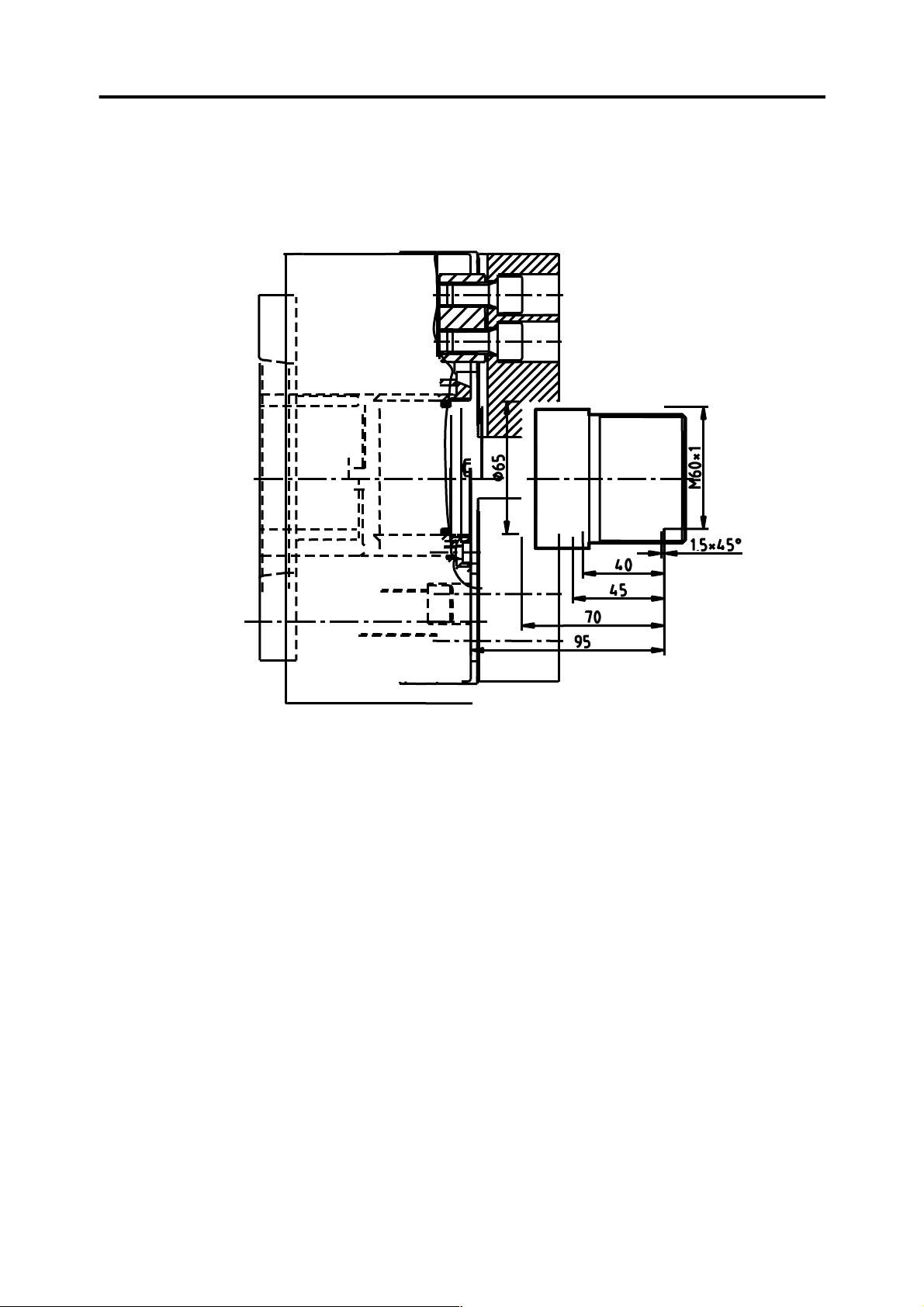
Threading fixed cycle
Page 36

PROGRAMMING MANUAL -36-
O0012;
G10 L2 P1 X0 Z88;
N1 G28 U0.V0.
T101;
(TURN);
G50 S2000;
G96 S200 M3;
G0 G40 G54 G99 X68 Z0. M8;
G1 X-2 F0.25;
G0 Z2;
G42 X54. Z1;
G1 X60 Z-2 F0.15;
Z-35 F0.25;
X66;
G0 G40 X150 Z100 M9;
M1;
N9 G28 U0.V0.
T909;
(SCREWCUT);
G97 S800 M3;
G4X1.
G0 G40 G54 G99 X62 Z6 M8;
G76 P030060 Q200 R0.03;
G76 X57.4 Z-30 P1227 Q400 F2;
G0 X150 Z100 M9;
M30;
Page 37
Application exercise for threading operations
PROGRAMMING MANUAL -37-
T1= OUTSIDE AND FACING.
T8= TWIST DRILL ø28
T10= BORING
T12= INTERNAL THREADING CUTTING
T5= EXTERNAL THREADING CUTTING
O0013;
G21;
G10 L2 P1 X0 Z100;
N1 G28 U0. V0.
T101;
(TURN)
G97 S200 M3
G0 G40 G54 G99 X73 Z0. M8;
G1 X-2 F0.2;
G0 X61 Z2;
G1 Z0;
X64.9 Z-2 F0.15 (THREAD DIAMETER);
Page 38

PROGRAMMING MANUAL -38-
Z-35 F0.2;
X70 Z-50 F0.15;
X71;
G0 X150 Z100 M9;
M1;
N8 G28 U0. V0.
T808
(DRILL)
G97 S300 M3
G0 G54 G99 X0 Z3 M8;
G74 R1;
G74 Z-84 Q3000 F0.15;
G0 X150 Z100 M9;
M1
N10 G28 U0. V0.
T1010
(BORE)
G97 S150 M3;
G0 G40 G54 G99 X34 Z2 M8;
G1 Z0 F0.25;
X29.6 Z-2 F0.15;
Z-30 F0.2;
X27;
G0 X150 Z100 M9;
M1;
N12 G28 U0. V0.
T1212
(INTERNAL SCREWCUT)
G97 S1275 M3;
G4X2.;
G0 G54 G99 X28 Z6;
G76 P030060 Q300 R0.05;
G76 X32 Z-25 P1230 Q450 F2;
G0 X150 Z100 M9;
M1;
N5 G28 U0. V0.
T505;
(EXTERNAL SCREWCUT)
G97 S650 M3;
G4 X2.;
G0 G54 G99 X67 Z6.;
G76 P030060 Q300 R0.05;
G76 X63.05 Z-30 P920 Q400 F1.5;
G0 X130 Z25 M9;
M30;
Page 39
PROGRAMMING SIMPLIFICATION FUNCTIONS
PROGRAMMING MANUAL -39-
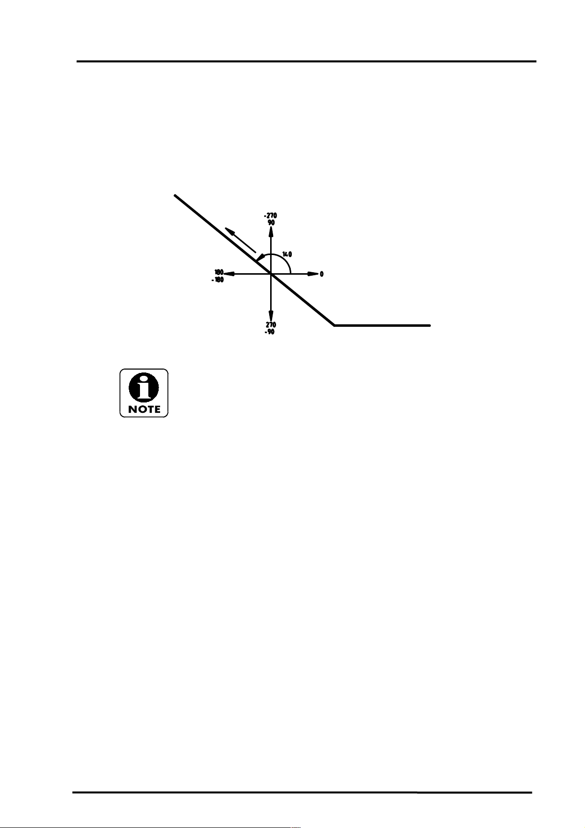
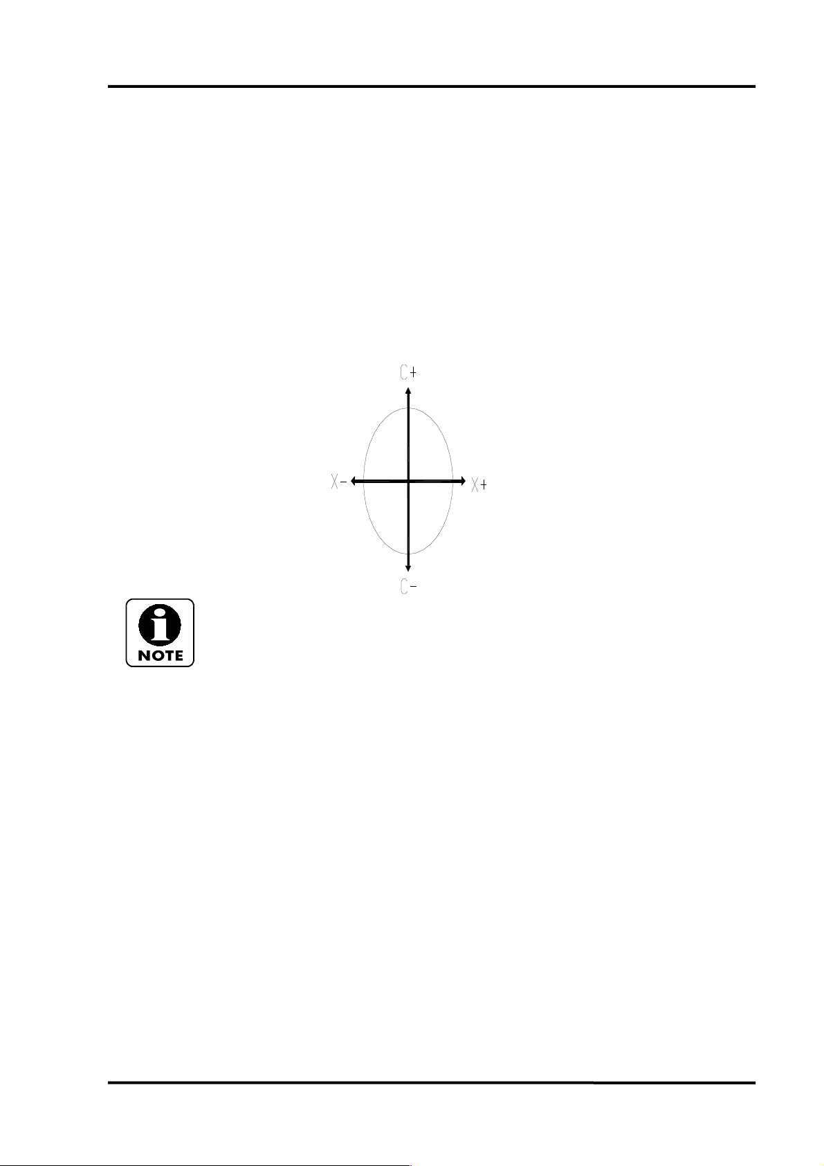
In theses cases, considering tool direction is most important.
The easier procedure is drawing a quadrant on the drawing and locate the
degrees as shown on the above diagram.
Page 40
PROGRAMMING MANUAL -40-
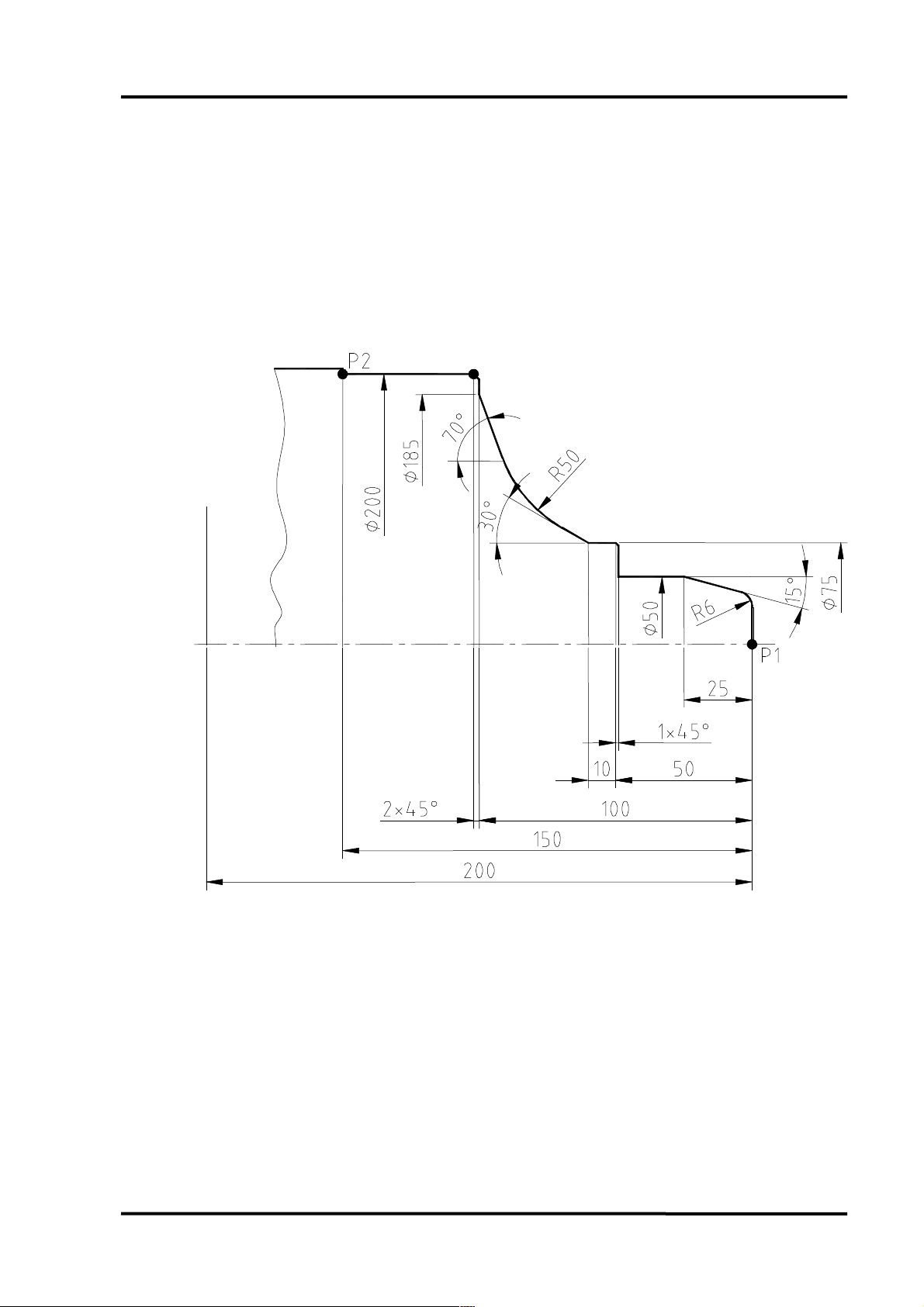
Direct programming of profile (angles and round edges)
Page 41

PROGRAMMING MANUAL -41-
O0014;
G21;
G10 L2 P1 X0 Z120;
N3 G28 U0.V0.
T303;
G50 S2200;
G96 S230 M3;
G0 G54 G40 G99 X0 Z3. M8;
G1 Z0 F0.15 (P1);
,A90 ,R6 (FIRST ANGLE);
,A165 X50 Z-25 (SECOND ANGLE); A165 comes from 180°-15°=165°
,A180 Z-49.;
,A90 X75. ,C1;
Z-60;
,A150 ,R50; A150 comes from 180°-30°=150°
,A110 X185 Z-100; A110 comes from 180°-70°=110°
,A90 X200 ,C2;
,A180 Z-150. (P2);
G0 X250 Z100 M9;
M30;
Page 42

PROGRAMMING MANUAL -42-
Tool radius compensation
1st) Type of tool (Control) T (Offsets table).
2st) Radius inserts of tool (Control) R (Offsets table).
3st) Workpiece position with respect to tool (Part program) G41 or G42.
<EXTERNAL>
<INTERNAL>
Page 43

Tool types
PROGRAMMING MANUAL -43-
Milling cutters are assigned with type “0” or “9” for interpolations.
Page 44

PROGRAMMING MANUAL -44-
G40 G41 and G42 tool radius compensation
Tools
T1 = EXTERNAL
T8= TWIST DRILL ø38
T10 = INTERNAL
Page 45

O0015 (TOOL RADIUS COMPENSATION G40, G41, G42);
G21;
G10 L2 P1 X0 Z-95.;
N1 G28 U0.V0.
T101;
(TURN);
G50 S2200;
G96 S200 M3;
G0 G40 G54 G99 X110 Z0 M8;
G1 X-2 F0.25;
G0 X100 Z2;
G1 Z-17;
G0 X102 Z3;
G42 X95 Z1 (ACTIVES COMPENSATION RIGHT);
G1 Z0 F0.1;
X97 Z-1 F0.15;
Z-15 F0.2;
,A150 X102.;
,A180 Z-45;
X106.;
G0 G40 X150 Z100 M9 (CANCEL TOOL COMPENSATION);
M1 ;
PROGRAMMING MANUAL -45-
N8 G28 U0.V0.
T808 ;
(DRILL 38MM DIA);
G97 S165 M3;
G0 G54 G99 X0 Z3 M8;
G74 R1;
G74 Z-80 Q25000 F0.25;
G0 X150 Z100 M9;
M1;
N10 G28 U0.V0.
T1010
(BORE);
G50 S2000
G96 S150 M3;
G0 G40 G54 G99 X45 Z2 M8;
G1 Z-6 F0.2;
X41 Z-35;
Z-38.9;
G0 X37 Z2;
G41 X50 Z1 (ACTIVES COMPENSATION LEFT);
G1 X46 Z-1 F0.15;
Z-6;
X42 Z-35;
Z-39;
X37;
G40 X35(CANCEL TOOL COMPENSATION);
G0 Z10. M9 ;
X150 Z100 ;
M30;
Page 46

PROGRAMMING MANUAL -46-
G71 Type I - Example of roughing and finishing cycle with direct definition of profile and tool radius compensation
Page 47

O0016 (Example of roughing cycle G71 Type I);
G21;
G10 L2 P1 X0 Z115.;
N1 G28 U0.V0.
T101
(ROUGH TURN);
G50 S2500;
G96 S200 M3;
G0 G40 G54 G99 X115 Z2 M8;
G1 X-2 F0.25;
G0 Z2. ;(POSITIONING, STARTOF CYCLE);
X111;(POSITIONING, STARTOF CYCLE);
G71 U3 R1 (ROUGHING CYCLE);
G71 P100 Q200 U0.3 W0.1 F0.25;
N100 G0 X52 (START OF PROFILE);
G42 X54. Z1.
G1 X60. Z-2 F0.15;
Z-22;
,A170. ,R20;
,A140. X95 Z-50. ,R5.;
,A180.;
,A135. X110 Z-64;
N200 G40 X111 (END POINT OF PROFILE);
G0 X150 Z100 M9;
M1;
PROGRAMMING MANUAL -47-
N3 G28 U0.V0.
T303
(FINISH TURN);
G50 S2500;
G96 S230 M3;
G0 G40 G54 G99 X62 Z0 M8;
G1 X-1 F0.15;
G0 Z2;
X111. (POSITIONING START OF CYCLE);
G70 P100 Q200 (FINISHING CYCLE);
G0 X150 Z100 M9;
M1;
N5 G28 U0.V0.
T505;
(SCREWCUT);
G97 S750 M3;
G4X1.;
G0 G54 G99 X62 Z6 M8;
G76 P030055 Q050 R0.05;
G76 X57.641 Z-19. P1179 Q450 F1.814;
G0 X150 Z100 M9;
M30;
All cycles end where they are started and, because of this, finishing positioning is
done above the workpiece.
Page 48
PROGRAMMING MANUAL -48-
G71 Type II - Roughing cycle with displacement direction reversal on X-axis
Page 49

O0017 (Example of roughing cycle G71 Type II)
G21;
G10 L2 P1 X0 Z115;
N1 G28 U0.V0.
TI01;
(ROUGH TURN);
G50 S2250;
G96 S200 M3;
G0 G40 G54 G99 X95 Z0.1 M8;
G1 X-2 F0.2;
G0 Z2.;
X92;
G71 U2.5 R1;
G71 P100 Q200 U1.2 W0.1 F0.2;
N100 G0 X60 Z1.;
G1 G42 Z0 F0.15;
G3 X76 Z-39 R40;
G1 Z-57;
X90 Z-65;
N200 G0 G40 X92;
X150 Z100 M9;
M1;
PROGRAMMING MANUAL -49-
N3 G28 U0.V0.
T303;
(FINISH TURN);
G50 S2750;
G96 S220 M3;
G0 G40 G54 G99 X65 Z0 M8;
G1 X-2 F0.15;
G0 Z2.;
X92;
G70 P100 Q200;
X150 Z100 M9;
M30;
For control units with capability for machining profiles with X-axis direction
reversal, the first block for defining the profile must state the movement of the two
axes.
Page 50
PROGRAMMING MANUAL -50-
G72 Example of cross roughing cycle parallel to X-axis
TOOLS:
T1 = EXTERNAL ROUGHING
T2 = EXTERNAL FINISHING
T6 = INTERNAL ROUGHING
T10 = INTERNAL FINISHING
Page 51

ROUGHING CYCLE APPLICATION
00018 (Example of roughing cycle G72);
G21;
G10 L2 P1 X0 Z115.;
N1 G28 U0.V0.
T101;
(ROUGH TURN);
G50 S2200;
G96 S200 M3;
G0 G40 G54 G99 X95 Z0.1 M8;
G1 X18 F0.25;
G0 X92 Z2;
G72 W2.5 R1;
G72 P100 Q200 U0.3 W0.15 F0.25;
N100 G0 G41 Z-15;
G1 X90;
X88 Z-1;4;
X55 ,R4;
Z-1.5;
N200 X50. Z1;
G0 X150 Z100 M9;
M1;
PROGRAMMING MANUAL -51-
N6 G28 U0.V0.
T606;
(ROUGH BORE);
G50 S2250;
G96 S150 M3;
G0 G40 G54 G99 X18 Z2 M8;
G71 U2.5 R1;
G71 P300 Q400 U-0.3 W0.1 F0.2;
N300 G0 X45;
G41 X43. Z1;
G1 X38 Z-1.5 F0.1;
,A180 ,R15;
,A195. X25 Z-30;
X22;
X20 Z-31;
N400 G40 X18.
G0 X150 Z100 M9;
M1;
N10 G28 U0.V0.
T1010;
(FINISH BORE);
G50 S1750;
G96 S180 M3;
G0 G40 G54 G99 X18 Z2 M8;
G70 P300 Q400;
G0 X150 Z100 M9;
M1;
Page 52

PROGRAMMING MANUAL -52-
N3 G28 U0.V0.
T303;
(FINISH TURN);
G50 S2250;
G96 S230 M3;
G0 G40 G54 G99 X57 Z0 M8;
G1 X35. F0.1;
G0 X92 Z2;
G70 P100 Q200
G0 G40 X150 Z100 M9;
M30;
Page 53

M98 Repetitions of a subprogram
PROGRAMMING MANUAL -53-
SUBPROGRAM REPETITION APPLICATION
00019 (Repeating of subprogram M98);
G21;
G10 L2 P1 Z150.;
N5 G28 U0.V0.
T505;
(GROOVING);
G50 S1750;
G96 S100 M3;
G0 G40 G54 G99 X74 Z-59 M8;
M98 P1000 (CALLING TO SUBPROGRAM 01000);
G0 Z-42;
Page 54

PROGRAMMING MANUAL -54-
SUBPROGRAM FOR A SLOT:
M98 P1000;
G0 Z-25;
X44;
M98 P1000;
G0 Z-10;
M98 P1000;
G0 X200 Z200 M9;
M30;
01000 (SUBPROGRAM FOR THE SLOT);
G1 U-12 F0.1;
G4 X1;
G0 U12;
W-1;
G1 U-4;
U-2 W1;
G0 U6;
W1;
G1 U-4;
U-2 W-1;
G0 U6;
M99 (END OF SUBPROGRAM);
The subprogram is called by means of command P followed by a number. This
number consists of four or more characters.
If the number consists of four characters, it indicates the identification number of
subprogram to be called.
If the number consists of more than four characters, the first four characters, from
right to left, indicate the identification number of subprogram to be called. Next
characters indicate the number of repetitions of subprogram to be called.
Page 55
M98 Repetition of parts of a program
PROGRAMMING MANUAL -55-
Page 56

PROGRAMMING MANUAL -56-
PARTS OF A PROGRAM REPETITION APPLICATION:
00020 (REPEATING OF PARTS OF A PROGRAM);
G21;
G10 L2 P1 Z150.;
N4 G28 U0.V0.
T404;
(GROOVING);
G50S1750;
G96 S90 M3;
G0 G40 G54 G99 X46 Z0 M8;
M98 P21001 (REPEATS TWO TIMES 1001);
G0 X200 Z200 M9;
M30;
SUBPROGRAM FOR A SLOT:
O1001 (SUBPROGRAM FOR GROOVING);
W-10;
G1 X30 F0.1;
G4 X1;
G0 X36;
M99;
As described above, a subprogram or part of a subprogram is repeatedly called by means of a
command P followed by several numerical characters. In this example, the subprogram is
repeatedly called by means of “P21001”.
This command consists of three parts:
“P” calling a subprogram.
“2” number of subprogram repetitions.
“1001” number consisting of four characters and directly referring to the subprogram.
The maximum number of repetitions for a subprogram in a single call is
9999.
Page 57
PROGRAMMING MANUAL -57-
OTHER EXAMPLE OF SUBPROGRAM EXECUTION REPETITION
PROGRAM:
O0021 (EXAMPLE OF M98);
G21
G10 L2 P1 Z130;
M98 P30002 (REPEATS 3 TIMES THE SUBPROGRAM 0002);
G0 X150 Z150 M9;
M30;
SUBPROGRAM
00002 (SUBPROGRAM);
N1 G28 U0.V0.
T101;
G50 S1500;
G96 S150 M3;
G0 G40 G54 G99 X30 Z-10;
G1 X-2 F0.08;
G0 X30;
G10 P0 W10;
M99
Page 58

PROGRAMMING MANUAL -58-
Bar feed examples (Hydrafeed)
O5000 (BAR FEED DEMO)
G21
G10 L2 P1 X0. Z165.
N12 G28 U0.V0.
T1212
(STOP)
#110=50(COMPONENT LENGTH)
M98 P8888
M1
O8888(BAR FEED)
(#110=COMPONENT LENGTH AS POSITIVE)
G28U0.V0.
M5
G0G40G98M9M10(PUSH)
Z50.
X0.
/2 M98 P8889
G1Z-#110F2500.
M69 (CHUCK OPEN)
G4X2.
Z0.5 F3500.
M68 (CHUCK CLOSE)
M11 (STOP PUSH)
G04 X2.
G0 Z50.
G28U0.V0.
M99
O8889 (LOAD NEW BAR)
G0 Z50.
G28 U0. V0.
M63 (PARTS CATCHER UP)
M69 (CHUCK OPEN)
M85 (EJECT)
G4 X1.
M64 (PARTS CATCHER DOWN)
G4 X1.
G0 X0.
G1G98Z-#110F2500.
M85 (NEWBAR)
M68 (CHUCK CLOSE)
G99
M99
Page 59

A+
A-
C+
C-
C-Axis, A axis and powered tooling
This section describes the procedures used to program SY type machines controlled by the Cand A-axis.
1- Stop the spindle (S1 and/or S2) by entering the command M5 (S1) or M115
(S2) before entering M43 or M143 command.
2- After activating M43 C-axis on G28 C0. must be entered .
3- After activating M143 A-axis on G28 A0. must be entered.
4- Before entering command M40 and M140, the powered tool must be stopped
by entering command M15.
PROGRAMMING MANUAL -59-
C or A -axis would be used to swivel the head in order to
position the work piece for drilling operations using a
powered tool.
C or A + is in clockwise direction and C or A- is counter
clockwise direction.
Page 60

PROGRAMMING MANUAL -60-
M codes related to C and A-axis functions
M13 Mill spindle forward direction
M14 Mill spindle reverse direction
M15 Mill spindle stop
M40 C-Axis disconnect
M43 C-Axis connect
M90 C-axis brake on (high pressure set to 24 bar)
M91 C-axis brake off (low pressure set to 6 bar)
M140 A-Axis disconnect
M143 A-Axis connect
G83 Front drilling cycle (powered tool)
(chip breakage with retraction to the start point)
G0 G80 G98 X30 Z3
G83 Z-30 H90 K4 Q2000 M90 F100
G80
X hole position
C hole position (not required if already in position)
Z Final drilling depth (absolute dimensions in mm)
R Distance from the initial position to the start point (incremental value, not required if
already in position)
H distance between two holes in degrees.
K number of holes.
Q Depth of cut (microns).
P Dwell time (s) at the bottom of the hole.
F Feed rate (mm/min).
M90 brake on (the brake will automatically unclamp before indexing within the cycle).
Page 61

PROGRAMMING MANUAL -61-
G184 Front rigid tapping cycle (Z-axis direction powered tool)
G0 G80 G98 X30 Z6
G184 C30 R-2 D.5 W20 Q1 F500
G184 C150 R-2 D.5 W20 Q1 F500
G184 C270 R-2 D.5 W20 Q1 F500
C C-axis angle.
R Return point.
D Dwell at bottom of hole.
WDistance from R point to the bottom of the hole.
Q Pitch of tap.
F Cutting feed.(Rpm x Pitch).
(Must use decimal point)
(M90 and M91 are automatically commanded in the macro).
G87 Side drilling cycle (powered tool)
(chip breakage with retraction to the start point)
G0 G80 G98 X50 Z-20
G83 X30 H90 K4 Q2000 M90 F100
G80
X Final drilling depth (absolute dimensions in mm)
C hole position (not required if already in position)
Z hole position
R Distance from the initial position to the start point (incremental value, not
required if already in position)
H distance between two holes in degrees.
K number of holes.
Q Depth of cut (microns).
P Dwell time (s) at the bottom of the hole.
F Feed rate (mm/min).
M90 brake on (the brake will automatically unclamp before indexing within the
cycle).
Page 62

PROGRAMMING MANUAL -62-
G188 Side rigid tapping cycle (X-axis direction powered tool)
G0 G80 G98 X50 Z6
G188 C30 R-2 D.5 U20 Q1 F500
G188 C150 R-2 D.5 U20 Q1 F500
G188 C270 R-2 D.5 U20 Q1 F500
(M90 and M91 are automatically commanded in the macro).
C C-axis angle.
R Return point.
D Dwell at bottom of hole.
UDistance from R point to the bottom of the hole.
Q Pitch of tap.
F Cutting feed.(Rpm x Pitch).
(Must use decimal point)
G185 Back rigid tapping cycle (Z-Axis Direction powered tool Sub Spindle)
G0 G80 G98 X50 Z-6
G185 A30 R2 D.5 U20 Q1 F500
G185 A150 R2 D.5 U20 Q1 F500
G185 A270 R2 D.5 U20 Q1 F500
A A-axis angle.
R Return point.
D Dwell at bottom of hole.
UDistance from R point to the bottom of the hole.
Q Pitch of tap.
F Cutting feed.(Rpm x Pitch).
(Must use decimal point)
(M90 and M91 are automatically commanded in the macro).
Page 63

PROGRAMMING MANUAL -63-
G83 Example of face front drilling cycle with powered tool (Main Spindle)
O0019
G21;
G10 L2 P1 X0 Z100;
N6 G28 U0. V0.
T606
(AXIAL 6MM DIA DRILL)
M5
M43
G28 H0
G97 S2500 M13
G0 G54 G80 G98 X90.Z2M8
G83 Z-10.K4 H90.M90 F100.
G80
M15
M40
G0 X150 Z150 M9
M1
ALTERNATIVE PROGRAM
This fixed drilling cycle can be programmed in the apparently more logic and simple sequence, ie,
0º - 90º - 180º - 270º. This cycle would be as follows:
O0020
G21;
G10 L2 P1 X0 Z100;
N6 G28 U0. V0.
T606
(AXIAL 6MM DIA DRILL)
M5
M43
G28 H0
G97 S2500 M13
G0 G54 G80 G98 X90.Z2M8
G83 Z-10. Q2000 M90 F100.
C90. Q2000 M90
C180. Q2000 M90
C270. Q2000 M90
G80
M15
M40
G0 X150 Z150 M9
M1
Page 64
PROGRAMMING MANUAL -64-
G83 Example of face front drilling cycle with powered tool (Sub Spindle)
O0019
G21;
G10 L2 P2 X0 Z100;
N6 G28 U0. V0.
T606
(AXIAL 6MM DIA DRILL)
M5
M143
G28 A0.
G97 S2500 M13
G0 G55 G80 G98 X90.Z-2.M8
G83 A0. Z10. Q2000 M90 F100.
A90. Q2000 M90
A180. Q2000 M90
A270. Q2000 M90
G80
M15
M140
G0 X150 Z150 M9
M1
Page 65
PROGRAMMING MANUAL -65-
G87 Example program of a side radial drilling cycle with powered tool(Main Spindle).
3 HOLES SPACED 120º
O0021
G21;
G10 L2 P1 X0 Z100;
N8 G28 U0.
T808
(RADIAL 4MM DIA DRILL)
M5
M43
G28 H0
G97 S3500 M13
G0 G54 G80 G98 X122.Z-15.
G87 X96.Q3000 M90 F350.
C120.Q1000 M90
C240.Q1000 M90
G80
M15
M40
G0 X150.Z150.M9
M1
Page 66
PROGRAMMING MANUAL -66-
G87 Example program of a side radial drilling cycle with powered tool(Main Spindle using Y-axis).
O0221
G21;
G10 L2 P1 X0 Z100;
N8 G28 U0.
T808
(RADIAL 4MM DIA DRILL)
M5
M43
G28 H0
G97 S3500 M13
G0 G54 G80 G98 X122.Z-10.
G87 X96. Y-10. C0. Q3000 M90 F350.
Z-20. Y-10. Q1000 M90
Z-20. Y10. Q1000 M90
Z-10. Y10. Q1000 M90
G80
M15
M40
G0 X150.Z150.M9
M1
Page 67
PROGRAMMING MANUAL -67-
G87 Example program of a side radial drilling cycle with powered tool(Sub Spindle).
3 HOLES SPACED 120º
O0021
G21;
G10 L2 P1 X0 Z100;
N8 G28 U0.
T808
(RADIAL 4MM DIA DRILL)
M5
M143
G28 A0.
G97 S3500 M13
G0 G55 G80 G98 X122.Z15.
G87 X96.Q3000 M90 F350.
A120.Q1000 M90
A240.Q1000 M90
G80
M15
M140
G0 X150.Z150.M9
M1
Page 68
PROGRAMMING MANUAL -68-
G184 Example program of a front face tapping cycle with powered tool (Main spindle )
O0184 (FRONT TAP)
G28 U0 V0
T1010
M5
M43
G28 H0
G0 G54 G80 G98 X90 Z6
G184 C0 R2 W14 Q1 F800
G184 C90 R2 W14 Q1 F800
G184 C180 R2 W14 Q1 F800
G184 C270 R2 W14 Q1 F800
M15
M40
G0 Z100
G28 U0 V0
M30
Page 69
PROGRAMMING MANUAL -69-
G185 Example program of a back face tapping cycle with powered tool (Sub spindle)
O0185(SUB TAP)
G28 U0 V0
T0404
M5
M143
G28 A0
G30 B0
G0 G55 G80 G98 X90 Z-6
G185 A0 R2 W14 Q1 F800
G185 A90 R2 W14 Q1 F800
G185 A180 R2 W14 Q1 F800
G185 A270 R2 W14 Q1 F800
M15
M140
G0 Z-100
G28 U0 V0
M30
Page 70
PROGRAMMING MANUAL -70-
G188 Example program of side tapping cycle with powered tool (Main spindle)
O0188 (SIDE TAP)
G28 U0 V0
T1212
M5
M43
G28 H0
G0 G54 G80 G98 X90 Z-10
G188 C0 R2 U14 Q1 F800
G188 C90 R2 U14 Q1 F800
G188 C180 R2 U14 Q1 F800
G188 C270 R2 U14 Q1 F800
M15
M40
G0 Z100
G28 U0 V0
M30
Page 71

PROGRAMMING MANUAL -71-
G188 Example program of side tapping cycle with powered tool (Main spindle using Y Axis).
O0189 (SIDE TAP Y MAIN)
G28 U0 V0
T1212
M5
M43
G28 H0
G0 G54 G80 G98 X90 Y10 Z-5
G188 C0 R2 U14 Q1 F800
Y-10.
G188 C90 R2 U14 Q1 F800
Y10
G188C180R2U14Q1F800
Y-10
G188C270R2U14Q1F800
M15
M40
G0Z100
G28U0V0
M30
Polar coordinate interpolation
Page 72
PROGRAMMING MANUAL -72-
Polar coordinate interpolation is used when it is desired to perform milling operations on the face
of the work piece, which require synchronous movement of the spindle and live tooling mounted
on the turret.
When polar coordinate interpolation is commanded by the G112, the control interprets several
pieces of data to determine the direction and speed at which the axes must be moved to reach
the commanded end point.
The drawing below shows the coordinate system used with polar coordinate interpolation.
The programmed end points are laid out as coordinates on this plane.
Note the signs for X and C. The following program examples illustrate the use of this system.
1. The following G codes may be used when G112 is active: G1, G2, G3, G40,
G41, G42, G65, and G98.
2. G0 positioning is not allowed when G112 is active.
3. When using G2 or G3, the arc radius is specified using the R word.
4. M40 C axis mode must be active before commanding polar coordinate
interpolation.
5. The spindle should be oriented to C0 degrees before commanding polar
coordinate interpolation.
6. If machining in the X axis only, do not activate polar coordinate interpolation.
7. The unit of command for the C axis, when polar coordinate interpolation is
used, is MM or inches, not degrees.
8. When using cutter compensation during polar coordinate interpolation,
the same basic TNRC rules apply as with normal lathe programming. However,
the following rules must also be observed:The tool radius and the quadrant must be loaded into the geometry offset file.
For polar coordinate interpolation, the X tool offset represents the centre of the
cutter and the tool tip location (Quadrant) will be set to 9.
Page 73

PROGRAMMING MANUAL -73-
9. The TNRC start up block (G41 or G42 line) must be programmed after
the polar coordinate interpolation command (G112 line) has been activated. For
polar coordinate interpolation, the X axis move must be equal to at least two
times the tool radius entered in the tool offset file. Program the G40 (TNRC
cancel) command before the block containing the G113 (cancel polar coordinate
interpolation).
10. Program restart and block restart are not allowed when G112 is active.
11. Specify the feedrate as millimetres per minute.
12. X values are diameters and C values are radii
Page 74

PROGRAMMING MANUAL -74-
Tool nose radius compensation and circular interpolation used with
G112 polar coordinate interpolation
The drawings below show the combination of tool nose radius and circular interpolation codes
used with polar coordinate interpolation.
The shaded area in each drawing represents the finished part contour.
G41 Part right (cutter left) G42 Part left (cutter right)
G2 Clockwise arc G3 Counter-clockwise arc
Page 75

PROGRAMMING MANUAL -75-
G42 Part left (cutter right) G41 Part right (cutter left)
G2 Clockwise arc G3 Counter-clockwise arc
Example of machining a square
N6 G28 U0. V0.
T606
(AXIAL MILL)
M5
Page 76

PROGRAMMING MANUAL -76-
M43
M111
G28 H0
G97 S1500 M13
G0 G40 G98 G54 X80.Z2.
G1 Z-5. F2500.
G112
G42 X50.F500.
C20.
X-50.
C-20.
X50.
C0.
G1 G40 X80.F1500.
G113
G0 Z10.M9
M15
M110
M40
G0 X150 Z150 M9
M1
Example of machining a Hexagon
Use the following formula to calculate the following hexagon.
Data known: Across flats and angle
A= 50/2 = 28.867
Cos30
B= 30Tan*50/2 =14.433
N6 G28 U0. V0.
T606
(AXIAL MILL)
Page 77

M5
M43
M111
G28 H0
G97 S1500 M13
G0 G40 G98 G54 X80.Z2.
G1 Z-0.25 F2500.
G112
G42 X50.F500.
C14.433
X0. C28.867
X-50. C14.433
C-14.433
X0. C-28.867
X50. C-14.433
C0.
G40 X80.F1500.
G113
G0 Z10.M9
M15
M110
M40
G0 X150 Z150 M9
M30
PROGRAMMING MANUAL -77-
Milling using the Y-axis and C-axis.
Mill square 39mm across flats 20mm deep (20mm end mill set on center line).
O2000
M5
M54
Page 78

PROGRAMMING MANUAL -78-
G28 U0. V0.
M40 (C-AXIS DE-SELECT)
M91 (C-AXIS LOW BREAK PRESSURE)
T0505 (MILL FLATS)
G98 (FEED PER MINUTE)
G55 (WORK OFFSET FOR SUB SPINDLE)
G00 Z150.
M5 (MAIN SPINDLE STOP)
M43 (SELECT C-AXIS)
G28 C0. (FIRST FLAT)
M90 (C-AXIS HIGH BREAK PRESSURE)
G97 S4000 M14 (START MILL SPINDE)
G00 X52. Y30. Z0. M8
G00 X40.
G01 G98 Y-30. F400
G00 Z-5.
G01 Y30.
G00 Z-10.
G01 Y-30.
G00 X52.
G00 Y0.
G00 X52. Y30 .Z0. M8
G00 X39.
G01 G98 Y-30. F400
G00 Z-5.
G01 Y30.
G00 Z-10.
G01 Y-30.
G00 X52.
G00 Y0.
G00 Y39. Z0.
M91
G00 C90. (SECOND FLAT)
M90
G00 X52. Y30. Z0. M8
G00 X40.
G01 G98 Y-30. F400
G00 Z-5.
G01 Y30.
G00 Z-10.
G01 Y-30.
G00 X52.
G00 Y0.
G00 X52. Y30. Z0. M8
G00 X39.
G01 G98 Y-30. F400
G00 Z-5.
G01 Y30.
G00 Z-10.
G01 Y-30.
G00 X52.
G00 Y0.
G00 Y39. Z0
M91
G00 C180. (THIRD FLAT)
M90
Page 79

G00 X52. Y30. Z0 M8
G00 X40.
G01 G98 Y-30. F400
G00 Z-5
G01 Y30.
G00 Z-10.
G01 Y-30.
G00 X52.
G00 Y0.
G00 X52. Y30. Z0. M8
G00 X39.
G01 G98 Y-30. F400
G00 Z-5.
G01 Y30.
G00 Z-10.
G01 Y-30.
G00 X52.
G00 Y0.
G00 Y39. Z0.
M91
G00 C270. (FOURTH FLAT)
M90
G00 X52. Y30. Z0. M8
G00 X40.
G01 G98 Y-30. F400
G00 Z-5.
G01 Y30.
G00 Z-10.
G01 Y-30.
G00 X52.
G00 Y0.
G00 X52. Y30. Z0. M8
G00 X39.
G01 G98 Y-30. F400
G00 Z-5
G01 Y30.
G00 Z-10.
G01 Y-30.
G00 X52.
G00 Y0.
G28 U.0 V0.
M15
M9
M90
M40
M30
PROGRAMMING MANUAL -79-
Milling using the Y-axis and A-axis.
Page 80

PROGRAMMING MANUAL -80-
Mill square 39mm across flats 20mm deep (20mm end mill set on center line).
O2000
M5
M55
G28 U0. V0.
M140 (A-AXIS DE-SELECT)
M91 (A-AXIS LOW BREAK PRESSURE)
T0505 (MILL FLATS)
G98 (FEED PER MINUTE)
G55 (WORK OFFSET FOR SUB SPINDLE)
G00 Z-150.
G30 B0. (SUB SPINDLE TO MACHINING POSSITION)
M115 (SUB SPINDLE STOP)
M143 (SELECT A-AXIS)
G28 A0. (FIRST FLAT)
M90 (A-AXIS HIGH BREAK PRESSURE)
G97 S4000 M14 (START MILL SPINDLE)
G00 X52. Y30. Z0. M8
G00 X40.
G01 G98 Y-30. F400
G00 Z5.
G01 Y30.
G00 Z10.
G01 Y-30.
G00 X52.
G00 Y0.
G00 X52. Y30 .Z0. M8
G00 X39.
G01 G98 Y-30. F400
G00 Z5.
G01 Y30.
G00 Z10.
Page 81

G01 Y-30.
G00 X52.
G00 Y0.
G00 Y39. Z0.
M91
G00 A90. (SECOND FLAT)
M90
G00 X52. Y30. Z0. M8
G00 X40.
G01 G98 Y-30. F400
G00 Z5.
G01 Y30.
G00 Z10.
G01 Y-30.
G00 X52.
G00 Y0.
G00 X52. Y30. Z0. M8
G00 X39.
G01 G98 Y-30. F400
G00 Z5.
G01 Y30.
G00 Z10.
G01 Y-30.
G00 X52.
G00 Y0.
G00 Y39. Z0
M91
G00 A180. (THIRD FLAT)
M90
G00 X52. Y30. Z0 M8
G00 X40.
G01 G98 Y-30. F400
G00 Z5
G01 Y30.
G00 Z10.
G01 Y-30.
G00 X52.
G00 Y0.
G00 X52. Y30. Z0. M8
G00 X39.
G01 G98 Y-30. F400
G00 Z5.
G01 Y30.
G00 Z10.
G01 Y-30.
G00 X52.
G00 Y0.
G00 Y39. Z0.
M91
G00 A270. (FOURTH FLAT)
M90
G00 X52. Y30. Z0. M8
G00 X40.
G01 G98 Y-30. F400
G00 Z5.
G01 Y30.
PROGRAMMING MANUAL -81-
Page 82

PROGRAMMING MANUAL -82-
G00 Z10.
G01 Y-30.
G00 X52.
G00 Y0.
G00 X52. Y30. Z0. M8
G00 X39.
G01 G98 Y-30. F400
G00 Z5
G01 Y30.
G00 Z10.
G01 Y-30.
G00 X52.
G00 Y0.
G28 U.0 V0.
M15
M9
M90
M140
M30
Page 83

Helical interpolation using Z and Y-axis.
O0300
G21
G28 U0. V0.
T0505 (MILL C/BORES)
G98
M54
G54
G00 Z150.
M115
M43
M91
G28 C0. (FIRST SIDE)
M90
G97 S4000 M14
G19 (SELECT Y&Z PLANE)
G00 X52. Y0. Z60. M8
G00 X40.
G01 G41 Z75. F200
G03 X36. J0. K-10.
G03 X32. J0. K-10.
G03 X28. J0. K-10.
G03 J0. K-10.
G01 G40 Z60.
G00 X52.
G18 (SELECT X&Z PLANE)
G28 U0
G0 Z100.
M40
M30
PROGRAMMING MANUAL -83-
Page 84
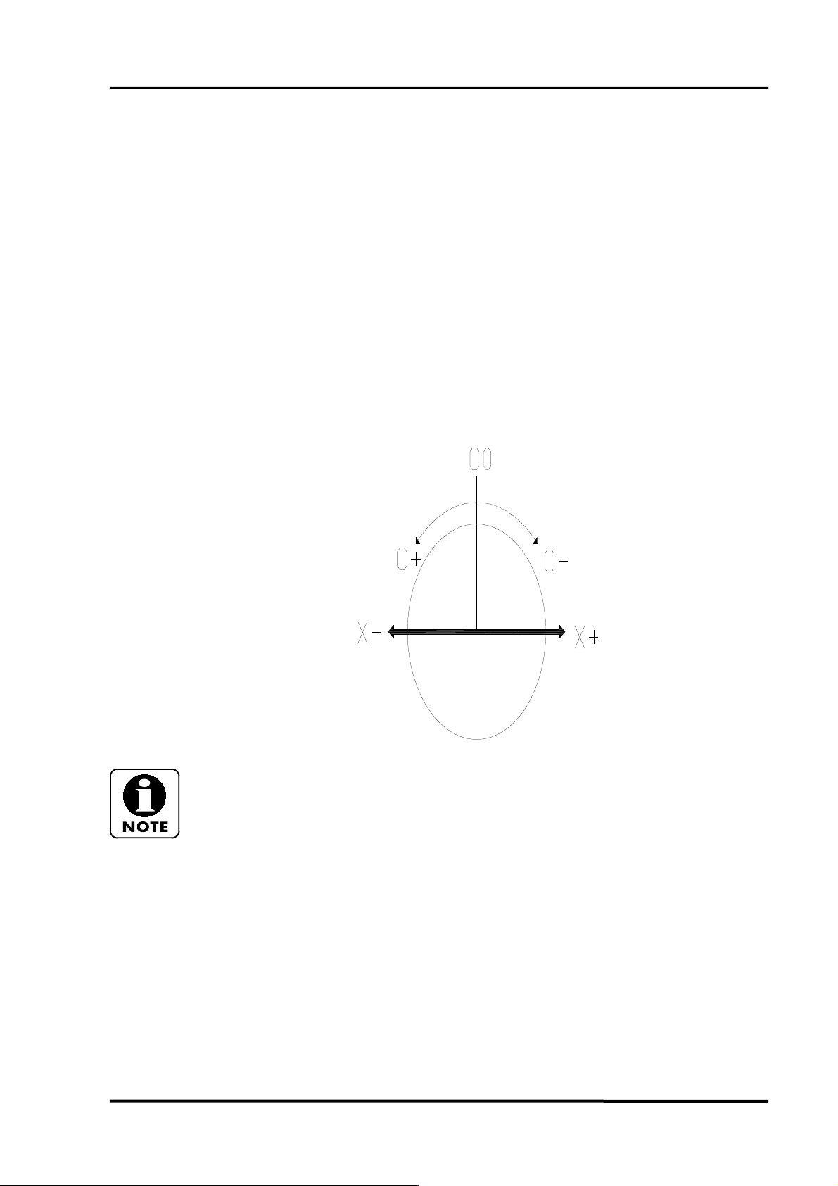
PROGRAMMING MANUAL -84-
Cylindrical Interpolation
Cylindrical interpolation (G107) is used to perform contoured milling operations on the outside
diameter of the workpiece. The Z and C words are used to specify the end points of the moves.
When using cylindrical interpolation, the C word is programmed in degrees.
C is also used to specify the radius of the part in the G107 block which activates cylindrical
interpolation.
The X word is used to program the depth of cut.
1. The following G codes may be used when G107 is active: G1, G2, G3, G40,
G41, G42, G65, and G98.
2. G0 positioning is not allowed when G112 is active.
3. When using G2 or G3, the arc radius is specified using the R word.
4. M40 C axis mode must be active before commanding cylindrical interpolation.
5. The spindle should be oriented to C0 degrees before commanding cylindrical
interpolation. The formula for calculating the value of the C word is shown in the
following program example.
6. If machining in the X axis only, do not activate cylindrical interpolation.
Page 85

PROGRAMMING MANUAL -85-
7. The H word is used to program incremental C axis moves.
8. Machine lock mode MAY NOT BE USED when G107 is active.
9. The unit of command for the C axis, when cylindrical interpolation is used,
degrees, not MM or INCHES.
10. When using cutter compensation during cylindrical interpolation, the same basic
TNRC rules apply as with normal lathe programming. However, the following rules
must also be observed.
The tool radius and the quadrant must be loaded into the geometry offset file. For
cylindrical interpolation, the Z tool offset represents the centre of the cutter and the
tool tip location (Quadrant) will be set to 9.
11. The TNRC start up block (G41 or G42 line) must be programmed after the
cylindrical interpolation command (G107 line) has been activated. For cylindrical
interpolation, the Z axis move must be equal to at least the tool radius entered in the
tool offset file. Program the G40 (TNRC cancel) command before the block
containing the G107 C0 (cancel cylindrical interpolation).
12. Program restart and block restart are not allowed when G107 is active.
13. Specify the feedrate as millimetres per minute.
Page 86
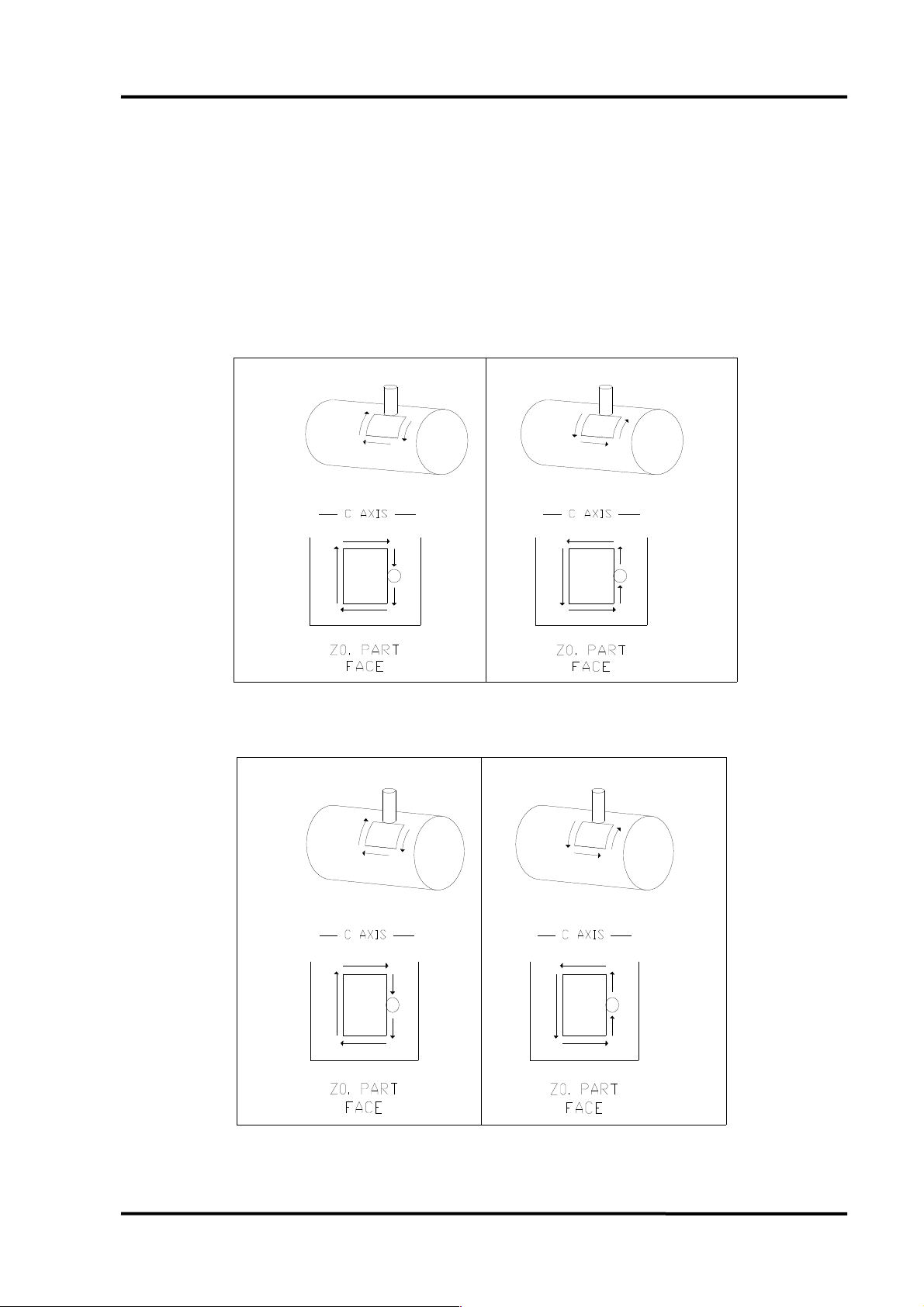
PROGRAMMING MANUAL -86-
Tool nose radius compensation and circular interpolation used
with G107 cylindrical interpolation
The drawings below show the combination of tool nose radius and circular interpolation codes
used with cylindrical interpolation.
The part circumference is viewed laying flat with the part face (Z0) at the base.
G41 Part Right (Cutter Left) G42 Part Left (Cutter Right)
G2 Clockwise G3 Counter Clockwise
G42 Part Left (Cutter Right) G41 Part Right (Cutter Left)
G2 Clockwise G3 Counter Clockwise
Page 87
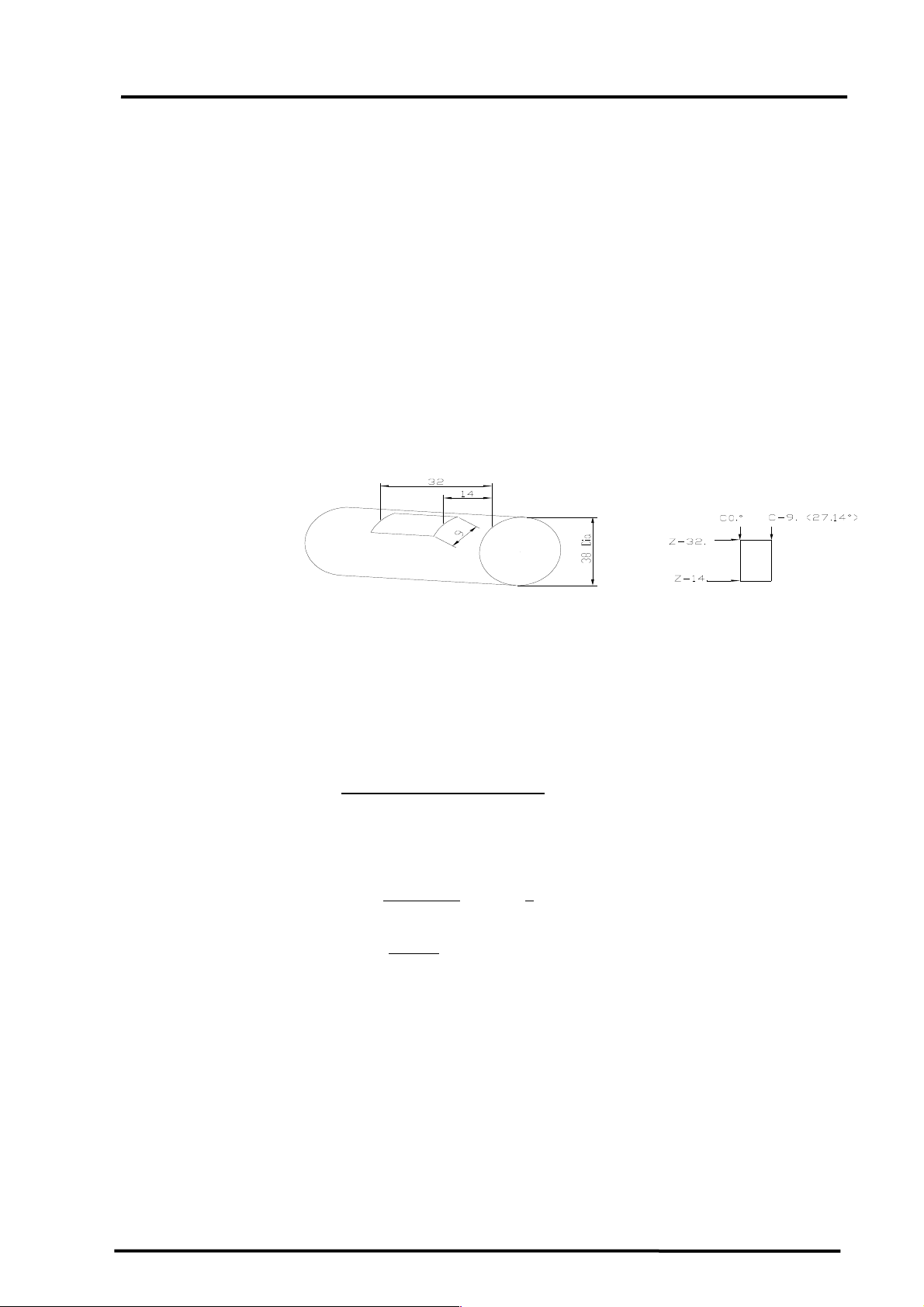
PROGRAMMING MANUAL -87-
Rectangle Engrave Example (Cylindrical Interpolation)
Calculation formula
Circumference = 38 x π =119.396mm
Degrees = mm x 360 eg.9mm
circumference
= 9 x 360
119.396
= 27.14 degrees
Page 88

PROGRAMMING MANUAL -88-
N4 G28 U0.V0.
T404
(RADIAL ENGRAVE)
M5
M43
G28 H0
G97 S3500 M13
G0 G40 G98 G54 X40.Z2.
G1 Z-14. F2500.
G107 C19. G19
X37.F90.
Z-32.
C-27.14
Z-14.
C0.
X40.F1500.
G107 C0.
M15
M40
G0 X150 Z150 M9
M30
Rectangle with Corner Radii Example (Cylindrical Interpolation)
4MM Pocket depth
Tool compensation not used.
Page 89

Calculation formula
PROGRAMMING MANUAL -89-
Circumference = 36 x π =113.11mm
Degrees = mm x 360 eg.9mm
circumference
= 8 x 360
113.11
= 25.46 degrees
N8 G28 U0. V0.
T808
(RADIAL 6MM DIA SLOT DRILL)
M5
M43
G28 H0
G97 S3500 M13
G0 G40 G98 G54 X38.Z2.
G1 Z-14. F2500.
G107 C18. G19
X28.F100.
Z-22.
G2 C-9.55 Z-25. R3.
G1 C-15.91
G2 C-25.46 Z-22. R3.
G1 Z-15.
G2 C-15.91 Z-12. R3.
G1 C-9.55
Page 90
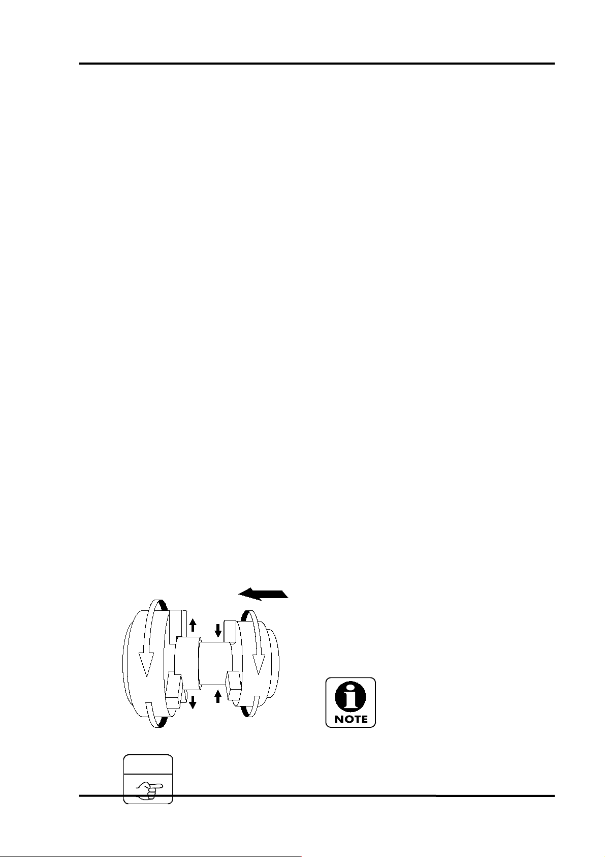
PROGRAMMING MANUAL -90-
COMMAND
G2 C0. Z-15. R3.
X38. F1500.
G107 C0.
M15
M40
G0 X150. Z150. M9
M30
Part Transfer
M160 function is used only to synchronise the main
and sub-spindle speeds.
M161 function disables the phase and
synchronisation mode.
M162 function is used for phase synchronisation
for the main and sub-spindles.
M160, M161 and M162 commands
are only used on machines equipped
with a sub-spindle (S).
M160; ............ Speed synchronisation mode on.
Page 91

PROGRAMMING MANUAL -91-
M161; ............ Phase and synchronisation mode off.
M162; ............ Phase synchronisation mode on.
1- For transferring a workpiece from main spindle to sub-spindle, main and subspindle speed must be synchronised by means of M160 command. If the
workpiece is transferred without activating the synchronisation mode, damage of
the workpiece could result.
2- For transferring an hexagonal bar, main and sub-spindle phase and speed
must be synchronised by means of M160 and M162 command, as otherwise the
transfer operation will not be possible, although it is recommended that if the part
has been turned that you locate on the turned diameter so to achive any
squareness or concentricity tolerences.
3- M162 function can be also used for round parts, but considering that phase
(and speed) synchronisation time is longer and speed synchronisation time, using
only M160 function is recommended when machining round parts.
Page 92

PROGRAMMING MANUAL -92-
EXAMPLE
Program with Billet transfer using M160
These functions are used when the workpiece on main spindle is to be transferred to the subspindle with the synchronisation mode activated.
O0001;
Machining program.
(machining operation on main spindle)
N1000(PART TRANSFER);
G28 U0. V0. M54;………………….Move turret home in X and Y axis
G28 B0. M115;………………...Move turret home in B axis
M110;
G0 G40 G99 G54……………..Preperation G codes
G97 S50 M3;...........................Main spindle rotates at 50 rpm
S50 M113;……………………..Sub spindle rotates at 50 rpm
M160;......................................Synchronise spindles.
M162;......................................Synchronise spindle phase (if required).
Main and sub-spindle speed is synchronised to
50rpm
M119;......................................Sub-spindle chuck open.
M151;……………………………Air blow on sub-spindle
B-???;.....................................Sub-spindle is moved clear fo component (machine co-ordinates)
(First approach)
G1 G98 B-??? F1500;.............Sub-spindle is moved over the workpiece at 1500 mm/min
(Second approach)
M152;......................................Air blow off sub-spindle.
M118;…………………………..Sub-spindle chuck close.
G4 X2.;………………………….Dwell for two seconds.
M69;……………………………..Main spindle chuck open.
G28 B0;...................................Sub-spindle is returned to reference point on B-axis
M161;......................................Synchronisation mode is disabled
M5;………………………………Stop main spindle.
M115;……………………………Stop sub-spindle.
M68;……………………………..Main spindle close.
M1;……………………………….Optional stop
Page 93

PROGRAMMING MANUAL -93-
EXAMPLE
Program with part off and transfer using M160
These functions are used when the workpiece on main spindle is to be transferred to the subspindle with the synchronisation mode activated.
O0002;
Machining program.
(machining operation on main spindle)
N1000(TRANSFER TO SUB SPINDLE AND PART OFF);
G28 U0.V0. M54;………………Move turret home in X axis
G28 B0. M115;………………...Move turret home in B axis
T1010 …………………………..Call part off tool
G0 G40 G99 G54………………Preperation G codes
G97 S50 M3;...........................Main spindle rotates at 50 rpm
S50 M113;………………………Sub spindle rotates at 50 rpm
M160;......................................Synchronise spindles.
M162;......................................Synchronise spindle phase (if required).
Main and sub-spindle speed is synchronised to
50rpm
G0 Z-30………………………….Move to Z Axis part off possition
G0 X50…………………………..Move to X Axis part off possition
M119;......................................Sub-spindle chuck open.
M151;……………………………Air blow on sub-spindle
B-???;.....................................Sub-spindle is moved clear fo component (machine co-ordinates)
(First approach)
G1 G98 B-??? F1500;.............Sub-spindle is moved over the workpiece at 1500 mm/min
(Second approach)
M152…………………………….Air blow off sub-spindle.
M118;……………………………Sub-spindle chuck close.
G96 S200 ………………………Constant surface speed.
G4 X2.;…………………………..Dwell for two seconds.
G1 G99 X20 F.15……………...Part off component.
G28 B0;...................................Sub-spindle is returned to reference point on B-axis
G0 X50…………………………..Move off component.
G28 U0………………………….Move turret home in X-axis.
G28 W0…………………………Move turret home in Z-axis.
M161;......................................Synchronisation mode is disabled
M5;………………………………Stop main spindle.
M115;……………………………Stop sub-spindle.
M1;………………………………Optional stop
Sub spindle machining
Page 94

PROGRAMMING MANUAL -94-
This should be programmed after machining a workpiece on the main spindle and prior to part
ejection.
Machining on the sub-spindle is done at the G30 position.
The following example shows the basic format required for part ejection.
All turning cycles work on the sub spindle but machining is usually done in the X+ and Z+
defined quadrant.
Attenton should be paid to cutter radius compensation on the sub spindle as this the reverse of
normal turning convention.
Part eject
This should be programmed after machining a workpiece on the sub-spindle and prior to
machining a new workpiece on main spindle.
It is assumed that the sub spindle is already at the G30 position, see sub-spindle machining
section.
The following example assumes that the machine is equipped with a bar feed.
Ensure that you have the spring loaded ejector fitted.
N1000; …..……………………..Line number for identification
G28 U0.:.................................Turret home position in X
M115:......................................Sub-spindle is stopped
G4 X0.5:..................................Dwell for half a second
M73;........................................Parts catcher forward.
Workpiece collector operates independently
from turret position.
The B-axis co-ordinate value will be the G30
position, at which the workpiece is released
from the sub-spindle, without causing any
interference with workpiece collector, turret,
etc.
G4 X0.5;..................................Dwell for half a second
M119;......................................Open jaws on sub-spindle.
G4 X3.;....................................Dwell for three seconds to allow the part to be ejected fully.
M74;........................................Parts catcher back.
G28 B0.;..................................Sub spindle home.
G4 X1.;....................................Dwell for one second.
M12;…………………………….Parts counter.
M31;…………………………….Parts count up check.
/M99…………………………….Allows continuous running
M30;…………………………….Activate block skip, then program will stop.
 Loading...