

Dufour Yachts 500 Grand Large Owner's Manual
ENGLISH 26-02-2013 1/78 DUFOUR 500 Grand Large
OWNER’S MANUAL
DESIGN CATEGORY A
IN ACCORDANCE WITH EUROPEAN DIRECT IVE 94/25/EC
AS AMENDED BY EUROPEAN DIRECTIVE 2003/44/EC

ENGLISH 26-02-2013 2/78 DUFOUR 500 Grand Large
This page intentionally left blank
This page intentionally left blank
This page intentionally left blank

ENGLISH 26-02-2013 3/78 DUFOUR 500 Grand Large
Your agent:
Name
is DUFOUR YACHTS’ representative and will give you all the help you need to solve any
difficulties you might have during launching and masting of your boat, as well as for commissioning
and maintenance technical checks. If necessary, he will help you with the administrative process of
registering your boat.
As soon as you become the owner, familiarize yourself with the manual supplied with your boat,
sign and date the receipt acknowledgements below, and give (or send) the last one to your agent.
Owner's Manual receipt acknowledgement to be kept in your Manual
I, the undersigned:
Name
Address
owner of DUFOUR 500 no.
confirm that I have receiv ed the Owner’s Manual for my DUFOUR 500 and accept
its being written in English.
Dated:
Signature:
Detach along dotted line
…………………………………………………………………………………………………………………
Owner’s Manual receipt acknowledgement to be returned to DUFOUR YACHTS
11, Rue Blaise Pascal- 17187 PERIGNY CEDEX- FRANCE
I, the undersigned:
Name
Address
owner of DUFOUR 500 no.
confirm that I have receiv ed the Owner’s Manual for my DUFOUR 500 and accept
its being written in English.
Dated:
Signature:

ENGLISH 26-02-2013 4/78 DUFOUR 500 Grand Large
This page intentionally left blank
This page intentionally left blank
This page intentionally left blank

ENGLISH 26-02-2013 5/78 DUFOUR 500 Grand Large
CONTENTS
INTRODUCTION
.................................................................................................................................................... 7
I. GENERAL INFORMATION
............................................................................................................................. 8
Design category _________________________________________________________________________ 8
Certification _____________________________________________________________________________ 8
Identification ____________________________________________________________________________ 8
Builder's plate __________________________________________________________________________ 9
Degrees of danger _______________________________________________________________________ 9
III. ELECTRICAL SYSTEMS
.............................................................................................................................. 12
Safety and operating instructions for the electrical system ________________________________ 12
Installing new equipment _______________________________________________________________ 12
Batteries_______________________________________________________________________________ 13
Electric windlass _______________________________________________________________________ 13
220 Volts / 110 Volts Installation (ISO 13297 :2000) ________________________________________ 14
IV. GAS INSTALLATION
.................................................................................................................................... 15
Operating advice _______________________________________________________________________ 15
Circuit check (ISO 10239 :2000) __________________________________________________________ 16
Changing the gas cylinder _______________________________________________________________ 16
V. DRAIN & SANITATION SYSTEM
................................................................................................................. 17
Specifications of the drain system (ISO 15083 :2003) _______________________________________ 17
Pressurized fresh-water pump __________________________________________________________ 17
Seacocks _______________________________________________________________________________ 18
Operation of the sea toilets ______________________________________________________________ 18
Holding tank operation (ISO 8099 :2000) ___________________________________________________ 18
VI. FLOODING
..................................................................................................................................................... 19
VII. FIRE PROTECTION
..................................................................................................................................... 19
Installation ____________________________________________________________________________ 19
Safety instructions ______________________________________________________________________ 20
VIII. ENGINE
........................................................................................................................................................ 21
General precautions ______________________________________________________________________ 21
Exhaust gas emissions __________________________________________________________________ 21
Safety _________________________________________________________________________________ 21
Wintering ______________________________________________________________________________ 22
IX. FUEL INSTALLATION
.................................................................................................................................. 22
X. STEERING SYSTEM
....................................................................................................................................... 22
Helm __________________________________________________________________________________ 22
Emergency tiller _______________________________________________________________________ 23
XI. SAILING
......................................................................................................................................................... 23
XII. PREVENTION OF FALLS AND MEANS OF REBOARDING
.................................................................. 24

ENGLISH 26-02-2013 6/78 DUFOUR 500 Grand Large
XIII. LIGHTNING PROTECTION
....................................................................................................................... 24
Maintenance ___________________________________________________________________________ 24
Protection of persons during a storm ____________________________________________________ 24
XIV. ENVIRONMENTAL PROTECTION & SAFETY
....................................................................................... 25
XV. SAFETY FACILITIES
................................................................................................................................... 26
XVI. HANDLING, TRANSPORTING, HAULOUT
............................................................................................. 26
XVII. DOCKING, MOORING AND TOWING
..................................................................................................... 27
Responsibility __________________________________________________________________________ 27
Non-metallic anchor points _____________________________________________________________ 27
XVI. GUARANTEE, TRANSFER OF OWNERSHIP
......................................................................................... 28
1. Presentation plan
........................................................................................................................................ 32
2.
Accommodation layout
................................................................................................................................. 33
3.Deck fittings plan
.......................................................................................................................................... 34
4.Sail diagram
................................................................................................................................................... 36
5.Halyard and sheet operating diagram
..................................................................................................... 38
6.220 V distribution panel diagram
.............................................................................................................. 40
7.220 V circuit diagram
................................................................................................................................... 42
8.220 V circuit diagram with options
........................................................................................................... 44
9.220 V electrical installation diagram
....................................................................................................... 46
10.Fuse location diagram
............................................................................................................................... 48
11.Charging & power circuit diagram
......................................................................................................... 50
12.12 V distribution panel diagram
.............................................................................................................. 52
13.Electrical panel terminal diagram
......................................................................................................... 54
14.12 V electrical installation diagram
....................................................................................................... 56
15.Steering system diagram
.......................................................................................................................... 58
16.Gas system diagram
................................................................................................................................... 60
17.Abandon ship plan
...................................................................................................................................... 62
18.Fresh-water system diagram
.................................................................................................................. 64
19.Drain system diagram
................................................................................................................................ 66
20.Skin fitting location diagram
.................................................................................................................... 68
21.Engine installation diagram
..................................................................................................................... 70
22.Diesel circuit diagram
............................................................................................................................... 72
23.Holding tank installation diagram
.......................................................................................................... 74
24.Lifting diagram
............................................................................................................................................ 76

ENGLISH 26-02-2013 7/78 DUFOUR 500 Grand Large
IINNTTRROODDUUCCTTIIOON
N
DUFOUR YACHTS is pleased to present you with this Manual which will help you get to know your
boat better.
This Manual has been produced to help you use your boat safely and enjoyably. It contains details of the
boat, the equipment supplied or fitted, its systems and information about their use. Read it carefully and
familiarize yourself with the boat before using it.
This Owner’s Manual is not a course in sailing safety or seamanship. If this is your first boat, or you are
changing to a type of boat you are unfamiliar with, for your convenience and safety, make sure you gain
experience handling and using it before taking command. Your agent, your national sailing or cruising
federation or your yacht club will be happy to give you information about sailing schools or qualified
instructors in your area.
Ensure that forecast wind and sea conditions correspond to the design category of your boat, and that you
and your crew are capable of handling the boat in these conditions. Even when your boat is suitable for
them, the sea and wind conditions corresponding to design categor ies A, B, and C vary from severe storm
for category A to severe conditions for the top end of category C, subject to dangers of abnormal gusts or
waves; these are dangerous conditions in which only an experienced, trained crew in good condition,
sailing a properly-maintained boat, can sail in a satisfactory manner.
This Owner's Manual is not a detailed maintenance or repair guide. In the event of problems, consult the
boatbuilder or the boatbuilder's representative. If a maintenance manual is provided, be sure to use it.
Always employ the services of an experienced professional for maintenance, fitting accessories, or
modifications. Modifications that could affect the characteristics of the boat must be assessed, carried out
and documented by qualified personnel. The boatbuilder cannot be held responsible for modifications
made without their approval.
In certain countries, a skipper’s licence or authorization is required, or special regulations are in force.
Always maintain your boat correctly and make allowance for deterioration due to age or resulting, where
applicable, from heavy or unsuitable use. Any boat, however sturdy it is, can be severely damaged if it is
used incorrectly. This is incompatible with safe sailing. Always suit your speed and heading to the
prevailing sea conditions.
If your boat is equipped with a life-raft, read its instruction manual carefully. The crew must have on board
all the safety equipment (life-jackets, harnesses, etc.) corresponding to the type of boat, weather
conditions, etc. In some countries, this equipment is mandatory. The crew must be familiarized with the use
of all the safety equipment and with emergency safety procedures (man overboard recovery, towing, etc.);
training sessions are regularly organized by sailing schools and clubs.
It is recommended that all persons wear appropriate buoyancy aids (life-jackets, personal flotation devices)
when on deck. It should be noted that in certain countries, it is compulsory to wear a buoyancy aid
(complying with national regulations) at all times.
KEEP THIS MANUAL IN A SAFE PLACE AND PASS IT ON TO THE NEW OWNER IF YOU
SELL THE BOAT.
WARNING: Our boats are regularly improved in the light of our customers’ experiences and
researched by the shipyard, and so the specifications given in this Owner’s Manual are not
contractually binding and may be changed without notice and without any obligation to update.
This manual is intended to cover as much information as possible, so certain equipment or
paragraphs might not apply to your boat. In case of doubt, please refer to the inventory which
should have been given to you by your agent when you placed your order.

ENGLISH 26-02-2013 8/78 DUFOUR 500 Grand Large
II.
.
GGEENNEERRAALL IINNFFOORRMMAATTIIOONN
Design category
Your DUFOUR 500 comes under the OCEAN-GOING design category A.
Under conditions of normal use, your boat is designed to sail in waves with a significant height
exceeding 4 m and winds of force 8 or above on the Beaufort scale, and to withstand the severest
conditions.
This sailing capability is equally dependent on the skills of the crew, their physical capacities, the
maintenance of the boat and its equipment.
So always take care before putting to sea.
DUFOUR YACHTS is not able to guarantee perfect functioning of the boat in exceptional sea conditions
(violent storms, hurricanes, cyclones, waterspouts, etc.)
SUMMARY OF DESIGN CATEGORIES
Check weather information before putting to sea: Take to the sea, don’t take risks!
In port: every day, the Harbor Master's Office posts weather bulletins and forecasts for the
next few days.
Météo France on 0836 68 08 08
Navifax - direct on 0836 70 18 52
VHF: CROSS transmit several bulletins per day, preceded by an announcement on Channel
16.
Certification
DUFOUR YACHTS has chosen the Institut pour la Certification et la Normalisation dans le Nautisme
as the notified body for verifying that your boat complies with European directive 94/25/EC, as per
module B.
Identification
The hull identification number is located on starboard side of transom. It contains a series of letters and numbers that begin with FR-DUF...
Design
category
Type of sailing
Wind strength
(Beaufort)
Wind
speed
Significant height
to be taken into
account
A Ocean-going Greater than 8 Up to 28 m/s Higher than 4 m
B Open sea
Up to and
including 8
Up to 21m/s
Up to and including
4 m
C Inshore
Up to and
including 6
Up to 17 m/s
Up to and including
2 m
D Sheltered waters
Up to and
including 4
Up to 13 m/s
Up to and including
0.5 m

ENGLISH 26-02-2013 9/78 DUFOUR 500 Grand Large
Builder's plate
Design category = A : Ocean-going (see 1.1)
Max. number of people aboard:
category A = 11
category B = 11
category C = 14
category D = 14
WARNING
Do not exceed the maximum recommended number of people. However many people there are
aboard, the total weight of the people and equipment must never exceed the maximum
recommended loading.
Max. recommended load:
category A = 2665 kg
category B = 2665 kg
category C = 2665 kg
category D = 2665 kg
WARNING
When loading the boat, never exceed the recommended maximum load. Always load the boat
carefully and distribute the weight in a suitable manner in order to maintain the theoretical trim
(approximately horizontal). Avoid placing heavy loads high up.
CE 0607
Degrees of danger
DANGER
Indicates the existence of an extreme intrinsic risk that may give rise
to a high probability of death or serious injury if appropriate
precautions are not taken.
WARNING
Indicates the existence of a risk of injury or death if appropriate
precautions are not taken.
CAUTION
Indicates a reminder of safety practices or attracts attention to
hazardous practices that may cause injuries, or damage to the boat,
its components or the environment.
: Recommended by the builder for navigation in sea
conditions for category for which it was built.
: CE mark indicating that the boat complies with all the
requirements of the Directive. The sequence of numbers is
the Certification institution's code, in this case the ICNN
(Institut pour la Certification de la Normalisation dans le
Nautisme), (see also: Safety Co mpli ance Declaration).).
: recommended by the builder, including the weight
of all persons aboard, the provisions and personal
effects, and of all equipment not included in the light
displacement weight of the boat, excluding the
content of the tanks.
Part of this information is given on the builder’s
plate attached to the boat. A full explanati o n o f
this information is given below.

ENGLISH 26-02-2013 10/78 DUFOUR 500 Grand Large
II. PRINCIPAL SPECIFICATIONS
Model:
DUFOUR 500
Grand Large
Builder
Dufour Yachts
11, Rue Blaise Pascal
17187 Périgny cedex
FRANCE
Designer:
Umberto Felci
Interior design
DUFOUR Design
Design category
A
Notified body No.
CE/0607
Engine #
Primary means of propulsion
Sail
L
max
LOA*
15.10 m
LH
Hull length*
14.75 m
B
max
Maximum beam*
4.78 m
BH
Hull beam*
4.78 m
HA
Max. air draft*
21.40 m
T
max
Draft (deep ballast)*
2.30 m
Deep ballast weight
4,042 kg
Standard mainsail area (approximate)
48 m²
Genoa area (approximate)
52 m²
Maximum permissible on-board engine power
110 hp / 81 kW
Water capacity excluding 40 L water-heater
(approximate)
680 L
Diesel capacity (approximate)
500 L
Holding tank
100 L (+50 L option)
Engine battery
140 Ah
Auxiliary battery (2 as standard + 2 as option)
280 Ah (+280 Ah option)
MLC
Light displacement
15,245 kg
MMO
Minimum displacement condition
15,232 kg
ML
Maximum load
3,760 kg
Total weight of liquids (all tan k s full)
1095 kg
M
LDC
Maximum load displacement
19,005 kg
* The above dimensions are in compliance with ISO 8866, i.e.:
L
max
: maximum length of the boat including parts that are normally fixed, such as rollers, pulpits,
etc.
L
H
: maximum length of the boat including the structural and integral parts of the boat, and
excluding the removable parts.
B
max
: beam of boat measured between the outermost parts and possibly including removable
parts such as rubbing strakes, guard rails, etc.
B
H
: beam of boat measured between the outermost fixed parts and excluding all removable
parts
HA : vertical distance between the waterline in light displacement condition and the highest point
of the ma st structure. (this measurement does not take into account the equipment such as
lights and antennas that may be fixed to the top of the mast)
T
max
: the max. draft is measured at the lowest point of the ballast equipping the boat

ENGLISH 26-02-2013 11/78 DUFOUR 500 Grand Large
M
L
: the Maximum Load is the sum of the recommended maximum load (see builder's plate) and
the total mass of liquids (consumable or non-consumable)
Nota bene: due to the trim and loading of the boat, it is not usually possible to use the whole
of the various tank capacities for fresh water and diesel. You are recommended to maintain
a diesel reserve of 20%.
Specific information
This boat has been evaluated with the aid of the stability index (STIX), a global safety
measurement with regard to stability, which considers the effects of the boat's length, its
displacement, the hull proportions, the stability characteristics and resistance to flooding.
The maximum total load is the sum of the recommended maximum load and the total mass of
liquids (see ISO 12217-2:2002).
The second index (AVS) represents the angle of disappearance of stability in degrees.
Minimum sailing
condition (MMO)
STIX
45,8
AVS
116,5°

ENGLISH 26-02-2013 12/78 DUFOUR 500 Grand Large
IIIIII.. EELLEECCTTRRIICCAALL SSYYSSTTEEMMSS
Safety and operating instructions for the electrical system
WARNING
Improper use of the DC and/or AC systems may give rise to fire or explosion hazards.
Improper use of the AC systems may give rise to the risk of electrocution.
Always:
●
Check the condition of the batteries (charge and electrolyte level) and the charging system
before putting to sea.
● Disconnect and remove batteries for wintering.
● Do not let battery voltage drop below 10.5 V during wintering.
● Carry spare bulbs for all navigation lights and interior lighting. Respect power ratings,
particularly for navigation lights.
● Check operation of the navigational instruments.
● Check operation of navigation lights before night sailings.
Never:
● Work on an electrical instal l ation that is live.
●
Make any modification to an installation and the associated circuits, unless it is carried out
by an electrician qualified in marine electrics.
● Change or modify the breaking capacity of overload protection devices.
● Replace electrical apparatus or equipment with units exceeding the rated capacity without
uprating the wiring and protection.
● Leave the boat unattended when the electrical installation is powered, with the exception
when applicable of the automatic bilge pump and the fire or theft protection circuits.
If a fuse or circuit-breaker blows continually, you should consult a specialist to determine the
cause of the short-circuit.
Installing new equipment
Since 1 January 1996, electrical equipment is subject to the European “electromagnetic
compatibility” directive (Ref 89/336/CEE). So new equipment being installed must meet this
standard and bear the CE mark. Equipment must also be supplied with a compliance
certificate and instructions for use.
In the case of 220 or 110 V installations, use only double-insulated or earthed equipment.
When such equipment is being installed, respect the fitting instructions (conductor size,
protection).
To avoid maintenance problems, be sure to enter in the manual any modifications that may
have been made to the electrical circuits.

ENGLISH 26-02-2013 13/78 DUFOUR 500 Grand Large
Batteries
The battery facilities consist of two 140 Ah auxiliary batteries as standard (plus 2 x 140 Ah
optional batteries) and one 140 Ah battery for engine starting.
Their capacities have been designed to handle the power requirements of the on-board
accessories. To avoid any problems, it is necessary to keep a close eye on the maintenance
and correct charging of the batteries.
ATTENTION!
● When installing new electrical appliances, take care that the overall consumption of these
appliances remains within the capacity of your batteries.
● Always disconnect the negative (-) battery terminal before the positive (+) terminal.
● Never allow a conductive object (tools, etc.) to bridge across the two battery terminals.
● When handling batteries, keep them horizontal to avoid spillage of electrolyte. Wear
gloves and protective clothing that will prevent any risk of contact with electrolyte in the
event of a leak.
● In the event of electrolyte splashes, rinse the affected part of the body copiously and
consult a doctor.
Electric windlass
ATTENTION!
It is essential to run the engine with the throttle slightly open when using the electric
windlass.

ENGLISH 26-02-2013 14/78 DUFOUR 500 Grand Large
220 Volts / 110 Volts Installation (ISO 13297 :2000)
DANGER!
The on-board 220V installation is protected by a circuit breaker and fitted with a residual
current device.
The wiring of additional 220 V on-board accessories must be carried out by professionals,
and the master circuit-breaker uprated i f nec ess ar y.
- Disconnect the boat’s power supply when system is not in use.
- Connect the metal cases or housings of installed electrical equipment to the boat’s
protective conductor (green or green / yellow wire).
- Use double-insulated or earthed electrical appliances.
ATTENTION!
When the boat is moored at the quayside, set the isolator to the "off" position.
DANGER!
Your boat is delivered without a boat / shore power supply cable or shore connection plug.
The cable used must be designed for exterior use. Its cross-sectional area must be
appropriate for its length and the rating of the main circuit-breaker (see electrical diagram).
The plug must be suitable for the socket on the shore (if necessary, seek the advice of a
professional). It should be as close as possible to the IP 67 / IEC529 type
● Switch off the shore supply at the on-board isolator before connecting or disconnecting
the shore/boat supply cable.
● Connect the shore/boat supply cable at the boat end before connecting it to the shore
outlet.
● Disconnect the shore/boat supply cable at the shore outlet before disconnecting it at the
boat end.
● Close the shore outlet cover properly.
Never:
● Make modifications to the shore supply cable; you must only use compatible connectors.
● Swim close to a boat connected to a shore supply socket:danger of electrocuti o n!
Location of the 220 V master circuit-breaker: starboard cockpit locker.
Have the system inspected at least every two years.
During haul-out maintenance, set to the ‘on’ position in order to have earth [grounding]
protection via the shore socket.
WARNING
Never let the end of a ship/shore supply cable dangle into the water. It may create an
electrical field that could injure or kill nearby swimmers.

ENGLISH 26-02-2013 15/78 DUFOUR 500 Grand Large
IIVV.. GGAASS IINNSSTTAALLLLAATTIIOONN
Operating advice
- Read carefully all instructions for the cooker and regulator before use or maintenance.
- Ensure that the gas cylinder and regulator are in accordance with the requirements of the
cooker (flow rate, pressure, type of gas) and with the regulations in force in the country
where it is being used.
- Make sure the appliance gas taps are closed before opening the valve on the cylinder.
WARNING
● Fuel-burning naked-flame appliances use up the oxygen in the cabin and release
combustion products inside the vessel. Proper ventilation is necessary: open the nearest
deck hatch or porthole along with the companionway hatch when appliances are in use.
● Never block the ventilation openings and check that appliances with flues are working
properly.
● Do not use the cooker/oven as a means of heating.
- Do not obstruct quick access to the elements of the gas installation (cylinder locker, shut-
off val ve).
- The gas cylinder must always be stowed in the sealed, ventilated space provided. The
same applies to spare or empty cylinders. Keep close to hand the protective mechanisms,
lids or caps. No other equipment must be stowed in this space.
- Never leave the boat u nattended when gas appliances are on.
- Close all valves in the circuit when the boat is left empty (shut-off valve, regulator valve),
even if the cylinder is believed to be empty. In the case of the latter, disconnect the
valves.
- After the boat has been shut up, never smoke when going below, and ensure that there is
no smell of gas.
- If you smell gas, close the circuit valves and the cooker taps, ventilate the boat, and find
the leak before using the installation again.
WARNING
In the event of an
emergency, the circuit valves must be closed immediately (in particular, in
the event of fire).
ATTENTION!
Certain precautions must be taken to avoid any contact with naked flames or other hot areas.
Never use the cooker when there is a probability of high roll angles or permanent heel
angles (if the cooker is not suspended from gimbals).

ENGLISH 26-02-2013 16/78 DUFOUR 500 Grand Large
Circuit check (ISO 10239 :2000)
Check the LPG installation for leaks before use.
Check the seals for all connections as fol l ows:
- close valves on all devices
- open gas cylinder valve
- allow gauge pressure to stabilize
- close gas cylinder valve
- observe pressure gauge value for 3 minutes; if it drops, there must be a leak: do not use
devices
-search for leaks using a leak detection device or using soapy water (cylinder valve open,
other valves closed) or any other foaming solution as per standard EN14291
- have leaks repaired before using installation again; repairs and modifications to the circuit
should be carried out by a competent person.
ATTENTION!
Do not use solutions containing ammonia.
DANGER!
Never use a flame to look for leaks.
Flexible hoses must be:
- checked regularly, at least once a year,
- replaced if the expiry date marked on the hose is passed,
- replaced five years after the date of manufacture that may be marked on them,
- replaced in the event of damage.
Changing the gas cylinder
DANGER!
● Close the cooker valves and those on the front of the cooker before changing the gas
cylinder.
● Do not smoke or use a naked flame during replacement of the gas cylinder.
● Ensure that the compartment housing the gas cylinder is well ventilated when replacing it.
WARNING
In the case of an LPG installation:
● Never leave the boat unattended when appliances using LPG are turned on.
● Refrain from smoking or using a naked flame while LPG cylinders are being changed.
● Close the valve on the empty cylinder before disconnecting it for replacement.

ENGLISH 26-02-2013 17/78 DUFOUR 500 Grand Large
VV.. DDRRAAIINN && SSAANNIITTAATTIIOONN SSYYSSTTEEMM
Specifications of the drain system (ISO 15083 :2003)
Pump type
Theoretical flow
rate
Manual
38 L @ 45
strokes/minute
Electric 12V
2000 L / h
Read carefully the operating and maintenance instructions for your boat's bilge pump.
WARNING
The bilge pump system is not designed to handle water entering as a result of holing of
the hull. It is intended to remove water coming from spray, leaks from seacocks or other
moderate leaks.
ATTENTION!
● The level of bilge water must be kept to a minimum.
● Ensure that bilge pumps are in working order before putting to sea.
● Regularly clean away any debris that might obstruct the sump well and the pump intake
points or strainers.
If the watertight bulkheads that isolate the fore- and after-peaks are fitted with valves, these
should normally be kept closed and only opened in order to drain the water into the main
bilge.
● Know where to find the hand pump and its handle.
● Know where to find the switch for the electric pump on the electrical panel.
Pressurized fresh-water pump
Fresh water is supplied to the sink and washbasins by an electric pump. A filter is installed
upstream of the pump, and must be cleaned regularly.
Never allow the pump to run if the tank is empty. Refill the tank before using the water
supply again.
The tanks can be sterilized using Clonazone® tablets (available from pharmacies). Every
year, remove the inspection covers and clean them by filling with water containing a
bactericidal detergent; leave it to act for a few hours, then rinse two or three times. During
wintering, fill the tanks up completely to avoid the development of algæ or bacteria, or if there
is a risk of freezing, empty the tanks; never use anti-freeze.
Hot water is produced by a water heater connected to the engine cooling circuit and the shore
electric supply.
After the water heater has been emptied, make sure that the heating element is covered
before power is re-applied.

ENGLISH 26-02-2013 18/78 DUFOUR 500 Grand Large
Seacocks
Seacocks are of the ¼-turn type:
- OPEN position: handle in line with seacock body,
- CLOSED position: handle perpendicular to seacock body.
ATTENTION!
● Never interfere with the tightening of the seacocks to the hull. In the event of a leak,
consult a professional.
● In bad weather or when leaving your boat, close all the sanitation system seacocks.
● Keep seacocks closed when not in use.
● During wintering, clean and rinse the seacocks and skin fittings. Inspect the brass
accessories; slight surface corrosion is normal.
● In the event of more serious corrosion, consult your agent.
Operation of the sea toilets
- Open the seawater inlet seacock.
- Open the bowl emptying seacock.
- Set the lever to the "FLUSH" position.
- Operate the pump.
- To empty the bowl and avoid any water slopping when heeling, set the lever to the "DRY
BOWL" position.
- Operate the pump until the bowl is dry.
- Repeat these flushing / bowl draining operations as many times as is necessary to ensure
complete emptying of the pipes.
- When toilets are not being used, set the lever to the "DRY BOWL" position, or the "CLEF"
("KEY") position for cer tai n mod el s.
- Close seacocks after use, as the toilet is below the waterline.
- Change the toilet seals regularly.
Holding tank operation (ISO 8099 :2000)
ATTENTION!
Where a holding tank is fitted, take care to lock the evacuation tank, to avoid any accidental
discharge during wintering.
- The sewage tank (45 L) is operated using the toilet hand pump.
- The contents of the toilet bowl are discharged straight into the holding tank.
- Periodically check that the vent is working properly.
- A deck plate is provided for emptying the tank.
- The discharge valve can be sealed in the closed position using a padlock.
- Once a season, arrange to clean out the tank using a biodegradable disinfectant chemical.
Leave the system empty if the vessel is to be left in below-freezing temperatures.
Vanne ouverte
Vanne fermée
Seacocks open
Seacocks closed

ENGLISH 26-02-2013 19/78 DUFOUR 500 Grand Large
VVII.. FFLLOOOODDIINNGG
To avoid the risks of the boat flooding:
- Before putting to sea, always check that portholes, deck hatches and any other
openings that could allow flooding are shut.
- W hen sailing, close all seacocks when they are not being used, except the engine
water intake.
- Do not exceed the recommended maximum load.
- The level of the water in the bilge must be kept to a minimum.
- Avoid placing heavy loads high up in order not to affect stability.
Periodically check:
- The seals of skin fittings, seacocks and pipes.
- Proper emptying of the cockpit drains
- The seals of cable glands and sail-drive gaskets.
WARNING
Cockpit locker lids must be fastened shut before putting to sea. This is particularly
important for those lockers that represent a major flooding risk
VVIIII.. FFIIRREE PPRROOTTEECCTTIIOONN
Installation
Since fire extinguishers are subject to specific national regulations, they are not supplied
with your boat.
However, when it is in service, this boat must be equipped with portable fire extinguishers
with the following extinction capacities and installed in the following locations (see
diagram, appendix 15):
- No. 1 - galley - firefighting capacity 1 kg - 5A34B
- No. 2 - chart table - firefighting capacity 1 kg - 5A34B
- No. 3 - cockpit locker, within reach of the helmsman - firefighting capacity 1 kg 5A34B
If you choose to install a carbon dioxide fire extinguisher, be aware that it may only be
placed in living quarters where flammable liquids are present (e.g., galley) or where there
is powered electrical equipment (e.g., electric motors, battery compartment, electric control
panels).
Only compatible replacement parts should be used in the fire protection system. They
must bear the same markings and be technically equivalent.
In addition, a fire blanket should be stored close to the galley — very useful particularly in
the event of a pan fire involving oil (e.g., saloon settee).
If non-flammable materials are stored in the engine compartment, care should be taken to
ensure that there is no risk of them falling into the machinery, and they must not obstruct
access to the engine compartment or its exhaust.

ENGLISH 26-02-2013 20/78 DUFOUR 500 Grand Large
WARNING
If a CO2 extinguisher is fitted, the following information must be displayed close to its
location:
« This extinguisher contains CO2 - use only on electrical or cooker fires. To avoid
suffocation after discharging, leave the area immediately. Ventilate before reentering.”
Do not open the engine compartment immediately after putting out a fire, to avoid the release
of toxic smoke or spraying of burning materials (oil, water).
Safety instructions
ATTENTION!
It is the responsibility of the owner / skipper to:
● Have firefighting equipment checked in accordance with the stipulations of the boatbuilder
and the regulations in your country.
● Replace firefighting equipment if it has expired or been discharged with extinguishers of
equal or greater capacity.
● Point out to the crew members:
- the location and operation of firefighting equipment
- the location of the engine compartment discharge orifice
● Ensure that firefighting equipment is readily accessible whenever the boat is occupied.
● Always keep the bilges clean and check that there is no fuel vapour or gas.
● Signal the evacuation paths
Never:
● Obstruct gangways to emergency exits (deck hatches).
● Obstruct safety controls (gas valves, fuel valves, electrical switches).
● Obstruct fire extinguisher stowages.
● Leave the boat unattended with a cooker or heater alight.
● Use a gas lamp in the boat.
●
Fill a fuel tank or change a gas cylinder while the engine is running, or the cooker or heater
are in operation.
● Smoke while handling fuel or gas.
● Fit free-hanging curtains near the cooker or any other appliance using a naked flame.
● Store flammable products in the engine compartment.
●Modify any of the boat’s installations (especially the electrical, fuel or gas installations), or
allow any unqualified person to modify these installations.

ENGLISH 26-02-2013 21/78 DUFOUR 500 Grand Large
VVIIIIII.. EENNGGIINNEE
Regular maintenance must be carried out in accordance with the engine manufacturer’s
recommendations. Read carefully the engine operating instructions that come with the boat.
Do not hesitate to consult your agent or a qualified professional. In particular, follow the
instructions for winter i ng .
General precautions
ATTENTION!
Do not use sail and engine if the heel angle is more than 10°.
Any engine change must respect the capacities of the boat and be performed by an engineer
specializing in marine mechanics.
After first launching and tensioning of rigging, check the alignment of the propeller shaft or
the sail-drive flange ring.
● Ensure that the ventilation orifices (vents, engine ventilation grilles) are clear.
● Ensure that the cooling circuit water intake seacock is open, and that water is coming out
of the engine exhaust.
● Boats fitted with rotating seal stern gland: bleed the air from the gland after each launch.
Place the throttle in neutral before starting the engine in order to prevent boat movement
and/or rotation of the propel l er .
On subsequent launches, a brief check of propeller fixing can be made. Incorrect operation of
the folding propeller will lead to vibration
Regularly check the condition of the anodes and ensure that they are suitable for the boat’s
environment (fresh water, salt water). Change the anodes every year. The 3 anodes have an
average life of 1–2 years.
These anodes are made of zinc. It is essential not to use magnesium ones. Impressed current
cathodic protection systems should not be used
If the anodes are not eroded, you need to check:
- that they have not been painted over,
- that they are correctly fixed and in contact with the hull,
- and that they are indeed made of zinc.
Exhaust gas emissions
DANGER!
Internal combustion engines produce carbon monoxide. Prolonged exposure to exhaust
gasses can have serious consequences, and may even cause death.
Safety
DANGER!
In order to avoid all risk of serious injury from the propeller, the engine must not running
when there are people swimming near the boat.
Whenever possible, the engine must be stopped for any engine maintenance or checking
operations. If this is impossible, then particular care must be taken with moving parts
(propeller shaft, belts, etc.) to avoid any danger of injury.

ENGLISH 26-02-2013 22/78 DUFOUR 500 Grand Large
Wintering
Read carefully the operating and maintenance instructions for the engine that come with your
boat along with the instructions for wintering.
In the absence of other instructions, proceed as follows :
- Close the engine water intake seacock.
- Disconnect the pipe from the engine water intake seacock.
- Drain the seawater circuit.
- Place the pipe into a drum of –25° anti-freeze coolant.
- Run the engine until the fluid comes out of the exhaust.
- At the end of this operation, re-connect the pipe to the seacock.
- Attach a notice to the electrical panel and the battery isolator to the effect that the
engine water intake seacock is closed.
IIXX.. FFUUEELL IINNSSTTAALLLLAATTIIOONN
In the event of deterioration, flexible fuel pipes must be replaced by pipes bearing the same
markings. Do the same for all fuel lines.
ATTENTION!
● Depending on the trim and loading of your boat, the whole of the nominal fuel capacity may
not be usable. Always maintain a 20% res erve for safety.
● Avoid contact between flammable materials and hot parts of the engine.
● ● Clear up any fuel overflows in the boat when filling the tanks.
Never:
●- Store flammable materials in unventilated spaces.
●- Smoke while filling tanks.
● - Obstruct ventilation openings (vents, engine ventilation grilles). Ensure that they are kept
clear.
● - Modify the installation, unless this is carried out by a technician qualified in this field.
XX.. SSTTEEEERRIINNGG SSYYSSTTEEMM
The steering system plays a vital role in the safety and comfort of your boat.
Helm
The DUFOUR 500 is fitted, as standard, with an emergency tiller and, as option, with a dual wheel
with a system of rudder cables and chains
Checks to be carried out periodically: Check the play in the various elements (rudder
stock/bearings, tension and wear in mechanical components) and grease the sprocket and
chain if necessary.
In the event of any doubt or problem, consult your agent.

ENGLISH 26-02-2013 23/78 DUFOUR 500 Grand Large
Emergency tiller
ATTENTION!
● The Dufour 500 is equipped with an emergency tiller that must be kept readily accessible
— we recommend its stowage in a cockpit locker.
● It is only designed for sailing at reduced speed in the event of damage to the helm.
To use it:
- Unscrew the deck-plate to reveal the head of the rudder stock.
- Fit the tiller onto the head of the rudder stock.
XXII.. SSAAIILLIINNGG
WARNING
In all situations, make sure you adapt the speed of your boat to the surrounding conditions,
and always maintain a margi n for safet y . Pay par ti c ular att en ti on to:
● the state of the sea, currents, wind strength
● traffic
● manoeuvres in ports
● manoeuvring through mooring areas
● Obey the rules of priority as set out in the Rules of the Road and imposed by COLREG.
● Ensure that you always have sufficient stopping or maneuvering distance if necessary to
avoid a collision.
● Respect speed limit areas.
● Out of courtesy and for the safety of other vessels, take care not to create excessive wash
close to other craft.
● Carefully secure any mobile items when the boat is in motion.
WARNING
● You should fit your boat with life-lines. Anchor-poi nts ar e provided on the deck. Please
refer to the deck fittings plan for your boat.
● Your boat’s stability has been designed to take into account the weight of the boat in light
displacement condition, the standard on-board equipment and the boatbuilder's catalogue
options.
Any alteration to on-board weight distribution (for example: adding a radar, changing an
engine, etc.) can have an effect on your boat’s stability, trim, and performance.
Breaking waves represent a significant threat to stability.
Towing a boat creates significant overloading, adversely affecting the stability of your boat.
● Never:
Raise heavy weights using the boom.
ENGLISH 26-02-2013 24/78 DUFOUR 500 Grand Large
XXIIII.. PPRREEVVEENNTTIIOONN OOFF FFAALLLLSS AANNDD MMEEAANNSS OOFF
RREEBBOOAARRDDIINNGG
When sailing, you are recommended to walk only on deck zones intended for this purpose. These
zones (catwalks, cockpit, roof, side benches, etc.) are covered with an anti-slip or teak coating,
depending on the option chosen, for moving around in safety.
You are also recommended to use the harnesses, using the various points of attachment listed in
the deck fittings plan and according to the sea, wind or heel conditions on the boat.
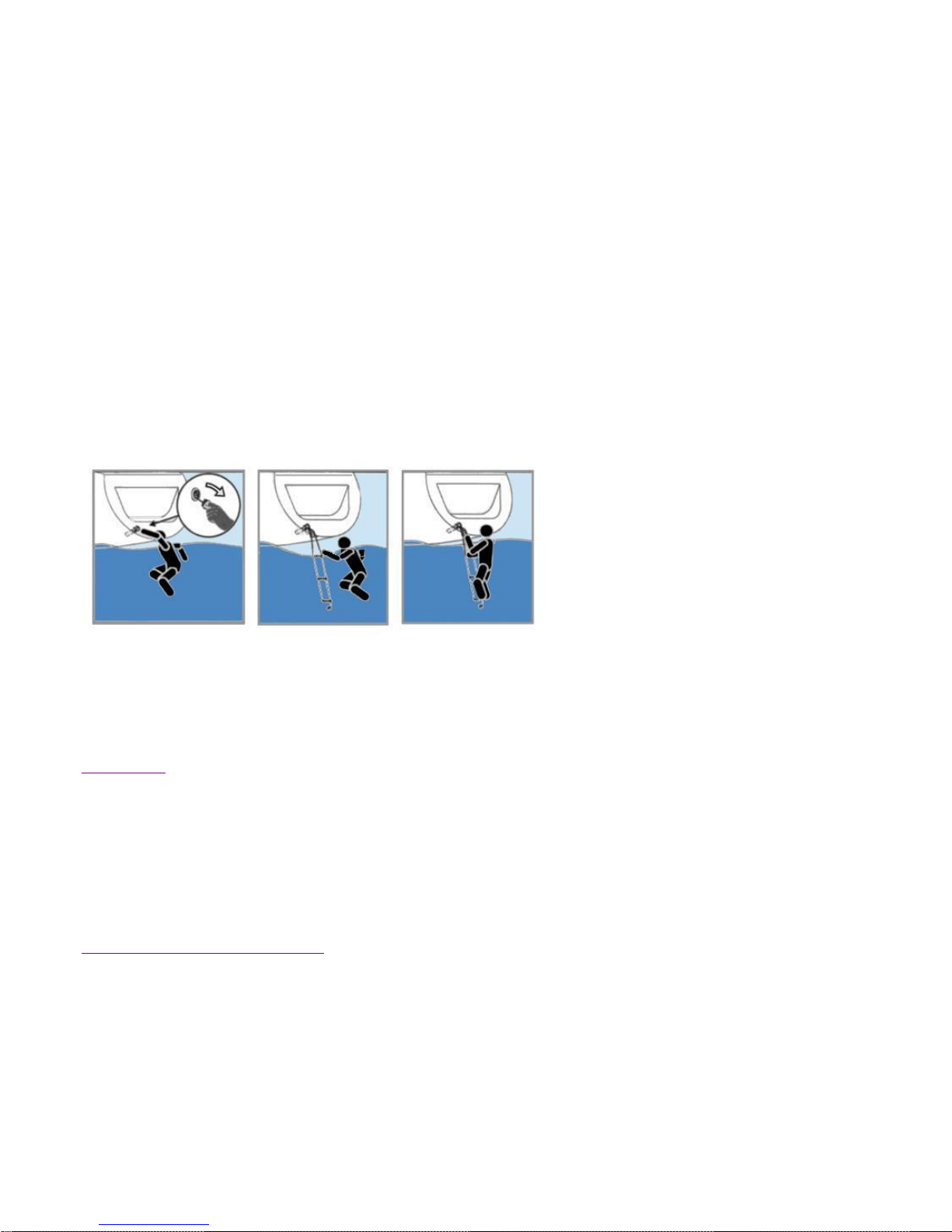
The DUFOUR 500 is equipped with a reboarding ladder integrated in the transom hatch. To use
the ladder, lower the transom hatch by releasing the tow-line then remove the ladder from its
housing and unfurl into position.
A safety ladder is also provided in the event of an emergency. It is located on the transom, and
accessible from the water .
XXIIIIII.. LLIIGGHHTTNNIINNGG PPRROOTTEECCTTIIOONN
Your boat is protected against lightning. The rigging is electrically grounded. Nonetheless, for your
safety, it is necessary to respect certain precautions.
Maintenance
If the vessel has been hit by lightning:
- The protection installation must be inspected to detect physical damage and check
the integrity of the device, as well as the continuity of the grounding protection.
- The compasses, electrical and electronic devices must be examined in order to
ascertain if damage or calibration changes have occurred.
Protection of persons during a storm
 Loading...