

Dufour Yachts 40 Performance Owner's Manual
ENGLISH Date: 2009.09.29 Page 1 / 79 Dufour 40 Performance
OWNER’S MANUAL
DESIGN CATEGORY OF YACHT A
IN ACCORDANCE WITH EUROPEAN DIRECTIVE 94/25/CE
AS AMENDED BY EUROPEAN DIRECTIVE 2003/44/CE

ENGLISH Date: 2009.09.29 Page 2 / 79 Dufour 40 Performance
This page intentionally left blank
***
This page intentionally left blank
***
This page intentionally left blank
***

ENGLISH Date: 2009.09.29 Page 3 / 79 Dufour 40 Performance
Your agent
Name
is DUFOUR YACHTS’ representative and will give you all the help you need to solve any difficulties
you might have during launching and masting of your boat, as well as for commissioning and maintenance
technical checks. If necessary, he will help you with the administrative process of registering your boat.
As soon as you become the owner, familiarize yourself with the manual supplied with your boat, sign and
date the receipt acknowledgements below, and give (or send) the last one to your agent.
Owner's Manual receipt acknowledgement to be kept in your Manual
I, the undersigned:
Name
Address
owner of DUFOUR 40 Performanceno.
confirm that I have received the Owner’s Manual for my DUFOUR 40 Performance and
accept its being written in English.
Dated:
Signature:
Detach along dotted line
…………………………………………………………………………………………………………………
Owner’s Manual receipt acknowledgement to be returned to DUFOUR YACHTS
1, Rue Blaise Pascal- 17187 PERIGNY CEDEX- FRANCE
I, the undersigned:
Name
Address
owner of DUFOUR 40Performanceno
confirm that I have received the Owner’s Manual for my DUFOUR 40 Performance and
accept its being written in English.
Dated:
Signature:

ENGLISH Date: 2009.09.29 Page 4 / 79 Dufour 40 Performance
This page intentionally left blank
***
This page intentionally left blank
***
This page intentionally left blank
***

ENGLISH Date: 2009.09.29 Page 5 / 79 Dufour 40 Performance
CONTENTS
INTRODUCTION.......................................................................................................................... 7
I. GENERAL INFORMATION .............................................................................................. 8
Design category_______________________________________________________________8
Certification__________________________________________________________________8
Identification_________________________________________________________________8
Builder's plate ________________________________________________________________9
Degrees of danger ____________________________________________________________10
II. PRINCIPAL SPECIFICATIONS ..................................................................................... 10
III. ELECTRICAL SYSTEMS.................................................................................................... 11
Safety and operating instructions for the electrical system (ISO 10133) _______________11
Installing new equipment______________________________________________________11
Batteries____________________________________________________________________12
Electric windlass _____________________________________________________________12
220 / 110 Volt installation______________________________________________________12
IV. GAS INSTALLATION.......................................................................................................... 14
Operating advice_____________________________________________________________14
Checking the system__________________________________________________________15
Changing the gas cylinder _____________________________________________________15
V. DRAIN & SANITATION SYSTEM....................................................................................... 16
Specifications of the drain system_______________________________________________16
Pressurized fresh-water pump__________________________________________________16
Seacocks____________________________________________________________________17
Operation of the sea toilets_____________________________________________________17
Holding tank operation _______________________________________________________17
VI. FLOODING........................................................................................................................... 18
VII. FIRE PROTECTION .......................................................................................................... 18
Installation__________________________________________________________________18
Safety instructions ___________________________________________________________19
VIII. ENGINE ............................................................................................................................. 20
General precautions __________________________________________________________20
Exhaust gas emission _________________________________________________________20
Safety ______________________________________________________________________20
Wintering___________________________________________________________________21
IX. FUEL INSTALLATION ....................................................................................................... 21
X. STEERING SYSTEM.............................................................................................................21

ENGLISH Date: 2009.09.29 Page 6 / 79 Dufour 40 Performance
Helm ______________________________________________________________________ 21
Emergency tiller_____________________________________________________________ 22
XI. SAILING.................................................................................................................................22
XII. LIGHTNING PROTECTION..............................................................................................23
Maintenance________________________________________________________________ 23
Protection of persons during a storm ___________________________________________ 23
XIII. ENVIRONMENTAL PROTECTION & SAFETY............................................................23
XIV. SAFETY FACILITIES........................................................................................................24
XV. HANDLING, TRANSPORTING, HAULOUT ....................................................................24
XVI. GUARANTEE, TRANSFER OF OWNERSHIP...............................................................27
1. Presentation plan ................................................................................................................32
2. Accommodation layout .......................................................................................................33
3. Deck fittings plan................................................................................................................36
4. Sail plan...............................................................................................................................40
5. Halyard and sheet operating diagram................................................................................42
6. 220 V circuit diagram .........................................................................................................46
7. Charging & power circuit diagram....................................................................................48
8. 12 V distribution panel diagram.........................................................................................50
9. 12 V electrical panel terminal diagram..............................................................................52
10. 12V electrical installation diagram ....................................................................................54
11. 220 V electrical installation diagram .................................................................................56
12. Steering system diagram.....................................................................................................58
13. Gas system diagram ............................................................................................................60
14. Abandon ship plan..............................................................................................................62
15. Fresh-water system diagram...............................................................................................64
16. Drain system diagram.........................................................................................................66
17. Skin fitting location diagram..............................................................................................68
18. Engine installation drawing ...............................................................................................70
20. Lifting diagram ...................................................................................................................74
21. 220 V air-conditioning installation diagram......................................................................76
22. Heating diagram .................................................................................................................78

ENGLISH Date: 2009.09.29 Page 7 / 79 Dufour 40 Performance
IINNTTRROODDUUCCTTIIOON
N
DUFOUR YACHTS is pleased to present you with this Manual which will help you get to know your
boat better.
This Manual has been produced to help you use your boat safely and enjoyably. It contains details of the
boat, the equipment supplied or fitted, its systems and information about their use. Read it carefully and
familiarize yourself with the boat before using it.
This Owner’s Manual is not a course in sailing safety or seamanship. If this is your first boat, or you are
changing to a type of boat you are unfamiliar with, for your convenience and safety, make sure you gain
experience handling and using it before taking command. Your agent, your national sailing or cruising
federation or your yacht club will be happy to give you information about sailing schools or qualified
instructors in your area.
Ensure that forecast wind and sea conditions correspond to the design category of your boat, and that you
and your crew are capable of handling the boat in these conditions. Even when your boat is suitable for
them, the sea and wind conditions corresponding to design categories A, B, and C vary from severe storm
for category A to severe conditions for the top end of category C, subject to dangers of abnormal gusts or
waves; these are dangerous conditions in which only an experienced, trained crew in good condition, sailing
a properly-maintained boat, can sail in a satisfactory manner.
This Owner's Manual is not a detailed maintenance or repair guide. In the event of problems, consult the
boatbuilder or their representative. If a maintenance manual is provided, be sure to use it.
Always employ the services of an experienced professional for maintenance, fitting accessories, or
modifications. Modifications that could affect the characteristics of the boat must be assessed, performed
and documented by qualified personnel. The boatbuilder cannot be held responsible for modifications made
without their approval.
In certain countries, a skipper’s license or authorization are required, or special regulations are in force.
Always maintain your boat correctly and make allowance for deterioration due to age or resulting, where
applicable, from heavy or unsuitable use. Any boat, however sturdy it is, can be severely damaged if it is
used incorrectly. This is incompatible with safe sailing. Always suit your speed and heading to the
prevailing sea conditions.
If your boat is equipped with a life-raft, read its instruction manual carefully. The crew must have on board
all the safety equipment (life-jackets, harnesses, etc.) corresponding to the type of boat, weather conditions,
etc. In some countries, this equipment is mandatory. The crew must be familiarized with the use of all the
safety equipment and with emergency safety procedures (man overboard recovery, towing, etc.); training
sessions are regularly organized by sailing schools and clubs.
It is recommended that all persons wear appropriate buoyancy aids (life-jackets, personal flotation devices)
when on deck. It should be noted that in certain countries, it is compulsory to wear a buoyancy aid
(complying with national regulations) at all times.
KEEP THIS MANUAL IN A SAFE PLACE AND PASS IT ON TO THE NEW OWNER IF YOU
SELL THE BOAT.
WARNING: Our boats are regularly improved in the light of our customers’ experiences and researched
by the shipyard, and so the specifications given in this Owner’s Manual are not contractually binding and
may be changed without notice and without any obligation to update. This manual is intended to cover as
much information as possible, so certain equipment or paragraphs might not apply to your boat. In case
of doubt, please refer to the inventory which should have been given to you by your agent when you
placed your order.

ENGLISH Date: 2009.09.29 Page 8 / 79 Dufour 40 Performance
II.
.
GGEENNEERRAALL IINNFFOORRMMAATTIIOONN
Design category
Your DUFOUR 40 comes under the OCEAN-GOING design category A.
Under conditions of normal use, your boat is designed to sail in waves with a significant height exceeding
4 m and winds of force 8 or above on the Beaufort scale, and to withstand the severest conditions.
This sailing capability is equally dependent on the skills of the crew, their physical capacities, the
maintenance of the boat and its equipment.
So always take care before putting to sea.
DUFOUR YACHTS is not able to guarantee perfect functioning of the boat in exceptional sea conditions
(violent storms, hurricanes, cyclones, waterspouts, etc.)
SUMMARY OF DESIGN CATEGORIES
Check weather information before putting to sea: Take to the sea, don’t take risks !
In port: every day, the Harbor Master's Office posts weather bulletins and forecasts over the next few
days.
Météo France on 0836 68 08 08
Navifax - direct on 0836 70 18 52
VHF: CROSS transmit several bulletins per day, preceded by an announcement on Channel 16.
Certification
DUFOUR YACHTS has chosen the Institut pour la Certification et la Normalisation dans le Nautisme
as the notified body for verifying that your boat complies with European directive CE 94/25, as per module A
bis (type approval).
Identification
The hull identification number is located on starboard side of transom. It contains a series of letters and
numbers that begin with FR-DUF...
Design
category
Type of sailing Wind strength
(Beaufort)
Wind
speed
Effective wave height
to be taken into account
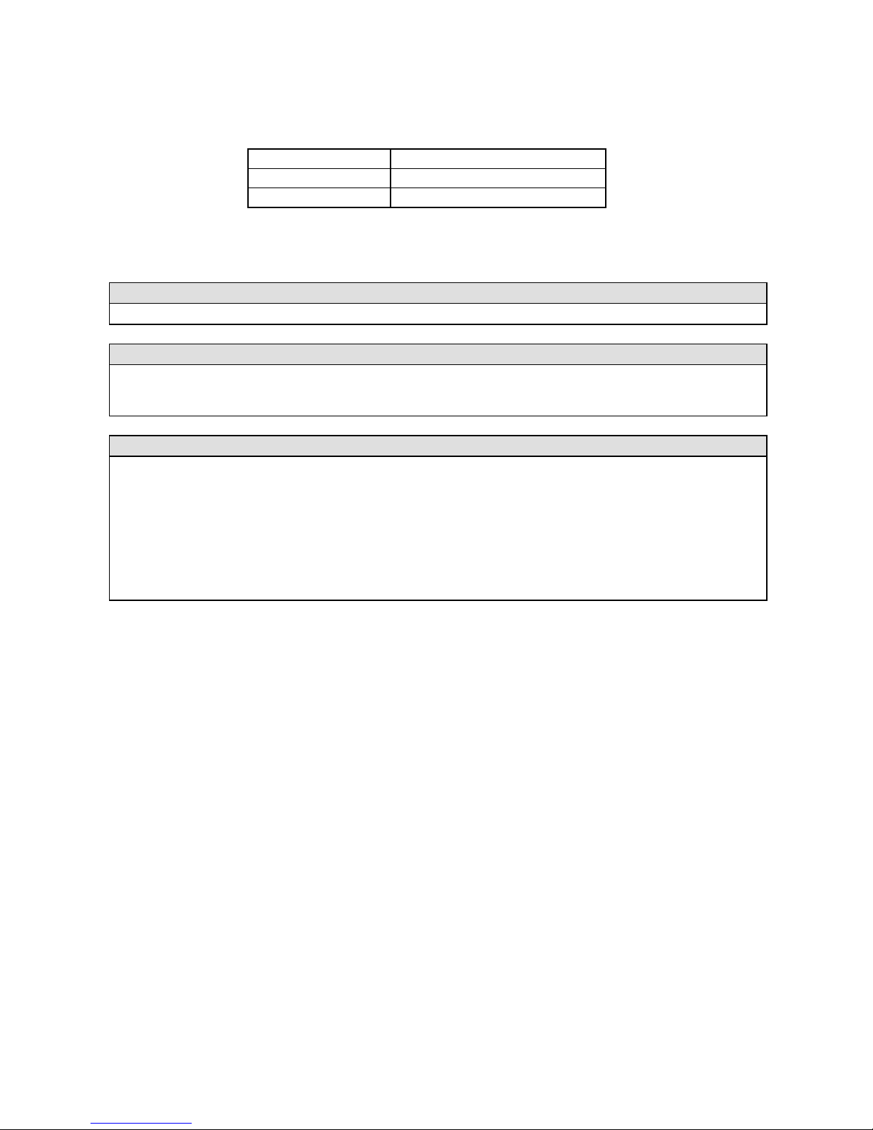
A Ocean-going Superior to 8 Up to 28 m/s Higher than 4 m
B Open sea Up to and including
Force 8
Up to 21m/s Up to and including 4 m
C Inshore Up to and including
Force 6
Up to 17 m/s Up to and including 2 m
D Sheltered waters Up to and including
Force 4
Up to 13 m/s Up to and including 0.5 m
ENGLISH Date: 2009.09.29 Page 9 / 79 Dufour 40 Performance
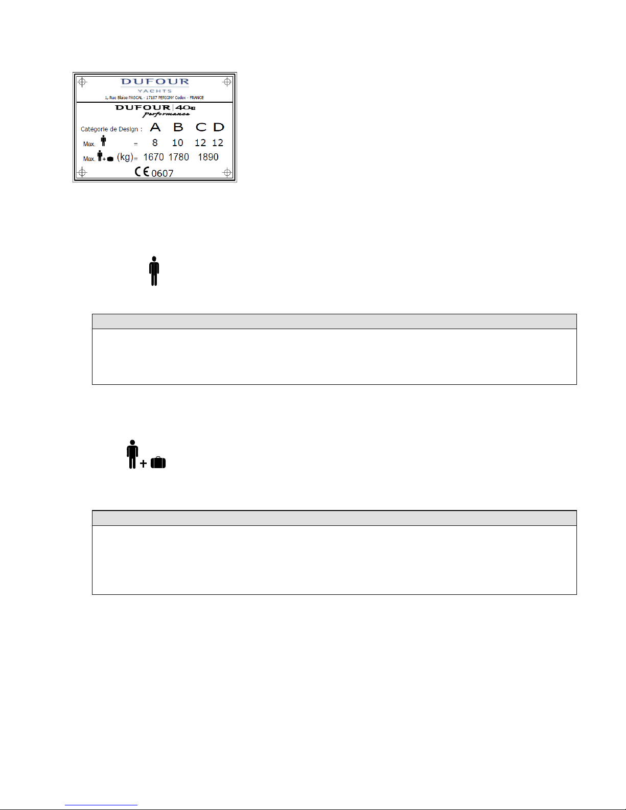
Builder's plate
Design category = A : Ocean-going (see 1.1)
Max. number of people = 8
WARNING
Do not exceed the maximum recommended number of people. However many people there are aboard,
the total weight of the people and equipment must never exceed the maximum recommended loading.
Max. additional loading = 1,670 kg
WARNING
When loading the boat, never exceed the recommended maximum load. Always load the boat carefully
and distribute the weight in a suitable manner in order to maintain the theoretical trim (approximately
horizontal). Avoid placing heavy loads high up.
CE 0607
: Recommended by the builder for navigation in sea
conditions for category for which it was built.
CE mark indicating that the boat complies with all the
requirements of the Directive. The sequence of numbers
is the Certification institution's code. In this case, ICNN
(Institut pour la Certification et la Normalisation dans le
Nautisme), (refer also to: Safety Compliance
Declaration)
: including the maximum number of people with their
equipment, belongings, and supplies. (not including
various tank capacities (water, diesel fuel, ...) and the
loading that may arise from fitting various boatyard
options.
Part of this information is given on the builder’s plate
attached in the cockpit. A full explanation of this
information is given in the chapter that follows.

ENGLISH Date: 2009.09.29 Page 10 / 79 Dufour 40 Performance
Degrees of danger
DANGER
Indicates an extreme intrinsic risk that presents a high probabililty of death or
permanent injury if proper precautions are not taken.
WARNING
Indicates an extreme intrinsic risk that presents a high probabililty of death or
permanent injury if proper precautions are not taken.
NOTE
Indicates a reminder about safety-related practices, or points out dangerous
practices that could result in personal injury or damage to the boat or its
components.
IIII.
.
PPRRIINNCCIIPPAALL SSPPEECCIIFFIICCAATTIIOONNS
S
Model:
DUFOUR 40 Performance
Designer: Umberto Felci & Patrick Roséo
Interior design ROSEODESIGN
Design category A
Notified body no. CE/0607
Engine #
LOA: 12.35 m
Hull length: 11.99 m
LWL: 10.76 m
Maximum beam: 3.90 m
Draught:
- standard ballast
- optional ballast
2.1m
1.76 m
Mast clearance (under lightly loaded conditions): 18.50 m
Ballast weight:
- standard (cast-iron)
- Long (mixed)
- Short (cast-iron):
2,386 kg
2,340 kg
2,442 kg
Light displacement:
- standard ballast
7,950 kg
Standard mainsail area (approximate) 45.00 m²
Light genoa (140%) area (approx) 43.00 m²
Spinnaker area (approx.) 116.0 m²
Water capacity excluding water-heater (approximate) 360 L
Diesel capacity (approximate) 200 L
Holding tank (standard + optional) 50 L + 45 L (optional)
Engine battery 100 Ah
Standard auxiliary battery 100 Ah (+1 x 100 Ah as an optional
extra)
Primary means of propulsion Sail
Maximum permissible on-board engine power 41 kW
Total weight of liquids (all tanks full) 560 L
Nota bene: due to the trim and loading of the boat, is it not usually possible to use the whole of the
various tank capacities for fresh water and diesel. You are recommended to maintain a diesel
reserve of 20%.

ENGLISH Date: 2009.09.29 Page 11 / 79 Dufour 40 Performance
IIIIII.. EELLEECCTTRRIICCAALL SSYYSSTTEEMMSS
Safety and operating instructions for the electrical system (ISO 10133)
WARNING
Improper use of the DC and/or AC systems may give rise to fire or explosion hazards.
Improper use of the AC systems may give rise to electric shock hazards.
Always:
- Check the condition of the batteries (charge and electrolyte level) and the charging system
before putting to sea.
- Disconnect and remove batteries for wintering.
- Do not let battery voltage drop below 10.5 V during wintering.
- Carry spare lamps for all navigation lights and
interior lighting. Respect power ratings, particularly for navigation lights.
- Check operation of the navigational instruments.
- Check operation of navigation lights before night sailings
Never:
- Work on an electrical installation that is live.
- Make any modification to an installation and the relevant diagrams, unless it is carried out by
an electrician qualified in marine electrics.
- Change or modify the breaking capacity of overload protection devices.
- Replace electrical apparatus or equipment with units exceeding
the rated capacity without uprating wiring and protection.
- Leave the boat unattended when the electrical installation is powered, with the exception when
applicable of the automatic bilge pump and the fire or theft protection circuits.
If a fuse or circuit-breaker blows continually, you should consult a specialist to determine the cause of
the short-circuit.
Installing new equipment
Since 1 January 1996, electrical equipment is subject to the European “electromagnetic compatibility”
directive (Ref 89/336/CEE). So new equipment being installed must meet this standard and bear the CE
mark. Equipment must also be supplied with a compliance certificate and instructions for use.
In the case of 220 or 110 V installations, use only double-insulated or earthed equipment. When such
equipment is being installed, respect the fitting instructions (conductor size, protection).
To avoid maintenance problems, be sure to mark in the manual any modifications that may be made to
the electrical circuit diagram.

ENGLISH Date: 2009.09.29 Page 12 / 79 Dufour 40 Performance
Batteries
The battery system comprises one 100 Ah auxiliary battery in the technical area between the aft berths
(two additional 100 Ah batteries available as an optional extra) and one 100 Ah engine starting battery
in the engine compartment.
Their capacities have been designed to handle the power requirements of the on-board accessories. To
avoid any problems, it is necessary to keep a close eye on the maintenance and correct charging of the
batteries.
NOTE
When installing new electrical appliances, take care that the overall consumption
of these appliances remains within the capacity of your batteries.
Always disconnect the negative (-) battery terminal before the positive (+) terminal.
Never allow a conductive object (tools, etc.) to bridge across the two battery terminals.
When handling batteries, keep them horizontal to avoid spillage of electrolyte. Wear gloves and
protective clothing that will prevent any risk of contact with electrolyte in the event of a leak.
In the event of electrolyte splashes, rinse the affected part of the body copiously and consult a doctor.
Electric windlass
NOTE
It is essential to run the engine with the throttle slightly open when using the electric windlass.
220 / 110 Volt installation
DANGER
The on-board 220 V installation is protected by a circuit breaker and fitted with a residual current
device. The wiring of additional 220 V on-board accessories must be carried out by professionals, and
the master circuit-breaker uprated if necessary.
- Disconnect the boat’s power supply when system is not in use.
- Connect the metal cases or housings of installed electrical equipment to the ship’s protective
conductor (green or green / yellow wire).
- Use double-insulated or earthed electrical appliances.

ENGLISH Date: 2009.09.29 Page 13 / 79 Dufour 40 Performance
DANGER
Your boat is delivered without a supply cable or shore connection plug. The cable used must be
designed for exterior use. Its cross-sectional area must be appropriate for its length and the rating
of the main circuit-breaker (see electrical diagram). The plug must be suitable for the socket on the
shore (if necessary, seek the advice of a professional). It should be as close as possible to the IP 67
/ IEC529 type
In order to minimize the risk of electric shock or fire:
- Switch off the shore supply at the on-board isolator before connecting or disconnecting
the shore/boat supply cable.
- Connect the shore/boat supply cable at the boat end before connecting it to the shore
outlet
- Disconnect the shore/boat supply cable at the shore outlet before dis-connect-ing it at the
boat end
- Close the shore outlet cover properly
- Do not make modifications to the shore supply cable; use only compatible connectors.
Never:
- - Go swimming close to a boat connected to a shore supply socket: danger of
electrocution!
Warning! When the boat is moored at the quayside, set the isolator to the ‘off’ position.
Location of the 220 V master circuit-breaker: by the chart table.
During haul-out maintenance, set to the ‘on’ position in order to have earth [grounding] protection
via the shore socket.
WARNING
Never let the end of a ship/shore supply cable dangle into the water. It may create an electrical
field that could injure or kill nearby swimmers.
ENGLISH Date: 2009.09.29 Page 14 / 79 Dufour 40 Performance
IIVV.. GGAASS IINNSSTTAALLLLAATTIIOONN
Operating advice
- Read carefully all instructions for cooker and regulator before use or maintenance.
- Ensure that the gas cylinder and regulator are in accordance with the requirements of the cooker
(flow rate, pressure, type of gas) and with the regulations in force in the country where it is being
used.
- Make sure the appliance gas taps are closed before opening the valve on the cylinder.
WARNING
Fuel-burning naked-flame appliances use up the oxygen in the cabin and release combustion products
inside the vessel. Proper ventilation is necessary: open the designated vents while these appliances are
being used.
Never block the ventilation openings and check that appliances with flues are working properly.
- Do not use the stove as a means of heating.
- Do not obstruct quick access to the elements of the gas installation (cylinder locker, shut-off valve).
- The gas cylinder must always be stowed in the sealed, ventilated space provided. The same applies
to spare or empty cylinders. No other equipment must be stowed in this space.
- Never leave the boat unattended when gas appliances are on.
- Close all valves in the circuit when the boat is left empty (shut-off valve, regulator valve), even if
the cylinder is believed to be empty.
- After the boat has been shut up, never smoke when going below, and ensure that there is no smell
of gas.
- If you smell gas, close the circuit valves and the cooker taps, ventilate the boat, and find the leak
before using the installation again.
WARNING
In the event of an emergency, the circuit valves must be closed immediately.
SAFETY PRECAUTIONS
Certain precautions must be taken to avoid any contact with naked flames or other hot areas.
ENGLISH Date: 2009.09.29 Page 15 / 79 Dufour 40 Performance
Checking the system
- The gas system must be tested periodically:
° Close all the cooker taps.
° Open the cooker supply and regulator valves.
° Check that all connections are gas-tight using a leak detector or by applying soapy water.
ATTENTION!
Do not use solutions containing ammonia.
DANGER!
Never use a flame to look for leaks.
Repairs and modifications to the system should be carried out by a qualified person.
Flexible hoses must be:
- Checked regularly, at least once a year,
- Replaced if the expiry date marked on the hose is passed,
- Replaced five years after the date of manufacture that may be marked on them,
- Replaced in the event of damage.
Changing the gas cylinder
DANGER!
Close the cooker taps and those before the cooker.
Do not smoke nor use a naked light during replacement of the gas cylinder.
WARNING!
In the case of an LPG installation:
- refrain from smoking or using a naked flame while LPG cylinders are being changed
- close the valve on the empty cylinder before disconnecting it to change.
ENGLISH Date: 2009.09.29 Page 16 / 79 Dufour 40 Performance
VV.. DDRRAAIINN && SSAANNIITTAATTIIOONN SSYYSSTTEEMM
Specifications of the drain system
Pump type Theoretical flow rate
Manual 40.5 L @ 45 strokes/minute
Electric 12V 1,920 L / h
Read carefully the operating and maintenance instructions for the bilge pump that goes with your
boat.
ATTENTION!
The level of the water in the bilge must be kept to a minimum.
WARNING!
The bilge pump system is not designed to handle water entering as a result of holing of the hull. It is
intended to remove water coming from spray, leaks from seacocks or other moderate leaks.
SAFETY PRECAUTION
Ensure that bilge pumps are in working order before putting to sea
Know where to find the hand pump and its handle
Know where to find the switch for the electric pump on the electrical panel
Regularly clean away any debris that might obstruct the sump well and the pump intake points or
strainers.
If the watertight bulkheads that isolate the fore- and after-peaks are fitted with valves, these should
normally be kept closed and only opened in order to drain the water into the main bilge
Pressurized fresh-water pump
Fresh water is supplied to the sink and washbasin(s) by an electric water pump beneath port
banquette in saloon. A filter is installed upstream of the pump, and must be cleaned regularly.
Never allow the pump to run if the tank is empty. Refill the tank before using the water supply
again.
The tanks can be sterilized using Clonazone® tablets (available from pharmacies). Every year,
remove the inspection covers and clean them by filling with water containing a bactericidal
detergent; leave it to act for a few hours, then rinse two or three times. During wintering, fill the
tanks up completely to avoid the development of algæ or bacteria, or if there is a risk of freezing,
empty the tanks; never use anti-freeze.
Hot water is produced by a water-heater connected to the engine cooling circuit and the shore
electric supply.
After the water-heater has been emptied, make sure that the element is covered before power is reapplied.
ENGLISH Date: 2009.09.29 Page 17 / 79 Dufour 40 Performance
Seacocks
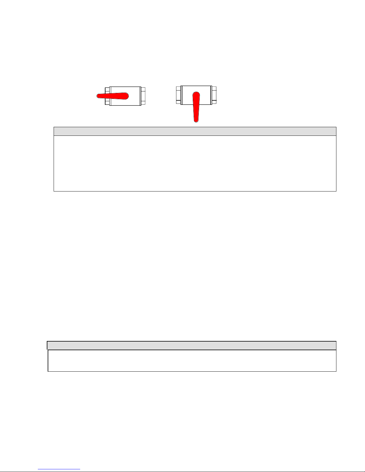
Seacocks are of the ¼-turn type:
- OPEN position: handle in line with seacock body,
- CLOSED position: handle perpendicular to seacock body.
ATTENTION!
Never interfere with the tightening of the seacocks to the hull. In the event of a leak, consult a
professional.
In bad weather or when leaving your boat, close all the sanitation system seacocks.
Keep seacocks closed when not being used.
During wintering, clean and rinse the seacocks and skin fittings. Inspect the
brass accessories; slight surface corrosion is normal.
In the event of more serious corrosion, consult your agent.
Operation of the sea toilets
- Open the sea-water inlet seacock.
- Open the bowl emptying seacock.
- Set the lever to the “FLUSH” position.
- Operate the pump.
- To empty the bowl and avoid any water slopping when heeling, set the lever to the “DRY BOWL”
position.
- Operate the pump until the bowl is dry.
- Repeat these flushing / emptying operations as many times as is necessary to ensure complete emptying
of the pipes.
When toilets are not being used, set the lever to the «DRY BOWL» position, or the «CLEF» position for
certain models.
- Close seacocks after use, as the toilet is below the waterline.
- Change the toilet seals regularly.
Holding tank operation
WARNING!
Where a HOLDING TANK is fitted, take care to lock the valve into the EVACUATION TANK position,
to avoid any accidental discharge during wintering
- The sewage tank(s) (50 l + optional extra 45 l) operate using the toilet hand pump.
- The contents of the toilet pan are discharged straight into the holding tank;
- Periodically check that the vent is working properly.
- A deck plate is provided for emptying the tank
- The discharge valve can be sealed in the closed position.
- Once a season, arrange to clean out the tank using a biodegradable disinfectant chemical. Leave the
system empty if the vessel is to be left in below-freezing temperatures
Vanne ouverte
Vanne fermée
OPEN position
CLOSED position

ENGLISH Date: 2009.09.29 Page 18 / 79 Dufour 40 Performance
VVII.. FFLLOOOODDIINNGG
Boat flooding risks:
- Before putting to sea, always check that portholes, deck hatches and any other openings that
could allow flooding are shut.
- When under sail, close all seacocks, except the engine water intake.
- Periodically check:
- Skin fittings, seacocks and pipes are watertight
- Proper emptying of the cockpit drains.
- The watertightness of the stern gland (in the case of an IB engine).
WARNING!
Cockpit locker lids must be fastened shut before putting to sea. This is particularly important for those
lockers that represent a major flooding risk
VVIIII.. FFIIRREE PPRROOTTEECCTTIIOONN
Installation
- Fire-extinguishers are subject to national regulations, and for this reason they are not supplied
with your boat.
- We recommend you to equip your boat with fire extinguishers meeting the ISO 9094-1
standard, with the following specifications:
a) Minimum capacity per extinguisher: 5A/34B(*)
b) Minimum combined extinguisher capacity: 10A/68B(*)
(*) As per the ISO/WD 9094-2 standards
c) 1 extinguisher within:
- 1 m (for boats < 10 m) or 2 m (for boats > 10 m) of the cockpit
- 2 m of the extinguisher opening for dowsing the engine,
d) 1 extinguisher within 2 m of the cooker,
e) 1 extinguisher within 5 m of the bunks.
f) CO2 extinguishers may be placed in accommodation areas only where flammable liquids are
present (e.g. galley) or where there is powered electrical equipment. There must not be more
than one CO2 extinguisher per area at risk, and its maximum capacity must not exceed 2 kg.
Only compatible replacement parts must be used in fire protection systems. They must bear the
same markings and be technically equivalent.
In addition, a fire blanket should be stored close to the galley — very useful particularly in the
event of a pan fire involving oil.

ENGLISH Date: 2009.09.29 Page 19 / 79 Dufour 40 Performance
WARNING
If a CO2 extinguisher is fitted, the following information must be displayed close to its location:
“This extinguisher contains CO2 - use only on electrical or cooker fires. To avoid suffocation after
discharging, leave the area immediately. Ventilate before re-entering.”
Do not open the engine compartment immediately after putting out a fire, to avoid the release of toxic
smoke or spraying of burning materials (oil, water).
Safety instructions
NOTE
It is the responsibility of the owner / skipper to:
- Have fire-fighting equipment checked in accordance with the stipulations of the builder and the
regulations in your country.
- Replace fire-fighting equipment if it has expired or been discharged, by extinguishers of equal or
greater capacity.
- Show members of the crew:
• The location and operation of fire-fighting equipment
• The location of the engine compartment extinguishing hole (located on the
companionway).
- Ensure that fire-fighting equipment is readily accessible whenever the boat is occupied.
Never:
- modify any of the boat’s installations (especially the electrical, fuel or gas installations) or
allow any unqualified person to modify these installations.
- Obstruct gangways to emergency exits (deck hatches)
- Obstruct safety controls (gas valves, fuel valves, electrical switches).
- Obstruct fire extinguisher stowages.
- Leave the boat unattended with a cooker or heater alight.
- Use a gas lamp in the boat
- Fill a fuel tank or change a gas cylinder while the engine is running, or the cooker or heater are
alight.
- Smoke while handling fuel or gas.
- Fit free-hanging curtains near the cooker or any other appliance using a naked flame.
- Store flammable products in the engine compartment.
Always keep the bilges clean and check that there is no fuel vapor or gas.
ENGLISH Date: 2009.09.29 Page 20 / 79 Dufour 40 Performance
VVIIIIII.. EENNGGIINNEE
Regular maintenance must be carried out in accordance with the engine manufacturer’s
recommendations. Read care-fully the engine operating instructions that come with the boat. Do not
hesitate to consult your agent or a qualified professional.
In particular, follow the instructions for wintering.
General precautions
NOTE
Do not use sail and engine if the heel angle is more than 10°
Any engine change must respect the capacities of the boat and be performed by an engineer
specializing in marine mechanics.
NOTE
After first launching and tensioning of rigging, check the alignment of the propeller shaft or the saildrive flange ring.
Ensure that the cooling circuit water intake seacock is open, and that water is coming out of the
engine exhaust.
Boats fitted with rotating seal stern gland: bleed the air from the gland after each launch.
On subsequent launches, a brief check of propeller fixing can be made. Incorrect operation of the
folding propeller will lead to vibration
Regularly check the condition of the anodes and ensure that they are suitable for the boat’s
environment (fresh water, salt water). Change the anodes every year.
The role of the sacrificial anodes is to balance the potential that appears between the aluminium and the
various metals (stainless, bronze, etc.). The 3 anodes have an average life of 1–2 years.
These anodes are made of zinc. It is essential not to use magnesium ones. Impressed current cathodic
protection systems should not be used
If the anodes are not eroded, you need to check:
- that they have not been painted over,
- that they are correctly fixed and in contact with the hull,
- and that they are indeed made of zinc
Exhaust gas emission
DANGER!
Internal combustion engines produce carbon monoxide. Prolonged exposure to exhaust gasses can have
serious consequences, and may even cause death.
Safety
DANGER!
In order to avoid all risk of serious injury from the propeller, the engine must not be started when there
are people swimming near the boat.
Whenever possible, the engine must be stopped for any engine maintenance or checking operations. If
this is impossible, then particular care must be taken with moving parts (belts, shafts, etc.) to avoid any
danger of injury.

ENGLISH Date: 2009.09.29 Page 21 / 79 Dufour 40 Performance
Wintering
Read carefully the operating and maintenance instructions for the engine that goes with your boat and
the instructions for wintering.
In the absence of other instructions, proceed as follows:
- Close the engine water intake seacock,
- Disconnect the pipe from the engine water intake seacock,
- Drain the sea-water circuit,
- Place the pipe into a drum of –25° anti-freeze coolant,
- Run the engine until the fluid comes out of the exhaust,
- At the end of this operation, re-connect the pipe to the seacock,
- Attach a notice to the electrical panel and the battery isolator to the effect that the engine
water intake seacock is closed.
IIXX.. FFUUEELL IINNSSTTAALLLLAATTIIOONN
In the event of deterioration, flexible fuel pipes must be replaced by pipes bearing the same markings.
ATTENTION!
Depending on the trim and loading of your boat, the whole of the nominal fuel capacity may not be
usable. Always maintain a 20% reserve for safety.
Avoid contact between flammable materials and hot parts of the engine.
Never:
- Store flammable materials in unventilated spaces.
- Smoke while filling tanks.
- Obstruct ventilation openings (vents, engine ventilation grilles).
- Modify the installation, unless this is carried out by a technician qualified in this field.
XX.. SSTTEEEERRIINNGG SSYYSSTTEEMM
The steering system plays a vital role in the safety and comfort of your boat.
Helm
The DUFOUR 40 is fitted, as standard, with an emergency tiller and, as option, with a dual wheel with
a system of rudder cables and chains
Checks to be carried out periodically: Check the play in the various elements (rudder stock/bearings,
tension and wear in mechanical components) and grease the sprocket and chain if necessary.
In the event of any doubt or problem, consult your agent.

ENGLISH Date: 2009.09.29 Page 22 / 79 Dufour 40 Performance
Emergency tiller
NOTE
The DUFOUR 40 is provided with an emergency tiller that must be kept readily accessible — we
recommend it should be stowed in the cockpit locker close to the deck-plate for it.
It is only designed for sailing at reduced speed in the event of damage to the helm.
To use it:
- Unscrew the deck-plate to reveal the head of the rudder stock
- Fit the tiller onto the head of the rudder stock.
XXII.. SSAAIILLIINNGG
WARNING
In all situations, make sure you adapt the speed of your boat to the surrounding conditions, and
always maintain a margin for safety. Pay particular attention to:
- Other boat movements
- Manœuvres in port
- When passing through mooring areas.
- The state of the sea, currents, the strength of the wind. Breaking waves represent a
significant threat to stability;
When at sea, carefully attach any movable items aboard.
Obey the rules of priority as set out in the Rules of the Road and imposed by COLREG
Ensure you always have sufficient stopping or maneuvering distance if necessary to avoid a collision
Respect speed limit areas.
Out of courtesy and for the safety of other vessels, take care not to create excessive wash close to
other craft.
In all cases, make sure you keep regularly up to date with local rules, as well as the international
regulations.
WARNING
You should fit your boat with life-lines. Anchor-points are provided on the deck. Please refer to the
deck fittings plan for your boat.
Your boat’s stability has been designed to take into account the boat builder’s catalogue options.
Any alteration to on-board weight distribution (for example: adding a radar, changing an engine,
etc.) can have an appreciable effect on your boat’s stability, trim, and performance.
Towing a boat creates significant overloading, reducing the stability of your boat.
For the same reason of reduced stability, never:
- use the boom or davits to lift heavy loads.

ENGLISH Date: 2009.09.29 Page 23 / 79 Dufour 40 Performance
XXIIII.. LLIIGGHHTTNNIINNGG PPRROOTTEECCTTIIOONN
Your boat is protected against lightning. The rigging is electrically connected to earth. Nonetheless, for your
safety, it is necessary to respect certain precautions.
Maintenance
If the vessel has been hit by lightning:
- The protection installation must be inspected to detect physical damage and check the integrity
of the device, as well as the continuity of the earthing.
- The compasses, electrical and electronic devices must be examined in order to ascertain if
damage or calibration changes have occurred.
Protection of persons during a storm
WARNING
During a thunderstorm, it is preferable to obey the following instructions:
- People should stay below as far as possible.
- People should stay out of the water and not let their arms or legs hang into the water.
- Whilst maintaining satisfactory control of the boat and its sailing, people should not touch any part
connected to a lightning protection installation, especially not in such a way as to form a link between such
parts.
- It is desirable that people should avoid any contact with metal parts of the rigging, the spars, deck fittings
and the lifelines.
XXIIIIII.. EENNVVIIRROONNMMEENNTTAALL PPRROOTTEECCTTIIOONN && SSAAFFEETTYY
We recommend you to find out about local regulations concerning respect for the environment, and to obey
international regulations against pollution in the marine environment (MARPOL), together with the codes of
good practice.
ATTENTION!
Most cleaning products, engine oils and hydrocarbons are likely to affect
the environment, so they should be discharged in authorized locations (check with the
Harbour Master's office).
Certain chemical products may also represent a risk for your own and other people’s safety, which is
why it is important to read and obey the instructions for use.
Substances used must be labeled and stored in an appropriate, ventilated place in the boat.
ENGLISH Date: 2009.09.29 Page 24 / 79 Dufour 40 Performance
XXIIVV.. SSAAFFEETTYY FFAACCIILLIITTIIEESS
There is no harmonization of mandatory safety equipment across the European Community. You should find
out about current national requirements for CE-marked vessels.
In France, the skipper is responsible for ensuring that recreational craft bearing the CE mark carry aboard the
mandatory handling and safety equipment stipulated for the relevant sailing category.
Your boat is provided with a stowage position for a life-raft, read the life-raft instruction manual carefully.
The crew must be made familiar with the use of all the safety equipment (harnesses, flares, life-raft, etc.).
Sailing schools and clubs regularly organize training sessions.
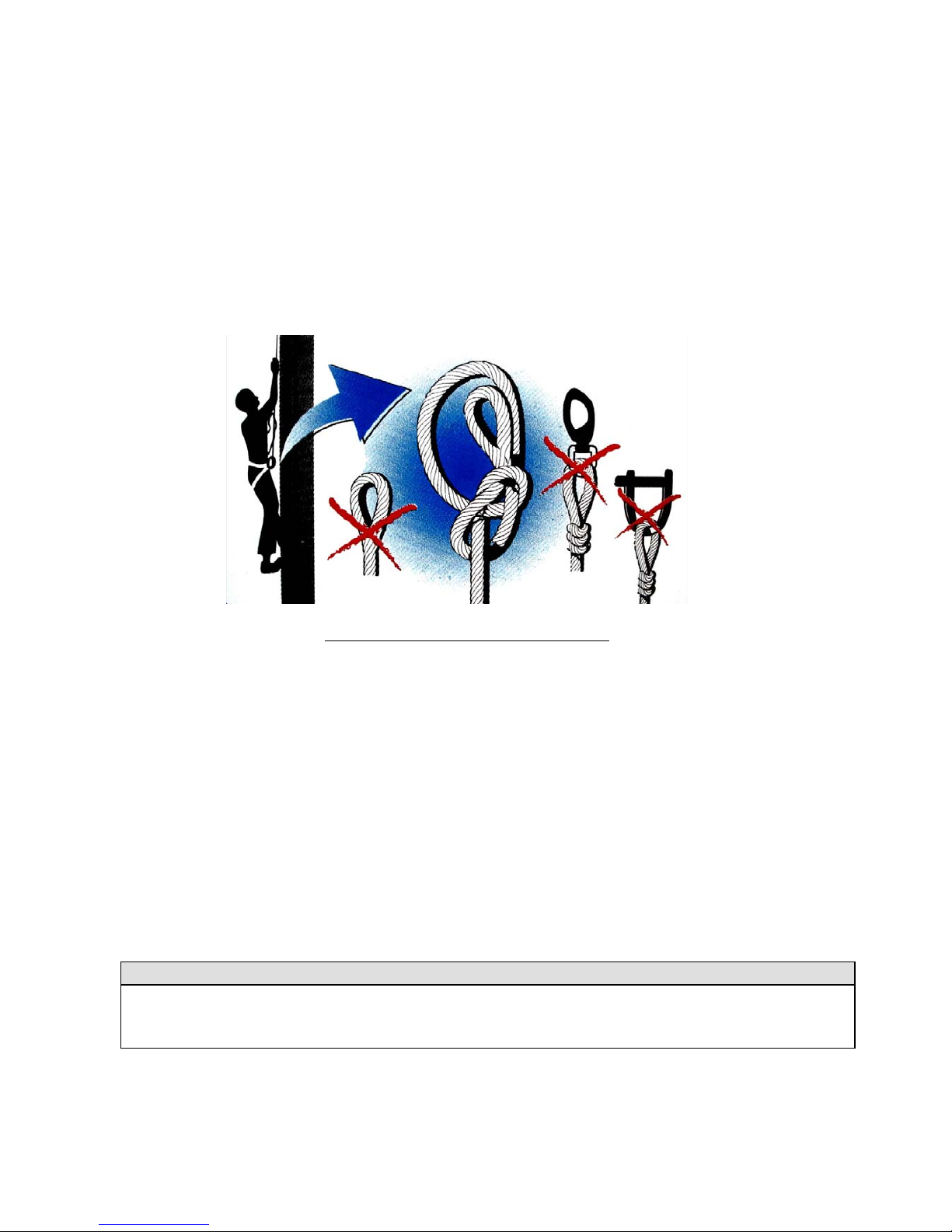
Advice for hoisting a person up the mast
XXVV.. HHAANNDDLLIINNGG,, TTRRAANNSSPPOORRTTIINNGG,, HHAAUULLOOUUTT
When craning, take care that the slings are correctly positioned and are not fouling the propeller, the saildrive or a fragile transducer.
Lifting frames must be wide enough, or fitted with spreaders, so as to avoid applying excessive lateral
pressure on the rubbing strakes.
Avoid allowing slings to foul the life-lines. During transport or haulout, the keel should be in proper contact
with its support and should be taking most of the boat’s weight.
Cradle pads must be positioned against structural elements and exert only the pressure necessary for the boat
to be properly balanced.
Take advantage of the opportunity provided by haul-outs to inspect the propeller, rudder, skin fittings, and
transducers.
ATTENTION!
Aft lifting point is located near the sail-drive
 Loading...