

Dufour Yachts 360 Grand Large Owner's Manual
OWNER'S MANUAL
YACHT DESIGN CATEGORY: A
ENGLISH 29/01/2018 1/86 DUFOUR 360 Grand Large
IN ACCORDANCE WITH EUROPEAN DIRECTIVE 2013/53/UE

This page intentionally left blank.
This page intentionally left blank.
This page intentionally left blank.
ENGLISH 29/01/2018 2/86 DUFOUR 360 Grand Large

Your agent:
Name
Manual
I, the undersigned:
Name
Address
owner of DUFOUR 360 no.
confirm that I have received the DUFOUR 360 Owner's Manual and accept its being written in the
Dated:
Signature:
Detach along dotted line
…………………………………………………………………………………………………………………
11, Rue Blaise Pascal- 17187 PERIGNY CEDEX- FRANCE
I, the undersigned:
Name
Address
owner of DUFOUR 360 no.
confirm that I have received the DUFOUR 360 Owner's Manual and accept its being written in the
Dated:
Signature:
is the DUFOUR YACHTS’ representative and will give you all the help you need to solve any
difficulties you might have during the launching and masting of your boat, as well as for
commissioning and maintenance technical checks. If necessary, he will help you with the
administrative process of registering your boat.
As soon as you become the owner, familiarize yourself with the manual supplied with your boat,
sign and date the receipt acknowledgements below, and give (or send) the last one to your agent.
Acknowledgement of receipt of the Owner's Manual. Owner's copy to be kept in your
English language.
Owner's Manual receipt acknowledgment to be returned to DUFOUR YACHTS
English language.
ENGLISH 29/01/2018 3/86 DUFOUR 360 Grand Large

This page intentionally left blank.
This page intentionally left blank.
This page intentionally left blank.
ENGLISH 29/01/2018 4/86 DUFOUR 360 Grand Large

CONTENTS
Seacocks
Operation of the sea toilets
Holding tank operation (ISO 8099:2000)
INTRODUCTION
I.
GENERAL INFORMATION
YACHT DESIGN CATEGORY: ________________________________________________________________ 9
Certification _____________________________________________________________________________ 9
Identification _____________________________________________________________________________ 9
Builder's plate __________________________________________________________________________ 10
Degrees of danger _______________________________________________________________________ 10
II. PRINCIPAL SPECIFICATIONS
III. ELECTRICAL SYSTEMS
Safety and operating instructions for the electrical system _________________________________ 13
Fitting new equipment ___________________________________________________________________ 13
Batteries _______________________________________________________________________________ 14
Electric windlass_ _______________________________________________________________________ 14
Ins 220/110 volt installation (ISO 13297:2000) ___________________________________________ 15
......................................................................................................................................................... 8
............................................................................................................................. 9
................................................................................................................... 11
.................................................................................................................................... 13
IV. GAS INSTALLATION
General information _____________________________________________________________________ 16
V. DRAIN & SANITATION SYSTEM
Drainage system characteristics (ISO 15083:2003) _________________________________________ 18
Pressurized fresh-water pump ___________________________________________________________ 18
_______________________________________________________________________________ 19
VI. FLOODING
........................................................................................................................................................... 20
VII. FIRE PROTECTION
Installation _____________________________________________________________________________ 20
Safety instructions ______________________________________________________________________ 21
VIII. ENGINE
General precautions _______________________________________________________________________ 22
............................................................................................................................................................. 22
......................................................................................................................................... 16
...................................................................................................................... 18
_______________________________________________________________ 19
____________________________________________________ 19
.......................................................................................................................................... 20
Exhaust gas emission ____________________________________________________________________ 22
Safety 22
Wintering _______________________________________________________________________________ 23
IX. FUEL INSTALLATION
X. HELM SYSTEM
Tiller 23
Emergency tiller ________________________________________________________________________ 24
ENGLISH 29/01/2018 5/86 DUFOUR 360 Grand Large
.................................................................................................................................................... 23
....................................................................................................................................... 23

XI. SAILING
............................................................................................................................................................... 24
XII. FALL PREVENTION AND MEANS OF GETTING BACK ABOARD
............................................................ 25
XIII. LIGHTNING PROTECTION
Maintenance ____________________________________________________________________________ 25
Protection of people during a thunderstorm _______________________________________________ 26
XIV. ENVIRONMENTAL PROTECTION & SAFETY
XV. SAFETY FACILITIES
XVI. HANDLING, TRANSPORTING, HAULOUT
XVII. MOORING, ANCHORING, AND TOWING
Responsibility ___________________________________________________________________________ 28
XVIII. GUARANTEE, TRANSFER OF OWNERSHIP
1. Presentation plan
2. Accommodation layout
............................................................................................................................. 25
............................................................................................. 26
......................................................................................................................................... 27
.................................................................................................. 27
.................................................................................................... 28
............................................................................................ 29
........................................................................................................................................ 34
............................................................................................................................... 35
3. Deck fittings plan
4. Sail plan
......................................................................................................................................................... 39
......................................................................................................................................... 37
5. Halyard and sheet operating diagram
6. 220V circuit diagram
................................................................................................................................... 47
7. Charging and power system diagram
8. 12V electric panel
9. 12 V terminal diagram
10. 12V electrical installation diagram
11- 220V electrical installation diagram
12- Fuse location diagram
13 - Steering system diagram
14
-
Gas system diagram
........................................................................................................................................ 51
................................................................................................................................ 53
......................................................................................................... 55
.......................................................................................................... 58
................................................................................................................................ 61
........................................................................................................................ 63
................................................................................................................................. 65
.................................................................................................... 41
..................................................................................................... 49
15- Abandon ship plan
16- Fresh-water system diagram
17 - Drain system diagram
18 - Skin fitting location diagram
19 Mechanical installation diagram
20 Gas system diagram
ENGLISH 29/01/2018 6/86 DUFOUR 360 Grand Large
....................................................................................................................................... 67
................................................................................................................... 69
............................................................................................................................. 71
................................................................................................................. 73
............................................................................................................. 76
................................................................................................................................... 78

21 Holding tank installation diagram
........................................................................................................... 80
22 Lifting diagram
............................................................................................................................................. 82
ENGLISH 29/01/2018 7/86 DUFOUR 360 Grand Large

INTRODUCTION
DUFOUR YACHTS is pleased to present you with this Manual which will help you get to know your boat
better.
This Manual has been produced to help you use your boat safely and enjoyably. It contains details of the
boat, the equipment supplied or fitted, its systems and information about their use. Read it car efully and
familiarize yourself with the boat before using it.
This Owner’s Manual is not a course in sailing safety or seamanship. If this is your first boat or you are
changing to a type of boat you are unfamiliar with, for your convenience and safety, make sure you gain
experience in handling and using it before taking command. Your agent, national sailing or cruising
federation or yacht club will be happy to give you information about sailing schools or qualified instr uctors
in your area.
Ensure that forecast wind and sea conditions correspond to the design category of your boat, and that you
and your crew are capable of handling the boat in these conditions. Even when your boat is suitable f or
them, the sea and wind conditions corresponding to design categories A, B, and C vary from severe storm
for category A to severe conditions for the top end of category C, subject to dangers of abnormal gusts or
waves; these are dangerous conditions in which only an experienced, trained crew in good shape, sailing a
properly-maintained boat, can sail in a satisfactory manner.
This Owner's Manual is not a detailed maintenance or repair guide. In the event of problems, consult the
boatbuilder or their representative. If a maintenance manual is provided, be sure to use it.
Always employ the services of an experienced professional for maintenance, fitting accessories, or
modifications. Modifications that could affect the characteristics of the boat must be assessed, performed
and documented by qualified personnel. The boatbuilder cannot be held responsible for modifications
made without their approval.
In certain countries, a skipper's license or some form of authorization is required, or special rules and
regulations are applicable.
Always maintain your boat correctly and make allowances for deterioration due to age or resulting, where
applicable, from heavy or unsuitable use. Any boat, however sturdy, can be severely damaged if it is used
incorrectly. This is incompatible with safe sailing. Always adapt the speed of your boat to the surrounding
conditions.
If your boat is equipped with a life-raft, read its instruction manual carefully. The crew must have all the
safety equipment on board (life-jackets, harnesses, etc.), corresponding to the type of boat, weather
conditions, etc. I n some countries, this equipment is mandatory. The crew must be familiar with the use of
all the safety equipment and the emergency safety procedures (man overboard recovery, towing, etc.);
training sessions are regularly organized by sailing schools and clubs.
It is recommended that all persons wear appropriate buoyancy aids (life-jackets, personal flotation devices)
when on deck. It should be noted that in certain countries, it is compulsory to wear a buoyancy aid
(complying with national regulations) at all times.
KEEP THIS MANUAL IN A SAFE PLACE AND PASS IT ON TO THE NEW OWNER IF YOU
SELL THE BOAT.
WARNING: Our boats are regularly improved in light of our customers’ experiences and
research carried out by the shipyard. As a result, the specifications given in this Owner’s
Manual are not contractually binding and may be changed without notice and wi thout any
obligation to update them. This manual is intended to cover as much information a s
possible, so certain equipment or paragraphs might not apply to your boat. In case of
doubt, please refer to the inventory which should have been given to you by your agent
when you placed your order.
ENGLISH 29/01/2018 8/86 DUFOUR 360 Grand Large

I. GENERAL INFORMATION
Effective wave
into account
Up to and including
4 m
Up to and including
2 m
Up to and including
0.5 m
YACHT DESIGN CATEGORY:
Your DUFOUR 360 comes under the OCEAN-GOING design category A.
Under conditions of normal use, your boat is designed to sail in waves with a significant height
exceeding 4 m and winds of force 8 or above on the Beaufort scale, and to withstand the severest
conditions.
This sailing capability is equally dependent on the skills of the crew, their physical capacities, the
maintenance of the boat and its equipment.
So always take care before putting to sea.
DUFOUR YACHTS is not able to guarantee perfect functioning of the boat in exceptional sea
conditions (violent storms, hurricanes, cyclones, waterspouts, etc.)
SUMMARY OF DESIGN CATEGORIES
Design
categories
Wind strength
(Beaufort)
Wind
speed
height to be taken
A Higher than 8 Up to 28 m/s Higher than 4 m
B Up to 8 Up to 21 m/s
C Up to 6 Up to 17 m/s
D Up to 4 Up to 13 m/s
Check weather information before putting to sea: Take to the sea, don’t take risks!
In port: every day, the Harbor Master's Office posts weather bulletins and forecasts for the
next few days .
Météo France on 08 36 68 08 08
Navifax - direct line: +33 (0)8.36.70.18.52.
VHF: CROSS transmits several bulletins per day, preceded by an announcement on
Channel 16.
Certification
DUFOUR YACHTS has chosen the Institut pour la Certification et la Normalisation dans le Nautisme
as the notified body for verifying that your boat complies with European directive CE 2013/53, in
accordance with module B.
Identification
The hull identification number is located on the starboard side of the transom. It contains a series
of letters and numbers that begin with FR-DUF...
ENGLISH 29/01/2018 9/86 DUFOUR 360 Grand Large

Builder's plate
Category A = 6
Category D = 10
: recommended by the builder for navigation in sea
: CE mark indicating that the boat complies with all the
: recommended by the manufacturer including the
weight of all passengers aboard, provisions and
included in the boat’s light displacement, but
excluding the contents of the tanks.
Some of this information is provided on the builder’s
plate attached to the boat. A full expl anati o n o f this
information is given below.
Design category = A : (See 1.1)
Maximum number of people:
Category B = 8
Category C = 10
WARNING
Do not exceed the maximum recommended number of people. However many people there are
aboard, the total weight of the people and equipment must never exceed the maximum
recommended load.
Recommended max. load:
Category A = 1,440 kg
Category B = 1,540 kg
Category C = 1,610 kg
Category D = 1,610 k g
WARNING
When loading the boat, never exceed the recommended maximum load. Always load the boat
carefully and distribute the weight in a suitable manner in order to maintain the theoretical trim
(approximately horizontal). Avoid placing heavy loads high up.
conditions corresponding to the category for which it
was built.
personal belongings, in addition to all equipment not
CE 0607
requirements of the Directive. The sequence of digits is
the code for the Certifying Body. In this case, it is ICNN
(Institut pour la Certification de la Normalisation dans le
Nautisme), (see also: Sa fety Compliance Declaration).
Degrees of danger
DANGER
WARNING
NOTE
ENGLISH 29/01/2018 10/86 DUFOUR 360 Grand Large
Indicates an extreme intrinsic risk that presents a high probability of
death or permanent injury if proper precautions are not taken.
Indicates a risk that presents a high probability of death or permanent
injury if proper precautions are not taken.
Indicates a reminder about safety-relate d pr actices, or points out
dangerous practices that could result in personal injury or damage to
the boat or its components, or to the environment.

Model:
DUFOUR 360
Grand Large
Boatbuilder
Dufour Yachts
FRANCE
Architecture:
Umberto Felci
Interior design
DUFOUR Design
YACHT DESIGN CATEGORY:
A
Notified body no.
CE/0607
Engine #
FR-DUFGXXX8XXXX
Primary means of propulsion
Sail
L
max
LOA (with overhang stemhead)
10.30 m (10.73 m)
LH
Hull length*
9.98 m
B
max
Maximum beam*
3.54 m
BH
Hull beam*
3.54 m
HA
Maximum air draft*
15.00 m
T
max
Draught (deep keel)*
1.90 m
Deep keel weight
1,550 kg
Draft (shallow keel)*
1.55 m
Shallow keel ballast weight
1,650 kg
Standard mainsail area (approximate)
34 m²
Jib area (approximate)
18 m²
Genoa area (approximate)
25 m²
Maximum permissible on-board engine power
30 HP / 20.9 kW
Water capacity excl. 20L (approx.) water heater
200 L (+180 L as option)
Diesel capacity (approximate)
200 L
Holding tank
50 L
Engine battery
75 Ah
Auxiliary battery (1 standard + 1 optional)
75 Ah + (+75 Ah as an
optional extra)
MLC
Light displacement (deep keel)
5,775 kg
MMO
Minimum condition displacement (deep keel)
6,008 kg
ML
Maximum loading
1,780 kg
Total weight of liquids (all tanks full)
333 kg
M
LDC
Displacement with maximum load
7,531 kg
II. PRINCIPAL SPECIFICATIONS
11, Rue Blaise Pascal
17187 Périgny cedex
*The above dimensions comply with ISO 8866, specifically:
L
: maximum length of the vessel including normally fixed parts such as bow rollers,
max
balconies, etc.
LH: maximum length of the vessel including structural elements that are an integral part of the
vessel, and excluding removable parts.
B
: breadth of the vessel measured between the outermost portions and may include
max
detachable parts such as top rails, railings, etc.
B
: vessel width measured between the outermost fixed portions and excluding all removable
H
parts
H
vertical distance between the water plane under light displacement and the highest point of
A:
the mast structure. (this does not take into account equipment such as lights and antennas that
can be attached to the masthead)
ENGLISH 29/01/2018 11/86 DUFOUR 360 Grand Large
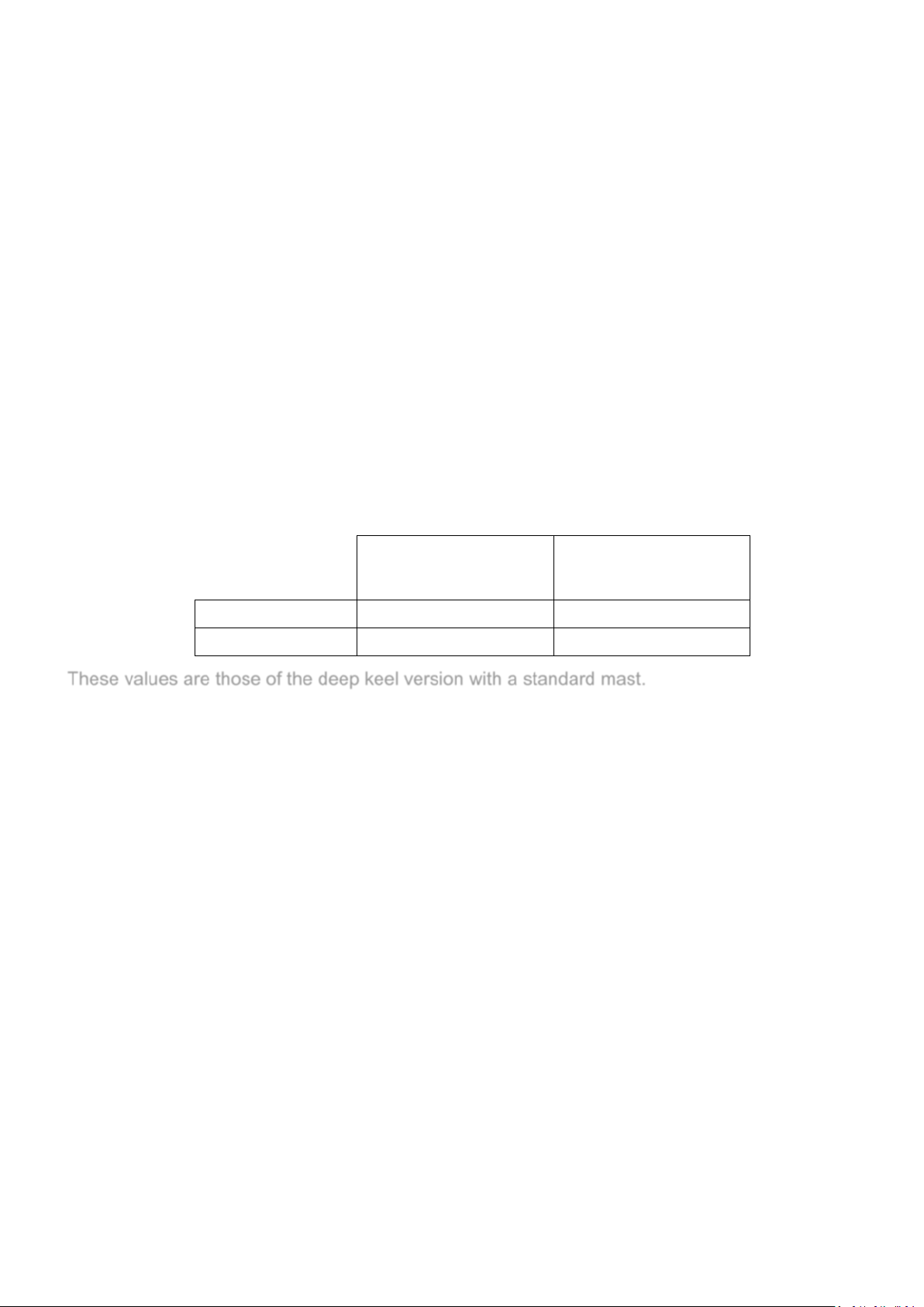
T
Loaded arrival
(Mla)
STIX (deep keel)
34.96
32.30
AVS(deep keel)
127.2°
122.4 °
: the maximum draft is measured at the lowest points of ballast on board the vessel
max
M
: The Maximum Load is the sum of the maximum recommended load plus the total mass of the
L
various liquids (drinkable or not)
Nota bene: due to the trim and loading of the boat, is it not usually possible to use the whole
of the various tank capacities for fresh water and diesel. It is recommended that you
maintain a diesel reserve of 20%.
Specific information
This vessel has been assessed with the help of the Stability Index (STIX), a measure of overall
safety with regard to stability, which takes into account the effects of the length of the vessel, its
displacement, hull proportions, stability characteristics and its resist anc e to fl oodi ng .
The maximum total load is the sum of the maximum recommended load and the total mass of the
various liquids (see ISO 12217-2: 2015)
The second index (AVS, angle of vanishing stability) represents the heel angle at which stability is
lost, in degrees.
Minimum operating
condition (MMO)
condition
These values are those of the deep keel version with a standard mast.
ENGLISH 29/01/2018 12/86 DUFOUR 360 Grand Large

III. ELECTRICAL SYSTEMS
Make any modification to an installation and the relevant diagrams, unless it is carried out by an
Safety and operating instructions for the electrical system
WARNING
Improper use of the DC and/or AC systems may give rise to fire or explosion hazards.
Improper use of the DC and/or AC systems may give rise to fire or explosion hazards.
Always:
● Check the condition of the batteries (charge and electrolyte level) and the charging system
before putting to sea.
● Disconnect and remove batteries for wintering.
● Do not let battery voltage drop below 10.5 V during wintering.
● Carry spare bulbs for all navigation lights and interior lighting. Respect power ratings,
particularly for navigation lights.
● Check operation of the navigational instruments.
● Check operation of the navigation lights before sailing at night.
You must never:
● Work on a live electrical installation.
●
electrician qualified in marine electrical work.
● Change or modify the breaking capacity of overload protection devices.
● Replace electrical apparatus or equipment with units exceeding the rated capacity without
uprating wiring and protection.
● Leave the boat unattended when the electrical installation is powered, with the exception of the
automatic bilge pump and the fire or theft protection circuits when applicable.
If a fuse or circuit-breaker blows repeatedly, you should consult a specialist to determine the cause
of the short-circuit.
Fitting new equipment
Since January 1st 1996, electrical equipment is subject to the European “electromagnetic
compatibility” directive (Ref 89/336/CEE). It is therefore necessary that any new equipment you
may wish to install meets the requirements of this standard and bears the CE mark. Equipment
must also be supplied with a compliance certificate and instructions for use.
In the case of 220 or 110V installations, use only double-insulated or earthed equipment. When
such equipment is being installed, respect the fitting instructions (conductor size, protection).
To avoid maintenance problems, make sure that any modifications made to the electrical circuit are
recorded in writing in the manual.
ENGLISH 29/01/2018 13/86 DUFOUR 360 Grand Large

Batteries
The battery system comprises one standard 75 Ah auxiliary batteries (plus 1 optional 75 Ah
battery) and one 75 Ah Ah battery for starting the engine.
Their capacities have been designed to handle the power requirements of the on-board
accessories. To avoid any problems, it is necessary to keep a close eye on the maintenance and
correct charging of the batteries.
ATTENTION!
● When installing new electrical appliances, take care that the total consumption of these
appliances remains within the capacity of your batteries.
● Always disconnect the negative (-) battery terminal before the positive (+) terminal.
● Never allow a conductive object (tools, etc.) to bridge across the two battery terminals.
● When handling batteries, keep them horizontal to avoid spillage of electrolyte. Wear gloves and
protective clothing that will prevent any risk of contact with electrolyte in the event of a leak.
● If any electrolyte comes in contact with skin, eyes, etc., rinse the affected part of the body
thoroughly and consult a doctor.
Electric windlass
ATTENTION!
It is essential to run the engine with the throttle slightly open when using the electric windlass.
ENGLISH 29/01/2018 14/86 DUFOUR 360 Grand Large

220/110 volt installation (ISO 13297:2000)
DANGER!
The on-board 220V installation is protected by a circuit breaker and fitted with a residual current
device. The wiring of additional 220V on-board accessories must be carried out by professionals,
and the master circuit-breaker uprat ed i f nec ess ary.
- Do not modify the vessel’s electrical installation nor the relevant diagrams. Installation, modification
and maintenance should be carried out by a qualified marine electrician. Have the system checked
every 2 years
- Disconnect the boat’s power supply when system is not in use.
- Connect the metal cases or housings of installed electrical equipment to the ship's protective
conductor (green or green / yellow wire).
- Use double-insulated or earthed electrical appliances.
- If possible, the differential circuit-breaker should be tested monthly.
ATTENTION!
When the boat is moored at the quayside, set the isolator to the 'off' position.
DANGER!
Your boat is not supplied with a shore/boat supply cable or a male plug for the shore outlet. The
cable must be suitable for outdoor use. Its cross-sectional area must be adjust ed ac cor di ng to its
length and the rating of the main circuit-breaker (see electrical diagram). The plug must be
suitable for the socket on the shore (if necessary, seek professional advice). It should be as
close as possible to the IP 67/IEC 52 9 type
WARNING: To reduce the risk of electric shock and fire.
● Switch off the shore supply at the on-board isolator before connecting or disconnecting the
shore/boat supply cable.
● Connect the shore/boat supply cable at the boat end before connecting it to the shore outlet.
● Disconnect the shore/boat supply cable at the shore outlet before disconnecting it at the boat
end.
● Close the shore outlet cover properly
You must never:
● Make any modifications to the shore supply cable: use only compatible connectors.
● Go swimming close to a boat connected to a shore supply socket: danger of electrocution!
Location of the 220 V master circuit-breaker: port aft cabin
Have the system checked every 2 years.
During haul-out maintenance, set to the ‘on’ position in order to have earth [grounding]
protection via the shore socket.
WARNING
Never let the end of a ship/shore supply cable dangle into the water. It may create an electrical
field that could injure or kill nearby swimmers.
ENGLISH 29/01/2018 15/86 DUFOUR 360 Grand Large

WARNING
IV. GAS INSTALLATION
General information
- Operating pressure: 30 mbar (see indications on the label in the gas locker and on the regulator
valve).
- Ventilation openings to be used for the evacuation of exhaust gases: hatch above the cooker and
the companionway
- Do not obstruct quick access to the elements of the gas installation (cylinder locker, shut-off valve).
- Regularly inspect the hoses (at least once a year) and change them if you observe any
deterioration, if the expiry date has been exceeded or within five years of the date printed on the
hose.
- The cylinder shut-off valves should be closed and disconnected. Protection hatches, covers and
caps should be kept in place. Reserve cylinders should be stored in the LPG cylinder housing or
lockers with a ventilation circuit leading towards the exterior, or stored at the exterior of the vessel,
protected from weathe r and mechanical damage and allowing any gas leakage to evacuate
towards the exterior .
- LPG cylinder lockers must not be used for the storage of any other material.
- Ensure that the gas cylinder and regulator are in accordance with the requirements of the cooker
(flo w rate, pressure, type of gas) and with the regulations in force in the country where it is being
used.
Operation of the LPG system
- Supply system shut-off valves and cylinder valves should be kept closed when the appliances are
not in use, before filling and immediately in case of emergency.
- Appliance shut-off valves must be closed before opening cylinder valves.
● Fuel-burning naked-flame appliances use up the oxygen in the cabin and release combustion
products inside the vessel. Proper ventilation is necessary: Open both the deck hatch or porthole
located nearby and the companionway when the appliances are in operation.
- The cooker is mounted on gimbals and can therefore be used when the vessel is under way.
Nevertheless, limit use when wide angles of roll or heel are likely.
Checking the system
- The LPG system should be checked for leakage before each use in the f oll owing way:
- Close the shut-off valve of the appliance, open the valve of the LPG cylinder, allow the pressure
indicated on the pressure gauge to stabilize, close the valve of the LPG cylinder, observe the
pressure indicated by the pressure gauge located near the cylinder for three minutes. The pressure
indicated by the pressure gauge should remain constant if there is no leakage in the system.
- Information: the pressure gauge does not indicate the quantity of liquid LPG remaining in the
cylinder, but only its vapor pressure, which is a constant at a given temperature.
- If an LPG leak of detected or suspected, take the following steps immediately:
- Cut off the supply at the main supply valve(s).
- Extinguish any naked flames and other sources of combustion (heating appliances, cooking
appliances, lights, etc .)
- Do not operate any electrical switch.
- Evacuate the area if possible
ENGLISH 29/01/2018 16/86 DUFOUR 360 Grand Large

WARNING
● Do
not use any installation with a leak before it has been inspected and repaired by a competent
WARNING
person.
DANGER!
Never use a flame to look for leaks.
- Note: the above tests do not replace periodic inspection that is recommended to be carried out by
a professional.
Safety warning
Never leave the vessel unattended when gas appliances are on
refrain from smoking or using a naked flame while LPG cylinders are being changed. Close the
valve on the empty cylinder before disconnecting it to change. Ventilate the gas cylinder
compartment well when changing the gas cylinder.
Do not use the cooker/oven as a heating appliance.
If a leak is detected, close the main LPG supply valve and do not use devices running on LPG.
After the boat has been shut up, never smoke when going below, and ensure that there is no
smell of gas.
Do not modify the LPG system of the vessel. Installation, the modifications and maintenance
must be carried out by a competent person. Have the system inspected at regular intervals or at
the intervals fixed by national requirements.
ATTENTION!
Certain precautions must be taken to avoid any contact with naked flames or other hot areas.
Do not use solutions containing ammonia during manual tests for leaks
.
ENGLISH 29/01/2018 17/86 DUFOUR 360 Grand Large

V. DRAIN & SANITATION SYSTEM
Pump type
Theoretical flow rate
Manual
38 L @ 45
strokes/minute
12V Electrical
2,000 L/h
Drainage system characteristics (ISO 15083:2003)
Read the operating and maintenance instructions for your boat’s bilge pump carefully.
WARNING
The bilge pump system is not designed to handle water entering as a result of holing of the hull.
It is intended to remove water coming from spray, leaks from seacocks or other moderate
leaks.
ATTENTION!
● The level of water in the bilge must be kept to a minimum.
● Make sure that bilge pumps are in working order before putting to sea.
● Regularly remove any debris that might obstruct the sump well and the pump intake points or
strainers.
If the watertight bulkheads that isolate the fore- and after-peaks are fitted with valves, they should
normally be kept closed and should only be opened to drain the water into the main bilge.
● Know where to find each hand pump and its handle.
● Locate the switch for the electric bilge pump on the electrical panel.
Fresh water is supplied to the sink and washbasins by an electric pump. A filter is installed
upstream of the pum p, and must be cleaned regularly.
Never allow the pump to run if the tank is empty. Refill the tank before using the water
supply again.
The tanks can be sterilized using Clonazone® tablets (available from pharmacies). Every year,
remove the inspection covers and clean them by filling with water containing a bactericidal
detergent; leave it to act for a few hours, then rinse two or three times. During wintering, completely
fill the tanks to avoid the development of algae or bacteria. If there is a risk of freezing, empty the
tanks; never use anti-freeze.
Hot water is produced by a water-heater connected to the engine cooling circuit and the shore
electric supply.
After the water-heater has been emptied, make sure that the element is covered before power is
re-applied.
ENGLISH 29/01/2018 18/86 DUFOUR 360 Grand Large

Vanne ouverte
Vanne fermée
Open seacock
Closed seacock
Seacocks are of the ¼-turn type:
- OPEN position: handle in line with seacock body,
- CLOSED position: handle perpendicular to the seacock body.
ATTENTION!
● Never interfere with the tightening of the seacocks to the hull. In the event of a leak, consult a
professional.
● In bad weather or when leaving your boat, close all the sanitation system seacocks.
● Keep seacocks closed when not in use and remember to manipulate them regularly to keep
them from seizing. A seacock that is not used for a long period can jam.
● During wintering, clean and rinse the seacocks and skin-fittings. Inspect brass fittings; slight
surface corrosion is normal.
● In the event of more serious corrosion, consult your agent.
- Open the sea water inlet cock.
- Open the bowl emptying seacock.
- Set the lever to the “FLUSH” position.
Operate the pump.
- To empty the bowl and avoid any water slopping when heeling, set the lever to the “DRY BOW L”
position.
- Operate the pump until the bowl is dry.
- Repeat these flushing/emptying operations as many times as is necessary to ensure complete
emptying of the pipes.
When toilets are not being used, set the lever to the "DRY BOWL" position, or the "CLEF" position
for certain models.
- Close seacocks after use, as the toilet is below the waterline.
- Change the toilet seals regularly.
ATTENTION!
Where a holding tank is fitted, take care to lock the discharge valve, to avoid any accidental
discharge during wintering.
- The (50L) sewage tank operates using the manual toil et pu mp.
- The contents of the toilet pan are discharged straight into the holding tank.
- Periodically check that the vent is working properly.
- A deck plate is provided for emptying the tank.
- The discharge valve can be sealed in the closed position using a padlock.
- Once a season, arrange to clean out the tank using a biodegradable disinfectant chemical.
Leave the system empty if the vessel is to be left in below-freezing temperatures
ENGLISH 29/01/2018 19/86 DUFOUR 360 Grand Large
VI. FLOODING
To avoid the risk of flooding the boat:
- Check that portholes, deck hatches, and any other openings that may cause flooding, are closed
before putting to sea.
- While under way, close all seacocks when they are not in use, except for the engine water intake.
- Do not exceed the maximum recommended loading.
- The level of water in the bilges must be kept to a minimum.
- Avoid adding weight in high places so as not to affect the stability.
Periodically check:
- Skin fittings, seacocks and pipes are watertight.
- Proper emptying of the cockpit drains.
- Stern glands or sail-drive seals for watertightness.
WARNING
Cockpit locker lids must be fastened shut before putting to sea. This is particularly important
for those lockers that represent a major flooding risk.
VII. FIRE PROTECTION
Installation
Since fire extinguishers are subject to national regulations, they are not supplied with the boat.
However, when in use, this boat must be fitted with portable extinguishers with the following
capacities, installed in the following locations (see drawing in Appendix 17):
- No. 1 – cockpit locker, within reach of the helmsman - capacity 1 kg - 5A34B
- No. 2 - saloon banquette (fore) - extinction capacity 1 kg - 5A34B
- No. 3 - port aft cabin - extinction capacity 1 kg - 5A34B
If you decide to install a carbon dioxide (CO2) extinguisher, be aware that it may only be fitted in
accommodation areas that contain powered electrical equipment (e.g. electric motors, battery
compartments, electrical panels) or flammable liquids (e.g. galley).
Only compatible replacement parts must be used in the fire protection system. They must bear the
same markings and be technically equivalent.
In addition, a fire blanket should be stored in the saloon banquette (in the 3-cabin version), close to
the galley. This can be very useful, particularly in the event of an oil-based pan fire.
Similarly, for safety on deck, a fire bucket equipped with a lanyard must be stored in an
immediately accessible locker.
If non-combustible materials are stored in the engine com partment, they must be secured to avoid
the risk of falling onto the machinery and must not obstruct access to the engine compartment or
its exit.
ENGLISH 29/01/2018 20/86 DUFOUR 360 Grand Large

WARNING
If a CO2 extinguisher is fitted, the following information must be displayed close to its location:
“This extinguisher contains CO2 - use only on electrical or cooker fires. To avoid
suffocation after discharging, leave the area immediately. Ventilate before re-entering.»
Do not open the engine compartment immediately after putting out a fire to avoid the release of
toxic smoke or spraying of burning materials (oil, water)."
Safety instructions
ATTENTION!
It is the responsibility of the owner/skipper to:
● Have fire-fighting equipment checked in accordance with the stipulations of the builder and the
regulations in your country.
● Replace fire-fighting equipment if it has expired or been discharged, with extinguishers of equal
or greater capacity.
● Show members of the crew:
- The location and operation of fire-fighting equipment.
- the location of the engine compartment discharge hole
● Ensure that fire-fighting equipment is readily accessible whenever the boat is occupied.
● Always keep the bilges clean and check that there is no fuel vapor or gas leak.
● Point out the escape routes.
You must never:
● Obstruct gangways leading to emergency exits (deck hatches).
● Obstruct safety controls (gas valves, fuel valves, electrical switches).
● Obstruct fire extinguisher stowages.
● Leave the boat unattended with a cooker or heater on.
● Use a gas lamp in the boat.
● Fill a fuel tank or change a gas cylinder while the engine is running, or the cooker or heater are
on.
● Smoke while handling fuel or gas.
● Place free-hanging curtains near the cooker or any other appliance which has an open flame.
● Store flammable substances in the engine compartment.
●Modify, or allow any non-qualified person to modify, any of the boat’s installations (especially
electrical, fuel, or gas).
ENGLISH 29/01/2018 21/86 DUFOUR 360 Grand Large

VIII. ENGINE
ATTENTION!
.
Regular maintenance must be carried out in accordance with the engine manufacturer’s
recommendations. Read the engine operating instructions that come with the boat carefully. Do not
hesitate to consult your agent or a qualified professional. In particular, follow the instructions for
wintering.
General precautions
Do not use the sail and engine if the heel angle is more than 10°.
Any engine change m ust respect the capacities of the boat and be performed by an engineer
specializing in marine mechanics.
After the first launching and tensioning of rigging, check the alignm ent of the propeller shaft or the
sail-drive flange ring.
● Make sure that the ventilation openings (vents, engine air intake grating) are completely clear.
● Make sure that the water intake seacock for the cooling system is open, and that water is
indeed coming out of the engine exhaust.
● Prevent any deterioration to the fuel supply circuits.
● Do not store any equipment containing gasoline (outboard engine, tank, gasoline generator,
etc.) in compartments that are not designed for this purpose.
Put the throttle in neutral before starting the engine to keep the boat from moving and/or the
propeller from turning .
On subsequent launches, a brief check of propeller fixing can be made. Incorrect operation of the
folding propeller will lead to vibration.
Regularly check the condition of the anodes and ensure that they are suitable for the boat's
environment (fresh water, salt water). Change the anodes every year. The anodes have an
average life of 1–2 years.
These anodes are made of zinc. You must not use magnesium ones. Impressed current cathodic
protection systems should not be used.
If the anodes are not eroded, you need to check:
- that they have not been painted over,
- that they are correctly fixed and in contact with the hull,
- and that they are indeed made of zinc.
Exhaust gas emission
DANGER!
Internal combustion engines produce carbon monoxide. Prolonged exposure to exhaust gases
can have serious consequences, and may even cause death.
Safety
DANGER!
In order to avoid all risk of serious injury from the propeller, the engine must not be started when
there are people swimming near the boat.
Whenever possible, the engine must be stopped for any engine maintenance or checking
operations. Otherwise, special attention must be paid to moving parts (propeller shafts, belts,
etc.) in order to avoid any risk of injury.
ENGLISH 29/01/2018 22/86 DUFOUR 360 Grand Large

Wintering
Read the operating and maintenance instructions for the engine that goes with your boat and the
instructions for wintering carefully.
In the absence of other instructions, proceed as follows:
- Close the engine water intake seacock,
- Disconnect the pipe from the engine water intake seacock,
- Drain the sea-water circuit,
- Place the pipe into a drum of –25° anti-freeze coolant,
- Run the engine until the fluid comes out of the exhaust,
- At the end of this operation, re-connect the pipe to the seacock,
- Attach a notice to the electrical panel and the battery isolator stating that the engine water intake
seacock is closed.
IX. FUEL INSTALLATION
In the event of deterioration, flexible fuel pipes must be replaced by pipes bearing the same
markings. Do the same for all fuel lines.
ATTENTION!
● Depending on the trim and loading of your boat, not all of the nominal fuel capacity may be
used. Always maintain a 20% reserve for safety.
● Avoid contact between flammable materials and hot parts of the engine.
● Clean up any overflow of fuel that m ay occur when filling the tanks.
You must never:
● Store flammable materials in unventilated spaces.
● Smoke while filling tanks.
● Obstruct ventilation openings (vents, engine air intake grating): Make sure they are completely
clear.
● Modify the installation, unless work is done by a qualified technician.
X. HELM SYSTEM
The steering system plays a vital role in the safety and comfort of your boat.
Tiller
The DUFOUR 360 is fitted with a dual wheel with a system of rudder cables and chains as well as
with an emergency tiller.
Checks to be carried out periodically: Check the play in the various elements (rudder
stock/bearings, tension and wear in mechanical components) and grease the sprocket and chain if
necessary.
In the event of any doubt or problem, consult your agent.
ENGLISH 29/01/2018 23/86 DUFOUR 360 Grand Large

Emergency tiller
ATTENTION!
● The Dufour 360 is fitted with an emergency tiller which must be kept readily accessible; we
advise stowing it in one of the nacelle cockpit lockers.
● It is designed only for sailing at reduced speed in the event of damage to the helm.
To use it:
- Unscrew the deck-plate to reveal the head of the rudder stock.
- Fit the tiller onto the head of the rudder stock.
XI. SAILING
WARNING
In all situations, adapt the speed of your boat to the surrounding conditions and always maintain a
safety margin. Pay particular attention to:
● Sea conditions, currents and the strength of the wind
● Movement of other boats
● Manoeuvers in port
● When passing through mooring areas
● Obey the rules of right of way as set out in the Rules of the Road as established by COLREG
● Ensure that you always have enough room for stopping or for any necessary manoeuvers to
avoid a collision.
● Respect speed limits
● Out of courtesy and for the safety of other boats, exercise care and attention to minimise your
boat's wake near other boats
● Movable items must be carefully secured when at sea
WARNING
● You must fit your boat with grab lines. Anchor-points are provided on the deck. Please refer to
the deck fittings plan for your boat.
● The stability of your boat has been designed taking into account the boat's weight specification
for light displacement, the standard equipment on board and the manufacturer's catalogue
options.
Any alteration to on-board weight distribution (for example: adding a radar, changing the engine,
etc.) can affect the stability, trim and performance of your boat.
Breaking waves represent a significa nt threa t to stabili ty .
Towing another boat produces significant extra loading, which will have an adverse effect on the
stability of your boat.
● You must never:
Lift heavy weights using the boom.
ENGLISH 29/01/2018 24/86 DUFOUR 360 Grand Large
XII. FALL PREVENTION AND MEANS OF GETTING BACK ABOARD
While underway, it is recommended to move about on deck only in areas provided for this
purpose. These areas (gangways, cockpit, roof, side seats, etc.) are provided with non-skid
coatings or teak (depending on option selected) making it safe to move about.
On the DUFOUR 360, it is possible to move safely around the entire deck area included within the
guardlines. Pathways are provided for on glazed surfaces where necessary and are indicated by
anti-slip surfaces.
Note that when open, the aft platform is not considered as a secure area. It should be k ept c los ed
when under way.
Depending on sea conditions, wind and the degree of heel, it is also recommended that you use
use the harness by attaching it to the various attachment points mentioned in the deck fittings plan.
When the vessel is under way, use the various handholds available whenever possible, such as
the grab rails on the helm console and cockpit table, lateral grab rails on the coachroof, shrouds,
etc.
The DUFOUR 360 is equipped with a swim ladder that adapts to the stern door. It can be stowed
away in the cockpit locker. In this case, lower the stern gate by releasing the retrieval cord then
insert the ladder into the sockets provided for this purpose.
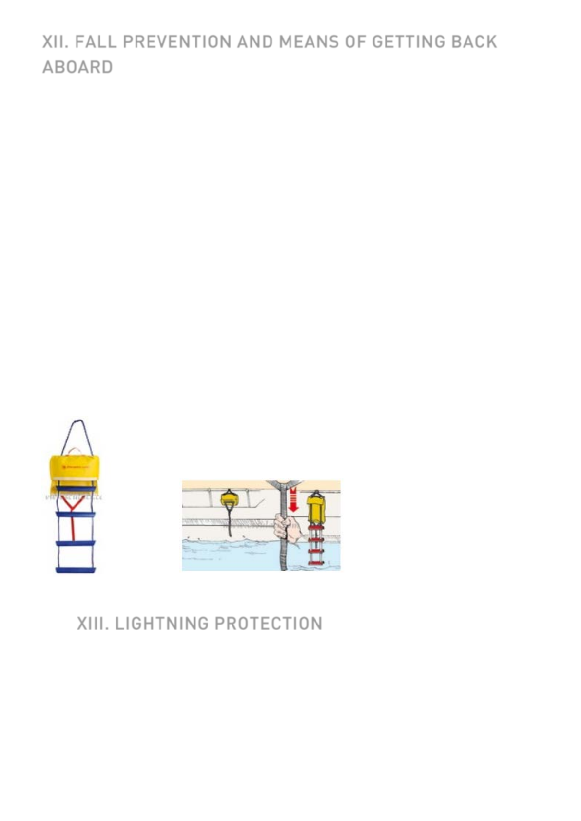
A safety ladder is also provided in case of emergency. It is located on the starboard stern rail, and
can be deployed from the water. Ensure that you are familiar with the system and can operate it
under any circumstances, notably when the vessel is under way.
XIII. LIGHTNING PROTECTION
Your boat is protected against lightning. The rigging is electrically earthed (grounded).
Nonetheless, for your safety, it is necessary to respect certain precautions.
Maintenance
If the vessel has been hit by lightning:
- The protection installation must be inspected to detect physical damage and check
the integrity of the device, as well as the continuity of the earthing.
ENGLISH 29/01/2018 25/86 DUFOUR 360 Grand Large

- The compasses, electrical and electronic devices must be examined in order to
ascertain if damag e or cal ibration changes have occurred.
Protection of people during a thunderstorm
WARNING
During a thunderstorm, it is recommended that you comply with the following instructions:
● People should stay below as much as possible.
● People should stay out of the water and not let their arms or legs hang into the water.
● While maintaining satisfactory control of the vessel and its course, persons aboard should not
touch any parts connected to a lightning protection system, and especially not in such a way as
to form a link between these parts.
● People should avoid touching any metallic parts of the rigging, spars, deck fittings and lifelines.
XIV. ENVIRONMENTAL PROTECTION & SAFETY
We recommend that you find out about local regulations concerning the environment and obey
international regulations against pollution in the marine environment (MARPOL), together with the
codes of good practice.
Do not discharge the toilets or the contents of the holding tanks near coasts or in prohibited areas;
use port or marina pumping systems for emptying the holding tanks before leaving port.
ATTENTION!
● Most cleaning products, engine oils and fuels are likely to impact the environment, so they
should be discharged in authorized locations (check with the Harbor Master’s office).
● Do not run the bilge pump when oil or fuel is present in the engine compartment, as these
chemicals must be discharged in authorized locations.
● Certain products can also pose a risk to your safety and that of others, which is wh y it is
important to read and foll ow the instructions for use.
● Chemicals must be labelled and stored in an appropriate place on the boat.
ENGLISH 29/01/2018 26/86 DUFOUR 360 Grand Large
 Loading...