

Page 1
This electronic device is compliant to the essential requirements of the
European Union (EU) norms, concerning the electromagnetic compatibility and
the electric safety.
DIRRVE - DIRFE
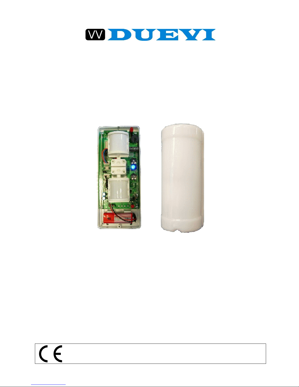
OUTDOOR DUAL-IR SENSOR
USER MANUAL
(VERSION 2.4)
We thank you very much for choosing our product.
Now we would like to invite you to read carefully the following
instructions before installing the product in order to use all its capacities.
Page 2

This manual can be modified without any warning
2
DIRRVE-DIRFE V2.4
DIRRVE – DIRFE
Outdoor DUAL-IR sensor
DIRRVE / DIRFE is an innovative passive infrared sensor for outdoor use. It
has two PIR detection heads that are completely independent and can be
separately adjusted.
This allow to obtain a great functioning versatility and contemporary, if correctly
installed, an excellent reduction of unwanted alarm.
Infact the sensor can work with two different logic combinations between the
two heads: OR logic or AND logic. In OR mode, the sensor gives alarm when
any one of the sensible elements detects a movement. In AND mode, the
sensor gives alarm only when both elements detect a movement. It is also
possible to select a directional AND mode.
ALL THIS MEANS MORE SECURITY
AND LESS UNWANTED ALARMS.
AVAILABLE MODELS:
DIRRVE wireless version
DIRFE wired version
Both the models are identical in functionality and optical performances. They
only differ for the alarm transmission method.
Page 3

This manual can be modified without any warning
3
DIRRVE-DIRFE V2.4
WARNING
DIRRVE-DIRFE HAS BEEN DESIGNED TO GUARANTEE A VERY
HIGH IMMUNITY TO LIGHT INTERFERENCE, HOWEVER VERY
BRIGHT LIGHT CAN PRODUCE A RANGE DECREASE. IT IS
THEREFORE RECOMMENDED TO TAKE GREAT CARE IN
INSTALLATION TO AVOID DIRECT OR REFLECTED SUNLIGHT OR
HIGH INTENSITY LIGHT BEAMS
IT IS RECOMMENDED TO USE THE OUTDOOR SENSOR AS AN
ADDITIONAL TOOL TO A SECURITY SYSTEM AND NOT FOR
ACTIVATING DIRECTLY ALARM TOOLS AS SOUNDERS AND
PHONE DIALLERS
AVOID TO ORIENT THE SENSOR TOWARDS MOVING OBJECTS
SUCH AS BUSHES, FLAGS, BRANCHES ETC, IN ORDER TO AVOID
UNWANTED RELEVATION
IN OUTDOOR INSTALLATION, IT IS RECOMMENDED TO USE THE
SENSOR IN THE “AND MODE” FOR A BEST IMMUNITY TO
UNWANTED ALARMS AND TO SET BOTH ELEMENTS IN THE SAME
DIRECTION. INCORRECT INSTALLATION COULD REDUCE
SECURITY LEVEL.
THE SENSOR DIRRVE HAS AN IP54 PROTECTION LEVEL AGAINST
THE DUST AND WATER. IF POSSIBLE, IT IS ANYWAY
RECOMMENDED TO AVOID INSTALLING THE SENSOR IN AREAS
DIRECTLY EXPOSED TO RAIN OR SNOW. DO NOT SPRAY ANY
HIGH PRESSURE WATER ON THE SENSOR. WHEN POSSIBLE
INSTALL THE SENSOR IN SHELTERED AREAS OR MOUNT IT ON
THE DEDICATED BRACKET (STA).
TO HAVE THE IP54 LEVEL IT IS MANDATORY TO INSERT THE ORING INCLUDED IN THE PACKAGE.
IF YOU DO NOT COMPLY WITH THE ABOVE MENTIONED
RECCOMANDATIONS, IT MAY CAUSE A NOT CORRECT WORKING
OF THE SENSOR AND IN SUCH AN EVENT, THE MANUFACTURER
WILL DECLINE ANY RESPONSIBILITY.
Page 4

This manual can be modified without any warning
4
DIRRVE-DIRFE V2.4
PROPER USE OF THE SENSOR
DIRRVE/DIRFE sensor can be fixed at height between 50 and 250 cm from the
ground level, on vertical surfaces, walls or posts using the fixing and protecting
provided visor.
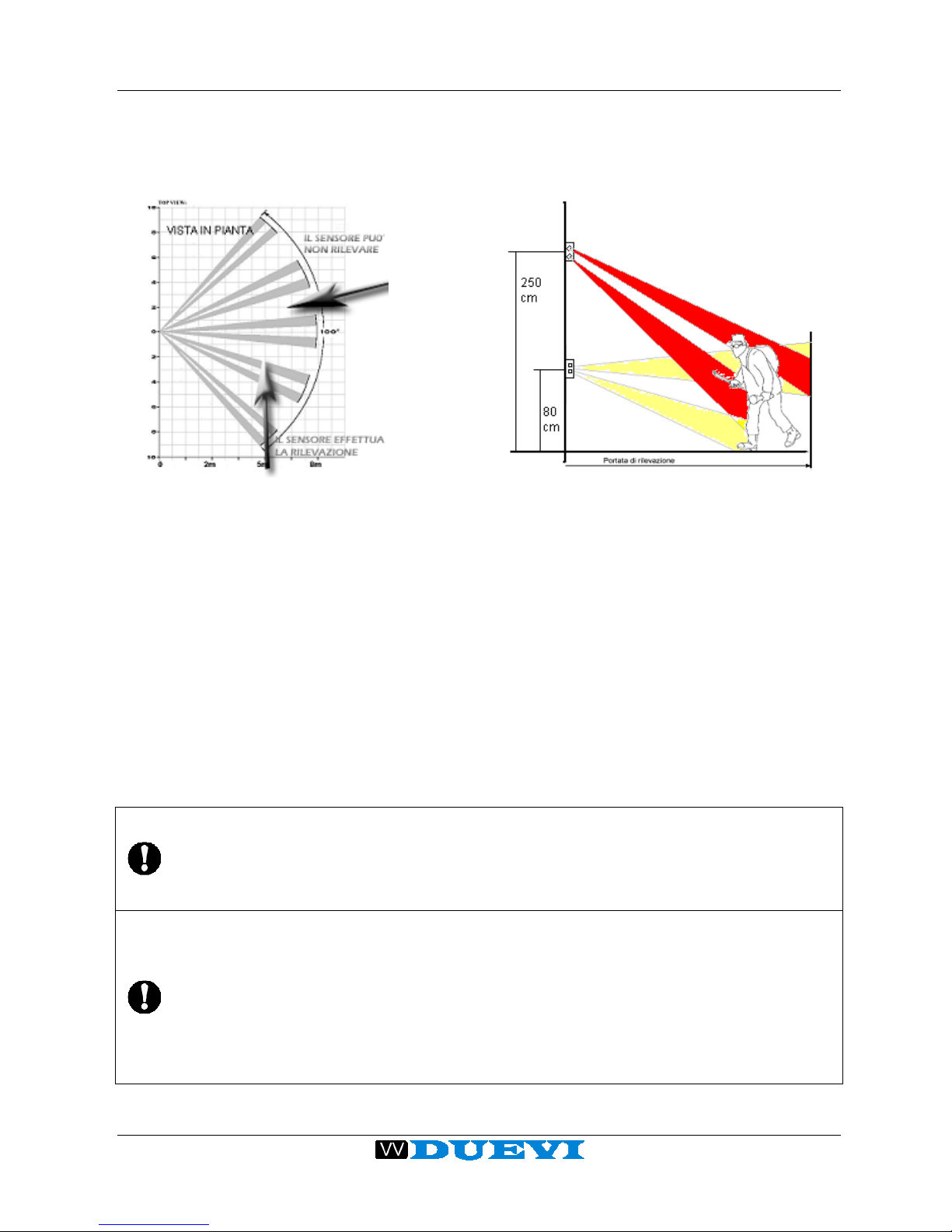
Each detection unit is equipped with a Fresnel lens that builds 5 double sectors
beams horizontally oriented with a radial aperture of 100° (Fig.1).
Fig. 1 - View of the beam’s sectors
NOTICE
The IR sensor is sensible to the “
amount of heat” emitted by a moving
body. The maximum range of the sensor (measured in meters) is referred
to a human body. However the same “
amount of heat” may be emitted by
a smaller body at lower distances, or by a larger one at greater distances.
It should be considered therefore that
the range of any passive infrared
sensor is a RELATIVE measure (referring to a human body) and NOT
ABSOLUTE (for any body).
Range
(m)
IR sensor
Page 5
This manual can be modified without any warning
5
DIRRVE-DIRFE V2.4
OUTDOOR USE
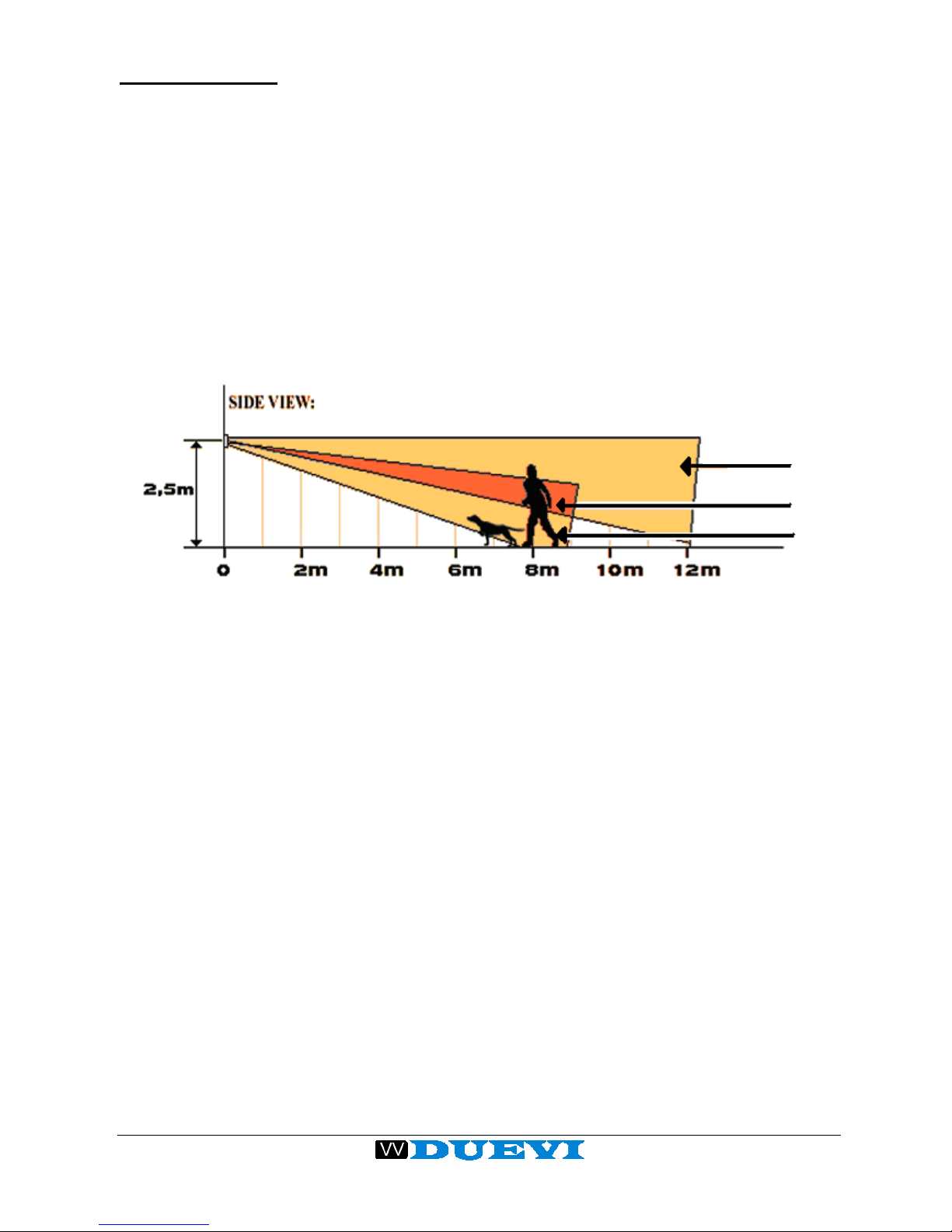
The detecting units MUST be adjusted in order to have beams facing
downward to the ground level or parallel to the ground, but NEVER upward.
This is to avoid situations of blinding by sunlight during the day and to prevent
the not-correct working of the sensor.
The two detecting units MUST be adjusted on the vertical axis in order to the
two beams pattern slight divergent: the upper unit see the most distant area,
the lower one see the nearer area. In this way, using the AND logic, an alrm is
triggered only when a human intruder crosses both the beams. The alarm is
not triggered when only one beam is crossed for example by an animal or
objects that you do not want to be considered intruders.
Fig. 2 - AND logic mode: the human trigger alarm, the dog doesn’t.
The function of "directional AND" allows to further refine the way in which an
alarm is triggered. This mode make the sensor to trigger an alarm only after a
sequence of detection that starts with the upper head (farther beams) and end,
within the AND period, with the lower head (closest beams).
This feature allows to give a directionality to the detection, that means the
sensor is able to identify an intruder approaching the protected zone, avoiding
alarms for people who, even if moving inside the detection zone of the upper
head, are not approaching the protected zone.
NO ALARM
ALARM
NO
ALARM
Page 6

This manual can be modified without any warning
6
DIRRVE-DIRFE V2.4
NOTICE
Take in consideration that small alterations of the head position
corresponds to large modifications (at distance of 8 m) of the beams
detecting zones.
Consider that a 1° horizontal rotation of the head corresponds to a 14 cm
shift of the beams at a distance of 8 m.
It is then recommended to execute a very meticulous regulation
and several tests in order to obtain the wanted result.
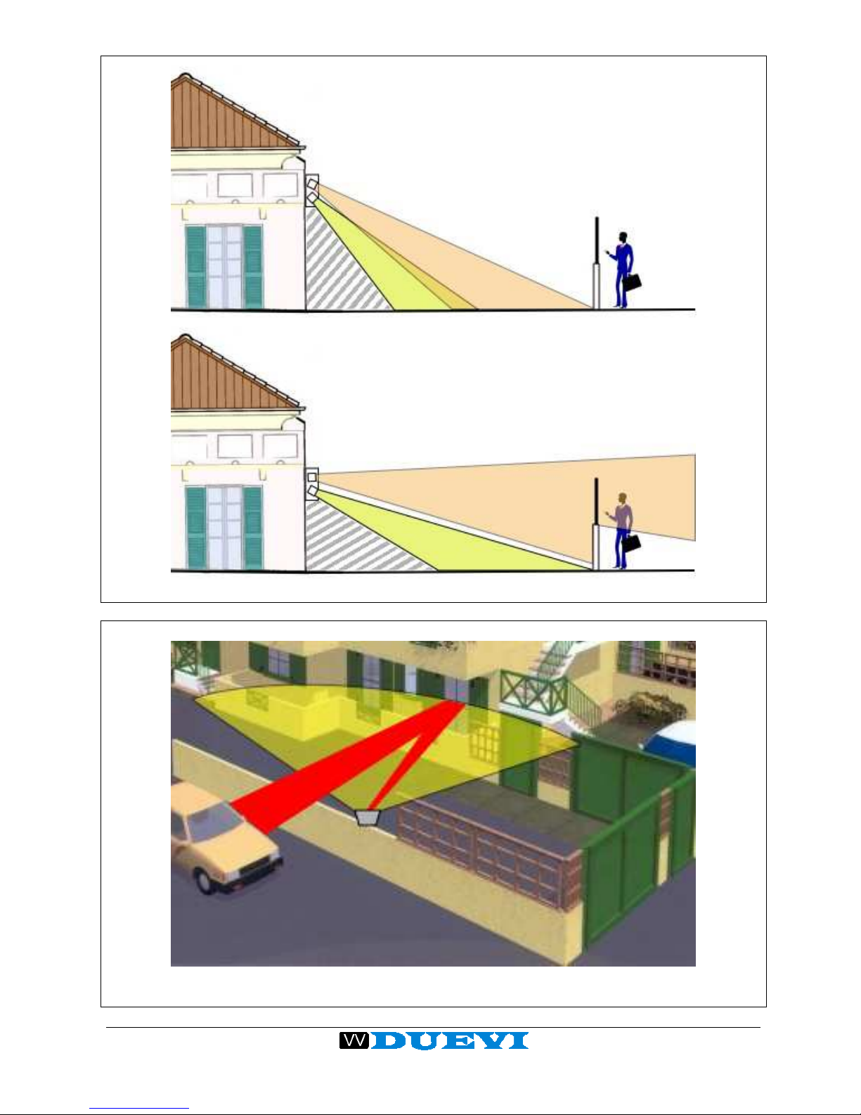
To avoid unwanted alarms, NEVER adjust detecting heads allowing the
beams to be parallel to the ground level.
The beams should always finish against some surface (wall, ground) to
have a well-defined detection area not pointing towards the open space
(see Fig. 3).
NEVER ADJUST heads directly toward reflective surfaces, in order to
prevent unwanted alarms. Typical examples of reflective surfaces are:
windows, glass walls, water puddles, wet roads, smooth concrete
surfaces, paved roads. The amount of reflection of these surfaces is not
of course 100 %, however, if the heat source is very strong, reflection
may be sufficient to trigger an alarm (see Fig. 4).
Page 7
This manual can be modified without any warning
7
DIRRVE-DIRFE V2.4
Fig. 3 - Avoid to have beams parallel to the ground level.
Fig. 4 - Avoid to have beams toward reflecting surfaces.
NO!!
NO!!
OK
Page 8
This manual can be modified without any warning
8
DIRRVE-DIRFE V2.4
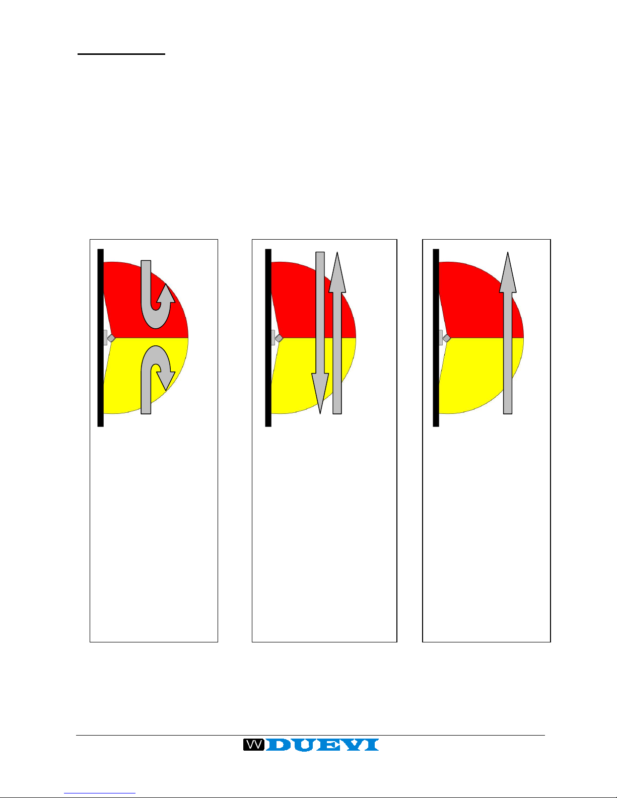
(1) OR Logic
The sensor gives
alarm when it detects
a movement in any of
the areas covered by
the two heads.
DIP1=ON
(2) AND Logic
The sensor gives alarm
only when it detects a
movement crossing both
the areas, not
considering the direction.
The movement inside
only one area do not
trigger an alarm.
DIP1=OFF
DIP3=OFF
(3) Directional AND
Logic
The sensor gives
alarm only when it
detects movement
crossing from the
upper head area to
the lower one.
DIP1=OFF
DIP3=ON
INDOOR USE
The indoor installation allows greater flexibility of use, as sources of unwanted
alarms are significantly reduced compared to the outdoor environment.
In addition to the modes already described for the outdoor use, it is possible to
adjust the detection heads also divergent in the horizontal plane. This allows to
get different combinations of protection.
For example it is possible to adjust heads forming a 90° angle in order to obtain
a protected zone with semicircle shape, equivalent to that generated by 180°
aperture lens. According to the selected logic (OR, AND, directional AND) you
can have the sensor working in different ways.
Top view Top view Top view
Upper
head
Lower
head
Page 9
This manual can be modified without any warning
9
DIRRVE-DIRFE V2.4
INSTALLATION OF THE SENSOR
Mount the sensor at height between 80 cm and 250 cm from the ground level.
Position the sensor considering the coverage of an area with maximum
distance of 8 m and radial aperture of 100 degrees.
For a reliable and repeatable detection, it is recommended to install the sensor
so that the intruder cross beams perpendicularly and not with a frontal
approach.
Once positioned the sensor, to adjust the heads, it is advisable to slightly
untighten the screws of joints.
Proceed with the "calibration" of the sensitivity of detections heads, starting
with the minimum value of sensitivity (trimmer completely rotated counterclockwise) and the heads as downward as possible. Increase gradually
sensitivity and orientation of the heads in order to obtain a detection only in the
area that is to be protected and no alarms outside that area.
Once finished the adjustment, tighten the screws of joints.
NOTICE
The external cover of the sensor causes an attenuation of about 30
% of
the length of the beams. T
his should be considered during the setting
operations.
WARNING
POWERING THE SENSOR WHILE THE TAMPER JUMPERS ARE
CLOSED WILL DISABLE THE SUPERVISION CODE TRANSMISSION.
THIS IS SIGNALED BY THE BLINKING OF THE BLUE LED (10
TIMES).
THE SENSOR WILL BE ACTIVE AND STABLE ONLY ABOUT 20 S
AFTER THE RED LEDS START BLINKING.
Page 10
This manual can be modified without any warning
10
DIRRVE-DIRFE V2.4
PARTIAL COVERING OF THE LENS
In some environment the detection area of the heads can be too wide and be a
potential source of problems if inside the area to be protected there are tree
branches, curtains, windows, etc.
Under these conditions it is possible to reduce the detection area by masking
appropriately lateral or intermediate beams with adhesive tape placed over
sectors of head lens (beams blinding), leaving it able to detect only the beams
oriented towards stable zones of detection.
This precaution avoids unwanted alarms raised by wind, moving branches,
curtains or other objects present in the area.
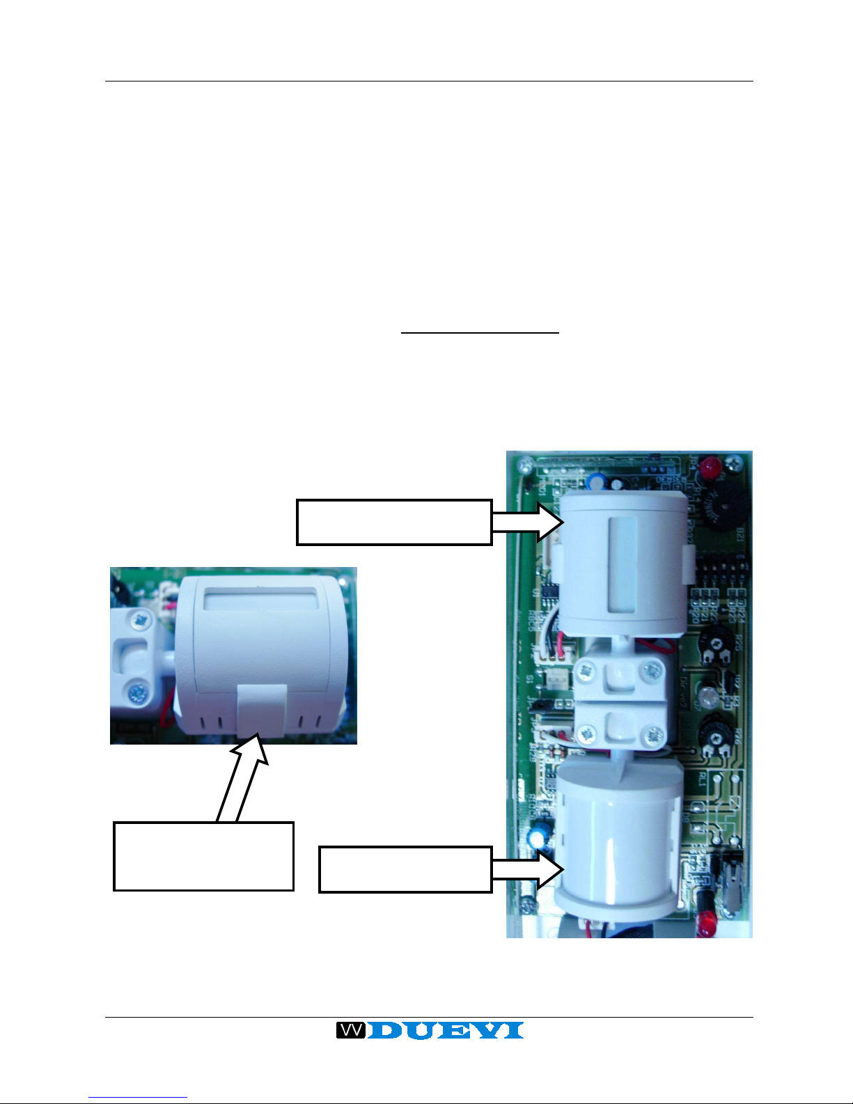
In the sensor package are included two plastic lens-covers to be applied to the
detection heads in order to obtain a CURTAIN EFFECT. With such a cover, the
beam detection sector is reduced to 20°, having the same detection range.
The lens cover is to be inserted pressing it on the detection head as showed in
following figures. Pay attention to correctly lock the two hook on the sides of
the cover and that the lens cover is well fixed on the detection head.
HEAD WITH
STANDARD LENS
HEAD WITH CURTAIN
EFFECT LENS COVER
VERI
FY THAT THE
HOOKS ARE WELL
FIXED IN THEIR JOINT
Page 11
This manual can be modified without any warning
11
DIRRVE-DIRFE V2.4
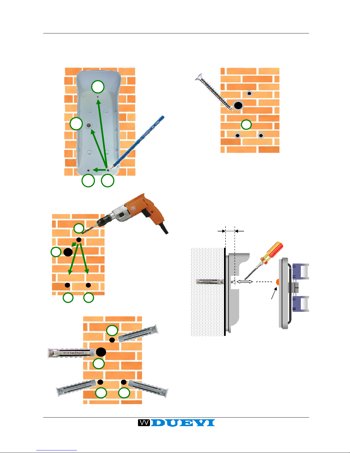
WALL MOUNTING
1. Use the visor as mask to mark the position
of holes on wall (A and B), then drill and
insert provided dowels:
2. Insert the TAMPER adjustment screw in
dowel (B) leaving protrude its head about
9 ÷ 10 mm from wall surface:
3. Overlap the visor to the detector: fine
adjust TAMPER screw so that fixing the
detector, the tamper switch is well pressed
without break circuit:
TAMPER
protection
headset
Visor Detector
About
9 ÷ 10 mm
A
A
A
B
A
A A
B
TAMPER
adjustment
Wall
TAMPER
adjustment
screw
Page 12
This manual can be modified without any warning
12
DIRRVE-DIRFE V2.4
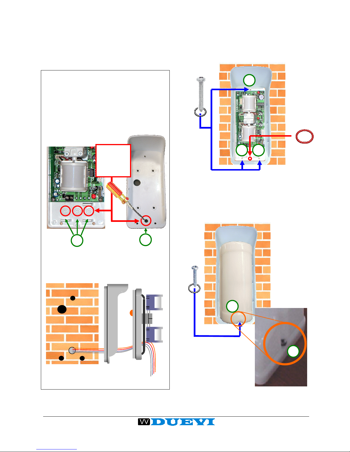
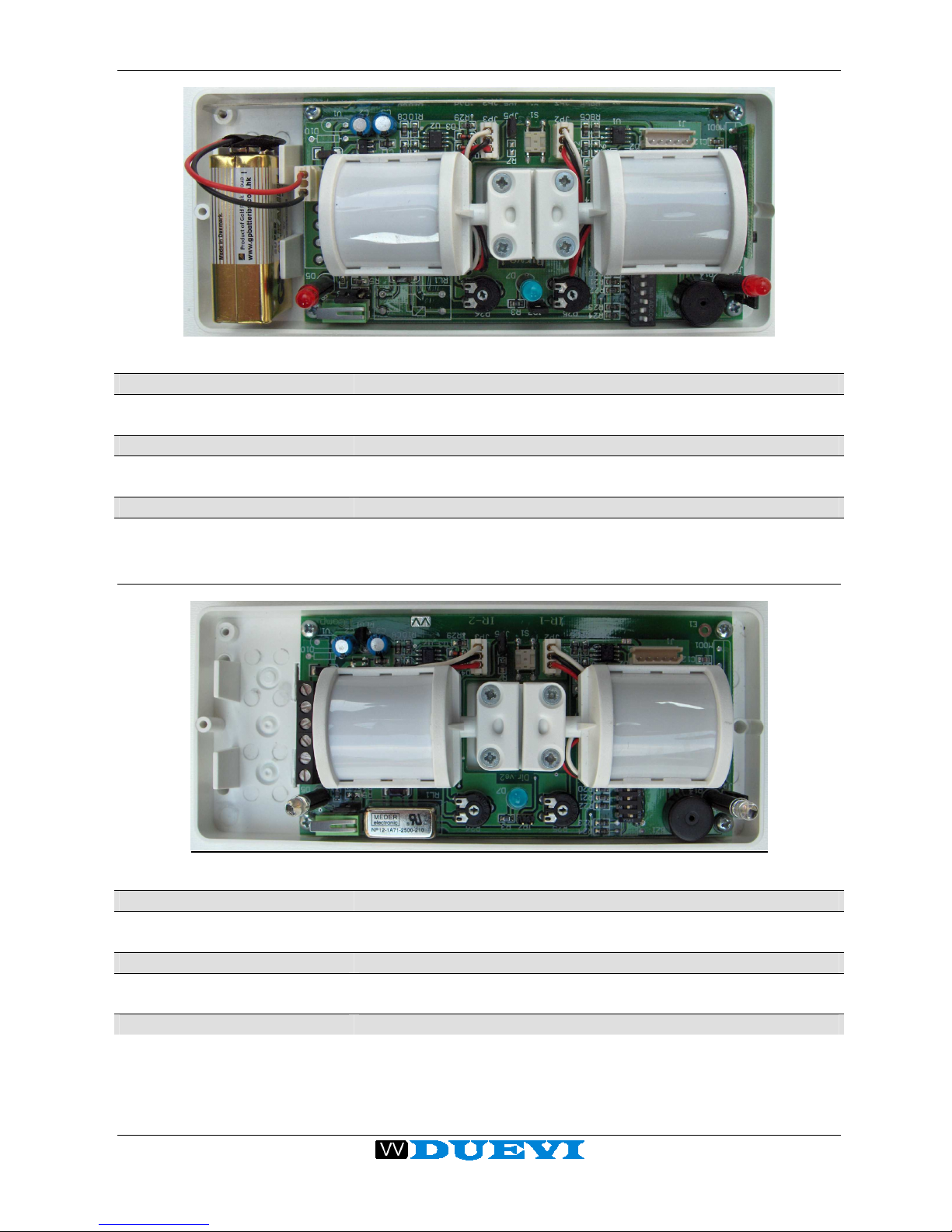
Note for DIRFE version
Before fix the detector to wall it is necessary
to pass the cables through appropriate holes.
Break one or more pre-marked hole-places
(up to needs) on visor (C) and detector
support platform (D):
Pass cables through holes (C and D) and
proceed with installation as follows.
4. Fix detector and visor to wall (E points
matching to A holes) by the three
appropriate screws, taking care to add
BLACK o-rings on each and placing the
RED o-ring in its appropriate position:
5. Insert the cover over detector platform
starting from the top (hooking the two
locking tabs). Fix (F) the cover by
appropriate screw taking care to insert the
BLACK o-ring:
Cables path
Break
septums
for passing
cables
DIRFE
detector
Visor
D C
E
E
E
x 3
Place here
RED O-ring
x 1
F
F
Page 13
This manual can be modified without any warning
13
DIRRVE-DIRFE V2.4
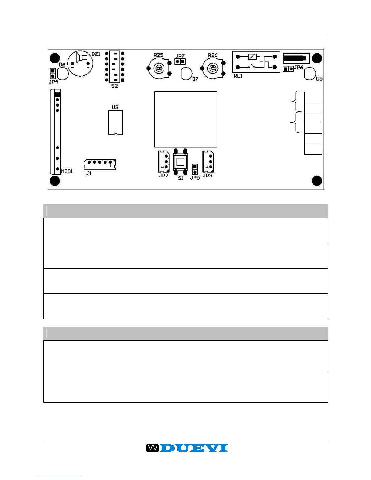
LAYOUT AND SETTINGS
JUMPERS
JP5 Wall Tamper Closed = tamper disabled
Open = tamper enabled
JP6 Cover Tamper Closed = tamper disabled
Open = tamper enabled
JP4 Testing Buzzer Closed = buzzer enabled
(only when DIP4 ON) Open = buzzer disabled
JP7 Alarm Led (BLUE) Closed = led enabled
Open = led disabled
RANGE TRIMMER
R25 Upper head Trimmer to adjust the detection depth of the upper
head. Turn clockwise to increase the detection
range.
R26 Lower head Trimmer to adjust the detection depth of the lower
head. Turn clockwise to increase the detection
range.
TAMPER
ALARM
GND
+12 V
Page 14

This manual can be modified without any warning
14
DIRRVE-DIRFE V2.4
DIP-SWITCH
DIP1 Sensor Logic OFF = heads work with AND logic
ON = heads work with OR logic
DIP2 IR sensitivity OFF = HIGH sensitivity (for indoor use)
ON = LOW sensitivity (for outdoor use)
DIP3 AND-mode
selection
OFF = NORMAL AND
Alarm is triggered with a detection that starts from any
head and, within the AND time, ends by the detection
of the other head. If during the “AND” time the second
head doesn’t detect anything, the sensor returns in
stand-by mode.
ON = DIRECTIONAL AND
Alarm is triggered only with a detection that starts
from the upper head and, within the AND time, ends
by the detection of the lower head. If during the “AND”
time the lower head doesn’t detect anything, the
sensor returns in stand-by mode.
DIP4 Test OFF = Normal Operation (Test OFF)
ON = Test Mode
It enables the detection led of any head, the alarm led
and the buzzer emission (if JP4 is closed), useful to
test the coverage area.
OFF = Normal Operation DIP5 Continuous
Transmission
(DIRRVE
MODEL)
ON = Enables the wireless transmission once a
second to test the maximum transmission range.
DIP6
(*)
Continuous
Detection
(DIRRVE
MODEL)
OFF = Detection with quiet time
Alarm is triggered only if occurs a time gap of more
than 30 seconds (quiet time) from the last alarm. If
within this time it is detected another movement, the
sensor resets to zero the quiet time. If no movement
is detected, after the quiet time the sensor is ready to
trigger a new alarm. This function is particularly useful
in very crowded places, to extend the battery life.
ON = Continuous detection
Alarm is triggered every time heads detect a
movement.
(*) NOTICE: When DIP6 is changed from OFF to ON, before to obtain a
real change in working mode, it is mandatory to avoid the sensor to
detect a movemen until the quiet time is ended, otherwise the sensor will
continue to work as the DIP6 is in the OFF position.
Page 15
This manual can be modified without any warning
15
DIRRVE-DIRFE V2.4
TECHNICAL FEATURES (DIRRVE – wireless)
POWER SUPPLY Battery 9 V
CONSUMPTION Stand-by < 15 uA – ALARM < 10 mA
LOCAL SIGNALLING
1 Led for upper head, 1 Led for lower head, 1 Led for alarm
transmission
ALARM INPUTS 2 IR sensible elements, programmable with OR / AND logic
TEST
Test function selectable by dipswitch with led display and
buzzer
WIRELESS SECTION TX 433,92 MHz (100 m range)
REMOTE SIGNALLING TX alarm, tamper, low battery, supervision.
TECHNICAL FEATURES (DIRFE – wired)
POWER SUPPLY 12 VDC
CONSUMPTION Stand-by < 20 mA – ALARM < 100 mA
LOCAL SIGNALLING
1 Led for upper head, 1 Led for lower head, 1 Led for alarm
transmission
ALARM INPUTS 2 IR sensible elements, programmable with OR / AND logic
TEST
Test function selectable by dipswitch with led display and
buzzer
OUTPUTS Alarm relay, Tamper.
 Loading...