

1
Made in Italy
CE818
User Manual
14.07-M1.5.1-H2.0-F1.41-S1.41-ENG

2
FEATURES OF YOUR SECURITY SYSTEM
The core of your security system is the CE818 control panel, an intelligent microprocessor device that
oversees the safety of persons and your home.
The control panel manage up to 16 zones protect by sensors and contacts, and receives commands
from LCD keyboards (Advanced mode) and electronic key readers.
The system can be activated in different modes (depending on the working mode); for example, during
night, you can activate the protection only on living room or on the perimeter of your house, having
the possibility to freely move inside at system activated.
It is possible to add a GSM or PSTN communicator (optional) to provide you an intelligent remote alarm
signalling.
In case of alarm, the phone communicator will inform you with a vocal message or SMS, allowing you –
even when you are away – to monitor in real time what happens in your home.
From landline or mobile phone you can verify the status of your panel and the whole system or send a
command to the system.
WORKING MODE
The control panel can work in two modes:
Base Mode
Advanced Mode
Depending on the selected mode, the control panel can be equipped with accessories and functions.
Verify in which mode your control panel is working.
It is possible to select the working mode to favour both installer and user: the base system is expandable
at any time just restarting the control panel in advanced mode adding peripherals, zones, functions…
3
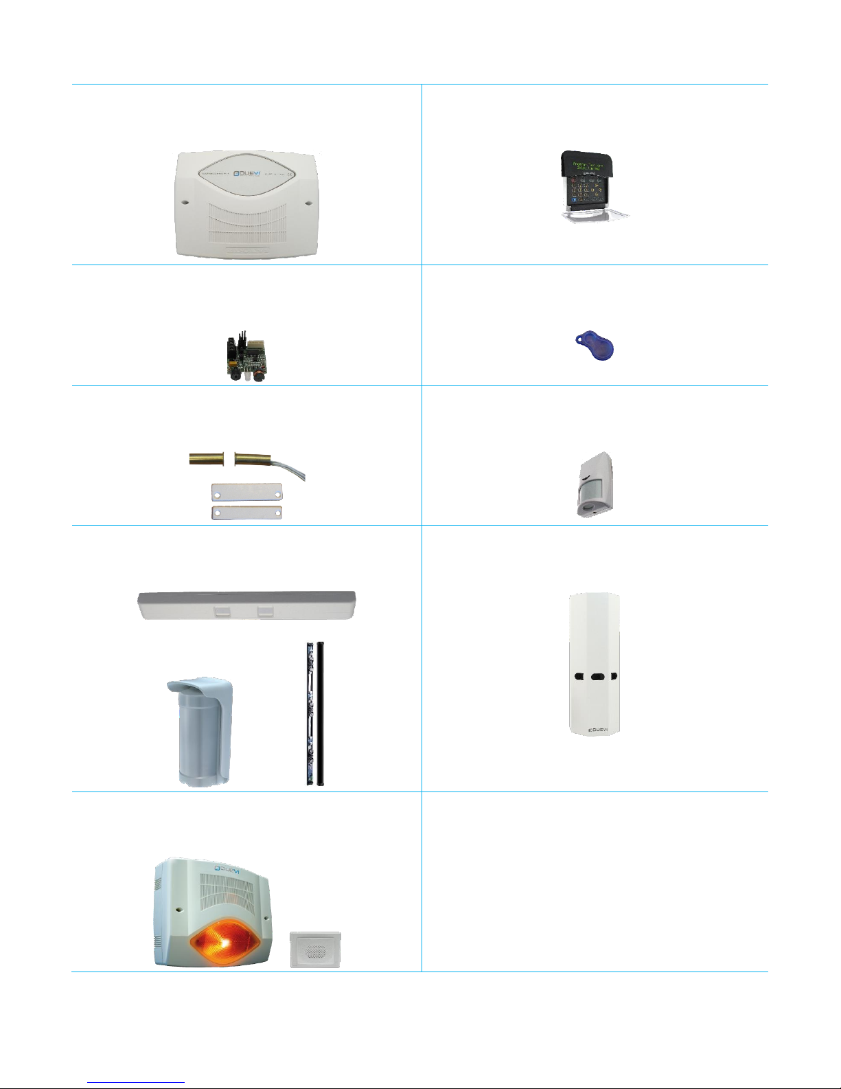
SYSTEM DEVICES
CE818
Electronic Control Panel
DVT-LCD / DVT-OLED
LCD/OLED wired keyboard
LET-485
Wired electronic keys reader
CHT
Transponder electronic key
ASIG / ASC / ABASC
Wired magnetic contacts
DIRF, DIRRPV, DDT-S
Single and double technology indoor sensors
E-Wall, DIRFE, barriers, MOSKITO-F
Outdoor wired sensors and barriers
PEPEROSSO
Wired dissuader
DVSIR, DVSIR-PROX, DVPZ
Wired sirens

4
GLOSSARY
Alert
Function for generate a “din-don” tone from keyboards and key readers AT
SYSTEM DISARMED when selected zones are violated
Power Fail
If the 230 VAC power line fall down for a long time (programmable timing), the
control panel will advice and activate a dedicated output (automatic restore
when power line backs up).
Useful for example to activate a phone call in case of black out
Beep
Word to indicate a treble sound emitted by keyboard or key reader each time
a button is pressed, you interact with the system or to signal an event
Boop
As per “Beep”, this word indicates a bass sound emitted by keyboard or key
reader in particular circumstances
Buzzer
Sound generator inside keyboards and key readers
Electornic Key
Electronic key with digital security code enabled to activate/deactivate the
control panel. Must be used with the key reader
Remote Code
(only if connected the GSM dialler and/or the PSTN module) Four digit security
code for use of GSM/PSTN commands and functions. This code must be
inserted in each command sent to the dialler.
User Code
Six digit code used to access to alarm system using the keyboard
Coercion
This function allow to obtain a silent alarm signalling in case you are forced to
disarm the system under menace.
It is possible to use this function in two modes:
• after the disarming of the system do NOT press any directional key on
DVT-LCD/OLED keyboard within programmed time
• press a dedicated button connected by wire to one of the input of the
control panel
PSTN Dialler
Device – optional – to send vocal messages via landline connection. In this
control panel this device is an additional module installed onboard
GSM Dialler
Additional external device (optional) to send vocal and SMS messages using
the GSM network service. The connection with the control panel is realized on
BUS 485 (mod. GSM BUS)
Exclusion/bypass
Function that allow the user to exclude the wanted zones so to bypass them at
system armed
Arming / Disarming
Action of the user to activate/deactivate the alarm system. At system armed
the violation of a zone generates alarm. At system disarmed the violation of
the zones does not generate alarm.
LED
Lights, for different signallings, on keyboards and key readers
Key Reader
These devices read the transponder electronic keys

5
User Menu
(only in ADVANCED mode) Special menu with control panel options, only for
Master users. In this menu it is possible, for example, to set date and time,
manage other users, bypass zones, etc.
Monitor (zone)
A zone sets as MONITOR, when violated, cause only the buzzer sound on
keyboards and key readers (not sirens) for 30 seconds.
Function useful for example in case you want to protect an external area, and
just be warned when you are at home.
Panic (wired)
Press a dedicated button to start the siren sound for a fixed time of 30
seconds, in order to draw attention. The panic vocal call and SMS are send (if
enabled).
Partialization
Special arming mode of control panel, it exclude a group of zones. In this way
a part of the protected area will not be monitored by the system and it will be
possible to move inside this area without alarm even if the system is armed
BUS device
Device connected to control panel by a 4 wires cable (BUS RS485) (usually
keyboards, key readers and expansion boards)
PreAlarm
Only for PARTIAL armings.
At the start of alarm, the siren sounds at low level – for a programmed time –
and then continue at high level.
During the pre-alarm no SMS or vocal call are sent.
Sensor
Device for violation detection with different technologies (glass breaking,
intrusion, door opening, ecc.)
Sounds
On keyboards some sounds are disabled – with variable time – when the user
or installer make some operation:
simple operations sounds disabled for about 30 seconds
programming or event queue sounds disabled for 10 minutes
The disabled sounds are:
entry and exit sounds
pre-alarm
monitor and technologic
maintenance
LCD / OLED
keyboard
Keyboard provided with display LCD / OLED, buttons and LEDs and with which
the user/installer interact with the alarm system. The keyboard allows the
control panel programming.
Entry Time
It is possible to program some zone – when violated – to cause siren sound
only after a certain time.
Useful for example if the control panel is far from entry door and it is
necessary to go near to it to disarm the system.
Exit Time
It is possible to set a time that allow to arm the system and exit from the
building without generate alarm.
Output
There are four outputs on control panel, which are activated according to
some combined event (ex.: to switch on a lamp in case of alarm or to activate
a phone dialler)
BASE mode: the outputs are pre-programmed

6
ADVANCED mode: it is possible to customize the events that activate each
outputs (for a complete list ask to your installer).
Guest User
Guest users can arm and disarm the system only if enabled by a Master user.
Master User
Master users have high privileges on the system (except for installation and
system configuration changes).
Master users actions:
arm (any mode) and disarm the system
access to User menu
add, delete and change other user settings
make system tests
Patrol User
Patrol users cannot arm or disarm the system but – at system armed – bypass
for a certain time the zones set for this behavior.
This function is useful for example to allow the access only in certain areas,
without disarm the system (service staff).
Zone
A zone manage all the sensors connected to it.
The zone corresponds, usually, to a protected area of the building, a local or
simply to a single sensor
Technologic Zone
A zone set as TECHNOLOGIC is active 24 hours / 24, so it is NOT subject to
arming or disarming of the system.
In case of detection, the zone cause an alarm with low level siren sounding.
Function useful for example in case of flood-sensors, smoke-sensors, gassensors, and so on…
Example: it is possible to have immediate signalling of a gas leakage and drive
an electric valve (using one of the outputs) to block the gas flux and avoid the
danger.
7
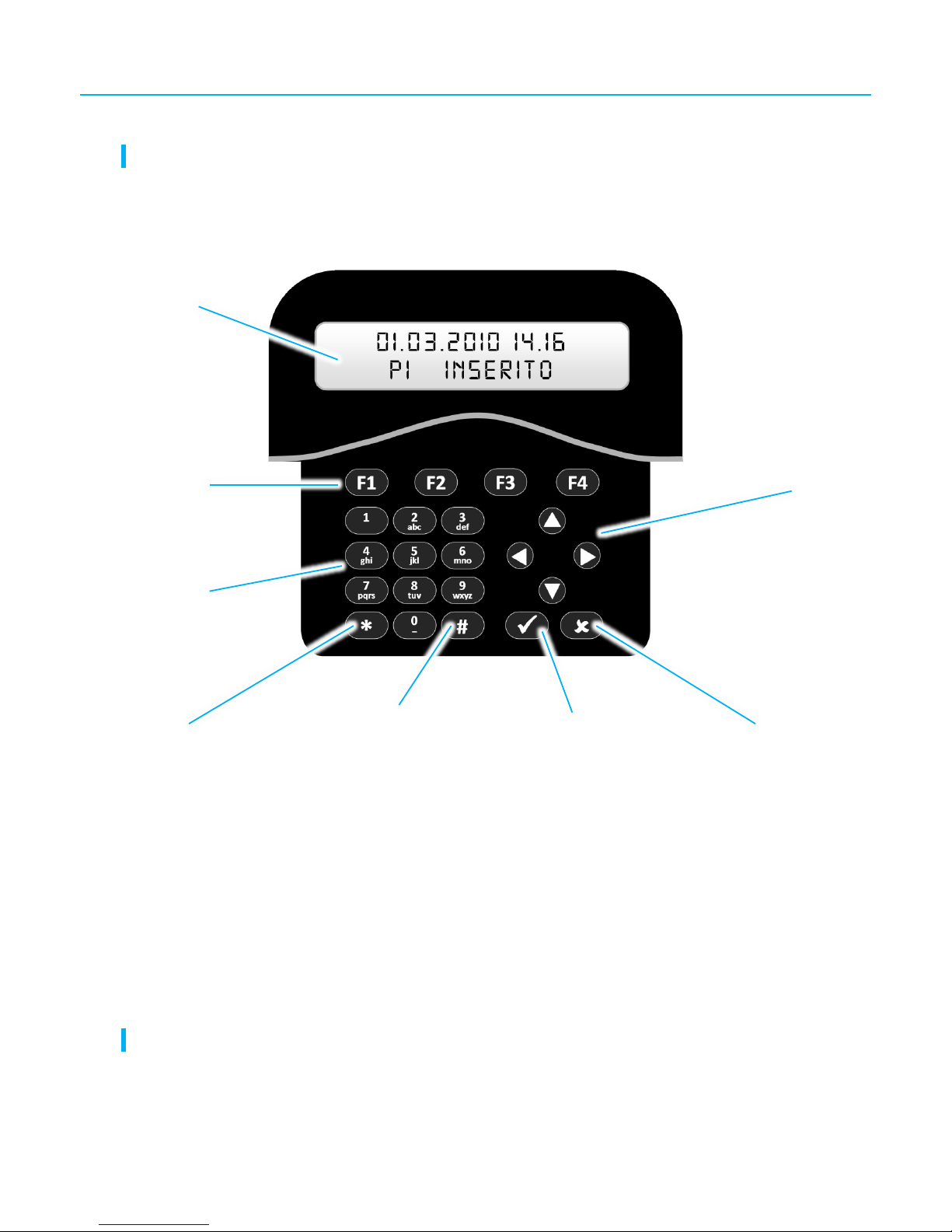
KEYBOARD
THE KEYBOARD CAN BE USED ONLY WITH CONTROL PANEL IN ADVANCED MODE
Follows the description of buttons and functions of the keyboard:
The keyboard allow to control your alarm system:
visualize the system status, functions and other alerts
arm and disarm
user management
visualize system events and alarms
ALWAYS CHECK ON DISPLAY YOUR CORRECT OPERATING
Backlit display
Arming buttons /
Sysem status
Directional
buttons
Alphanumeric
buttons
OK button
CANCEL button
Button “*”/
ALERT status
Button “#”/
DISARM

8
KEYBOARD USERS (ONLY ADVANCED MODE)
The control panel manage up to 16 users
Each user can be set as:
o MASTER
Master user can arm and disarm the control panel without limitations.
It has access to User menu to change other users, bypass zones, change date and time and
perform a system test.
o PATROL
At system armed, the Patrol user can bypass some zone (all the ones set as Patrol) to access
in wanted areas without cause alarm.
The control panel stays armed, so if the user violates a zone not set as Patrol (R), the control
panel will detect alarm.
When leaving, the Patrol user can include again the bypassed zones, or it is possible to set an
auto-rehabilitation time.
Patrol user has no access to User menu.
o GUEST
Guest user has limited access and can only arm according to Master user and Installer permits.
The Guest user can disarm the control panel only if enabled.
Guest user has no access to User menu.
Each user has a six digits code (changeable) to arm and disarm the system
Each user can have a combined electronic key (see next paragraph)
It is possible to enable an SMS/vocal message each time each user act on the system
9
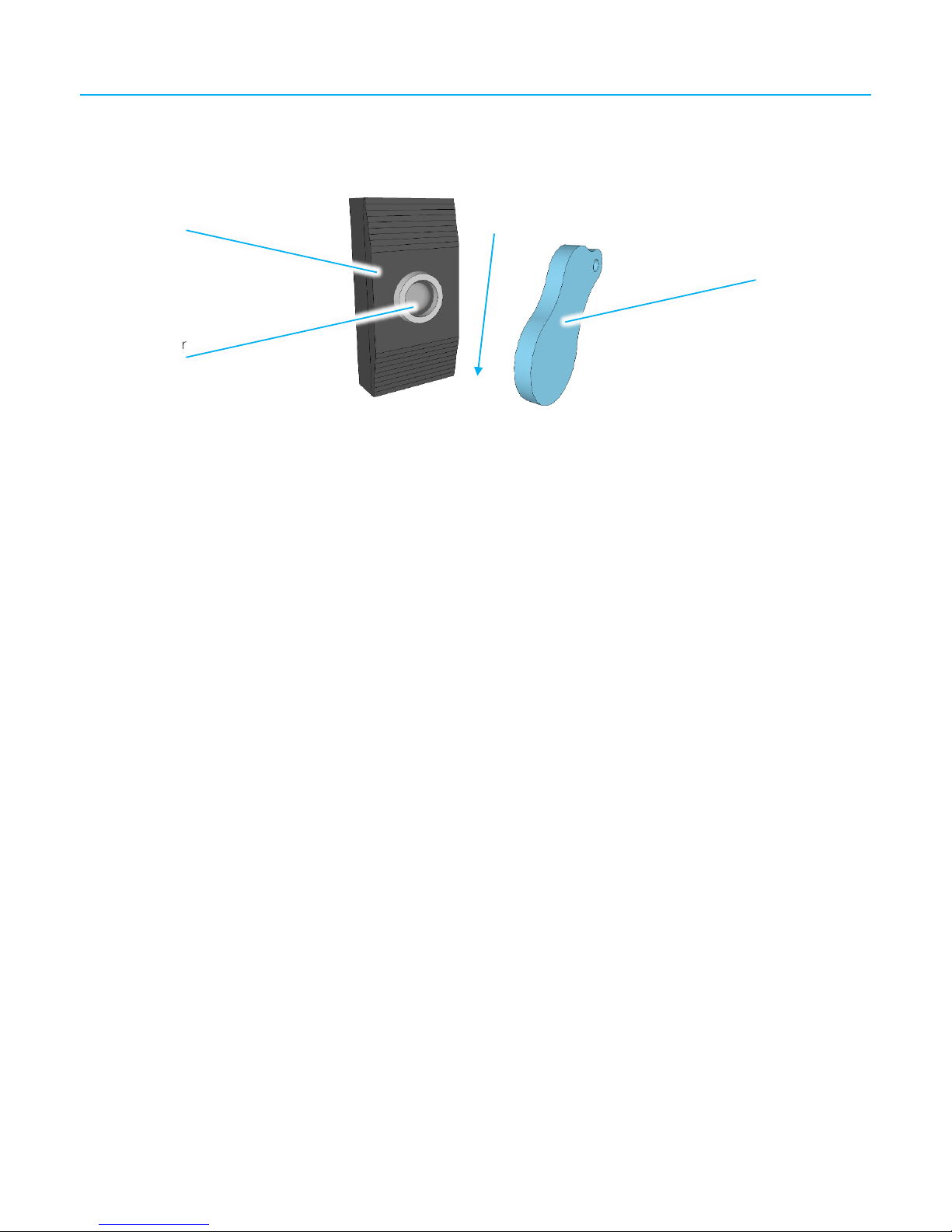
ELECTRONIC KEYS AND KEY READER
The electronic keys are read by key readers.
With the keys it is only possible to arm and disarm the system.
BASE mode
Each key stored is an user.
The control panel can store up to 12 electronic keys.
All the keys have the same privileges, can arm in Total, Partial and Disarm the system
ADVANCED mode
At each user can be combined one electronic key (up to 16 users)
If the user is set as MASTER, its key will arm and disarm without restrictions.
If the user is set as GUEST, the key arm and disarm the system according to the privileges allowed by
the Master user.
If the user is set as PATROL, the key bypasses/rehabilitates the Patrol zones.
Electronic
key
Multicolour
LED
Key reader

10
BASE MODE

11
BASE mode
8 wired zones
Max 12 electronic keys to arm the system
Small system (max 8 wired zones) but with all essential functions
Max 4 key readers
Two arming modes: Total and Partial
Alarm system upgradeable without change the control panel
Communication via GSM (optional)
Zones
8 on-board zones (not expandeable)
Zone 1: with entry time
Zones 2 ÷8: instantaneous
Exit time
30” (+ 30” in case of opened doors)
Fixed
Entry time
30”
Fixed
Alarm time
120”
Fixed
Alarm cycles
From same zone: 4
Fixed
In same arming cycle: 10
Fixed
Vocal calls
1 for each telephone number
Only “alarm” call (if GSM-BUS installed)
Arming modes
Total
Included zones: from 1 to 8
Partial
Included zones: from 1 to 5 (not 6, 7, 8)
Electronic keys (CHT)
Max 12 *
BUS 485 devices
LET-485
Max 4
GSM-BUS
Max 1
Outputs
Output 1
Total armed
Output 2
Partial armed
Output 3
TC Output 4
Low battery buzzer (active until battery restore)
Battery
12 V / 7,5 Ah
* Only the installer can add/delete electronic keys

12
ARMING / DISARMING
TOTAL ARMING
To arm the system in TOTAL mode, pass once a CHT key over a key reader.
A confirming “beep” is emitted and the RED LED lights solid on key reader.
A “beep” series for about 30 seconds (exit time) are emitted, then the system is armed.
TOTAL arming
Active zones
All (zone 1 ÷ zone 8)
The zone 1 is Delayed (Entry time = 30 s)
Sound alerts
One “beep” to confirm arming
A “beep” series during Exit time (30 s)
LED on LET-485
RED, solid on
Control panel
outputs
Output 1 (“Total armed”) changes status
Output 3 (“TC”) changes status
GSM alerts *
SMS for “Total armed” to enabled numbers
* If GSM module installed
PARTIAL ARMING
To arm the system in PARTIAL mode, pass twice a CHT key over a key reader.
A confirming “beep” is emitted and the GREEN LED lights solid on key reader.
To arm it is also possible to hold the key over the key reader until the GREEN LED lights on (corresponding
to Partial arming) then remove it.
A “beep” series for about 30 seconds (exit time) are emitted, then the system is armed.
PARTIAL arming
Active zones
Only zones 1 ÷ 5
Zones 6 ÷ 8 are disabled
The zone 1 is Delayed (Entry time = 30 s)
Sound alerts
One “beep” to confirm arming
A “beep” series during Exit time (30 s)
LED on LET-485
GREEN, solid on
Control panel
outputs
Output 2 (“Partial arming”) changes status
Output 3 (“TC”) changes status
GSM alerts *
SMS for “Partial armed” to enabled numbers
* If GSM module installed

13
OPENED DOORS (ZONES)
If the system is armed with one or more opened zones, a quick “beep” serie is emitted.
After 30 seconds of this “opened zones” signalling in addiction to the 30 seconds of “exit time”, the control
panel will arm normally but the opened zones will be temporary bypassed.
If these bypassed zones are then closed at system armed, they will be activated: at this point they will generate
alarm if violated.
DISARMING (WITHOUT ALARM)
To disarm the system, pass once a CHT key over a key reader.
A confirming “beep” is emitted and the LED switch off on key reader.
DISARMING
Zones
All the zones are disabled
Sound alerts
One “beep” to confirm disarming
In case entering by zone 1 before disarm, a “beep”
series signals the Entry time (30 s)
LED on LET-485
OFF *
Control panel
outputs
Output 1 or 2 (arming type) changes status
Output 3 (“TC”) changes status
GSM alerts **
SMS for “Disarmed” to enabled numbers
* If no alarm event during arming
** If GSM module installed
DISARMING (WITH ALARM)
In case of alarm, disarm as descrived above.
The siren stops sounding and all the alerts via GSM/PSTN are interrupted (SMS or calls – if GSM/PSTN module
installed).
The LED on key readers will blink RED as many times as the last violated zone number. The blinking is
repeated after a pause of 3 seconds, for the whole duration of alarm memory (about 1 minute).
To read the Event log, download it from control panel on a USB memory (option for installer).

14
KEY READERS FEEDBACK
When control panel is on and disarmed the LED on key reader is normally OFF.
The LED lights on to signals events:
LED
OFF
ON
BLINKING
Red
Disarmed / Off
TOTAL armed
Alarm memory, number of last violated zone (at
disarming, for 60 seconds)
Green
Disarmed / Off
PARTIAL armed
-
Multicolour
- - Not possible to communicate with control panel

15
ADVANCED MODE

16
ADVANCED mode
8 onboard wired zones + 8 wired zones on expansion board + 1 zone on each
DVT-LCD/OLED keyboard
Max 16 electronic keys
Max 16 keyboard users
Max 4 LCD/OLED keyboards
Max 4 key readers
System with advanced functions
Medium/large alarm system (max 16 wired zones)
Three arming types (customizable): Total, Partial 1 and Partial 2
Auto-arming and Patrol
GSM communication (optional)
USB/software programming
Zones: on-board
8 zones
Zone 1 (IN1): with entry time *
Zones 2 ÷8 (IN2 ÷ IN8): instantaneous *
Zones: on expansion board
8 zones
Exit time
30” (+ 30” in case of opened doors) *
Changeable
Entry time
30” *
Changeable
Alarm time
120” *
Changeable
Alarm cycles
From same zone: 4
Fixed
In same arming cycle: 10
Fixed
Vocal calls
1 for each telephone number *
Only “alarm” call (if GSM-BUS/PSTN installed)
Arming modes
Total
Included zones: from 1 to 8 *
Partial 1
Included zones: from 1 to 5 (not 6, 7, 8) *
Partial 2
No zones active *
Opened Doors advice
Blinking of GREEN LED on LET-485
Electronic keys (CHT)
Max 16
BUS 485 devices
LET-485
Max 4
DVT-LCD
Max 4
GSM-BUS
Max 1
ESP8-2 / ESP8-BUS
Max 1
Outputs
Output 1 (open collector)
Armed: positive at system armed (+INS) *
Output 2 (open collector)
Armed: positive at system disarmed (TC) *
Output 3 (open collector)
Technologic (output switch for 60”) *
Output 4 (open collector)
Silen Alarm (output switch for 5”) *
Battery
12 V / 7,5 Ah
* Factory settings, changeable via Installer menu or software

17
ARM / DISARM
By factory setting, the User 1 code is enabled as MASTER type and code “100000”
TOTAL ARMING
To arm the system in TOTAL:
With User Code
With Electronic Key
1. Press the “F1” button
1. Pass once a CHT key over a key reader
2. Digit the User Code (factory: “100000”)
2. A “beep” confirms arming, the RED LED on key reader and
“F1” button on keyboard switch on
3. A “beep” confirms arming, the RED LED on key reader and
“F1” button on keyboard switch on
4. A “beep” series for about 30 seconds (exit time) are
emitted, after that the system is active
3. A “beep” series for about 30 seconds (exit time) are
emitted, after that the system is active
TOTAL arming
Active zones *
All the zones enabled in Total mode but bypassed zones by
the user (User menu – only if Master)
Factory:
All the zones are enabled
The zone 1 has Delay (Entry time = 30 seconds)
Sound alerts
One “beep” to confirm arming
A “beep” series during Exit time (30 s)
Visual alerts
Key reader: RED LED, solid on
Keyboard: F1 button solid on
Control p. outputs *
Output 1 (“+INS”) changes status
Output 2 (“TC”) changes status
GSM alerts **
SMS for “Total arming” to enabled numbers
* It is possible to change the settings by Installer menu or software
** If GSM module installed
1x

18
PARTIAL 1 ARMING
By factory setting, the user 1 code is enabled as MASTER type and code “100000”
To arm the system in PARTIAL 1:
With User Code
With Electronic Key
1. Press the “F2” button
1. Pass twice a CHT key over a key reader
2. Digit the User Code (factory: “100000”)
To arm, it is also possible to hold the key over the key reader
until the GREEN LED lights on (corresponding to the Partial 1
arming) then remove it.
3. A “beep” confirms arming, the GREEN LED on key reader
and “F2” button on keyboard switch on
2. A “beep” confirms arming, the GREEN LED on key reader
and “F2” button on keyboard switch on
4. A “beep” series for about 30 seconds (exit time) are
emitted, after that the system is active
3. A “beep” series for about 30 seconds (exit time) are
emitted, after that the system is active
PARTIAL 1 arming
Active zones *
All the zones enabled in Partial 1 mode but bypassed zones
by the user (User menu – only if Master)
Factory:
Enabled only zones 1 ÷ 5, zones 6 ÷ 8 are disabled
The zone 1 has Delay (Entry time = 30 seconds)
Sound alerts
One “beep” to confirm arming
A “beep” series during Exit time (30 s)
Visual alerts
Key reader: GREEN LED, solid on
Keyboard: F2 button solid on
Control p. outputs *
Output 1 (“+INS”) changes status
Output 2 (“TC”) changes status
GSM alerts **
SMS for “Partial 1 arming” to enabled numbers
* It is possible to change the settings by Installer menu or software
** If GSM module installed
2x

19
PARTIAL 2 ARMING
By factory setting, the user 1 code is enabled as MASTER type and code “100000”
To arm the system in PARTIAL 2:
With User Code
With Electronic Key
1. Press the “F3” button
1. Pass three times a CHT key over a key reader
2. Digit the User Code (factory: “100000”)
To arm, it is also possible to hold the key over the key reader
until the BLUE LED lights on (corresponding to the Partial 2
arming) then remove it.
3. A “beep” confirms arming, the BLUE LED on key reader
and “F3” button on keyboard switch on
2. A “beep” confirms arming, the BLUE LED on key reader
and “F3” button on keyboard switch on
4. A “beep” series for about 30 seconds (exit time) are
emitted, after that the system is active
3. A “beep” series for about 30 seconds (exit time) are
emitted, after that the system is active
PARTIAL 2 arming
Active zones *
All the zones enabled in Partial 2 mode but bypassed zones
by the user (User menu – only if Master)
Factory:
No zones enabled
Sound alerts
One “beep” to confirm arming
A “beep” series during Exit time (30 s)
Visual alerts
Key reader: BLUE LED, solid on
Keyboard: F3 button solid on
Control p. outputs *
Output 1 (“+INS”) changes status
Output 2 (“TC”) changes status
GSM alerts **
SMS for “Partial 2 arming” to enabled numbers
* It is possible to change the settings by Installer menu or software
** If GSM module installed
3x

20
DISARMING (WITHOUT ALARM)
With User Code
With Electronic Key
1. Press the “#” button
1. Pass once a CHT key over a key reader
2. Digit the User Code (factory: “100000”)
3. A “beep” confirms arming, the LED on key reader switch
off and the “#” button on keyboard switch on
2. A “beep” confirms arming, the LED on key reader switch off
and the “#” button on keyboard switch on
Disarming
Zones
All the zones are disabled
Technologic zones stay always
Sound alerts
One “beep” to confirm disarming
In case entering by a delayed zone before disarm, a “beep”
series signals the Entry time (30 seconds)
Visual alerts
Key reader: LED off
Keyboard: # button solid on
Control p. outputs *
Output 1 (“+INS”) changes status
Output 2 (“TC”) changes status
GSM alerts **
SMS for “Dsiarming” to enabled numbers
* If no alarm during the last arming
** If GSM module installed
DISARMING (WITH ALARM)
In case of alarm, disarm as descrived above.
The siren stops sounding and all the alerts via GSM are interrupted (SMS or calls – if GSM module installed).
The LED on key readers will blink RED for about 1 minute to advice the alarm memory.
To read the Event log, download it from control panel on a USB memory (option for installer).
1x

21
ERROR DURING DIGIT (FALSE CODE)
The control panel checks is there are three errors during code digiting on keyboard. After the 3rd error:
the keyboards are blocked for 2 minutes and on display appears “Keyb. Block”
a “False Code” SMS is sent and starts a “Theft” vocal call (more details on dialler manual)
In case of two errors, 15 minutes are required to reset the “false code” error count.
OPENED DOORS
If this (control panel) function is enabled, when a door or window remain opened, the keyboard alerts by
blinking the “” button (red).
If – with an opened door – you try to arm the system, the control
panel will alert with a quick “beep” series.
At this point, it is possible to:
press the “” button: it is displayed a list of opened
doors/windows (scroll the list with the ▼ button).
Press again the “” button to abort the arming and then
close the doors/windows.
Press the “” button: the control panel will arm.
The opened doors will give immediate alarm if the “Alarm”
option is enabled, no alarm if the “Bypass” option is enabled
(“Door Control” section).

22
Alert
To enable or disable the Alert signalling, follow next steps:
1. At control panel disarmed, press the “” button: the user code. is required:
2. Digit the user code followed by “”.
3. Alert is enabled/disabled.
The Alert status (on/off) is shown by the “” blue button on keyboard.
12:32 01/06/10 ▄
Disarmed
User Code
------
User Code
******
Digit the User Code
9
0
Confirm the change between on/off of the Alert
Cancel the operation
BUTTON “” (BLUE) = ON ALERT ENABLED
BUTTON “” (BLUE) = OFF ALERT DISABLED

23
USER MENU
Only the Master users can enter the User Menu.
To enter in User Menu:
1. Make a disarm of the system (even if it is already disarmed)
2. Press “”
3. Digit the User code (factory: 100000)
4. Press “”
Use the arrow keys () to move along the menu options, the “” button to enter and/or confirm a
choice, the “” button to cancel and/or delete.
PSTN REMOTE CODE
Change the Remote Code. For PSTN communication (for GSM Remote Code, see COMBY GSM BUS manual)
Factory: 100000
Remote Code
1 0 0 0 0 0
DATE AND TIME
Change the date and time of the control panel.
After the change, confirm by pressing “”.
PSTN Remote Code Date and Time
Exclusions User Progr.
System Test Outputs Test

24
EXCLUSIONS
Bypass the selected zones at next arming.
After each selection press “” to confirm.
Exclusions
Zone xx
Select the zone to bypass with the “” keys
Press “” to bypass the zone: on display appears a X
Press “” to include a bypassed zone
USER PROGRAMMING
Set the users on control panel. Max 16 users.
User name
User 01 ÷ 16
Change the name using the alphanumeric buttons
User 01
By factory, the User 01 is active and set as Master, with code 100000
User type
Master
Master user can arm and disarm the system without limitations.
It has access to User menu to change other user settings, zone bypass,
date and time and system test.
Patrol
At system armed, the Patrol user can bypass zone set as Patrol, and
thus access to selected areas without generate alarm.
The panel is not disarmed, so if user violates zones different from Patrol
type the panel starts alarm.
At exit the Patrol user can re-activate the by passed zones, or can be
set an auto-activation time.
This user type has not access to User menu.
Guest
Guest user has limited access and can arm only as programmed by
Master or Installer.
Guest user can disarm the system only if enabled.
This user type has not access to User menu.
Arming type
Total (T)
Press F1 button to enable/disable the user to Total arming.
A T on display indicates the user is enabled to arm in this mode.
(only for Guest)
Partial 1 (P1)
Press F2 button to enable/disable the user to Partial 1 arming.
A P1 on display indicates the user is enabled to arm in this mode.
Partial 2 (P2)
Press F3 button to enable/disable the user to Partial 2 arming.
A P2 on display indicates the user is enabled to arm in this mode.
Patrol (R)
Press F4 button to enable/disable the user to disarm.
A D on display indicates the user is enabled to disarm.
User Code
* * * * * *
Six digit code: the user must digit this code to act on system
CHT key code
NOT learnt
CHT key combined to user is NOT stored.
To learn the key for the user press the button then pass the key on
reader.
In the same way, it’s possible to overwrite the key with a new one.
Learnt
CHT key combined to user is stored.
To delete the key press the 0 (zero) button.

25
User block
YES
User cannot act on system (either with code or with key)
NO
User can act on system according to its settings
Delete user
YES
Delete the user and restore its factory settings
NO
Save actual user settings
SYSTEM TES
Verify wired zones and CHT keys working
System Test
ON
To enter in test press the “” button.
Open a zone, tamper line or pass a CHT key: the name of the user or
key will appear on display
OFF
To exit from test press the “” button
OUTPUT TEST
Verify outputs and wired siren working.
Outputs Test
Wired siren
To test press the button “” button
Alarm relay will be activated
Control panel battery voltage level is displayed
AUX 1 relay
To test press the “” button. Output 1 switches
AUX 2 relay
To test press the “” button. Output 2 switches
AUX 3 relay
To test press the “” button. Output 3 switches
AUX 4 relay
To test press the “” button. Output 4 switches

26
KEY READER FEEDBACK
When control panel is on and disarmed the LED on key reader is normally OFF.
The LED lights on to signals events:
LED
OFF
ON
BLINKING
Red
Normal working
TOTAL armed
Alarm memory (at disarming, for 60 s)
Green
Normal working
PARTIAL 1 armed
One or more opened zones (at system disarmed)
Blue
Normal working
PARTIAL 2 armed
Multicoluor
- - No communication with control panel

27
GSM-BUS
EVENTS AND COMBINED MESSAGES
Event on control panel
Signalling
Note
Zone violation
Alarm
+ eventual Opened Door
Control panel Tamper
Tamper Alarm
No Power Line
No Power Line
Send 20 minutes after event (fixed time)
Power Line Restored
Power Back
Send 5 minuti after event (fixed time)
Low Battery
Low Battery
Low battery threshold: about 10,5 V
Battery Level Restored
Battery Restored
Battery restore threshold: about 12 V
Total Arming
TOTAL arming
Partial 1 Arming
PARTIAL 1 arming
Partial 2 Arming
PARTIAL 2 arming
Disarming
DISARMING
GSM In-live
GSM active
Send 1 each month (fixed time)
SIM Expiring
Expiring memo
If programmed, 0 = no memo
Dialler Tamper
Dialler Tamper
Vocal Messagges
Alarm
1 call to each phone number, only alarm
SMS COMMANDS
XXXX = Remote Code
Note: attention to spaces, insert them as indicated on table
Action
Command
Total arming
XXXX#instot
Partial 1 arming
XXXX#inspar1
Partial 2 arming
XXXX#inspar2
Disarming
XXXX#disins
System Status
XXXX#status
GSM signal level
XXXX#signal
Credit request
XXXX#riccre
Change Remote Code
XXXX#pin XXXX nnnn
nnnn = new Remote Code
Add/change telephone number
XXXX#num n tttttttttt
n = position number, from 1 to 8
tttttttttt = telephone number
Delete telephone number
XXXX#del n
n = telephone number position
Set SIM type
XXXX#cre x number text
X
SIM type
Values:
C = contract
T = rechargeable, credit req. by call, answer by SMS
S = rechargeable, credit req. by SMS, answer by SMS
F = rechargeable, credit req. by call, answer by flash
message
number Telephone number for credit request (only for T, S,
F)
text Text to add in SMS for credit request (only for S)
SIM expiring memo
XXXX#scad nnn
nnn = number of days

28
 Loading...