

Page 1
BEFORE SYSTEM INSTALLATION PLEASE READ CAREFULLY ALL PARTS OF THIS MANUAL AND KEEP IN A SAFE PLACE
THIS MANUAL FOR FUTURE REFERENCE.
QUALIFIED TECHNICIAN MUST DO INSTALLATION OF THE PRODUCT. THE INSTALLER MUST FOLLOW THE
DIRECTIONS AS INDICATED.
IN THIS MANUAL ARE SHOWN ALL THE FUNCTIONS OF CE60-8GSM AND CE60-8 CONTROL PANELS. THE CE60-8
PANEL DIFFERS FROM CE60-8GSM FOR THE ABSENCE OF INTEGRATED GSM MODULE.
THUS, ALL THE FUNCTIONS RELATED TO GSM MODULE USE DOES NOT APPLY TO CE60-8 PANEL.
SOFTWARE MANUAL: ONLY IN ELECTRONIC FORMAT (CD OR WEBSITE)
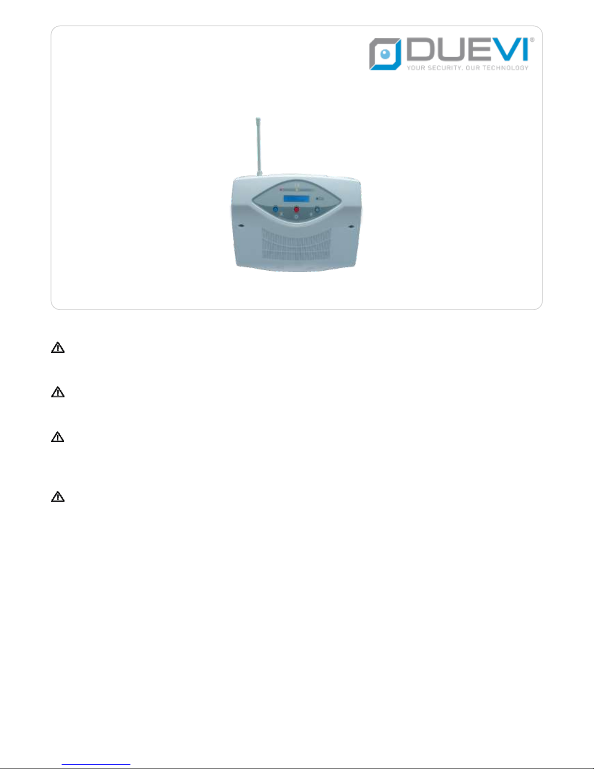
CE60-8GSM/CE60-8
Wireless/wired bi-directional Control Panel
[AN] [SPV] [48 bit] [Series 100] TECHNICAL MANUAL 16.02-MT:1.1-H:x.x-F:1.0.3-S:1.0.3
Page 2

2
SAFETY TIPS AND MAINTENANCE
BEFORE TURING ON THE CONTROL PANEL, MAKE SURE THE POWER LINE IS SUITABLE AS INDICATED ON PRODUCT
LABEL OR IN THIS MANUAL.
THE ELECTRICAL SYSTEM USED TO CONNECT THE CONTROL PANEL NEEDS TO HAVE A BIPOLAR BREAKER SWITCH
THAT IS EASILY ACCESSIBLE.
DO NOT INSTALL IN HUMID, HOT ENVIRONMENTS OR CLOSE TO BATHTUBS, SINKS, ETC.
COMMUNICATION BETWEEN THE VARIOUS COMPONENTS OF THE SYSTEM ARE THOUGH RADIOFREQUENCY.
BEFORE FINAL INSTALLATION, BE SURE THAT PANEL COMMUNICATES CORRECTLY WITH ALL THE DEVICES. COULD
HAPPEN THAT THE UNIT DOES NOT RECEIVE SIGNALS FROM SOME SENSOR. THIS IS DUE TO THE ENVIRONMENT IN
WHICH THE SYSTEM OPERATES: REINFORCED CONCRETE WALLS, METAL BOXES, METAL SHELVES, ETC. MAY CAUSE
PARTICULAR CONDITIONS OF REFRACTION OR REDUCTION OF SIGNALS (AS THE CONNECTION LOST OF MOBILE
PHONE NETWORK).
TO AVOID THESE PROBLEMS AND ALWAYS GET MAXIMUM PERFORMANCE FROM YOUR SYSTEM, REMEMBER TO
ALWAYS RUN SOME PRELIMINARY TESTS ON THE POSITIONING, IN ORDER TO DETERMINE THE EFFECTTIVENESS
OF THE RADIO TRANSMISSIONS.
THE COMPANY SHALL NOT BE LIABLE FOR ANY IMPROPER USE OF THE PRODUCT, INCORRECT INSTALLATION OR
FAILURE TO COMPLY WITH INSTURCTIONS OF THIS MANUAL AND THE LAW REGARDING ELECTRICAL SYSTEMS.
Page 3

3
INDEX
1. TECHNICAL DATA ...................................................................................................................................................................................................... 6
2. CONTROL PANEL ELECTRONIC BOARD ...................................................................................................................................................................... 8
2.1. CONNECTORS ................................................................................................................................................................................................ 8
2.2. JUMPERS ....................................................................................................................................................................................................... 8
2.3. DIP-SWITCH ................................................................................................................................................................................................... 9
2.4. TERMINALS .................................................................................................................................................................................................... 9
2.5. SWITCH ....................................................................................................................................................................................................... 10
2.6. MICROPHONE .............................................................................................................................................................................................. 10
2.7. GSM MODULE ............................................................................................................................................................................................. 10
2.8. USB CONNECTORS ....................................................................................................................................................................................... 10
3. INSTALLATION ....................................................................................................................................................................................................... 11
3.1. WHERE TO PLACE THE CONTROL PANEL ....................................................................................................................................................... 11
3.2. SIM CARD .................................................................................................................................................................................................... 11
3.3. OPEN THE FRONT PANEL .............................................................................................................................................................................. 12
MAINTENANCE (AVOID TAMPER ALARM) .................................................................................................................................................................... 12
3.4. WALL INSTALLATION .................................................................................................................................................................................... 12
3.5. WIRED ZONES CONNECTION ........................................................................................................................................................................ 13
3.6. TECHNOLOGIC ZONES .................................................................................................................................................................................. 13
3.7. TRANSPONDER KEY READER CONNECTION ................................................................................................................................................... 14
3.8. ARMING HARDWARE KEY ............................................................................................................................................................................. 14
3.9. TEMPERATURE PROBE (MOD. TEMP, OPTIONAL) .......................................................................................................................................... 15
3.10. ANTI-JAMMING (GSM BLINDING PROTECTION) ........................................................................................................................................... 15
3.11. AUDIO TERMINALS OF THE PANEL ................................................................................................................................................................ 16
3.12. ARMING STATUS SIGNALLING CONNECTION ................................................................................................................................................ 16
3.13. 230 VAC POWER LINE CONNECTION .............................................................................................................................................................. 17
3.14. INT1 – EMERGENCY SWITCH ........................................................................................................................................................................ 17
3.15. FRONT PANEL: DISPLAY AND BUTTONS......................................................................................................................................................... 17
4. ENABLE/DISABLE THE RADIO TRANSMISSION ........................................................................................................................................................ 18
4.1. ENABLE THE RADIO TRANSMISSION ............................................................................................................................................................. 18
4.2. DISABLE THE RADIO TRANSMISSION ............................................................................................................................................................ 18
5. ACCESS TO INSTALLER MENU................................................................................................................................................................................. 19
5.1. ENTER IN INSTALLER MENU ......................................................................................................................................................................... 19
5.2. EXIT FROM INSTALLER MENU ....................................................................................................................................................................... 19
5.3. INSTALLER MENU ........................................................................................................................................................................................ 20
Page 4

4
6. CLEAR THE CONTROL PANEL MEMORY ................................................................................................................................................................... 21
7. LEARN ACTIVATORS ................................................................................................................................................................................................ 22
8. LEARN WIRELESS ZONES ........................................................................................................................................................................................ 23
8.1. LEARN BY TAMPER CODE .............................................................................................................................................................................. 24
8.2. LEARN BY DETECTION CODE ......................................................................................................................................................................... 25
8.3. VOICE ALERT FROM WIRELESS ZONES 1 ÷ 30 ................................................................................................................................................ 25
9. BI-DIRECTIONAL DEVICES ....................................................................................................................................................................................... 26
9.1. ADD A RADIO SYSTEM STATUS VISUALIZER (STIMPIA-9) ................................................................................................................................. 26
9.2. ADD A WIRELESS KEYBOARD (DVTR-RT, DVT-TOUCH) .................................................................................................................................... 26
9.3. ADD A WIRELESS SIREN (SIRRB-NT, SIRR-AC) ............................................................................................................................................... 27
9.4. ADD A WIRELESS SIREN (VV-ZELA-RA, VV-ZELA-RB) ........................................................................................................................................ 27
9.5. ADD A WIRELESS KEYBOARD WITH DISPLAY (DVT-R-OLED) ............................................................................................................................ 28
9.6. ADD A RADIO TRANSPONDER READER (LET-PROX-W) .................................................................................................................................... 28
9.7. DELETE A BI-DIRECTIONAL DEVICE ................................................................................................................................................................ 28
10. PANEL TEST ........................................................................................................................................................................................................... 29
10.1. “RADIO LEVEL” TOOL .................................................................................................................................................................................... 29
11. PROGRAM THE RELAY OUTPUTS (AUX1, AUX2, AUX3) .............................................................................................................................................. 29
12. FUNCTIONS (INSTALLER MENU) ............................................................................................................................................................................ 31
12.1. LANGUAGE .................................................................................................................................................................................................. 31
12.2. DATE AND TIME ............................................................................................................................................................................................ 31
12.3. POWER FAIL TIME ........................................................................................................................................................................................ 31
12.4. DIALLER CODE .............................................................................................................................................................................................. 31
12.5. LEARN ACTIVATORS ...................................................................................................................................................................................... 31
12.6. TX RADIO CODE ............................................................................................................................................................................................ 32
12.7. LEARN BI-DIRECTIONAL DEVICES .................................................................................................................................................................. 32
12.8. WIRELESS SIREN TEST .................................................................................................................................................................................. 32
12.9. LEARN WIRELESS ZONES .............................................................................................................................................................................. 32
12.10. ARMING PROGRAMS............................................................................................................................................................................... 33
12.11. ALERT ...................................................................................................................................................................................................... 33
12.12. EXIT TIME ................................................................................................................................................................................................ 33
12.13. ENTRY TIME............................................................................................................................................................................................. 33
12.14. PRE-ALARM TIME .................................................................................................................................................................................... 33
12.15. EXTERNAL/OUTDOOR ALERT .................................................................................................................................................................... 34
12.16. VOICE MESSAGES .................................................................................................................................................................................... 34
12.17. ARM/DISARM BEEP ................................................................................................................................................................................. 35
12.18. RADIO BLINDING .................................................................................................................................................................................... 35
Page 5

5
12.19. DOOR CONTROL ...................................................................................................................................................................................... 35
12.20. SUPERVISION .......................................................................................................................................................................................... 35
12.21. VOICE CALL NUMBER .............................................................................................................................................................................. 35
12.22. RELAY AUX (AUX1, AUX2, AUX3) ................................................................................................................................................................ 36
12.23. RADIO SATURATION ................................................................................................................................................................................. 36
12.24. RADIO ZONE TEST .................................................................................................................................................................................... 36
12.25. GSM TEST ............................................................................................................................................................................................... 36
12.26. GPRS CONTACT ID TEST ........................................................................................................................................................................... 37
12.27. DELETE TELEPHONE NUMBERS ............................................................................................................................................................... 37
12.28. RESET ...................................................................................................................................................................................................... 37
13. PROGRAM THE GSM COMMUNICATOR .................................................................................................................................................................. 38
13.1. PROGRAM TELEPHONE NUMBERS ............................................................................................................................................................... 38
13.2. REMOTE CODE ............................................................................................................................................................................................. 39
13.3. COMMAND SMS .......................................................................................................................................................................................... 39
13.4. ADD TELEPHONE NUMBERS ......................................................................................................................................................................... 41
13.5. DELETE TELEPHONE NUMBERS .................................................................................................................................................................... 41
13.6. EMERGENCY NUMBERS ............................................................................................................................................................................... 41
13.7. PROGRAM SIM CREDIT REQUEST ................................................................................................................................................................. 42
13.8. SIM CREDIT REQUEST ................................................................................................................................................................................... 42
13.9. SET THE ALERT FOR SIM EXPIRING ................................................................................................................................................................ 42
13.10. GENERAL NOTES ON COMMAND SMS .................................................................................................................................................... 43
13.11. SMS CREATION SYNTAX ........................................................................................................................................................................... 44
14. VOICE MENU ......................................................................................................................................................................................................... 46
15. POWER SIGNALLINGS ............................................................................................................................................................................................ 47
16. OPENED DOOR SIGNALLING .................................................................................................................................................................................. 48
16.1. WHEN THE FUNCTION IS DISABLED .............................................................................................................................................................. 48
16.2. WHEN THE FUNCTION IS ENABLED .............................................................................................................................................................. 48
17. CONTACT ID ........................................................................................................................................................................................................... 49
18. RADIO BLINDING AND RADIO SATURATION ............................................................................................................................................................ 50
18.1. RADIO BLINDING ......................................................................................................................................................................................... 50
18.2. RADIO SATURATION TEST ............................................................................................................................................................................. 50
Page 6

6
1. TECHNICAL DATA
WIRELESS ZONES
60 wireless zones
WIRED ZONES
8 wired zones Normally Closed *
TAMPER
1 tamper input line (24 h/24) **
ARMING TYPES
Total
Partial
External/Outdoor
RADIO CODE
Custom code, 48 bit
RADIO FREQUENCY
RX + TX: 433,92 MHz (with anti-blinding)
RADIO RANGE
100 m (open field)
ACTIVATORS
16 wired/wireless activators
ARMING CONTROLS
Remote controls (TXS/M, TXS4, TX4)
Wireless keyboards (DVTR-RT, DVT-Touch, DVT-R-OLED)
Transponder keys (LET or LET-PROX-W + CHT2)
Mechanical key (NCI input)
GSM (SMS, voice menu)
ALARM LOG
100 alarm events with identification of zone, armings and SMS sending
TEMPERATURE PROBE (optional)
Temperature sensor (optional) for “temperature control” function ***
DISPLAY
System status visualization, GSM signal level, date and time, radio level, battery
status, functions, Installer and User menu
INTERNAL SIREN
Magneto-dynamic siren, high power (115 dB)
ACOUSTIC SIGNALLINGS
ALERT:
tone
voice (from the first 30 wireless zones, only with AMP audio module)
Warning tones
WIRED OUtPUTS FOR EXTERNAL DEVICE
CONTROL
n. 1 alarm relay, dry-contact type
n. 1 12 VDC output (drop-down in alarm)
n. 1 12 VDC output (raise-up in alarm)
n. 3 programmable outputs (n. 1 dry-contact relay, n. 2 OptoMOS outputs)
WIRED OUTPUTS FOR EXTERNAL DEVICE
POWERING
n. 1 12 VDC / max 1 A for sirens/communicators
ALARM DURATION
Custom: from 10 to 240 seconds
MAX ALARM NUMBER
MAX 4 alarms per sensor during the same arming
(total MAX 10 alarms)
DELAYS
Programmable Input and Output
POWER
230 VAC / 50 Hz
ABSORPTION
Stand-by: MAX 30 mA
Alarm: MAX: 110 mA
WORKING TEMPERATURE
-15 °C ÷ +45 °C
BACKUP BATTERY
12 V MAX 7 Ah
DIMENSION (L x H x W)
330 x 250 x 90 [mm] (excluded antenna)
Page 7

7
INTEGRATED GSM COMMUNICATOR
n. 8 telephone numbers
SMS for: alarm, panic and silent alarm, power status,arming status,
supervision
Voice calls for: alarme, panic, silent alarm
Voice menu
CONTACT-ID
Standard DC09 (up to two monitoring stations)
PROGRAMMING
Installer Menu
Software COMCE608
* Referred to GND. If not used/disabled, close always to GND
** Referred to GND
*** The temperature probe (mod. TEMP, optional) must be connected to CN.TEMP terminal
THE CE 60-8 GSM WORKS ONLY WITH THE “SERIES 100” DEVICE TYPE
Page 8
8
2. CONTROL PANEL ELECTRONIC BOARD
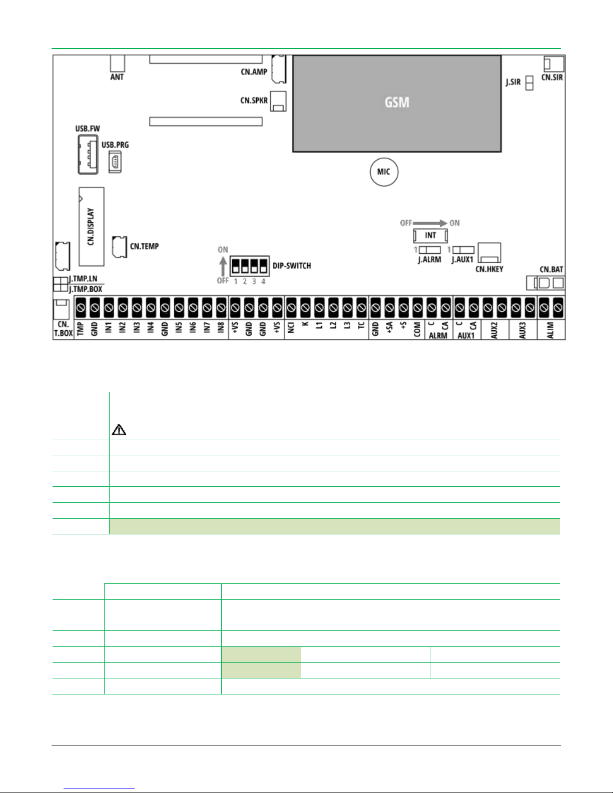
2.1. CONNECTORS
CN.T.BOX
Anti-removal and anti-opening tamper switch connectors
CN.DISPLAY
Front panel (display and keyboard) connector
Plug/unplug only with control panel without power source!
CN.AMP
Audio output for Voice Alert. For the use, connect the external audio module mod. AMP (optional)
CN.SPKR
On-board speaker: use the speaker only for voice messages recording
CN.SIR
On-board magneto-dynamic siren connector
CN.TEMP
Temperature probe (optional) – Device cod. TEMP
CN.BAT
Backup battery connector (12 V / max 7 Ah) – This connector provide battery charge
CN.HKEY
NOT USED
2.2. JUMPERS
OPENED
CLOSED
J.TMP.LN
Tamper
(wired line, TMP terminal)
Enabled
Disabled
J.TMP.BOX
Internal Tamper
Enabled
Disabled
J.ALRM
ALRM output relay mode
Not used
1-2: Normally Closed
2-3: Normally Opened
J.AUX1
AUX1 output relay mode
Not used
1-2: Normally Closed
2-3: Normally Opened
J.SIR
Internal siren power
LOW
HIGH
Page 9
9
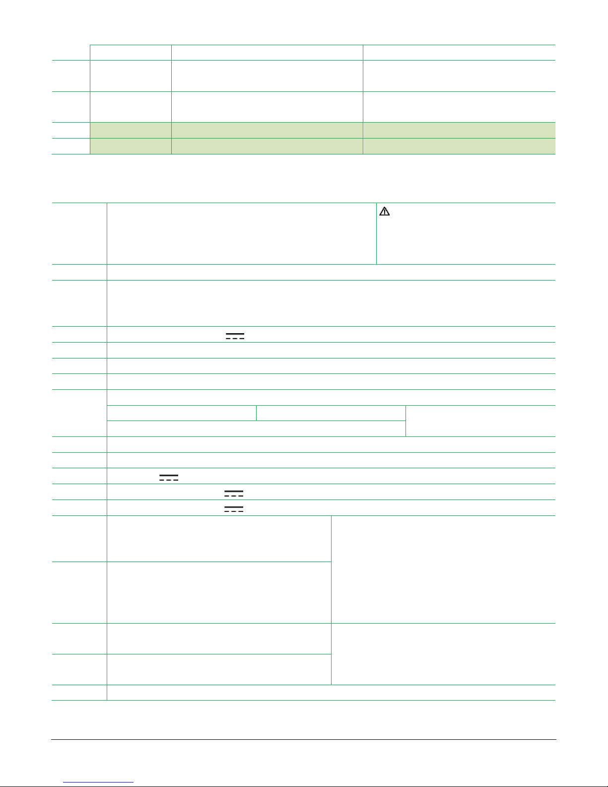
2.3. DIP-SWITCH
ON
OFF
DIP1
Event log
Vengono mostrati gli ultimi 100 eventi
Per scorrere la coda eventi premere il tasto “O”
Normal working
DIP2
Installer Menu
Programmazione Installatore (vedere il paragrafo
“ACCESS TO INSTALLER MENU”)
Normal working
DIP3
NOT USED – LEAVE OFF
DIP4
NOT USED – LEAVE OFF
2.4. TERMINALS
TMP
Tamper line terminals, Normally Closed (NC)
Closed to GND = normal status
Opened = Wired Tamper Alarm
If the tamper line is not used, close the jumper J.TMP.LN
The tamper protection is always active
(24h/24, even at system disarmed).
To open the cover of the control panel without
alarm: disarm and open within 2 minutes
GND
Ground reference (negative) for signals and powers
IN1
…
IN8
Wired zone inputs , Normally Closed (NC)
Closed to GND = normal status ― Opened = Alarm
Connect to GND even if not used or disabled
+VS
Zones power line, positive +12 V / max 200 mA
GND
Gorund reference (negative)
NCI
Input for hardware key: system disarmed (at rest) when closed to GND; system armed when opened or wire-cut
K
Data input/output line for transponder key reader
L1
L2
L3
Signalling outputs (combined to LEDs on front panel):
L1 = Total / Alarm
L2 = Partial / Opened Doors
L3 = AC pwer line 230 VAC
L1 + L2 = External/Outdoor
TC
System status output: GND when system armed, +12V at system disarmed
GND
Ground reference (negative)
+SA
Positive +12 V for external siren or dialler powering (300 mA MAX)
+S
Alarm command (positive +12 V raise-up in alarm)
COM
Alarm command (positive +12 V drop-down in alarm)
ALRM
ALARM RELAY (dry contact):
C = common terminal, CA = output terminal
(programmable NC or NO with J.ALRM)
Relay info:
Contact impedance: 100 mΩ max (@ 6 V
DC
/ 1 A)
Max voltage: 120 V
AC
/ 24 VDC
Max current: 1 A
Switching speed: 4 ms
AUX 1
PROGRAMMABLE RELAY 1 (dry contact):
C = common terminal, CA = output terminal
(programmable via Installer menu or software)
(programmable NC or NO with J.AUX1)
AUX 2
PROGRAMMABLE RELAY 2
Programmable outputs info:
OptoMOS (Normally Closed)
programmable via Installer menu or software
max 40 V
DC
/ 100 mA
AUX 3
PROGRAMMABLE RELAY 3
ALIM
Terminals for connection to secondary output of main power transformer
Page 10
10
2.5. SWITCH
INT1
Activation / standby of
the control panel
ON
OFF
Control panel active (normal working)
Control panel in standby
Warning: when the panel is in standby,
the power supply to terminals is
maintained!
2.6. MICROPHONE
MIC
Microphone for voice messages recording and environment listening
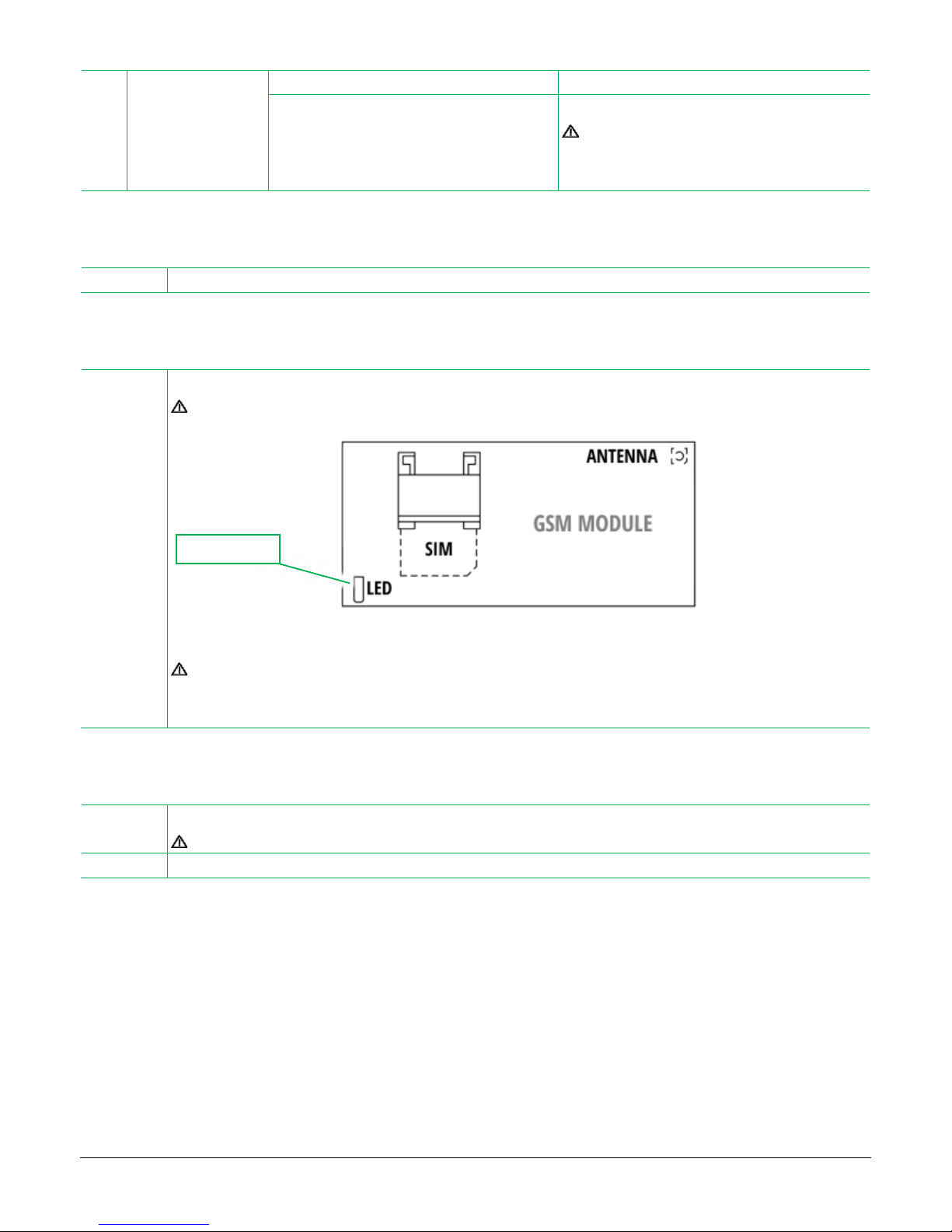
2.7. GSM MODULE
GSM
GSM module modem
Insert/extract the SIM card only at control panel completely powered off!
It is possible – if not used – to remove the GSM module from the panel.
Connect/remove the GSM module only at control panel completely powered off!
The control panel automatically detects the absence of the GSM module and disables all GSM functions and Modem
Menu.
2.8. USB CONNECTORS
USB.PRG
USB connection for control panel programming via software
The control panel automatically enters in programming mode as it is connected to PC
USB.FW
USB connection for control panel firmware upgrade
GSM activity
Page 11
11
3. INSTALLATION
3.1. WHERE TO PLACE THE CONTROL PANEL
Install the control panel in the best place according to:
easiness to access by the user (ex. for wall mounting, command managing, display sight, standard maintenance etc.)
easiness and availability to connections (ex. power line or other wired devices, etc.)
protected by tamper attempting (ex.: hard to find the control panel, area protected by PIRs)
wireless communication to devices (remote controls, sensors, sirens and accessories)
To verify the wireless range there are two options:
“Panel Test” (activated at system disarmed)
“Sensors Test” (inside Installer Menu)
Perform these tests placing temporary the control panel (powered with battery) and the wireless devices (already learned in panel)
in their installation points and verify if the control panel receives the wireless codes.
In case the radio communication fails for one or more device, it is necessary to change the installation point of the panel and/or
devices.
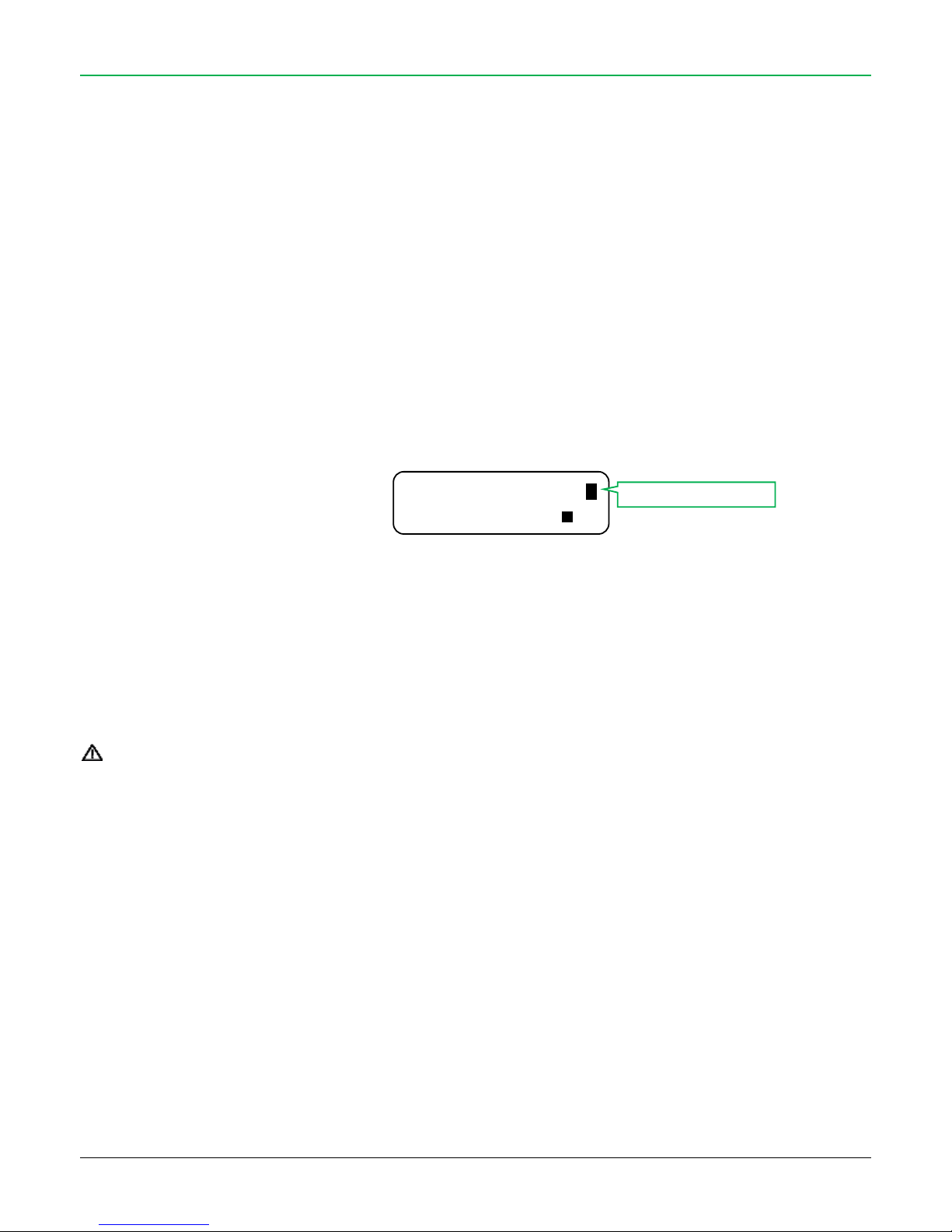
The display shows the wireless signal level received in real time, in this way it is possible to see if there are unwanted radio
transmissions in the environment:
GSM field
Holding down the “O” button at system disarmed, the GSM Menu opens. In this menu it is visualized the provider name and the
GSM signal level available.
In case the signal level is too low or absent, it is necessary to change the installation point of the control panel or it is possible to
connect an external GSM antenna in place of the original one.
3.2. SIM CARD
INSERT/REMOVE THE SIM CARD ONLY WHIT THE CONTROL PANEL COMPLETELY OFF (NO PWERLINE OR BATTERY)
The GSM module of the panel can works with these SIM card types:
Connection: GSM/GPRS (no UMTS)
SIM: “Voice + data” or data only (M2M)
Crdit: rechargeable or contract
SIM size: normal (miniSIM and microSIM only with adapter)
Before insert the SIM card verify:
The PIN code is disabled.
To verify and disable the PIN code: insert the SIM in a mobile phone, verify there is no PIN request and, if necessary, disable the
PIN request using the mobile phone menu
DISABLE all the services active on SIM (example: call forwarding, auto-answering, etc).
To verify and disable the services: insert the SIM in a mobile phone and call the service number:
##002# (valid for all network providers)
As answer, there will come a confirm message “Deviations disabled” (the visualization varies depending on the mobile phone used).
Delete from SIM all data (example: received messages, contact list…)
14:51 10/11/15 _
Disarmed _ X
Radio signal level
Page 12
12
3.3. OPEN THE FRONT PANEL
MAINTENANCE (AVOID TAMPER ALARM)
The tamper protection is active 24h/24 (at system armed/disarmed). To open the control panel, the TMP line or a wireless device without
TAMPER alarm:
Disarm the panel (even if already disarmed) and wait confirm (a long “beep”)
For 2 minutes the system DISABLE the TAMPER alarm: perform the intervention or, if necessary, exclude the tamper of
the panel by closing the jumper J.TMP.BOX and/or J.TMP.LN. It is also possible to switch off the panel by setting INT1 = OFF
After maintenance, close the cover within 2 minutes from opening of J.TMP.BOX and/or J.TMP.LN or from INT1 = ON
3.4. WALL INSTALLATION
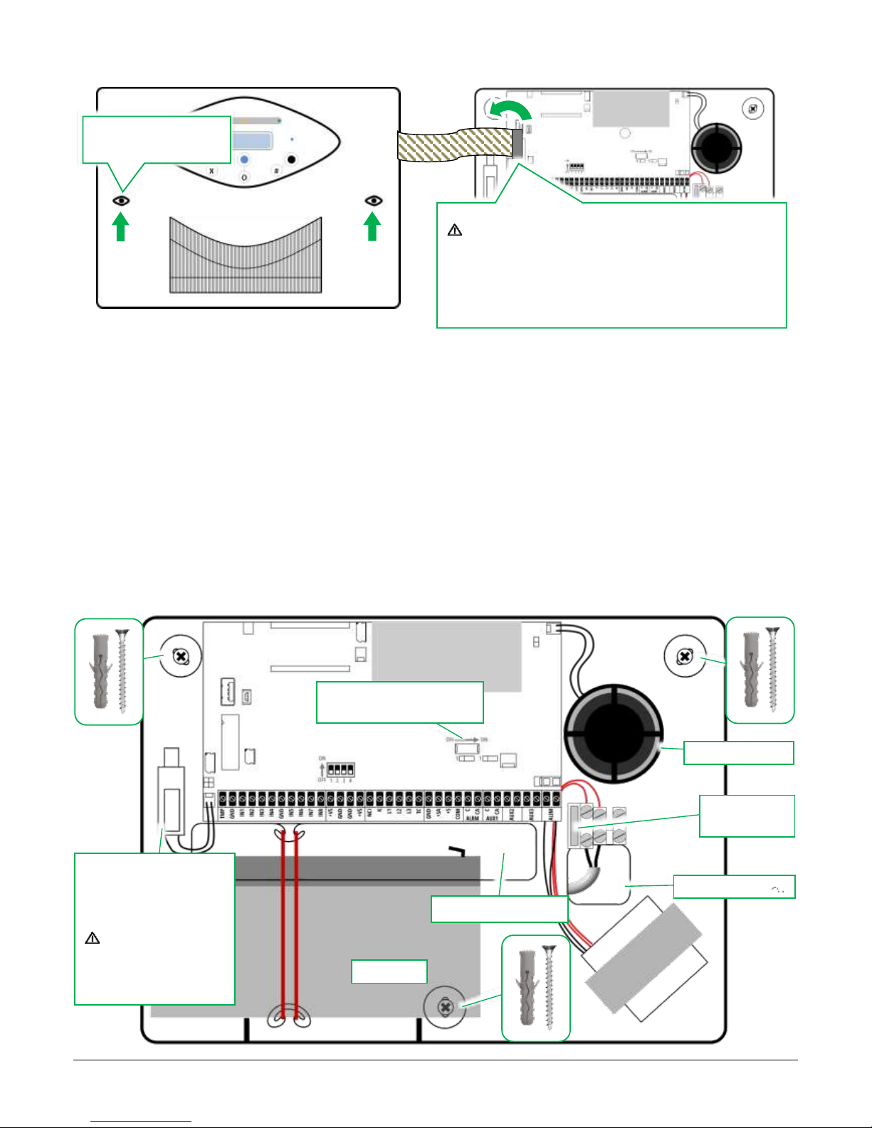
The main frame is provided with three wall anchor points: fix the bottom of the panel to the wall using three dowels.
The display and buttons on the front panel are connected
to the electronic board with a communication cable!
Unplug temporarily the connector of the cable from the
electronic board and perform all the fixing operations.
Restore the connection before power on the control panel.
Remove the two screws
of the cover
BATTERY
CABLE PATH
AC POWER 230 V
FUSE
250 V T200MA
INT1
EMERGENCY SWITCH
ANTI-OPENING / ANTIREMOVAL TAMPER
CONTROL THE ANTI-
REMOVAL TAMPER SWITCH
LEANS TO THE WALL
INTERNAL SIREN
Page 13
13
3.5. WIRED ZONES CONNECTION
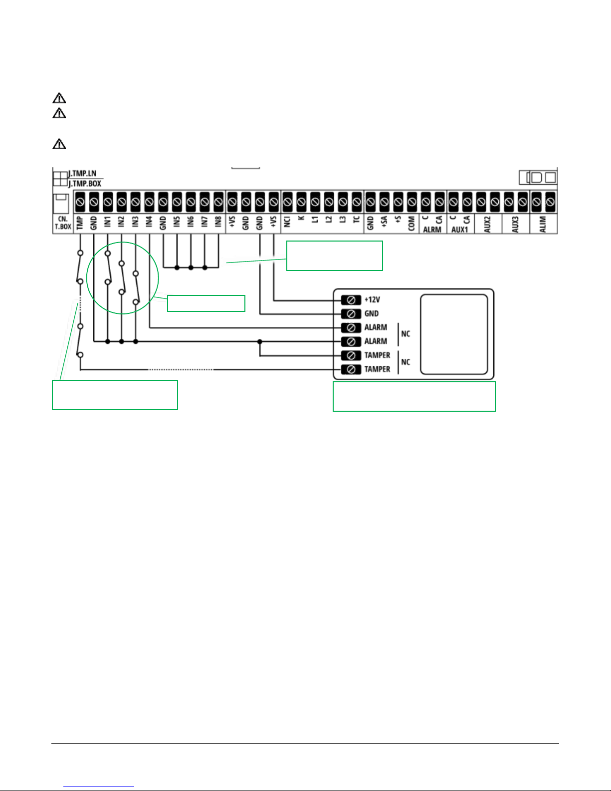
PERFORM ALL CONNECTION ONLY WITH CONTROL PANEL COMPLETELY POWERED OFF (NO AC POWER, NO BATTERY)
Close the zone inputs IN1 ÷ IN8 not used to GND
During installation and maintenance, exclude the tamper protection (anti-opening / anti-removal) closing the jumper J.TMP.BOX
(remember to re-enable it at the end of intervention)
If the wired tamper line TMP is used, it’s mandatory to open the jumper J.TMP.LN
3.6. TECHNOLOGIC ZONES
All the wired and wireless zones con be set as “technologic”.
This type of zone is 24h/24 active independently if the the panel is armed or not: it is used for technologic sensors like smoke sensors (code
DSF), flood sensors (code DSA), etc..
It is possible to set the zone as “technologic” via programming software.
The relay outputs AUX1 ÷ AUX 3 can be combined to “Technologic” event in order to activate them in case of detection of this type of zone.
It is possible to enable / disable the siren sound in case of “technologic” detections (via software).
Not used wired
inputs (close to GND)
Example: connection of a wired sensor:
alarm, power and tamper
NC zone contacts
TAMPER line: connect the NC
tamper outputs in series
Page 14
14
3.7. TRANSPONDER KEY READER CONNECTION
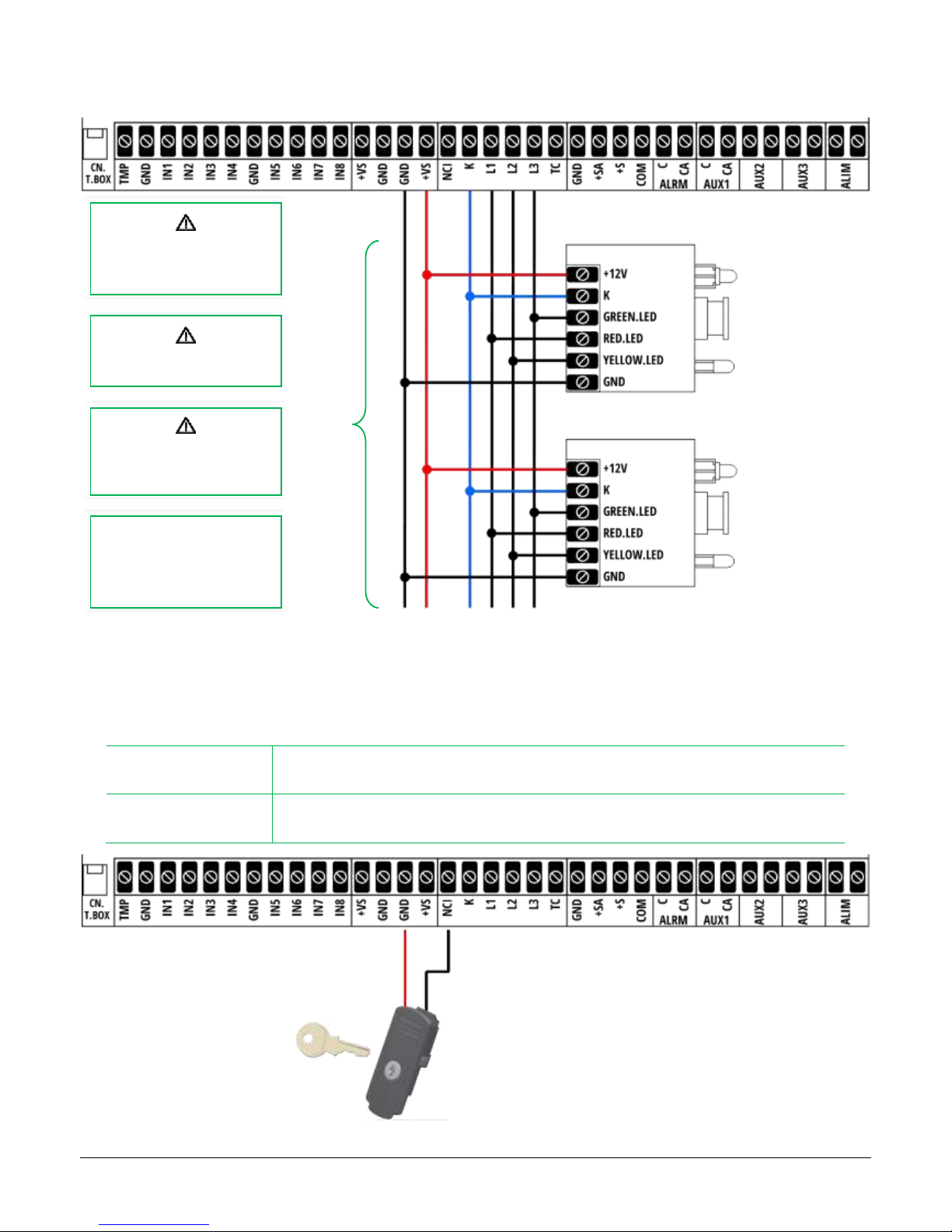
Connect the transponder key readers (mod. LET-MONO) according to the following scheme:
3.8. ARMING HARDWARE KEY
The NCI terminal (Normally Closed: Armed) is an input useful to arm/disarm the control panel by wire (example: with an hardware key or
through domotic interface).
NCI = OPENED
Control panel armed in TOTAL MODE
When the STI input switch from GND to “opened”, the control panel is armed in TOTAL mode
NCI = GND
Control panel DISARMED
When the STI input switch from “opened” to GND, the control panel is disarmed
It is possible to connect up
to 3 key readers
(parallel connection)
Max distance reachable
is 100 meters
The readers are
automatically activated as
they are connected
To learn the transponder
keys:
Installer Menu > “Activator
learning”
Page 15
15
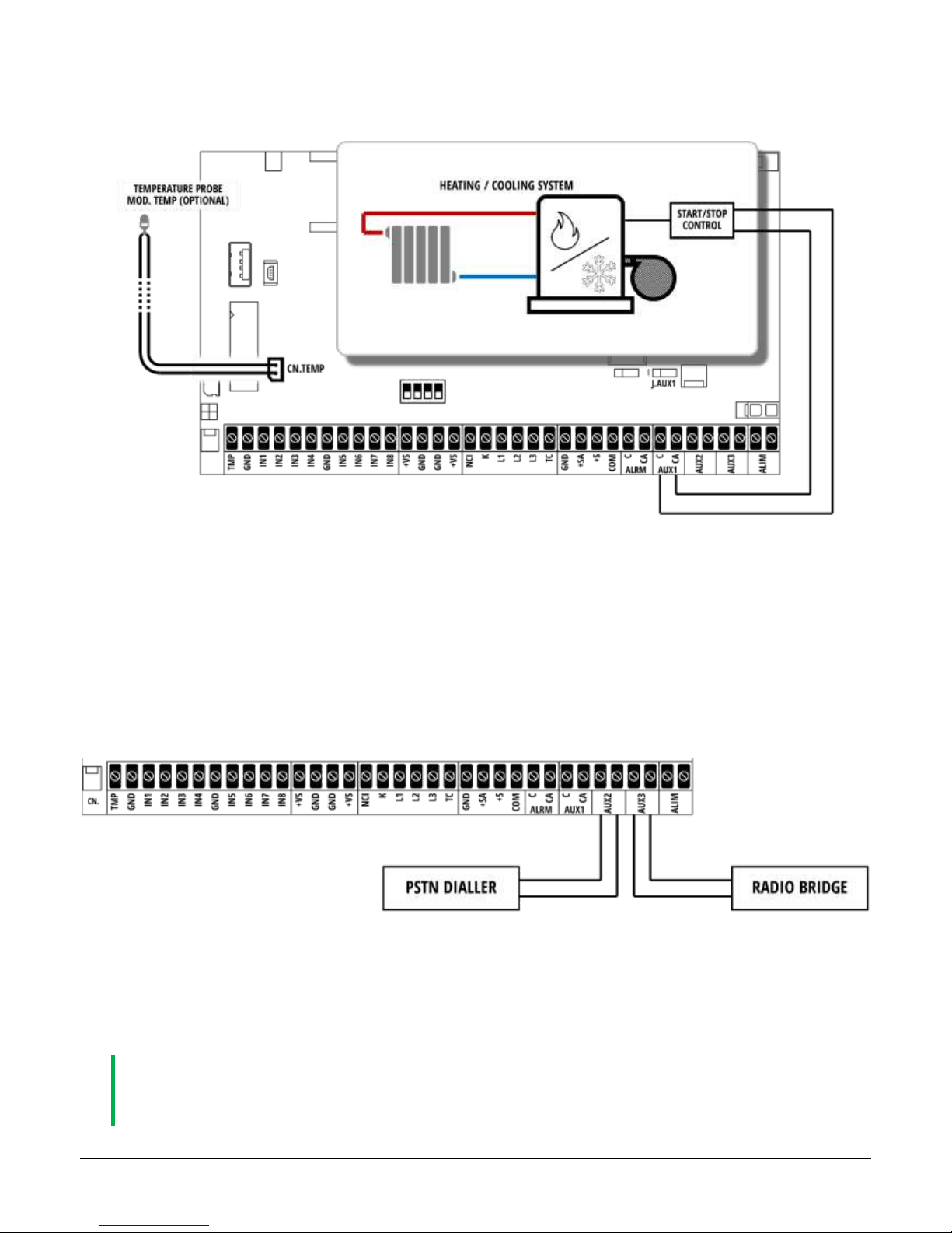
3.9. TEMPERATURE PROBE (MOD. TEMP, OPTIONAL)
The control panel can be equipped with a temperature probe, to be connected to CN.TEMP connector.
Program a relay output for the “temperature” event and connect properly the heating system to control.
For the woring of the “temperature” function, read the dedicated paragraph.
3.10. ANTI-JAMMING (GSM BLINDING PROTECTION)
The control panel is capable to detect if the GSM module cannot establish a connection with the network provider due to GSM signal
jamming.
Program one (or more) relay output AUX1, …, AUX3 for the “JAM” event (active in case of GSM network jamming) and connect to an
alternative communication system (example: external PSTN module, radio bridge…) to receive alerts.
If the GSM module detects a jamming attempt over the GSM communication frequencies, the programmed relay output switches (the AUX1
relay can be set N.C. or N.O. using J.AUX1):
The signalling starts after about 20 seconds from the beginning of the noise: the relay output activates.
The output backs to normal state after about 30 seconds from the end of the noise: the relay output backs to rest.
IN CASE OF GSM NETWORK FAILURE (EXAMPLE: THE PROVIDER IS TEMPORARY UNAVAILABLE, THE PANEL IS
INSTALLED IN A PLACE WITH WEAK GSM SIGNAL…) THE ANTI-JAMMING DOES NOT SIGNAL JAMMING, THE
PROGRAMMED OUTPUT STAY AT REST.
Page 16
16
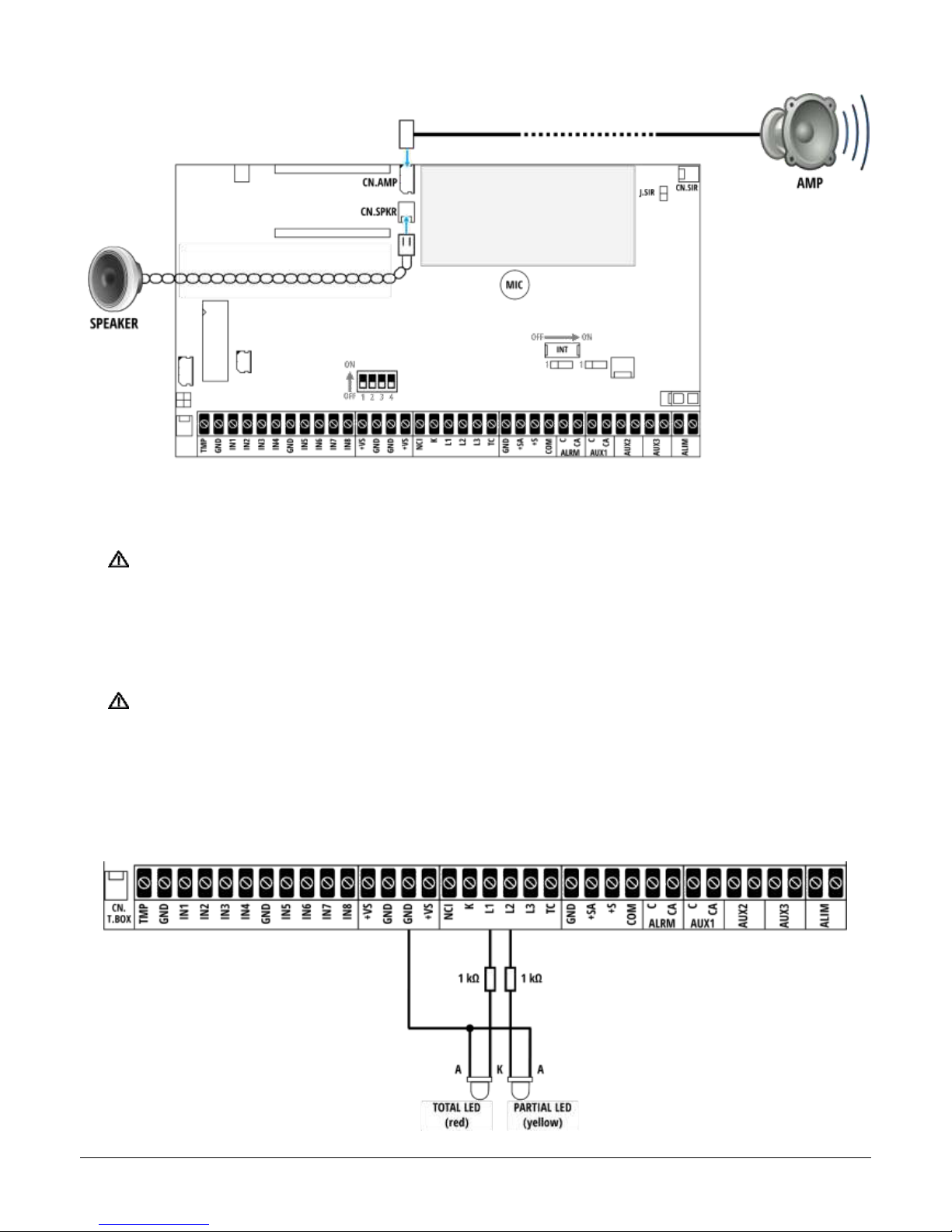
3.11. AUDIO TERMINALS OF THE PANEL
On control panel there are two audio outputs:
CN.SPKR: internal speaker. The internal speaker allows to listen the voice messages during editing (useful for example when
recording customized voice messages).
WHEN THE CUSTOMIZATION OF THE VOICE MESSAGES ENDS, ALWAYS
DISCONNECT THE SPEAKER FROM THE CN.SPKR TERMINAL!
CN.AMP: external audio output. This audio output play the Voice Alert messages (wireless zones 1 ÷ 30) and the system
arming/disarming status of the control panel (if enabled, via software).
TO USE THIS OUTPUT IT IS NECESSARY TO CONNECT THE EXTERNAL AMPLIFIED MODULE MOD. AMP
(OPTIONAL)
3.12. ARMING STATUS SIGNALLING CONNECTION
It is possible to connect external LEDs to visualize the system status in addition to the LEDs on front panel.
Page 17
17
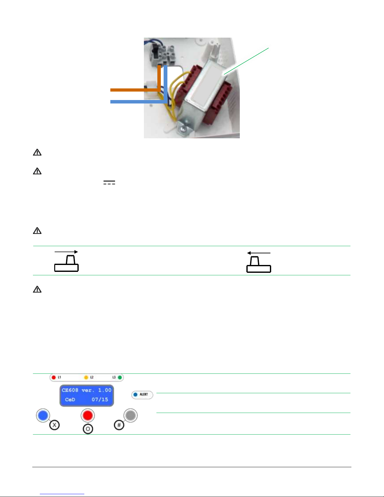
3.13. 230 V
AC
POWER LINE CONNECTION
Provide power line 230 VAC
Connect the battery to red and black cables of the CN.BAT connector (red wire = positive pole “+”; black wire = negative pole “-“)
The battery must be 12 V rechargeable lead type.
The battery allows the control panel to maintain working the system in case of main power line failure.
3.14. INT1 – EMERGENCY SWITCH
Before activate the control panel, perform all wired connections to the alarm system!
PANEL ACTIVE
PANEL OFF
FROM THE MOMENT INT1 IS SET TO ON, THE SYSTEM REQUIRES ABOUT 5 SECONDS TO BOOT.
DURING THIS TIME THE DISPLAY STAYS OFF.
INT1 may be considered as emergency switch: when set to OFF the control panel is deactivated but maintaining power and reference voltages
on all its outputs for the peripherals.
3.15. FRONT PANEL: DISPLAY AND BUTTONS
Button X
Quick: enble/disable Alert
Hold 2 seconds (within 60 s from disarming): User Menu
Button O
Quick: visualize the “Alarm Memory”
Hold 2 seconds: visualize GSM Modem Menu
Button #
Quick: visualize the control panel version
Hold 2 seconds (within 30 s from last receving): GSM Dialler Test
TRANSFORMER:
Primary: 230 VAC – 50/60 Hz – 16 VA
Secondary: 14,7 VAC – 1,26 A
LIVE
NEUTRAL
OFF
ON
OFF
ON
Page 18

18
4. ENABLE/DISABLE THE RADIO TRANSMISSION
FACTORY SETTING: THE CONTROL PANEL HAS THE RADIO TRANSMISSION DISABLED!
It is necessary to enable the control panel radio transmission when one or more of these device are used:
Wireless sirens (SIRRB-NT, SIRRA-NT, VV-ZELA-RA, VV-ZELA-RB)
Bi-directional devices (DVTR-RT, DVT-TOUCH, DVT-R-OLED, STIMPIA-9, SINT-13, VOCALIST, LET-PROX-W)
To enable the radio transmission of the panel change the TX Radio code (via Installer menu or software). The TX Radio code can be seen
as a radio “channel”.
Sirens and radio devices “tune” automatically to TX Radio of the panel during the learning procedure.
This allow to:
distinguish the radio transmissions of different panels (near) avoiding interferences
send commands from different panels to the same sounder or radio device
The radio codes that the panel transmits are:
Armings (Total, Partial, External) and Disarming
Alarm and End Alarm
Tamper
Maintenance and End Maintenance
4.1. ENABLE THE RADIO TRANSMISSION
enter in Installer menu (see next paragraph)
select the “TX Radio Code” option
insert any value different than zero (from 001 to 999)
exit Installer menu
Note: if the TX Radio value is changed AFTER the learning of sounders and bi-directional devices, these will not communicate with the panel
anymore. It is necessary to delete all the devices and learn again them.
4.2. DISABLE THE RADIO TRANSMISSION
enter in Installer menu (see next paragraph)
select the “TX Radio Code” option
insert the value “000” (zero)
exit Installer menu
Note: switching off the radio transmission will reduce the number of operations the panel has to execute, thus increasing its reactivity
Page 19
19
5. ACCESS TO INSTALLER MENU
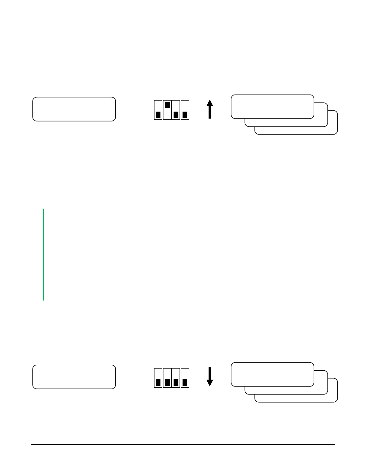
5.1. ENTER IN INSTALLER MENU
Disarm the control panel (even if already disarmed)
Open the cover of the control panel (pay attention to the connection cable between control panel and the cover!)
Set DIP2 to ON: the control panel shows on display the first Installer Menu item
It is possible to change the settings of the control panel using the “X”, “O” and “#” buttons on the front panel:
To go forward in menu, press and release the “#” button, to go backward press long and release the “#” button
To change the values use the “O” and “X” buttons
MAINTENANCE
IF THE RADIO TRANSMISSION OF THE PANEL IS ENABLED (TX RADIO CODE DIFFERENT FROM 000):
• WHEN DIP-2 IS SET TO ON, THE PANEL SENDS A “MAINTENANCE” RADIO CODE.
IF THE PANEL IS STORED IN SOUNDER, THIS ONE WILL EMIT A “BEEP” AND BLINK: NOW IT IS POSSIBLE TO OPEN
THE COVER WITHOUT GENERATE TAMPER ALARM.
• WHEN DIP-2 IS SET TO OFF, THE PANEL SENDS A “END MAINTENANCE” RADIO CODE.
THE SOUNDER ENABLE ITS TAMPER CONTROL (WILL EMIT A “BEEP” AND BLINK).
THESE CODES HAS NO EFFECT ON BI-DIRECTIONAL DEVICES.
5.2. EXIT FROM INSTALLER MENU
To exit from Installer Menu, set DIP2 to OFF at any time.
All the changes are saved and used immediately.
ON
2
OFF 1 3
4
12:30 01/02/12 ▄
Disarmed ▄ X
Cod. Combinatore
0000
Min.Assenza Rete
10
Date and Time
12:31 01/02/12
ON
2
OFF
1 3 4
12:30 01/02/12 ▄
Disarmed ▄ X
Cod. Combinatore
0000
Min.Assenza Rete
10
Date and Time
12:31 01/02/12
Page 20
20
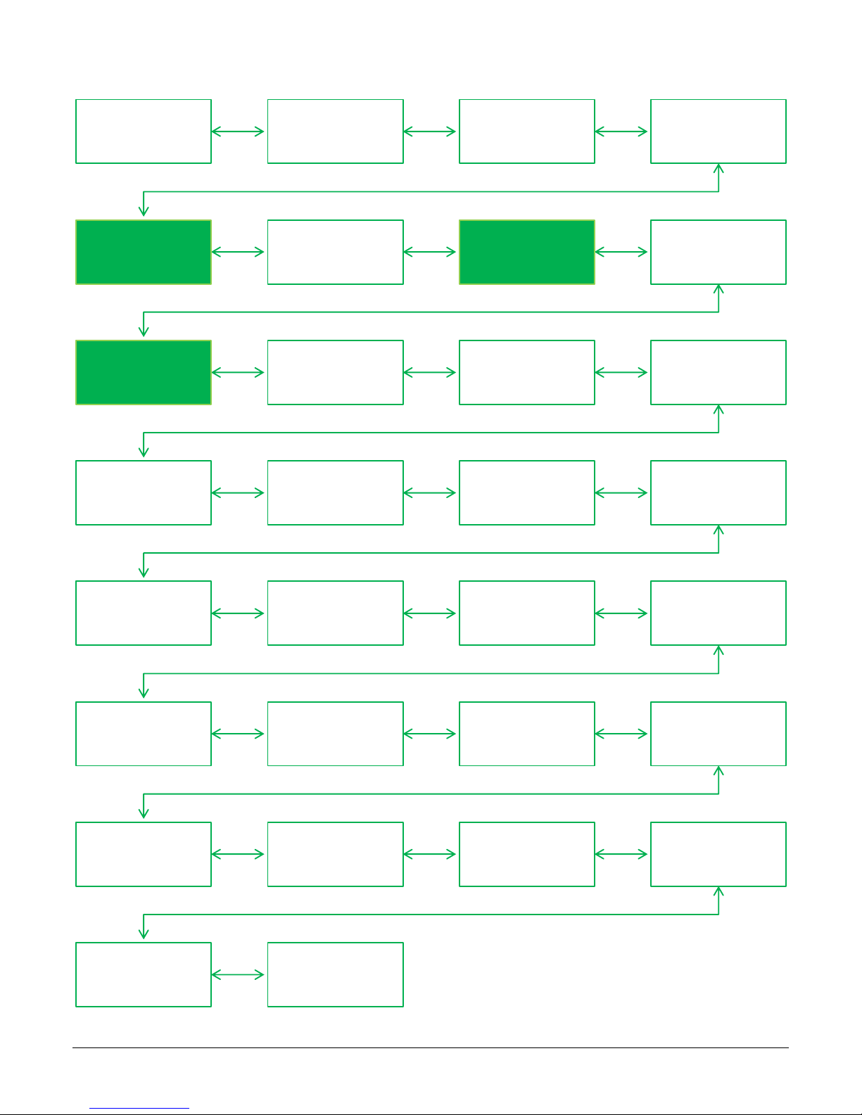
5.3. INSTALLER MENU
Language Date and Time AC fail (min) Remote Code
Learning:
Activators
TX Radio Code
Learning:
Bidirectional
Siren Test
Learning: Wireless
Zones
Zones Arming
Program
Alert Program Exit Time (sec)
Entry Time (sec)
PreAlarm Time
(sec)
External Alarm
Voice Messages
Program
Beep at Arming Wireless Blinding Door Control Supervision
Voice Calls
Number
Relay AUX1 Relay AUX2 Relay AUX3
Wireless
Saturation
Sensors Test GSM Test
GPRS Contact-ID
Test
Delete Telephone
Numbers
Reset
To go to next menu item press short the “#” button
To go to previous menu item press long the “#” button
Page 21
21
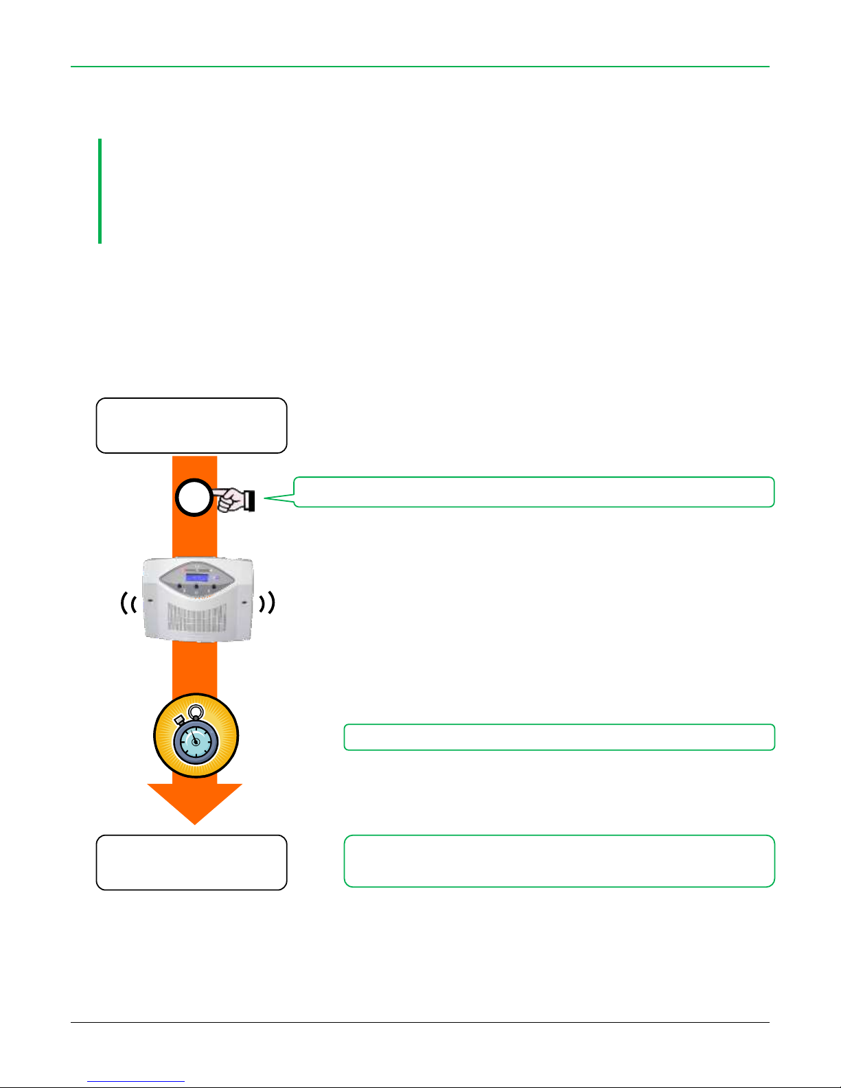
6. CLEAR THE CONTROL PANEL MEMORY
As in the first operation, it is highly recommended that you completely delete all the memory to reactivate default parameters and avoid
maintaining any of the test settings.
THIS FUNCTION DELETES THE MEMORY IN THE CONTROL PANEL, EXCEPT THE REGISTERD ALARM VOICE
MESSAGGES
AFTER THIS OPERATION THE CONTROL PANEL WILL BE COMPLETELY “EMPTY” MEANING ALL THE SENSORS,
REMOTE CONTROLS, KEYS AND PHONE NUMBERS WILL HAVE TO BE PROGRAMMED
CLEAR
enter in “INSTALLER MENU” (see paragraph 5)
go to “Reset” item
proceed as follows:
“ALERT” LED lights up
THE MEMORY IS CLEARED
WAIT SOME SECONDS
BEEP
BEEP
Press and hold the “X” button until some “beep”
X
Reset
Reset
Page 22
22
7. LEARN ACTIVATORS
This function is used to add new activators (remote and transponder keys) to the system.
The control panel has a maximum memory of up to 16 activators.
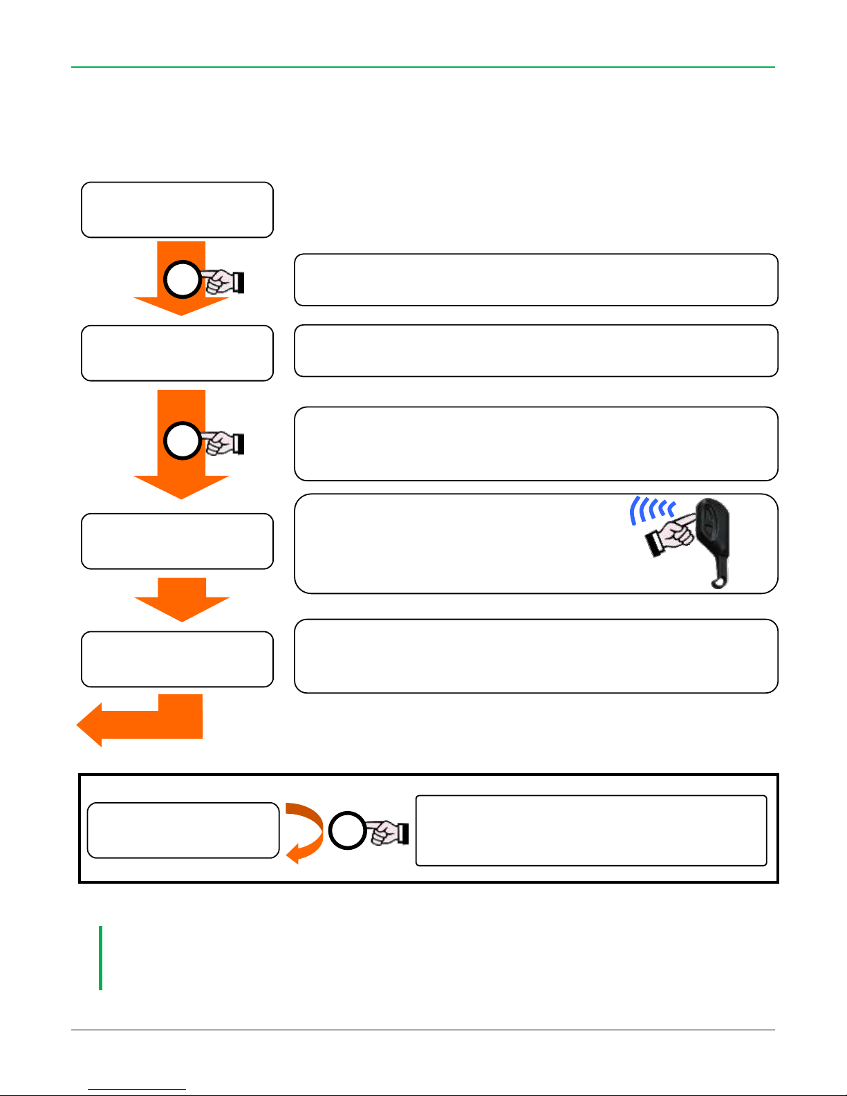
To add one or more activators you must enter the "Installer Menu” (see paragraph 5) and proceed as follows (do the same for each activator
to be learned):
IT IS NOT POSSIBLE TO LEARN THE SAME ACTIVATOR IN TWO DIFFERENT MEMORY POSITIONS.
It is possible to overwrite an already used memory space (losing the activator learnt before) just transmitting
the new activator code in the occupied memory space.
EXIT
Quick pressing on the “O” key will bring you to the next memory location (from “Activator
01” to “Activator 16”)
The “X” symbol indicates that the selected location has already stored an activator.
The “0” symbol indicates a vacant location.
Transmit only with
the activator to be memorized.
It can be a remote control,
a CHT/CHS key or a radio keyboard.
If the control panel receives the correct signal from the activator, it will confirm the
memorization with an "X" instead of "_ ".
If memorization is not possible, the control panel will emits three “beeps”.
After selecting the desired location, press the "X" key.
The display shows the symbol "_ ": the control panel is waiting for the radio code to add.
Select the the activator to delete then press and hold (at least 3
seconds) the "X" key.
When the "0" symbol appears the activator has been deleted.
Delete an activator
X
X
O
Learning O
Activator 01
Learning X
Activator 02
Learning _
Activator 02
Learning X
Activator 02
Learning X
Activator 02
Page 23
23
8. LEARN WIRELESS ZONES
There are two types of learning:
only by tamper code transmission
by detection (any radio code) transmission
The choice of the mode depends from the radio device to be learned: check which is the mode used by the device.
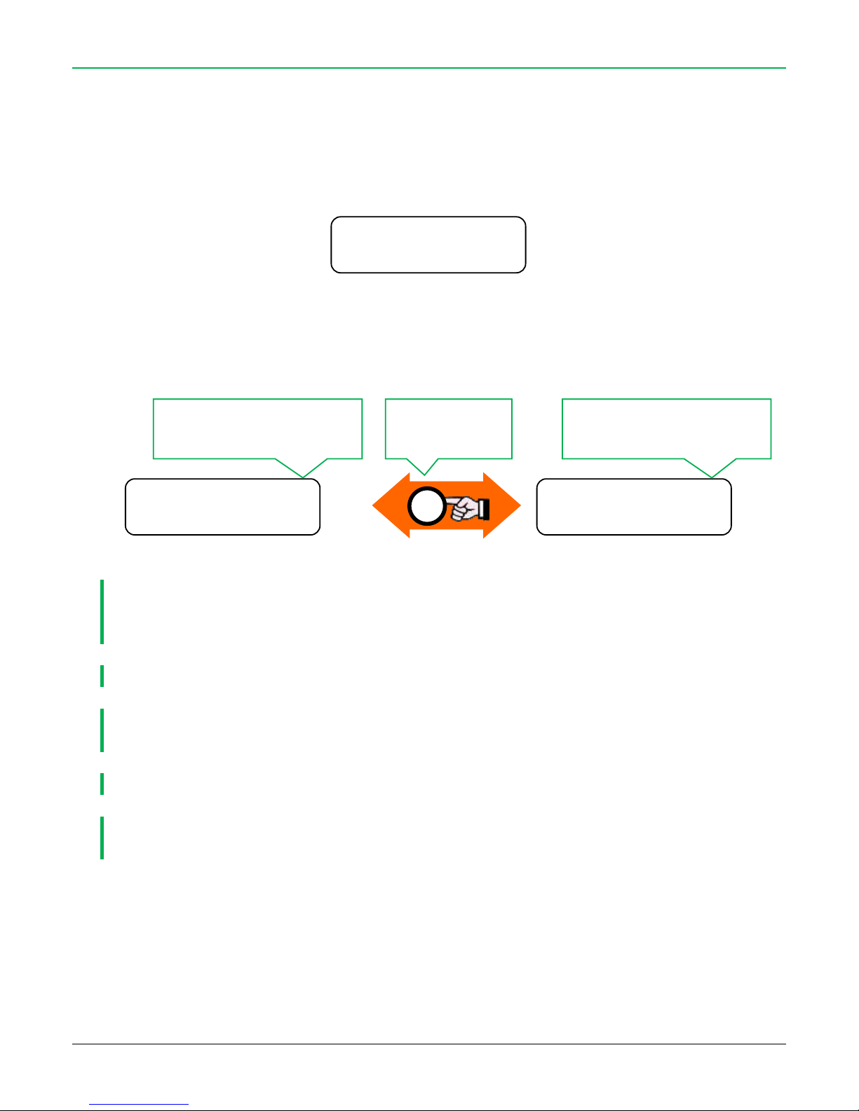
To add or modify radio device, enter in INSTALLER MENU and select “Radio Zone Learning”:
Select the learning mode: hold down the “#” button for at least 6 seconds until – after “Learning” – appears the “” symbol (for any radio
code) or disappears (by tamper):
“tamper” mode: this is the factory setting, the “” symbol is NOT present
“any radio code” mode: the “” symbol is present
THE CONTROL PANEL RECOGNIZES THE TYPE OF SENSOR LEARNED AND AUTOMATICALLY ALLOCATES IT TO THE
CORRESPONDING ZONE (EX.: CTSR AND DIRRVE TO PARTIAL; DIRRV TO TOTAL).
IT IS POSSIBLE TO MODIFY THIS ASSIGNMENT
IT IS NOT POSSIBLE TO ADD THE SAME SENSOR IN TWO DIFFERENT MEMORY LOCATIONS!
IT IS POSSIBLE TO OVERWRITE A MEMORY LOCATION THAT HAS ALREADY BEEN USED (DELETING THE SENSOR
THAT WAS ALREADY ALLOCATED), BY SIMPLY LEARN THE NEW SENSOR OVER THE ALREADY USED LOCATION.
INSTALLATION TIP: PERFORM ALL THE LEARNINGS AT BENCH, BEFORE INSTALLATION.
WHEN LEARNING A RADIO DEVICE, POWER OFF OR PREVENT DETECTIONS BY OTHER RADIO DEVICES: THE
CONTEMPORARY TRANSMISSION OF MORE THAN ONE RADIO CODE DOES NOT ALLOW CORRECT LEARNING.
Learning O
Radio Zone 01 P
Learning O
Radio Zone 01 P
Learning *O
Radio Zone 01 P
#
“” present: indicates the “detection/any
code” mode is used
“” not present: indicates the “tamper”
mode is used
Press for at least 6
seconds
Page 24
24
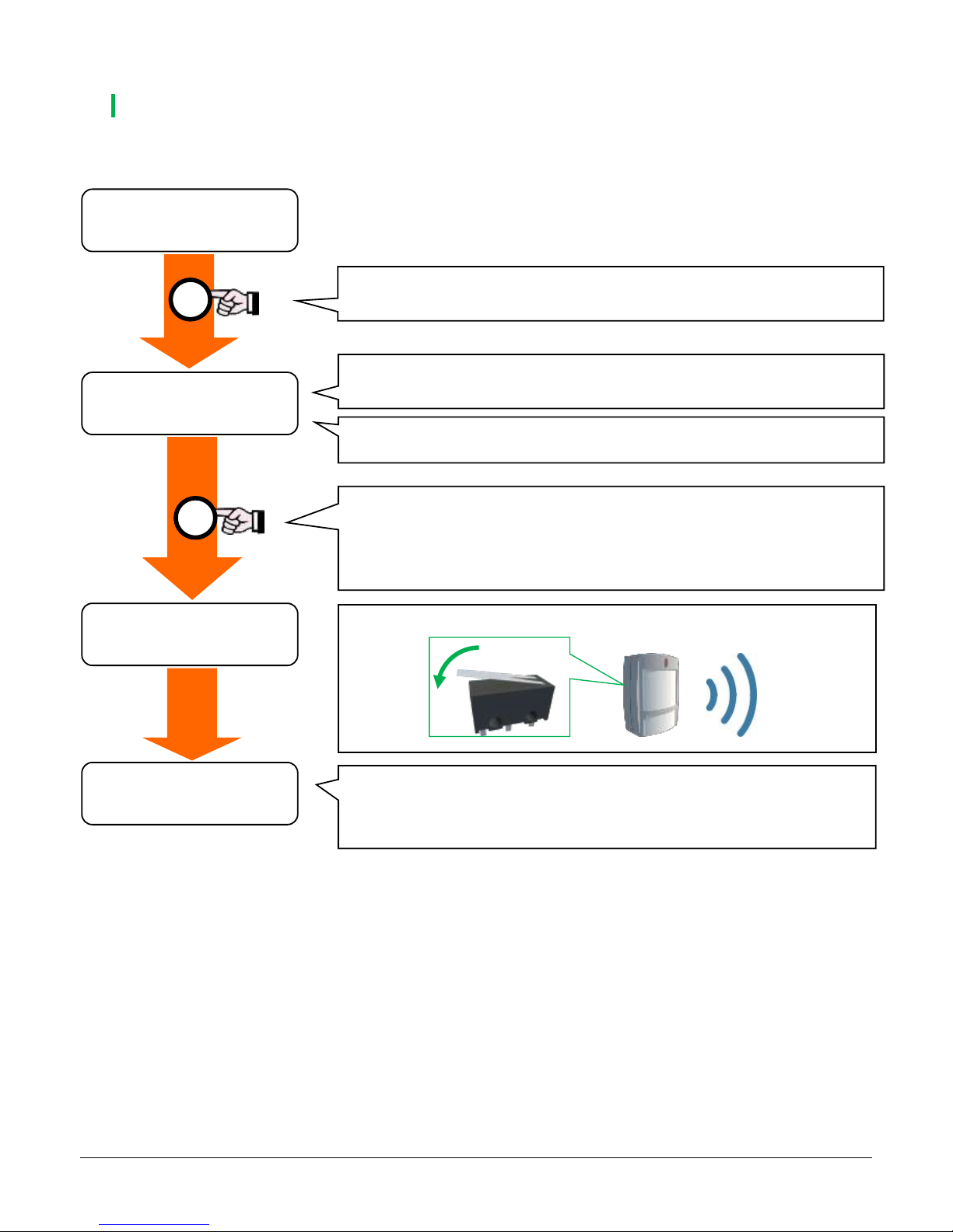
8.1. LEARN BY TAMPER CODE
THIS IS THE DEFAULT LEARNING MODE
To learn a device push its tamper switch:
Learning O
Radio Zone 01 P
Learning O
Radio Zone 02 P
Learning _
Radio Zone 02 P
Learning X
Radio Zone 02 P
Press the tamper switch on sensor
If the control panel receives a signal from the sensor correctly, it will confirm its memorization
with an “X” in the place of “_”
If the memory is not possible, the control panel will emit three “beeps”.
Once positioned in the desired zone:
Press “X” key quickly > The display shows “_”: the control panel is now ready for another
sensor code to be programmed
Hold down “X” key > Delete the current sensor
“X” = memory position already occupied by other device
“0” = memory position free
O
“P” = the device is perimeter type
“T” = the device is volumetric type (PIR)
X
At each quick press of the “O” key you go to the next memory location
(from “Radio Zone 01” to “Radio Zone 60”)
Page 25
25
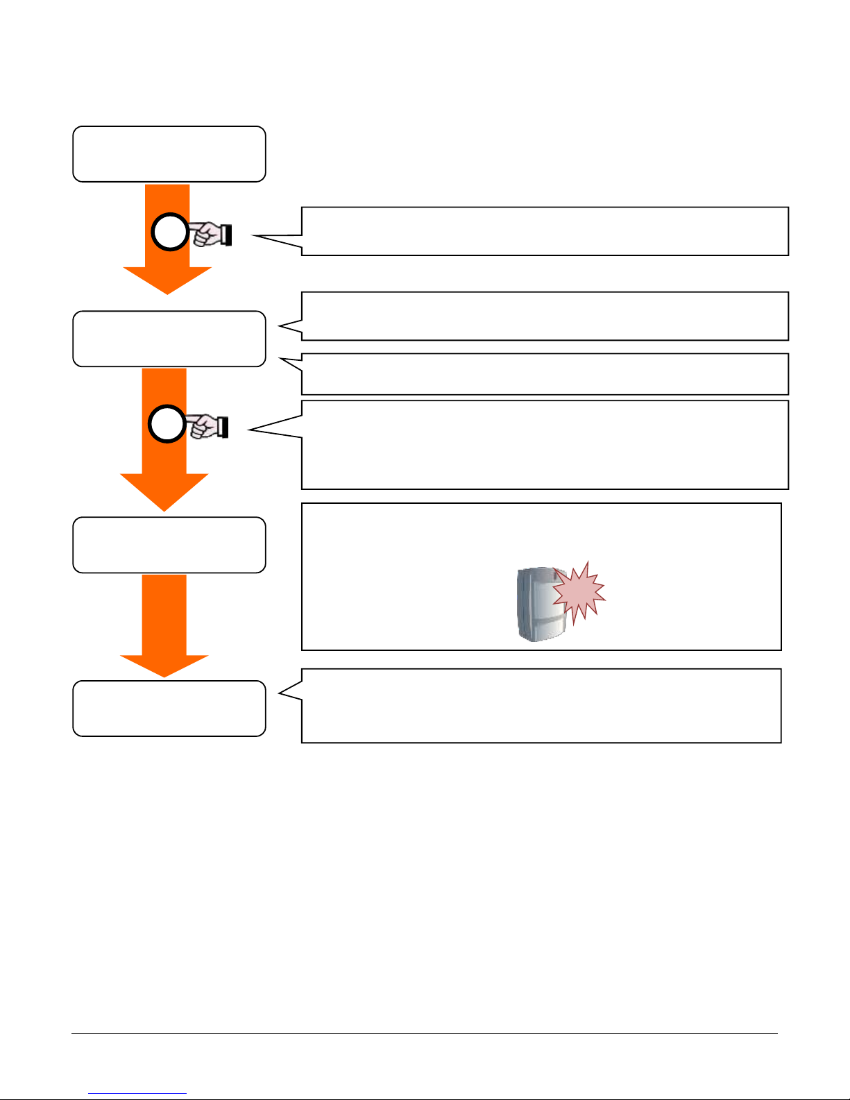
8.2. LEARN BY DETECTION CODE
This mode allow to learn the radio devices by any radio code they transmit.
It is possible learn the sensors just make a detection:
8.3. VOICE ALERT FROM WIRELESS ZONES 1 ÷ 30
The radio zones from 1 to 30 are associated to as many voice messages (Voice Alert).
These messages are played if:
the Alert function on control panel is enabled
the control panel is disarmed
one (or more) radio zone 1 ÷ 30 has Voice Alert enabled
the enabled radio zone detects
For how to custom the voice messages see “VOICE MESSAGES” paragraph in Installer menu
Learning *O
Radio Zone 01 P
Learning *O
Radio Zone 02 P
Learning *_
Radio Zone 02 P
Learning *X
Radio Zone 02 P
Make a detection only from the sensor to learn, so it sends its radio code to
the control panel:
If the control panel receives a signal from the sensor correctly, it will confirm its memorization
with an “X” in the place of “_”
If the memory is not possible, the control panel will emit three “beeps”.
Once positioned in the desired zone:
Press “X” key quickly > The display shows “_”: the control panel is now ready for another
sensor code to be programmed
Hold down “X” key > Delete the current sensor
“X” = memory position already occupied by other device
“0” = memory position free
O
“P” = the device is perimeter type
“T” = the device is volumetric type (PIR)
X
At each quick press of the “O” key you go to the next memory location
(from “Radio Zone 01” to “Radio Zone 60”)
Page 26
26
9. BI-DIRECTIONAL DEVICES
TO USE THIS FUNCTION IT IS MANDATORY TO ENABLE THE RADIO TRANSMISSION OF THE CONTROL PANEL (TX
RADIO CODE DIFFERENT THAN 000)
BI-DIRECTIONAL DEVICES COMPATIBLE WITH AUTO-LEARNING FUNCTION HERE DESCRIBED ARE ONLY THE ONES
EQUIPPED WITH FIRMWARE VERSION 4.30 OR ABOVE.
DEVICES WITH PREVIOUS VERSIONS OF FIRMWARE ARE NOT COMPATIBLE WITH THIS FUNCTION.
VERIFY THAT USED BI-DIRECTIONAL DEVICES ARE COMPATIBLE WITH AUTO-LEARNING FUNCTION, OTHERWISE
FOLLOW THE LEARNING PROCEDURE FOR NORMAL RADIO ZONES AND LEARNING THE CONTROL PANEL IN THE
DEVICE (AS DESCRIBED IN ITS MANUAL).
Devices supported by bi-directional learning are:
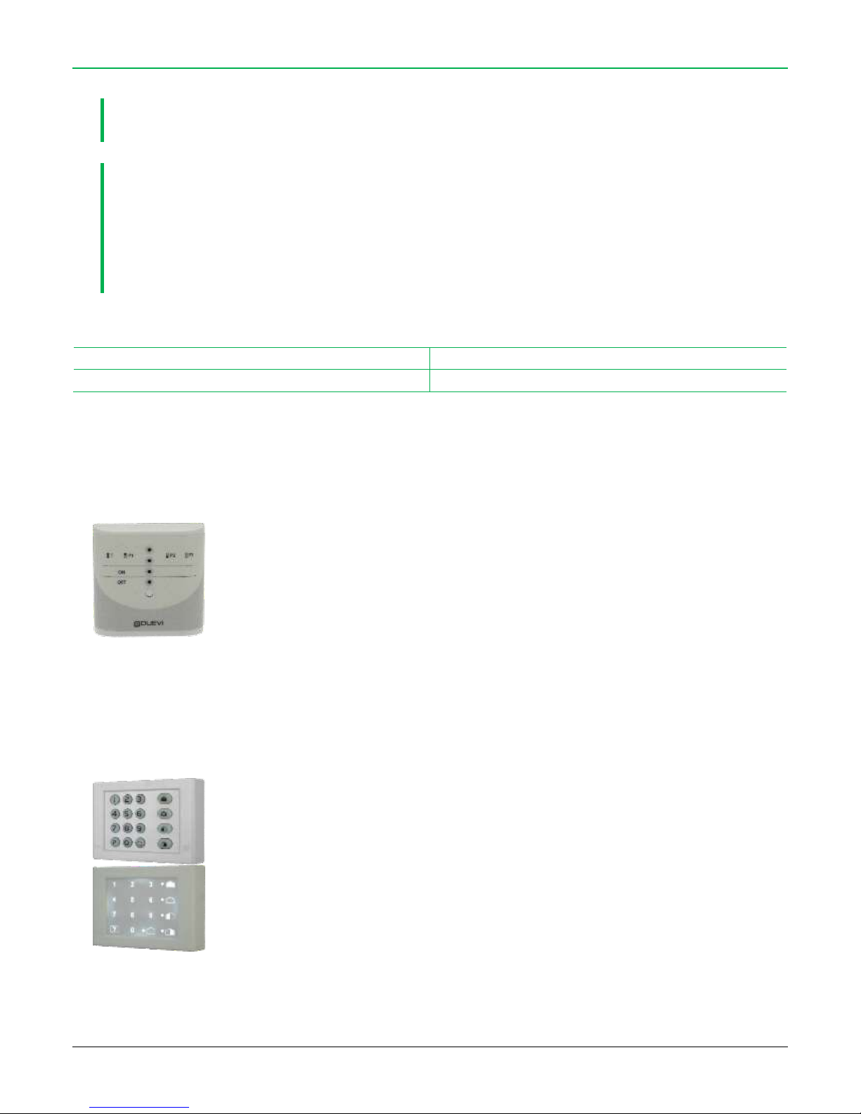
System status: STIMPIA-9
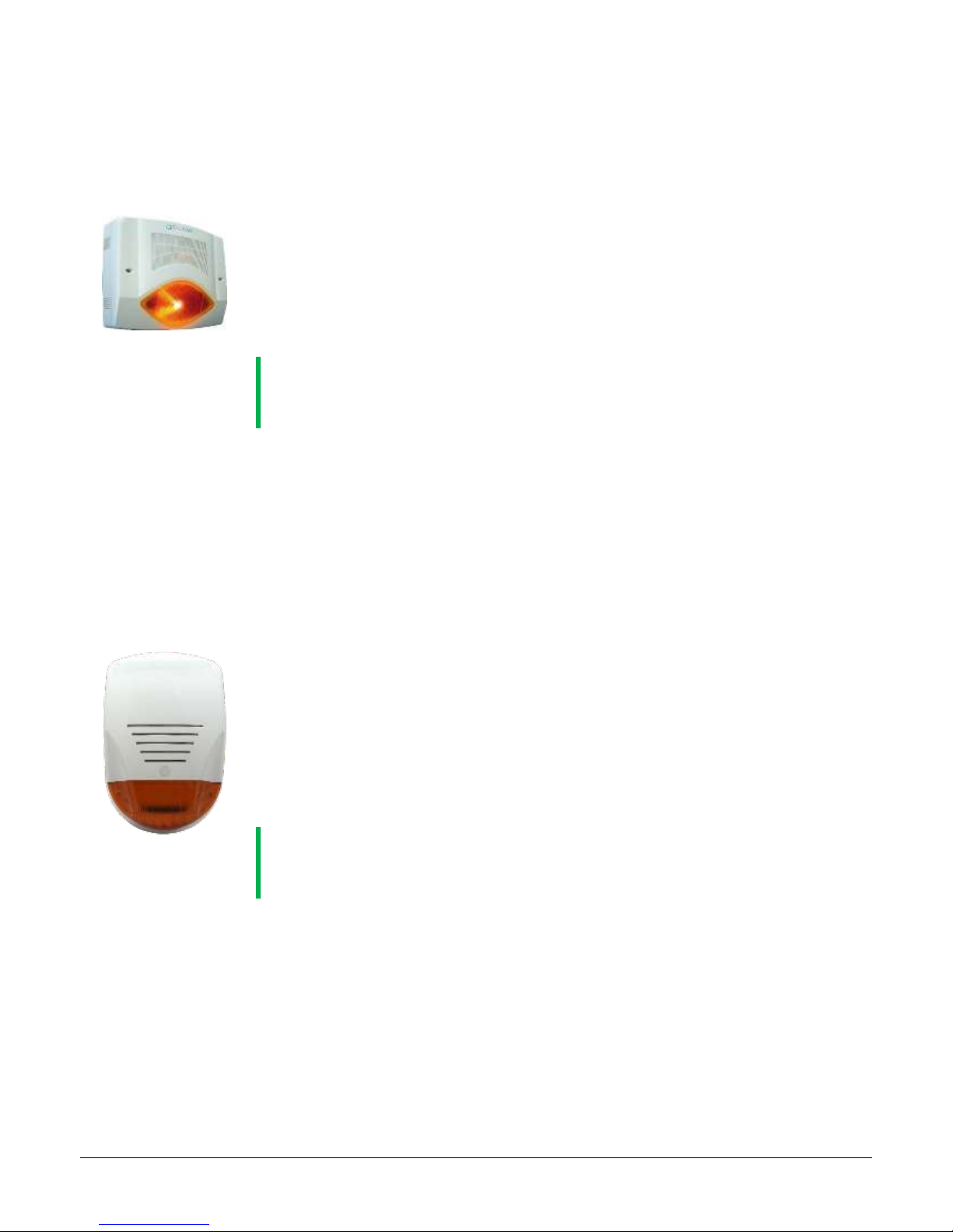
Radio sounder: SIRRA, SIRRB-NT, VV-ZELA-RB, VV-ZELA-RA
Radio keyboard: DVTR-RT, DVT-Touch, DVT-R-OLED
Electronic key radio reader: LET-PROX-W
9.1. ADD A RADIO SYSTEM STATUS VISUALIZER (STIMPIA-9)
1. Panel: enter in Installer Menu and select the “Bi-directional learning” item, select a free memory
position (marked with “O” symbol)
2. Viewer: open the jumper JP1 and power the viewer which emits a “beep” and starts to blink the RED
and GREEN LEDs
3. Panel: press within 30 seconds the “X” button. The control panel and the viewer will learn each other
their radio codes (the viewer lights solid on the RED and GREEN LEDs)
4. If all ends correctly: on control panel display appears “Learning OK”, the viewer emits 3 series of 2 “beep”
5. In case of errors repeat these steps
9.2. ADD A WIRELESS KEYBOARD (DVTR-RT, DVT-TOUCH)
1. Panel: enter in Installer Menu and select the “Bi-directional learning” item, select a free memory
position (marked with “O” symbol)
2. Keyboard: insert the batteries and wait the BLUE and GREEN LEDs start to blink contemporary
3. Panel: press within 30 seconds the “X” button
The control panel and the keyboard will learn each other their radio codes
4. If all ends correctly: on control panel display appears “Learning OK”, the keyboard emits 3 series of 2
“beep”
5. In case of errors repeat these steps
To learn the user codes follow the “learn activators” procedure
Page 27
27
9.3. ADD A WIRELESS SIREN (SIRRB-NT, SIRR-AC)
1. Panel: enter in Installer Menu and select the “Bi-directional learning” item, select a free memory
position (marked with “O” button)
2. Siren:
open jumper JP3 (PROGRAMMING) and JP5 (TAMPER) and power the sounder
close the jumper JP3: the sounder emits a long “beep” and lights on the flash
3. Panel: press within 30 seconds the “X” button
The control panel and the sounder will learn each other their radio codes
4. If all ends correctly: on control panel display appears “Learning OK”. The sounder emits some “beep”
and starts to blink each 1 second
5. Siren: open the jumper JP3: the sounder emits a “beep” and switch off the flash. Close the cover of the
sounder
NOTE: THE SOUNDER WILL BE ACTIVE ONLY AT THE EXIT FROM INSTALER MENU
THE SOUNDER CONFIRMS ITS ACTIVATION (EXITING FROM MENU) EMITTING A QUICK
“BEEP” SERIES AND LIGHTING ON THE FLASH FOR 2 SECONDS
6. In case of errors repeat these steps
9.4. ADD A WIRELESS SIREN (VV-ZELA-RA, VV-ZELA-RB)
1. Panel: enter in Installer Menu:
select the “TX Code” item and set a code different than “000” (zero-zero-zero)
select the “Bi-directional Learning” item, select an empty memory position (marked with “O”
symbol).
2. Siren: set DIP1 to ON: the siren emits a long “BEEP” and lights on the lamp
3. Panel: press - within 30 seconds – the button to start the learning (“X” or “”).
The panel and the siren will learn each other radio codes (this operation is automatic).
4. If all ends correctly: on control panel display appears “Learning OK”. The siren emits some “BEEP”, its
LED lamp flashes and then stay solid on.
5. Siren: set DIP1 to OFF: the siren emits a “BEEP” and switches off the lamp. Close the cover of the
sounder.
NOTE: THE SOUNDER WILL BE ACTIVE ONLY AT THE EXIT FROM INSTALER MENU
THE SOUNDER CONFIRMS ITS ACTIVATION (EXITING FROM MENU) EMITTING A QUICK
“BEEP” SERIES AND LIGHTING ON THE FLASH FOR 2 SECONDS
6. In case of errors repeat these steps
Page 28
28
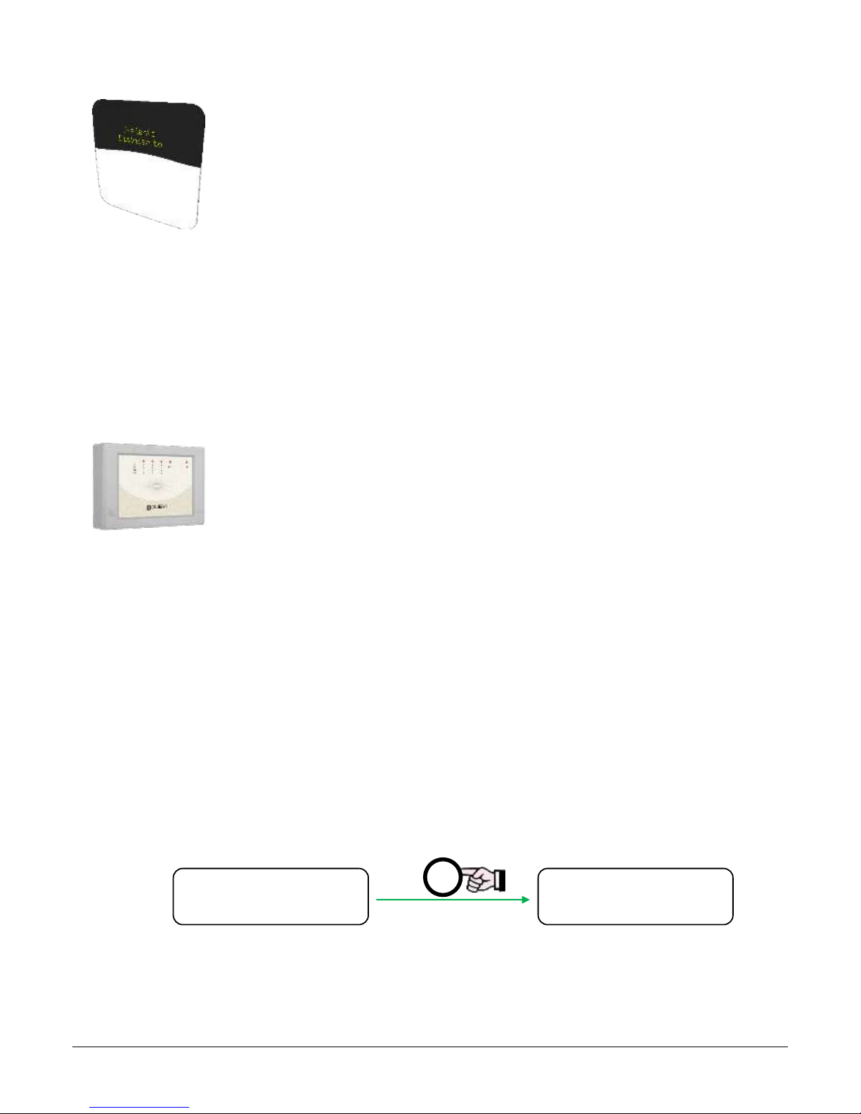
9.5. ADD A WIRELESS KEYBOARD WITH DISPLAY (DVT-R-OLED)
1. Panel: enter in Installer Menu and select “Bi-directional Learning” item, select a free memory position
(marked with “O” symbol) and press “X” button
2. Keyboard: enter in Installer Menu, select “Bi-directional” and press "" to start the pairing
The keyboard and the panel will learn each other radio codes.
3. If all ends correctly: on control panel display appears “Learning OK”
4. In case of errors repeat these steps
To learn the user codes follow the “learn activators” procedure
9.6. ADD A RADIO TRANSPONDER READER (LET-PROX-W)
1. Panel: enter in Installer Menu and select the “Bi-directional learning” item, select a free memory
position (marked with “O” symbol)
2. Reader:
set DIP1 to ON
all LEDs start to blink
pass the electronic key over the reader: the reader emits a long “beep”
Note: in this phase the key is used only for the combining of the reader with the control panel, it is not stored
in the reader
set DIP1 to OFF, the GREEN and BLUE LEDs start to blink
3. Panel: press within 30 seconds the “X” button
The control panel and the reader will learn each other their radio codes
4. If all ends correctly: on control panel display appears “Learning OK”, the reader emits 3 serie of 2 “beep”
5. In case of errors repeat these steps
To learn the keys follow the “learn activators” procedure
9.7. DELETE A BI-DIRECTIONAL DEVICE
1. Enter in Installer Menu and select the “Bi-directional learning” item
2. Select the device to delete with the “O” button
3. Hold down the “X” button until a “beep” (at least 5 seconds)
4. On display the “X” is changed to “0”, indicating that the device is deleted
Learn Bi-dir. X
Perip. 02
Learn Bi-dir. O
Perip. 02
X
Page 29
29
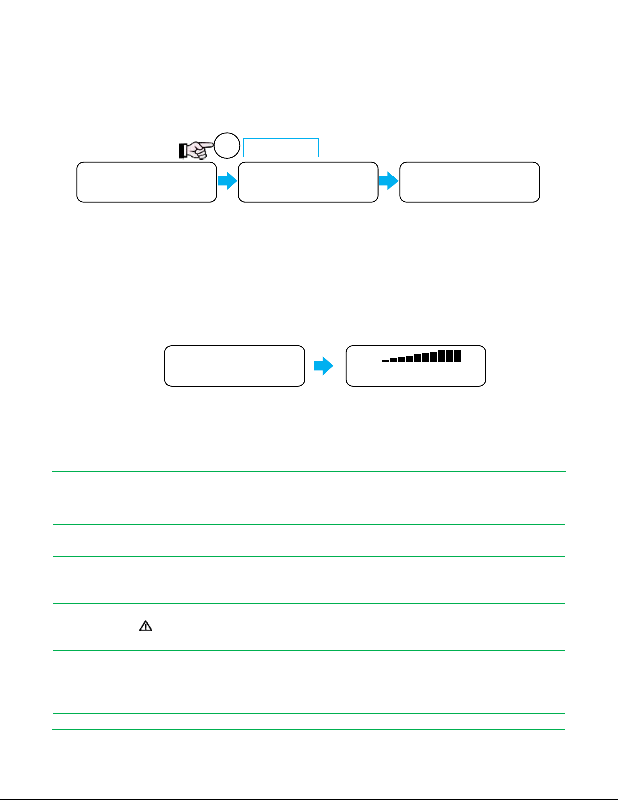
10. PANEL TEST
To enter in “Panel Test”:
1. Disarm the panel (even if already disarmed)
2. Hold down the “#” button until the display shows “Panel Test”
This test allows to verify if the activators and zones work correctly with the panel.
Each time the panel receives a signal from a device/zone, it shows on display the device/zone name and emits a “beep”.
To exit from “Panel Test” hold down the “#” button or wait until the panel exit (about 2 minutes).
10.1. “RADIO LEVEL” TOOL
Inside the “Panel Test” is possible to enable the “Radio level” tool to visualize the radio signal quantity received by control panel from any
radio device. This tool allows to understand if the signal level that reaches the panel is strong or weak.
To activate the tool, press the “X” button.
11. PROGRAM THE RELAY OUTPUTS (AUX1, AUX2, AUX3)
The relay outputs AUX1, AUX2 and AUX3 can be combined to control panel events: the output will switch when the combined event occurs.
Event
Description
ON/OFF
The AUX output is activated/deactivated by SMS command
The SMS commands are *: xxxx#out onttt, xxxx#out on, xxxx#out off
TEMPERATURE
This function can be used only in presence of the temperature probe (optional): the control panel uses the AUX
output to drive the heating system, according to the measured and wanted temperature.
The SMS commands are *: xxxx#temp onTT, xxxx#temp off
RING
The AUX output switches for 2 seconds when the control panel receives a phone call from known telephone number.
When the AUX relay is set as RING, the call to control panel is used to switch the output
and therefore the VOICE MENU is DISABLED!
GSM JAM
In case the GSM modem detects a GSM jamming, the AUX output switches. Useful to connect alternative signalling
systems (ex.: PSTN, radio bridges, …).
GSM FAILURE
The AUX output switches in case of: no GSM signal, SIM failure or missing connection to the network. The output
switches after about 10 minutes. The output backs to rest after 10 seconds from the end of problem.
SILENT ALARM
The AUX output is activated in case of Silent Alarm events.
12:30 06/02/12 ▄
Disarmed ▄ X
Panel Test
Radio Zone 02 P
12:30 06/02/16 ▄
Disarmed ▄ X
Panel Test
Rx=
Press long
#
Page 30
30
TC
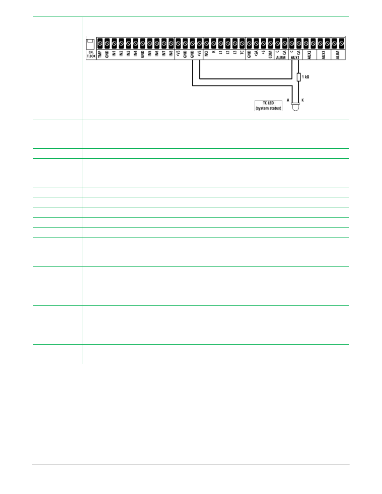
The AUX output is activated when the control panel is armed (totally or partially), it backs to rest when the panel is
disarmed (its status change immediately without Exit Time).
Connection example: signalling TC status with LED
TECHNOLOGIC
At each detection of a technologic sensor (active 24h/24, regardless the panel is armed or not), the AUX output
changes status. It is possible to connect – for example – an additional signalling system or an actuator.
PRE-ALARM
When the pre-alarm event starts, the AUX output switches (for the lasting of the Pre-alarm time).
ALERT
The AUX output switches at each Alert signalling.
TEMPO
INGRESSO
The AUX output stays active for the whole Entry Time
TEMPO USCITA
The AUX output stays active for the whole Exit Time
INS. TOTALE
The AUX output is activated at system armed in TOTAL mode. The output backs to rest when system is disarmed.
INS. PARZIALE
The AUX output is activated at system armed in PARTIAL mode. The output backs to rest when system is disarmed.
INS. ESTERNO
The AUX output is activated at system armed in OUTDOOR mode. The output backs to rest when system is disarmed.
TAMPER
The AUX output is activated in case of TAMPER alarm
PANICO
The AUX output is activated in case of PANIC event
ASSENZA RETE
The AUX output stays active during the “AC power fail” signalling
BATTERIA
BASSA
The AUX output is activated when the control panel battery drops below the minimum level.
ACCECAMENTO
RADIO
The AUX output is activated in case of radio frequency tamèering attempts
SEGNALAZIONE
PORTE APERTE
The AUX output os activated during the “opened door” signalling (at arming, if the panel found “opened doors”, it
alerts the user).
PORTE APERTE
The AUX output is activated when – at system disarmed – one or more zones are opened.
This signalling is the same information given by the YELLOW LED L2.
SUONERIA
ESTERNI
The AUX output is activated in case of detection of external zones, when “External zone ring” is on.
TELECOMANDO
16
The activator learned in memory poition n. 16, when used, activates the AUX output.
The activator can not be used for arm/disarm the control panel.
* For details about the SMS commands see USER MANUAL
The relay outputs programming can be done via Installer Menu or software.
It is necessary to connect an additional relay board to the AUX relais in case the load exceed the maximum limits of outputs.
Page 31
31
12. FUNCTIONS (INSTALLER MENU)
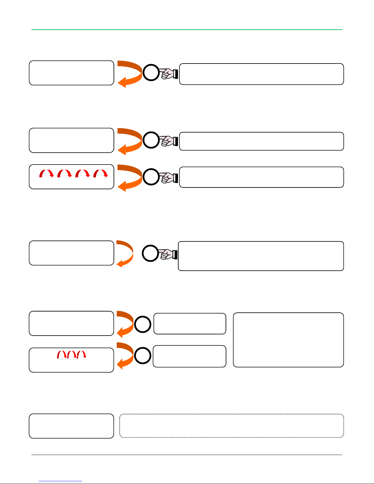
12.1. LANGUAGE
12.2. DATE AND TIME
12.3. POWER FAIL TIME
Time in minutes before the control panel signal “AC fail” in case of power loss.
12.4. DIALLER CODE
12.5. LEARN ACTIVATORS
3 4 6 7
10:20 01/02/12
Increase the value of
one unit
Select the next digit
This is the 4 digit security code for
access to dialler function: it is
required for SMS commands and
Voice Menu.
Factory value: “0000” (four zeros)
Activators Learning
See paragraph “ACTIVATOR LEARNING”
Each pressure select: HOURS, MINUTES, DAY, MONTH,
YEAR
Each pressure increase the value of one unit
Minutes for Power fail
Press 1 time to start counting from zero.
Press again to stop the counting at desired value.
X
X
O
O
X
Date and Time
10:20 01/02/12
AC fail (min)
10
Remote Code
0000
Learning O
Activator 01
Each pressure change the language of the control panel:
ITALIANO, ENGLISH, FRANCAIS, ESPANOL
X
Language
Italiano
Page 32
32
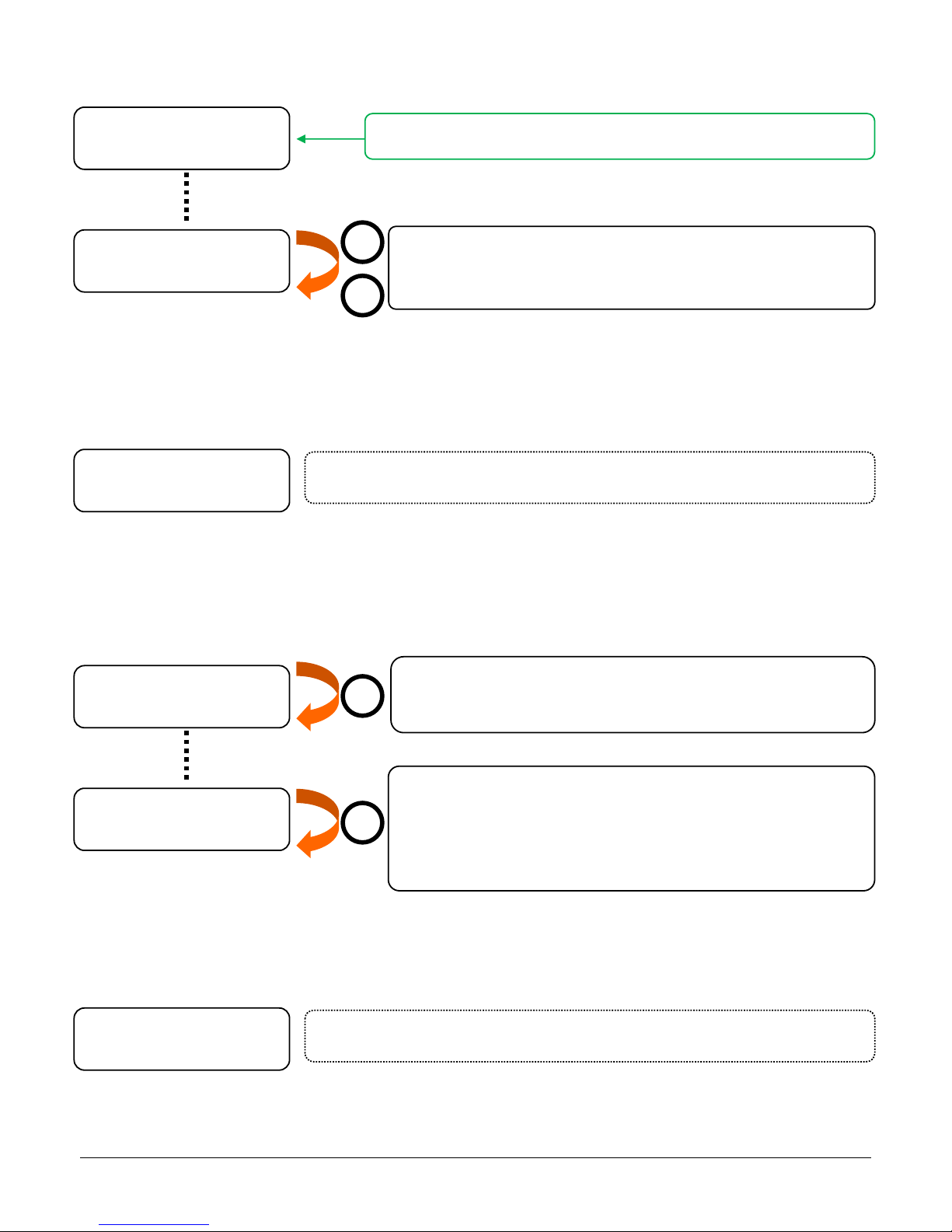
12.6. TX RADIO CODE
Enable and disable the control panel radio transmission.
12.7. LEARN BI-DIRECTIONAL DEVICES
12.8. WIRELESS SIREN TEST
To check the quality of radio communication between the control panel and radio sounder.
12.9. LEARN WIRELESS ZONES
Learning Sensors
See “LEARNING WIRELESS ZONES” section
An alarm is stimulated: the alarm radio code is sent to the siren
and then after 3 seconds the disarm radio code. If the
communication is correct the siren will sound for 3 seconds
The siren is required to send its tamper code. The siren responds
with a blinking light and sends the code requested.
If the code has already been learned the control panel emits a few
“beeps” (confirmation of learning).
If the code was not saved it will not “beep”
X
O
TX Radio Code
201
Learning Bi-Directional devices
See paragraph “BI-DIRECTIONAL LEARNING”
Learning X
Bi-Direct. 01
Siren Test
Siren Test
Learning X
Radio Zone 01 P
IF THE CODE IS “000” THE RADIO TRANSMISSION IS OFF
To enable the radio transmission, insert a value different than “000”:
Use the “O” button to change the value of the digit
Use the “X” button to move to next
O
TX Radio Code
000
X
Page 33
33
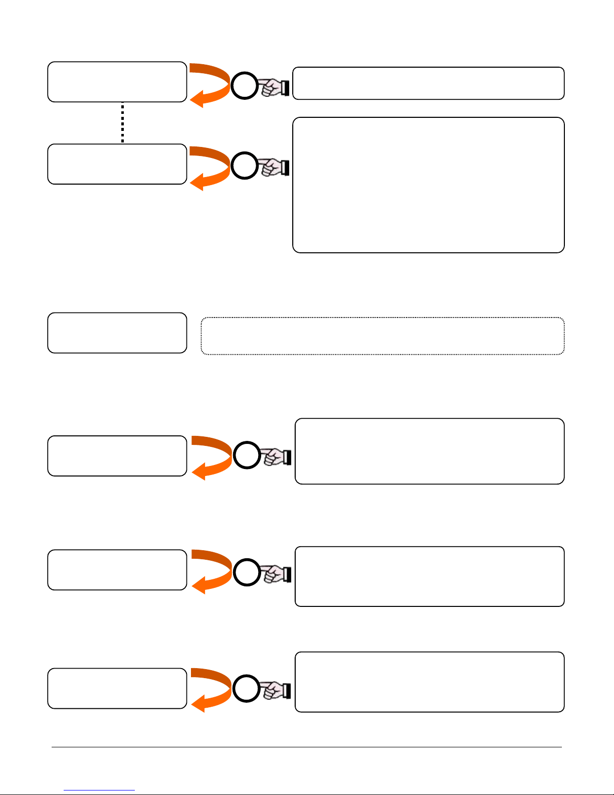
12.10. ARMING PROGRAMS
Programming the type of insertion and activation of each zone:
12.11. ALERT
12.12. EXIT TIME
12.13. ENTRY TIME
12.14. PRE-ALARM TIME
At each press, it will move to the next zone (Wired Zones
and Radio Zones)
Short press changes the status:
R = sensor with Entry Time
I = Instantaneous alarm sensor
D = sensor Disabled
Long press changes insertion:
T = Total
P = Partial
E = External
Time for exit in seconds
Press 1 time to start count from zero
Press again to stop the count at the desired value
Time for entry in seconds
Press 1 time to start count from zero
Press again to stop the count at the desired value
Time of PreAlarm in seconds
Press 1 time to start count from zero
Press again to stop the count at the desired value
Programming ALERT warning sound
(See USER MANUAL)
X
X
X
X
O
Zone Arm.Progr R
Wired Zone 01 P
Zone Arm.Progr I
Radio Zone 01 P
Alert Progr. D
Wired Zone 01 P
Exit Time (sec)
10
Entry Time (sec)
10
PreAlarm Time(s)
00
Page 34
34
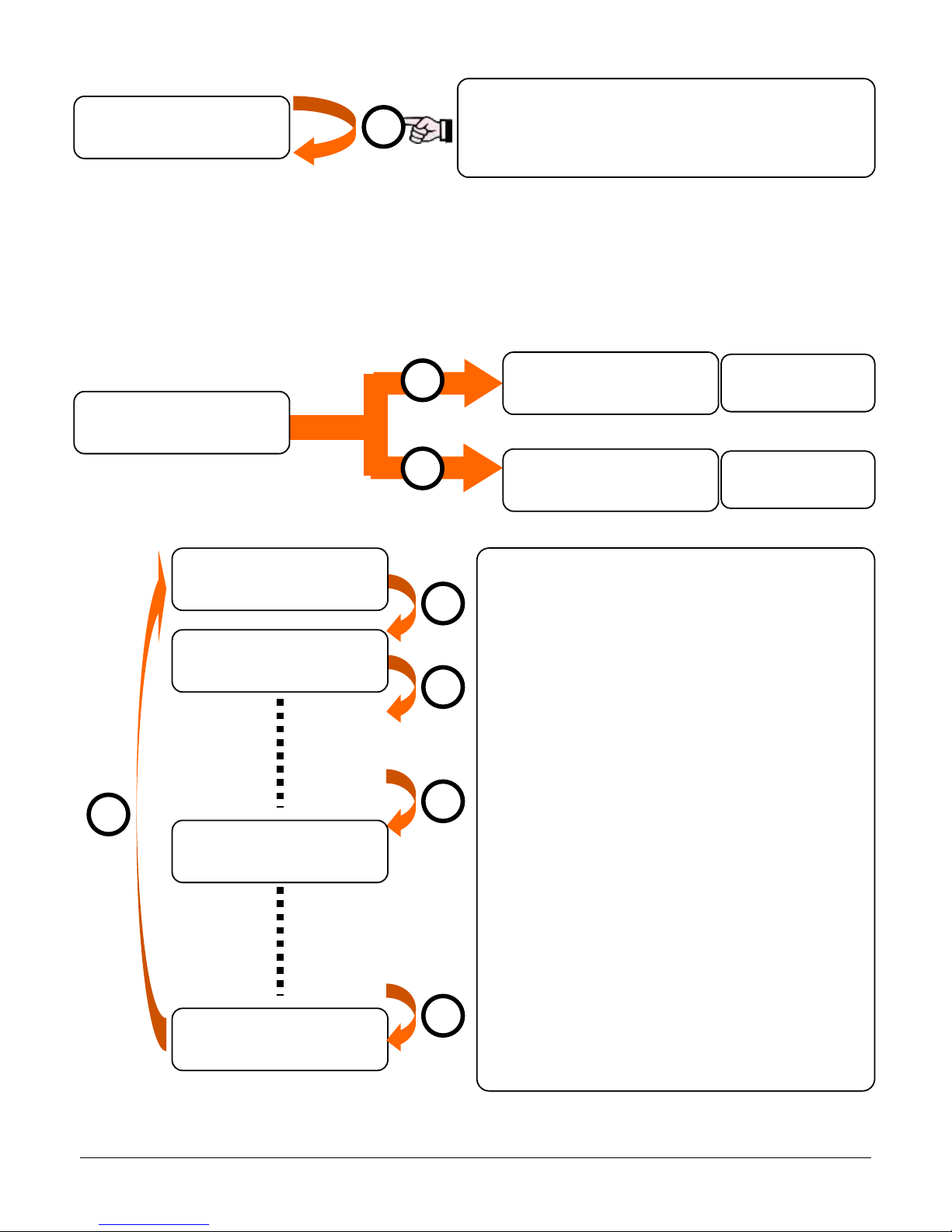
12.15. EXTERNAL/OUTDOOR ALERT
12.16. VOICE MESSAGES
Allows the recording and listening of vocal messages used by the GSM dialler in the case of: alarm, panic, silent alarm (see USER MANUAL
for details).
Programmazione Messaggi Vocali
Select the voice message to listen or edit with the
“O” button.
Press and release the “X” button to play the
message.
Press long the “X” button to record a new message
(max 12 seconds); it is possible to stop the recording
pressing the “#” button.
Messages list:
Alarm
Silent Alarm
Panic
Disarmed with coercion
Disarmed
Total armed
Partial armed
External armed
Tech message 01
…
Tech message 11
Message Radio Sensor 01 (Voice alert)
…
Message Radio Sensor 30 (Voice alert)
< 2 sec.
> 2 sec.
External Zones Alarm (Yes/No)
Press “X” to activate or deactivate this function
(see USER MANUAL)
X X O O O
Listen the message
Record the
message
X
O
External Alarm
No
Voice Msg Progr.
Alarm Message
Voice Msg Progr.
Alarm Message
Voice Msg Progr.
Panic
Voice Msg Progr.
Tech Message 11
Voice Msg Progr.
Record Message
Voice Msg Progr.
Play Message
Voice Msg Progr.
Message Zone 30
O
Page 35
35
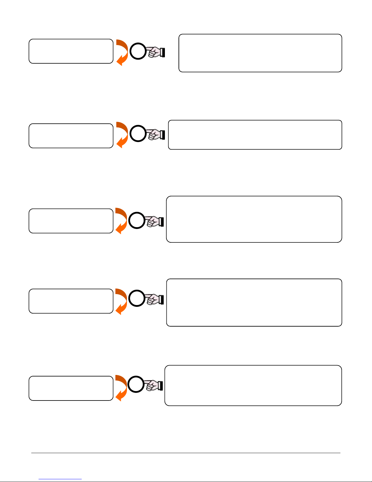
12.17. ARM/DISARM BEEP
12.18. RADIO BLINDING
Set the radio jamming protection level.
12.19. DOOR CONTROL
12.20. SUPERVISION
12.21. VOICE CALL NUMBER
The dialler – in case of alarm – sends all SMS to the telephone numbers (according with settings).
Once finished with the SMS, it starts with calls – for the number of times set – to the telephone numbers enabled: it starts from the first,
calling it as many times as set, then move on the next one and so on.
Number of Vocal Calls (1 ÷ 9)
Set the number of calls that the control panel will make to
each phone number stored, in the case of alarm
Each time you press "X" you increase the value
Radio Jamming (level 0, … level 4)
The level “0” indicates no-jamming protection (OFF).
See the dedicated paragraph (18)
Door Control (Yes/No)
The control panel runs a check on all the zones to verify if
there are any “opened doors” at the moment it is armed
and signals an abnormal situation
The signal lasts about 10 seconds
Sensors Supervision (Yes/No)
The control panel checks all the memorized sensors every
hour to make sure they are still operating. If a sensor does
not respond for three consecutive times within 12h, the
panel indicates "Supervision Failed”
X
X
X
X
“Beep” for arming/disarming
Press the “X” to activate (ON) o deactivate (OFF) the
acoustic signal at the arming or disarming
X
Beep Arm/Disarm
ON
W.less Blinding
0
Door Control
YES
Supervision
No
Voice Call Numb.
1
Page 36
36
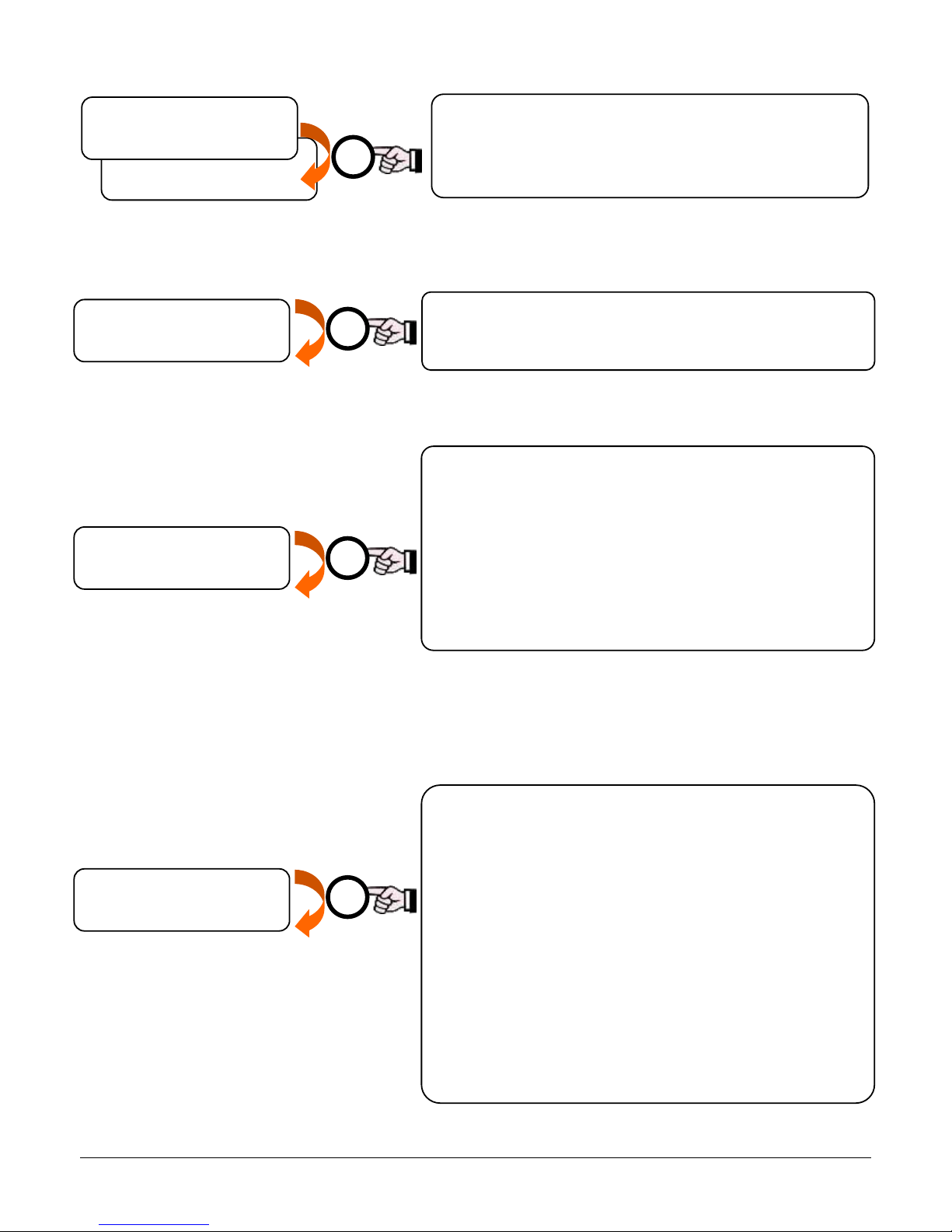
12.22. RELAY AUX (AUX1, AUX2, AUX3)
12.23. RADIO SATURATION
12.24. RADIO ZONE TEST
12.25. GSM TEST
Before activate the GSM test it is required to program the first telephone number on control panel (by software or SMS, see Software and
User manuals). If not, the GSM test fails. The telephone number must be a mobile type (to perform correct calls and SMS sending tests).
Relay Aux 1
JAM
Briefly press the "X" will activate the test mode of the
wireless sensors learned.
The panel shows the number of sensors currently
memorized and their names.
When a sensor detects, the control panel beeps and displays
the name of the violated zone, then decreases the number
of remaining sensors left to test.
The test has success when the display indicates: "Number of
sensors 00"
Radio Saturation Test
Press the "X" key to activate/deactivate the Radio Saturation
Test (see paragraph 17).
X
X
Quickly press the “X” button to activate the test mode.
Press the “#” button to go on the test:
Modem working test (Modem OK / NOT OK)
Network Operator (operator name)
Modem signal (graphic bar for GSM field)
Ask for residual credit (change YES/NO with “O” button)
o YES: credit request, visualized on display
o NO: next step
GSM test (change YES/NO with “X” button):
o YES: GSM network communication test (SMS
then VOCAL CALL to the first memory number)
Stop the test with the “X” button
o NO: end GSM test
X
Radio Saturation
YES
Relay Aux 1
ON/OFF
Sensors Test
GSM Test
X
Programmable relais AUX outputs (AUX1, AUX2, AUX3)
Set the event which cause the output switching.
Press “X” button to change the event.
(see the paragraph 11)
Page 37
37
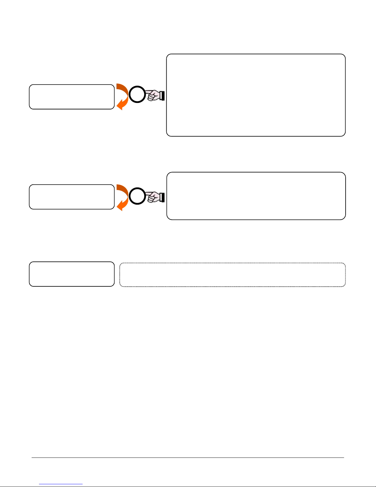
12.26. GPRS CONTACT ID TEST
Before activate the GPRS Contact ID test it is required to program the Contact ID parameters (see Software manual). If not, the GPRS test fails:
press “X” button to stop and exit the test.
12.27. DELETE TELEPHONE NUMBERS
12.28. RESET
Reset
See paragraph 6, “CLEAR THE CONTROL PANEL MEMORY”
Quickly press the “X” button to activate the test mode.
Press the “#” button to go on the test:
Modem working test (Modem OK / NOT OK)
Network Operator (operator name)
Modem signal (graphic bar for GSM field)
GPRS test (change YES/NO with “X” button)
o YES: GPRS communication test
o NO: stop GPRS test
X
GPRS/C.ID Test
RESET
Delete Telephone Numbers
Press and hold the “X” button to clear the whole telephone
number list and re-set to factory settings.
At the end of process, the control panel emits five “beeps”
and the Alert LED blinks.
X
Delete Tel.Numb.
Page 38
38
13. PROGRAM THE GSM COMMUNICATOR
13.1. PROGRAM TELEPHONE NUMBERS
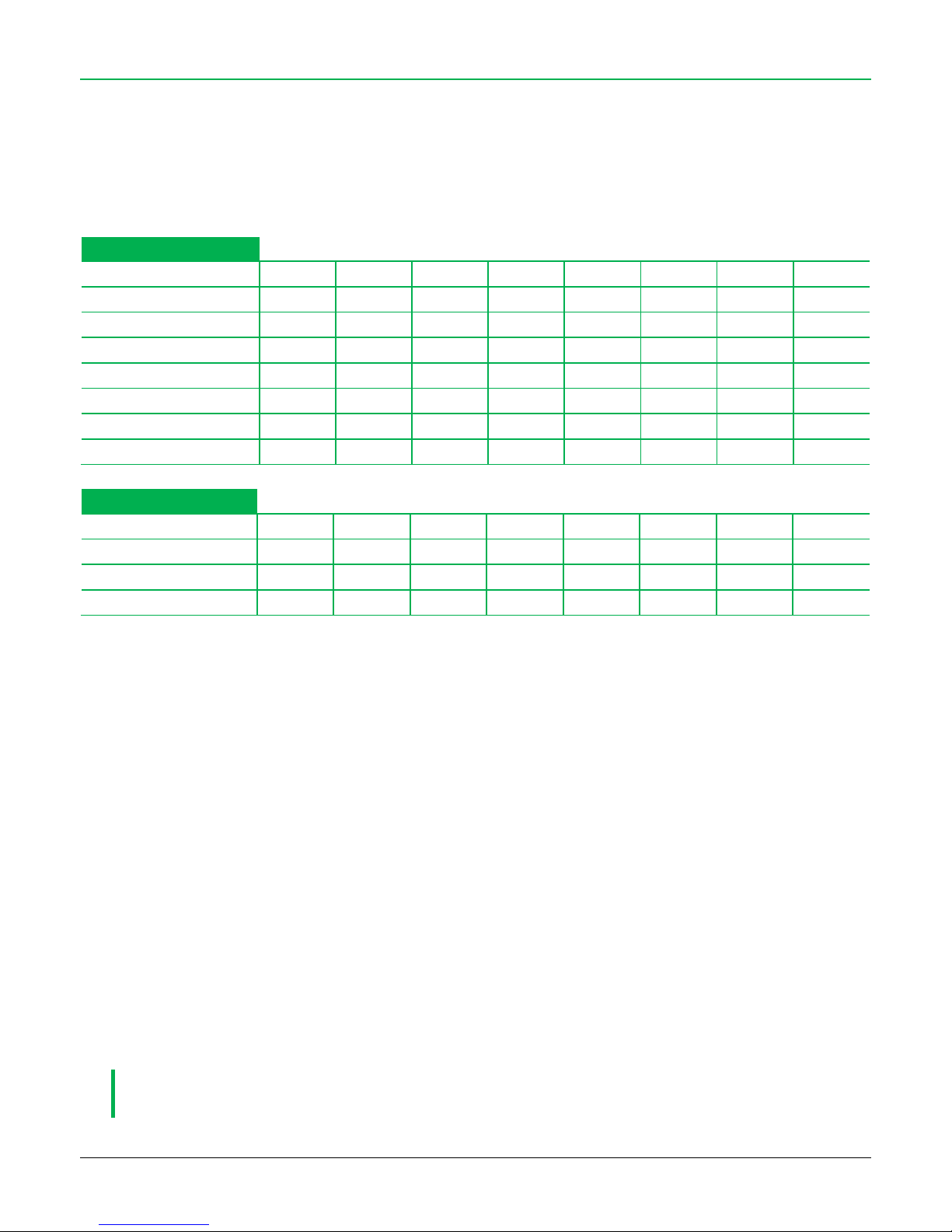
The control panel can memorize up to 8 telephone numbers to send alerts via SMS and/or voice calls.
All the memory positions have different settings by factory.
Store the telephone numbers in memory position according to the type of alerts each number must receive.
SMS
Tel. 1
Tel. 2
Tel. 3
Tel. 4
Tel. 5
Tel. 6
Tel. 7
Tel. 8
Arming status
●
Alarm
● ● ●
●
Panic
● ● ●
●
Silent Alarm
● ● ●
●
Supervision
● ● ●
●
Power status
● ● ●
●
Battery status
● ● ●
●
VOICE CALL
Tel. 1
Tel. 2
Tel. 3
Tel. 4
Tel. 5
Tel. 6
Tel. 7
Tel. 8
Alarm
● ● ● ● ● ● ●
●
Panic
● ● ●
●
Silent Alarm
● ● ●
●
Memory position 1 ÷ 4 are enabled to receive voice calls and SMS for alerts and technical notifications. Program in these positions ONLY
MOBILE NUMBERS.
Memory positions 5 ÷ 8 are enabled only to voice calls for alarm, and can be used for landline, mobile and emergency numbers.
SMS
Arming Status: for each arming / disarming event, an SMS is sent with information on the new state of activation of the alarm system.
Alarm: signal for alarm in progress.
Panic: notice of activation from special EMERGENCY remote control.
Silent Alarm: notice of activation from special EMERGENCY remote control.
Supervision: information for proper functioning of (monthly) internal GSM modem.
Power supply Status:
o Power line: Notice of failure / power supply recovery from power line.
o Battery status: low battery status indicator.
VOICE CALLS
Voice calls: warning alarm function, panic or tele-alarm via vocal calls
DURING THE ALARM VOICE CALL, TO STOP THE ONGOING CALL JUST DIGIT THE CODE “0#” (ZERO + #) ON THE
PHONE KEYBOARD.
Page 39

39
DURING THE ALARM VOICE CALL, TO STOP THE ONGOING CALLS AND SMS MESSAGES JUST DIGIT THE CODE
“xxxx#” (REMOTE CODE + #) ON THE PHONE KEYBOARD. THE CONTROL PANEL STAYS ARMED. THE PANIC AND
SILEN ALARM EVENTS ARE NOT STOPPED.
DURING THE ALARM VOICE CALL, TO STOP THE ONGOING CALLS AND SMS MESSAGES AND TO SILENT THE SIRENS
JUST DIGIT THE CODE “1#” (ONE + #). THE CONTROL PANEL STAYS ARMED.
IN CASE OF ALARM, THE SMS ARE SENT FIRST THEN ALL THE CALLS
THE TELEPHONE NUMBERS SETTINGS CAN BE COMPLETELY CUSTOMIZED VIA SOFTWARE.
DURING THE SMS SENDING, THE DISPLAY ON PANEL SHOWS:
13.2. REMOTE CODE
The REMOTE CODE is a 4 digit security code to be inserted in command SMS and to access to Voice Menu. The control panel will ignore any
command with wrong Remote Code.
Default code is:
0 0 0 0 (four zeros)
The user and the installer can edit its value.
FOR SAFETY REASONS BE SURE TO ALWAYS CHANGE THE FACTORY SMS PIN CODE WITH A ONE OF YOUR OWN
13.3. COMMAND SMS
The control panel – if all settings are properly configured – is always ready to receive SMS commands.
Control panel executes ONLY SMS commands with correct Remote Code. This guarantees protection against unwanted access or tampering.
EACH COMMAND SMS MUST START WITH REMOTE CODE
THE PANEL ACCEPTS SMS COMMANDS FROM ANY TELEPHONE NUMBER
SMS COMMAND SYNTAX CONTAINS SPACES: INSERT SPACES AS INDICATED
SENDING EVENT
Page 40
40
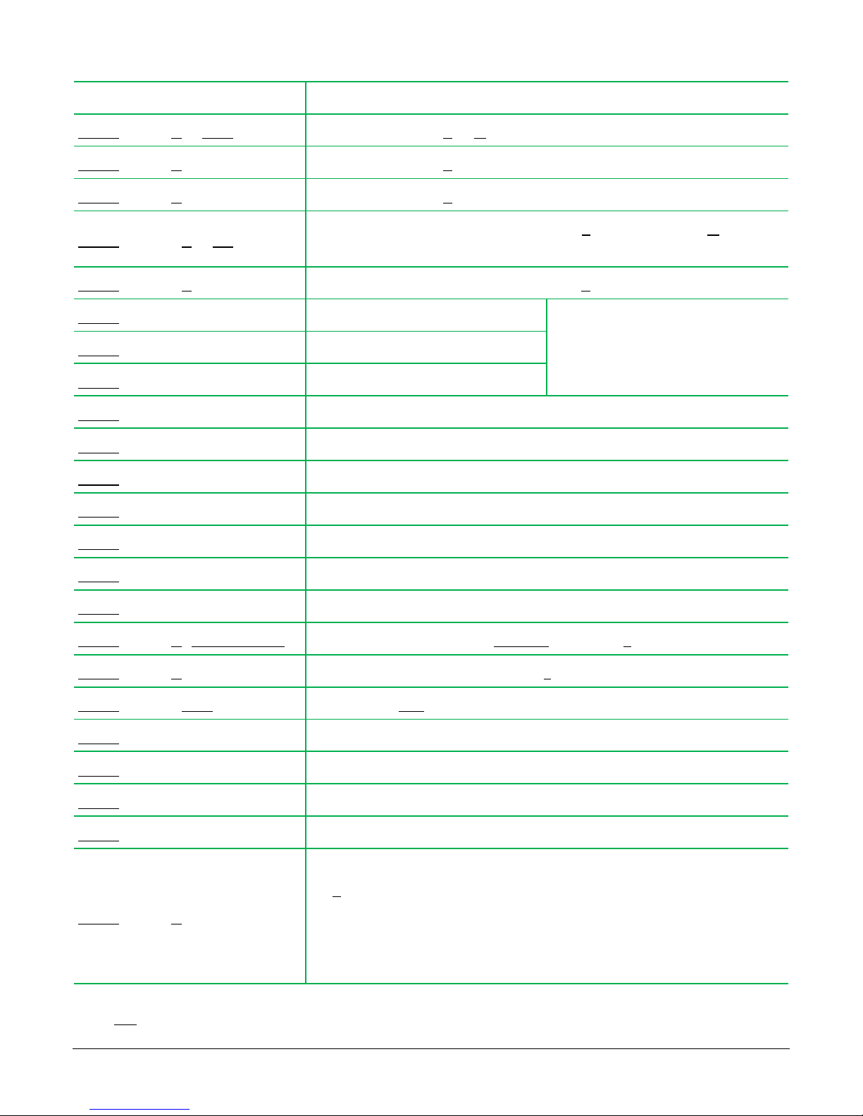
SMS commands list:
Command
Function
xxxx#out Nonttt
Switch on the relay AUX-N for ttt seconds (from 001 to 999)
xxxx#out Non
Switch on the relay AUX-N
xxxx#out Noff
Switch off the relay AUX-N
xxxx#temp NonTT
Start the heating control: switch on the relay AUX-N until temperature is TT grades, for
max 24 hours (then stop the control and switch off the relay)
xxxx#temp Noff
Stop the heating control: switch off the raley AUX-N
xxxx#instot
Total arming
The control panel replay with a confirm
SMS of remote arming, with indication of
opened doors (if present)
xxxx#inspar
Partial arming
xxxx#insext
External arming
xxxx#disins
Disarming
xxxx#stop
Stop calls: stop all the ongoing calls
xxxx#status
Display status of control panel and output relay
xxxx#signal
Display the GSM signal level
xxxx#listen
Environmental listening up to 5 minutes
xxxx#config
Display actual telephone number settings
xxxx#riccre
SIM credit request: control panel answers with a residual credit SMS
xxxx#num n yyyyyyyyy
Program the telephone number “yyyyyyyyyy” in position “n”
xxxx#del n
Delete the telephone number in position “n”
xxxx#scad DDD
Set the number DDD of days to send a memo of “SIM expiring”
xxxx#extincl
External sensors (E) included in Total and Partial arming
xxxx#extescl
External sensors (E) excluded in Total and Partial arming
xxxx#abilrem
Enable the remote communication (remote programming via GPRS)
xxxx#fineabilrem
Disable the remote communication
xxxx#eiv D
Time for send the “GSM modem in life” SMS
The D value set the time as follows:
D = 0 12 hours
D = 1 24 hours
D = 2 48 hours
D = 3 72 hours
D = 4 1 week
D = 5 1 month
where “XXXX” is the Remote Code.
Page 41

41
13.4. ADD TELEPHONE NUMBERS
Send one SMS for each number to add.
The SMS text must be:
xxxx#num n qqqqqqqqqqqq
where:
xxxx
Remote Code
n
Memory position (from 1 to 8)
qqqqqqqqq
Telephone number preceded by country code without the 00 (for UK is 44)
Example: Mr Rossi wants to program his own mobile number (333.44.44.444) in his new control panel CE 60-8 GSM, so that he
receives an alert in case of a burglary or other event, allowing him to manage the situation remotely.
He will send the control panel phone number, the following SMS:
0000#num 3 443334444444
The control panel Remote Code is “0000” (default).
The mobile phone number 333.44.44.444 (the digits 44 were put in before the number for calls from an U.K. phone) it will
be memorized in location number 3.
From this moment on Mr Rossi will be able to receive vocal calls or SMS from the control panel.
It is also possible to program the dialler to make calls to landlines.
THE MEMORY LOCATION NUMBER 1 IS SPECIAL AND CAN ONLY HAVE A GSM NUMBER (THE SIM EXPIRATION IS
ONLY SENT TO THIS NUMBER)
THE MEMORY LOCATIONS FROM 2 TO 8 CAN HAVE BOTH GSM AND LANDLINE NUMBERS
Example: In the case of an alarm Mr Rossi wants to receive calls, from the control panel, on a landline 011.77.55.333 (it could be the
number of a second home or his relatives); he will program (as he did in the previous example, via SMS) the control panel
with the number as follows:
0000#num 6 440117755333
13.5. DELETE TELEPHONE NUMBERS
xxxx#del n
To delete a telephone number stored in memory position “n”
13.6. EMERGENCY NUMBERS
It is possible to program public emergency numbers (example: 911) in the same way as the other numbers, just by OMITTING the international
country code:
Example: Mr Rossi would like to program the number to the Police:
0000#num 5 911
Page 42

42
13.7. PROGRAM SIM CREDIT REQUEST
Follows the SMS commands list the user can send to the control panel to set the SIM credit request (credit request can be done via SMS or
directly on front panel).
SIM CREDIT REQUEST DEPENDS ON NETWORK OPERATOR.
IT IS NOT POSSIBLE TO USE UMTS TYPE SIM.
SIM credit mode
Programming command
Example
Contract
xxxx#cre c
-
Rechargeable
Credit request by phone call to “yyyyyyyyyyy”
Answer from operator: SMS
xxxx#cre t yyyyyyyyyyy
0000#cre t 404
Rechargeable
Credit request by SMS to “yyyyyyyyyyy”
Answer from operator: SMS
xxxx#cre s yyyyyyyyyyy text
0000#cre s +40916 CREDIT
Rechargeable
Credit request by phone call to “yyyyyyyyyyy”
Answer from operator: flash message
xxxx#cre f yyyyyyyyyyy
0000#cre f *123#
13.8. SIM CREDIT REQUEST
xxxx#riccre
Start the SIM credit request with the telephone operator: the control panel with reply with an SMS of the
credit amount left. In the case of a failed connection, the control panel will send “No operator response try
again later”.
13.9. SET THE ALERT FOR SIM EXPIRING
Set the number of days after which the control panel will send an SMS alert for the SIM expiration. If the number of days is set to "0"(zero),
this service is disabled.
xxxx#scad yyy
Set a reminder for SIM expiration between yyy days
THE NOTICE OF SIM EXPIRATION WILL BE SENT FROM THE CONTROL PANEL ONCE ONLY (AT THE END OF TIME
SET) AND ONLY TO THE FIRST NUMBER STORED IN THE INTERNAL DIALLER
ONCE IT EXPIRES, IT IS NOT RESTORED AUTOMATICALLY; YOU WILL NEED TO MANUALLY RESET IT
Page 43

43
13.10. GENERAL NOTES ON COMMAND SMS
All the SMS sent from control panel contain a first row, which describes the event occurred and a second row with date and time of the event.
“Radio Zone 01 R
10:07 11/10/11”
Alarm events: the first row describes the event and contains the name of the zone (set via software) and the qualifier of the event (example:
opened door, roller, …).
The qualifiers are:
ALARM AUTO-EXCLUSION
TAMPER RADIO ZONE
ALARM CTSR ROLLER
MOSKITO FRONT SIDE
ALARM CTSR SHOCK
MOSKITO LEFT SIDE
ALARM CTSR EXTERNAL CONTACT
MOSKITO RIGHT SIDE
ALARM CTSR INTERNAL CONTACT
MOSKITO LEFT ELUSION
MISSED SUPERVISION
MOSKITO MASKING
LOW BATTERY RADIO ZONE
MOSKITO RIGHT ELUSION
“Special” events: these events use the text set in “Messages” tab of the software:
ALARM WIRED TAMPER
ALARM AC FAIL
ALARM RADIO BLINDING
ALARM AC RETURN
ALARM LOW BATTERY
ALARM BURGLARY
ALARM BATTERY RESTORE
Status events: the first row contains the activator name (set via software) and a letter which describes the arming type:
T = Total
E = External
P = Partial
D = Disarmed
Activators “special” events: these events use the text set in “Messages” tab of the software:
PANIC
COERCION
SILENT ALARM
SIM EXPIRING
SUPERVISION SMS SENDING
In case of errors: as response to SMS sent by users, are sent these error SMS:
Error: NO Valid Command
The command is not typed correctly
If the Contact-ID GPRS fails, is sent an error SMS with the event to
the telephone number (if set)
Error: NO Valid Code
The Remote Code is wrong
Event row
Date and time
Page 44

44
It is possible to set which events the panel must send to each telephone number:
“Alarm SMS”: all the alarm messages
“Silent Alarm SMS”: events related to Silent Alarm and Coercion
“Power Status SMS”: all the events related to low batteries, AC
power fail and back AC power
“Abil. Tx Stato Ins”: events related to system arming status changes
“Panic SMS”: events related to panic actions
If the “provider telephone number” is set (software, “SIM Options” tab), all the SMS received from this number are forwarded to the first
telephone number in memory.
13.11. SMS CREATION SYNTAX
Main data: [Time] (format: “hh:mm”) [Date] (format: “dd/mm/yy”)
Alarm events
[Zone name] + [Zone type] + [Alarm event] + [Time] + [Date]
Format
Notes
[Zone name]
“Radio Zone xx” [xx = 01 ÷ 60]
or:
“Wired Zone yy” [yy = 01 ÷ 03]
The installer can customize these texts
via software
[Zone type]
“(R)” Delayed
“(I)” Instantaneous
[Alarm event]
“Auto-exclusion” “CTSR Internal”
“CTSR Roller” “SPV Missed”
“CTSR Shock” “LWB”
“CTSR External” “Tamper”
The installer can customize these texts
via software
Example: Radio Zone 01 R
10:07 11/10/11
Special alarm events
[Special alarm event] + [Time] + [Date]
Format
Notes
[Special alarm
event]
“Wired tamper” “Battery restored”
“Blinding” “AC power fail”
“Low Battery” “AC power restore”
The installer can customize these texts
via software
Example: Blinding
21:10 12/10/11
Page 45

45
System status events (system arming)
[Activator name] + [Arming type] + [Time] + [Date]
Format
Notes
[Activator name]
“Activator xx”
xx = 01 ÷ 24
The installer can
customize these texts via
software
[Arming type]
“T” Total “E” External
“P” Partial “D” Disarmed
Example: Activator 01 T
18:20 13/10/11
Activators special events
[Activator special event] + [Time] + [Date]
Format
Notes
[Activator special
event]
“Panic” “Coercion”
“Silent Alarm” “SIM expiring”
“Supervision SMS”
The installer can customize these texts
via software
Example: Supervision SMS
21:04 12/10/11
Page 46

46
14. VOICE MENU
IF A RELAY AUX OUTPUT IS SET AS “RING”, THE VOICE MENU IS DISABLED
Calling the telephone number of the control panel, a voice answer with a list of options: select the wanted action and digit the combined
number on the telephone.
It is possible to set the panel to answer calls after a certain number of “rings” (RING NUMBER, selectable from 1 to 9).
Voice Menu items list:
Button
Action
Reference for customization:
0
Arming status
Tech message 04
1
Disarming
Tech message 05
2
Arm: TOTAL
Tech message 06
3
Arm: PARTIAL
Tech message 07
4
Arm: External/ Outdoor
Tech message 08
8
Environment listening (max 2 minutes)
Tech message 09
9
SIM credit request
Tech message 11
For details about available options in Voice Menu, refer to USER MANUAL.
Page 47

47
15. POWER SIGNALLINGS
The control panel continuously monitors the power status of the 230 VAC, of the backup battery and the on-board sensors battery stored in
the control panel.
NO POWER LINE 230 VAC
CONTROL PANEL BATTERY
SENSORS BATTERIES
DISPLAY
“AC power fail”
+
L1 red LED blinks
+
L3 green LED off
“Low Battery”
+
L1 red LED blinks
(no advice on display at battery
restore)
“Low Battery”
+
L1 red LED blinks
SMS
“AC power fail” and “AC power
restore”
-
“Zone name”
+
“LWB” (low-battery)
ALARM MEMORY
“AC power fail” and “AC power
restore”
“Low Battery”
Name of the zone marked with
“LWB”
Page 48
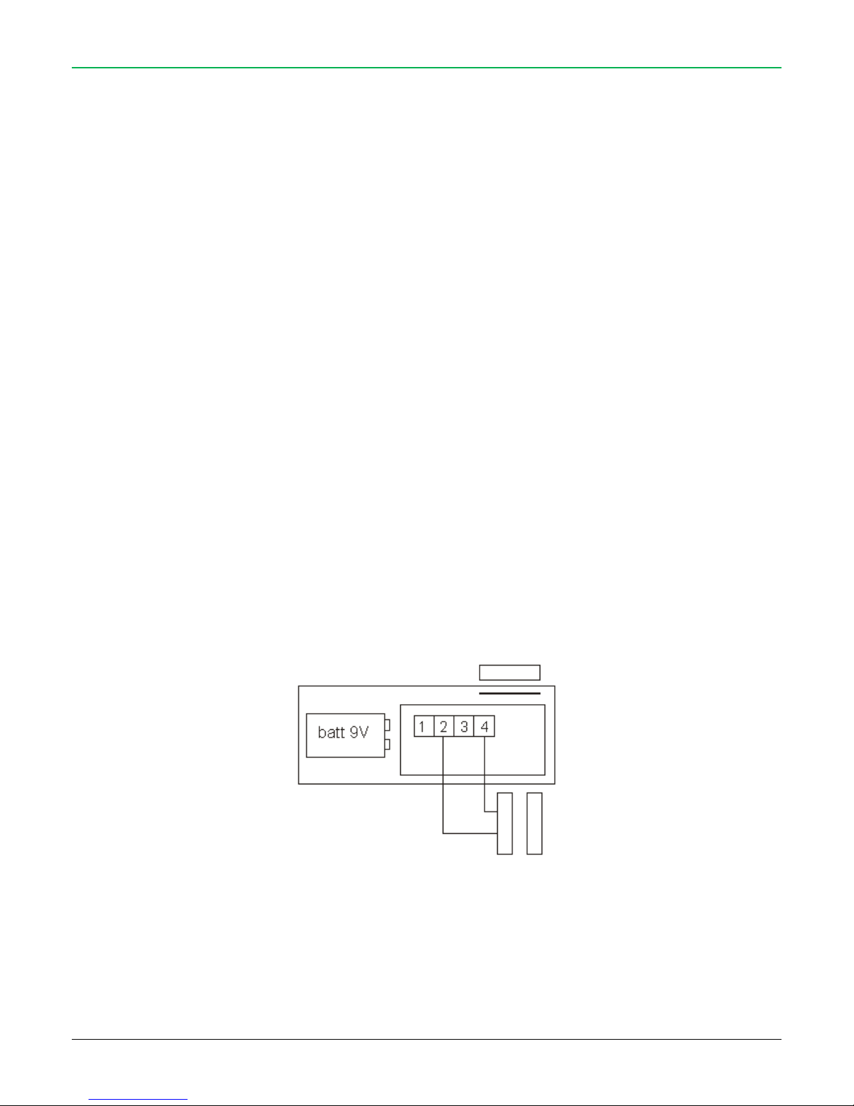
48
16. OPENED DOOR SIGNALLING
The CE 60-8 can advise the user if a door is left opened. To activate this signalling, the installer must enable the “Door control” function in
INSTALLER MENU (or via software)
16.1. WHEN THE FUNCTION IS DISABLED
When disarmed, the control panel does not signal any opened doors.
During arming (Total, Partial or External) there will be no warning and any opened zone will be bypassed.
At system armed, if an opened zone bypassed is closed, that zone will be automatically activated. From now on, if this zone is violated the
control panel starts alarm.
16.2. WHEN THE FUNCTION IS ENABLED
When disarmed, the control panel signals “opened door” by blinking the yellow LED (L2) when one or more wired zones and one or more
radio zones with MINI-C / CTSR sensor models are opened.
During arming (Total, Partial or External) the control panel alerts that there are opened doors with an acoustic sound for 10 seconds within
it is necessary to act in one of the following way (otherwise starts alarm):
close the opened door within the signalling time and exit time;
stop the arming with an activator.
The control panel will display “OPENED DOORS”: press the “#” button to read the opened zones list.
Confirm again the arming with an activator.
The control panel does not generate alarm and finish arming (Total, Partial or External) bypassing the opened zones.
The opened door signalling from radio zones is given to control panel by MINI-C and CTSR sensor models (see SOFTWARE MANUAL, “Radio
Zones Setting”):
when both contacts (onboard reed + external reed) are opened at the arming (“Single Contact” option is disabled);
when only the onboard reed contact is opened at the arming (“Single Contact” option is enabled).
REED contact scheme for CTSR sensor model
REED
2° contact
External contact
Page 49

49
17. CONTACT ID
The control panel support the Contact ID protocol.
The system is compatible with SIA DC09 standard.
FOR DETAILS ABOUT CONTACT-ID SEE SOFTWARE MANUAL ON CD
Page 50
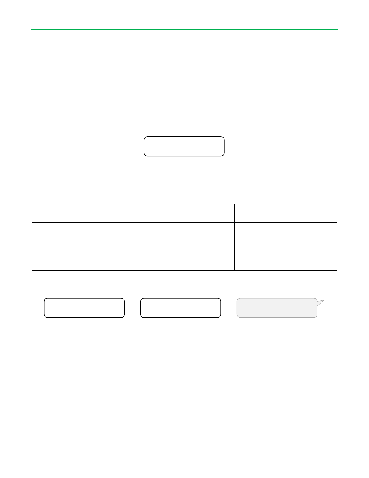
50
18. RADIO BLINDING AND RADIO SATURATION
The control panel has a monitoring system to detect if there are anomalies in the radio environment.
BY FACTORY SETTINGS, THE CONTROL PANEL HAS THE RADIO BLINDING DISABLED (blinding level = 0)
18.1. RADIO BLINDING
The control panel – in case of radio blinding attempt – can generate alarm.
The blinding monitor is active only at system armed in TOTAL mode, it is disabled in case of PARTIAL and EXTERNAL armings.
Furthermore, the blinding control starts after 15 seconds from the end of Exit Time.
Activate – in Installer Menu, during the “Radio Saturation Radio” test or via software – the Radio Blinding function:
The alarm starts if – within a certain time – the panel receives a relevant quantity of radio noise. The radio control consists in a real time
evaluation of two signal components: ANALOGIC and DIGITAL.
There are four blinding control levels.
Level
Sensitivity
ANALOGIC control
(max time, level limit)
DIGITAL control
(max time, level limit)
0
ANTI-BLINDING OFF - -
1
HIGH
20 seconds, 10
60 seconds, 2000
2
MEDIUM
30 seconds, 20
60 seconds, 6000
3
LOW
30 seconds, 25
60 seconds, 9000
4
VERY LOW
60 seconds, 52
180 seconds, 20000
The event is signalled with:
18.2. RADIO SATURATION TEST
The control panel can analyse the radio environmental “quality”.
In fact – in the installation environment there may be one or more radio emitting sources (temporary and/or continued, intentional or not)
with the same operating frequency of the panel. The radio signals emitted can interfere with the communication system of the control panel,
causing “blinding”.
The control panel can detect the presence of strong radio signals and determine if they are compromising the proper functioning of the
system.
Blinding Level
0 ÷ 4
Blinding
Blinding
Blinding
DISPLAY
LOG
SMS
Page 51
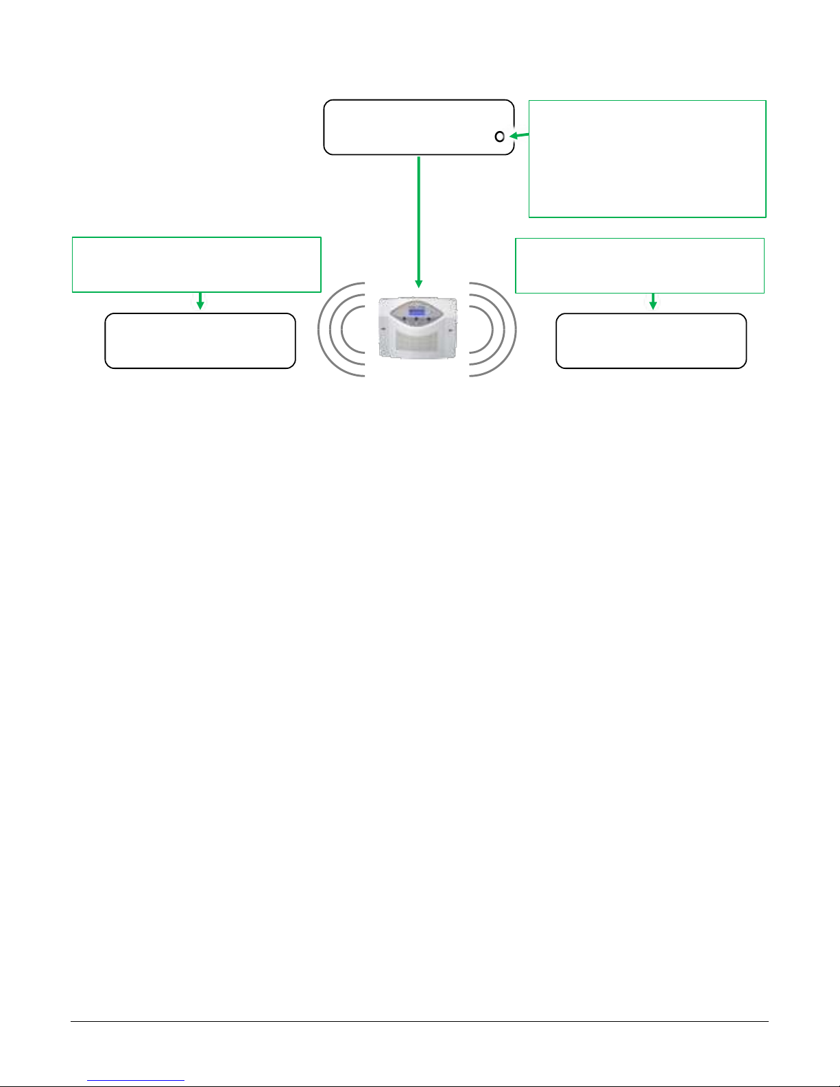
51
Activating this mode from the USER MENU or INSTALLER MENU the display will indicate (for the duration of the testing) the amount reached
by the digital counter (CNT) and the level in real time of power from radio waves received (RX):
This feature is enabled/disabled either from the user menu or from the installer menu: when started, the function remains active, switching
off automatically after 2 hours.
The control panel continues to operate normally even in testing: you can arm and disarm.
This test generates a special acoustic alert for about 30 seconds in case of “blinding” detection.
Cnt=00255 Rx= 57
Disarmed ▄ O
Radio Blinding
Digital
Radio Blinding
Analogic
Blinding level: 0 = disabled
1 = high 3 = low
2 = medium 4 = very low
To change the blinding level, press the “#”
button
Digital Blinding Alarm
CNT reached the value 5500 within 60 s
Analogic Blinging Alarm
RX exceeded the value 170 for more than 20s
Page 52

52
Made in Italy
This device meets the R&TTE requirements (European Union)
 Loading...