

Page 1
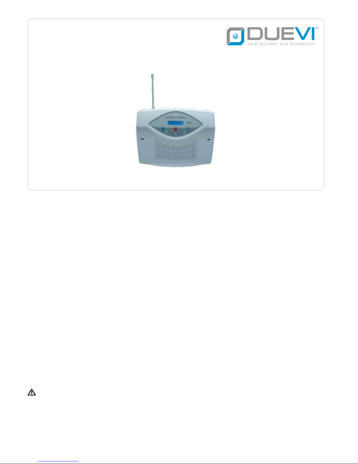
IN THIS MANUAL ARE SHOWN ALL THE FUNCTIONS OF CE60-8GSM AND CE60-8 CONTROL PANELS. THE CE60-8
PANEL DIFFERS FROM CE60-8GSM FOR THE ABSENCE OF INTEGRATED GSM MODULE.
THUS, ALL THE FUNCTIONS RELATED TO GSM MODULE USE DOES NOT APPLY TO CE60-8 PANEL.
CE60-8GSM / CE60-8
WIRELESS/WIRED BI-DIRECTIONAL CONTROL PANEL
[AN] [SPV] [48 bit] [Series 100] User Manual 16.02-MU:1.1-H:x.x-F:1.0.3-S:1.0.3
Page 2

2
INDEX
1. INTRODUCTION ....................................................................................................................................................................................... 4
2. FRONT PANEL: DISPLAY AND BUTTONS .................................................................................................................................................... 5
2.1. LED ................................................................................................................................................................................................ 5
2.2. BUTTONS ....................................................................................................................................................................................... 5
2.3. DISPLAY .......................................................................................................................................................................................... 5
3. USE OF THE PANEL .................................................................................................................................................................................. 6
3.1. ARMINGS ....................................................................................................................................................................................... 6
3.2. TOTAL ARMING ............................................................................................................................................................................... 7
3.3. DISARM/STOP ALARMS ................................................................................................................................................................... 8
3.4. ALARMS MEMORY .......................................................................................................................................................................... 8
3.5. EVENTS LOG ................................................................................................................................................................................... 8
3.6. PARTIAL ARMING ............................................................................................................................................................................ 9
3.7. EXTERNAL ARMING ......................................................................................................................................................................... 9
3.8. TAMPER ALARM ............................................................................................................................................................................ 10
4. TEMPERATURE AND SYSTEM VERSION ................................................................................................................................................... 10
5. PANEL TEST ........................................................................................................................................................................................... 10
6. FUNCTIONS ........................................................................................................................................................................................... 11
6.1. EXIT TIME ..................................................................................................................................................................................... 11
6.2. ENTRY TIME .................................................................................................................................................................................. 11
6.3. ALERT ........................................................................................................................................................................................... 11
6.4. PRE-ALARM TIME .......................................................................................................................................................................... 11
6.5. PANEL TEST .................................................................................................................................................................................. 12
6.6. TAMPER ....................................................................................................................................................................................... 12
6.7. LOW BATTERY ............................................................................................................................................................................... 12
6.8. TECHNOLOGIC ZONES .................................................................................................................................................................. 12
6.9. OPENED DOORS ALERT ................................................................................................................................................................. 12
6.10. ANTI-BLINDING ........................................................................................................................................................................ 13
6.11. CONTACTID .............................................................................................................................................................................. 13
6.12. INCLUDE/EXCLUDE EXTERNAL ZONES ........................................................................................................................................ 13
6.13. EXTERNAL ZONES ALARM/RING ................................................................................................................................................ 14
6.14. GSM ANTI-JAMMING ................................................................................................................................................................ 14
7. TEMPERATURE CONTROL FUNCTION ...................................................................................................................................................... 15
8. MODEM MENU / CREDIT REQUEST ........................................................................................................................................................ 16
9. USER MENU .......................................................................................................................................................................................... 17
9.1. ENTER THE USER MENU ................................................................................................................................................................ 17
9.2. USER MENU ITEMS ....................................................................................................................................................................... 17
9.3. DATE AND TIME ............................................................................................................................................................................ 17
9.4. REMOTE CODE ............................................................................................................................................................................. 18
9.5. DELETE ACTIVATOR ........................................................................................................................................................................ 18
9.6. ALERT PROGRAM .......................................................................................................................................................................... 18
9.7. TEMPORARY EXCLUSION PROGRAM .............................................................................................................................................. 18
9.8. VOICE MESSAGES PROGRAM ........................................................................................................................................................ 19
Page 3

3
9.9. ARM/DISARM BEEP ...................................................................................................................................................................... 19
9.10. EXTERNAL ZONES BEEP/ALARM................................................................................................................................................. 20
9.11. SIREN TEST ............................................................................................................................................................................... 20
9.12. RADIO SATURATION .................................................................................................................................................................. 20
9.13. EXIT PROGRAMMING ............................................................................................................................................................... 20
10. VOICE MENU .................................................................................................................................................................................... 21
10.1. VOICE MENU OPTIONS ............................................................................................................................................................. 22
11. GSM: FUNCTIONS AND PANEL MANAGEMENT .................................................................................................................................. 24
11.1. FACTORY SETTINGS ................................................................................................................................................................... 24
11.2. CONTROL PANEL ACTIONS/REACTIONS ..................................................................................................................................... 25
11.3. ADD TELEPHONE NUMBERS ..................................................................................................................................................... 26
11.4. DELETE TELEPHONE NUMBERS ................................................................................................................................................. 26
11.5. PANEL MANAGEMENT SMS COMMANDS ................................................................................................................................. 27
11.6. EMERGENCY NUMBERS ........................................................................................................................................................... 28
11.7. ASK FOR SIM CREDIT ................................................................................................................................................................ 28
11.8. SET THE ALERT FOR SIM EXPIRING ............................................................................................................................................ 28
11.9. GENERAL NOTES ABOUT SMS ................................................................................................................................................... 28
11.10. SMS SYNTAX ............................................................................................................................................................................. 29
12. BLOCK ONGOING CALLS ................................................................................................................................................................... 30
13. ACCESSORIES .................................................................................................................................................................................... 31
13.1. EMERGENCY REMOTE CONTROL ............................................................................................................................................... 31
13.2. KEYBOARD ................................................................................................................................................................................ 31
14. POWER ALERTS ................................................................................................................................................................................. 31
14.1. WIRELESS ZONES LOW BATTERY ............................................................................................................................................... 31
14.2. CONTROL PANEL LOW BATTERY ................................................................................................................................................ 31
14.3. AC POWER FAIL ........................................................................................................................................................................ 31
15. ZONES DESCRIPTION ......................................................................................................................................................................... 32
Page 4
4
1. INTRODUCTION
The CE 60-8 GSM is a microprocessor alarm control panel for wireless systems, which integrates on-board a GSM phone dialler.
THE INSTALLATION OF THE PRODUCT MUST BE DONE BY QUALIFIED TECHNICIAN DUE TO REALIZATION OF
POLARIZED ELECTRICAL CONNECTIONS WITH A CONSEQUENT RISK OF SHORT CIRCUIT.
THE INSTALLER MUST FOLLOW THE REGULATION.
SAFETY AND MAINTENANCE TIPS
DO NOT CLEAN THE BOX WITH ALCOHOL OR OTHER CHEMICAL CLEANERS, BUT ONLY WITH A DAMP CLOTH.
IN CASE OF FAILURE DO NOT TRY TO REPAIR BY YOURSELF THE CONTROL PANEL BUT CALL THE NEAREST AUTHORIZED
TECHNICAL ASSISTANCE CENTER.
DURING THE TESTS, USE A CLOTH ON THE INDOOR SIREN IN ORDER TO LOWER THE SIREN SOUND.
THESE PRODUCTS ARE NOT TOYS. KEEP OUT OF REACH OF CHILDREN.
PLEASE NOTE THAT THIS DEVICE IS AN ALARM SYSTEM SO IT DETECTS THE PRESENCE OF AN INTRUDER AND
ACTIVATES THE SIRENS.
IN CASE OF ALARM, A PROMPT INTERVENTION IS REQUIRED IN ORDER TO PREVENT THEFT OR DAMAGE OF
PROPERTIES (FOR THIS REASON IT IS APPROPRIATE TO GET INSURANCE).
THE COMPANY DISCLAIMS ANY LIABILITY FOR THEFT OR DAMAGE.
THE COMMUNICATION BETWEEN THE INSTALLATION COMPONENTS IS DONE BY RADIO FREQUENCY. BEFORE THE
FINAL INSTALLATION, BE SURE THAT THE CONTROL PANEL COMMUNICATES SUCCESSFULLY WITH ALL THE DEVICES.
IN FACT, IT COULD HAPPEN THAT THE CONTROL PANEL DOES NOT RECEIVE THE CORRECT SIGNALS FROM SOME OF
THE SENSORS. THIS CAN BE DUE TO ENVIRONMENTAL FEATURES IN WHICH THE SYSTEM WORKS: CONCRETE WALLS,
METAL BOXES, METAL SHELVES, ETC… CAN CREATE PARTICULAR CONDITIONS LIKE SIGNAL REFRACTION OR
REDUCTION (FOR EXAMPLE AS THERE CAN BE INSUFFICIENT RECEPTION OF A MOBILE PHONE IN CERTAIN AREAS).
TO AVOID THESE INCONVENIENCES AND OBTAIN ALWAYS THE BEST PERFORMANCE FROM YOUR SYSTEM, PLEASE
ALWAYS PERFORM SOME PRELIMINARY POSITIONING TESTS IN ORDER TO VERIFY THE EFFECTIVENESS OF THE RADIO
TRANSMISSION.
THE COMPANY IS NOT RESPONSIBLE IN CASE OF IMPROPER USE OF THE PRODUCT, WRONG INSTALLATION OR
INOBSERVANCE OF THE INSTRUCTIONS INDICATED IN THIS GUIDE OR INOBSERVANCE OF THE ELECTRICAL
INSTALLATION REGULATION.
Page 5
5
2. FRONT PANEL: DISPLAY AND BUTTONS
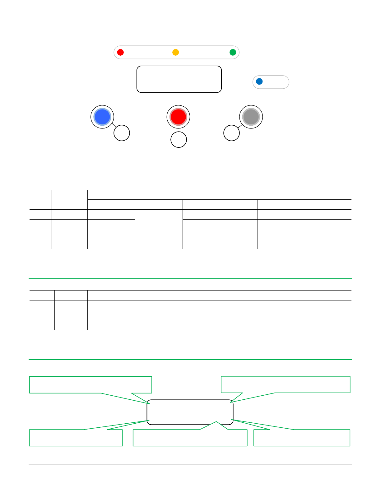
2.1. LED
LED
Colour
Signalling
Solid on
Blinking
Off
L1
RED
Total arming
External arming
Alarm memory
-
L2
YELLOW
Partial arming
Opened door alert
-
L3
GREEN
Power line present
-
No power 230 VAC
ALERT
BLUE
ALERT on
Radio code transmission
ALERT off
2.2. BUTTONS
Button
Function
X
Options
Include-exclude External Zones / User Menu / Alert
O
Selection
Alarm memory / GSM Menu / Credit request
#
Menu
Control panel version / Panel test / Scroll
2.3. DISPLAY
The control panel shows (when disarmed and without special events) on LCD display:
CE608 ver. 1.0.3
CED 07/15
L1
L2
L3
ALERT
X
#
O
12:30 06/02/16 ▄
Disarmed ▄ O
Date and Time
Radio signal level received
Arming status
GSM signal level (if available)
External zones excluded/included
Page 6
6
3. USE OF THE PANEL
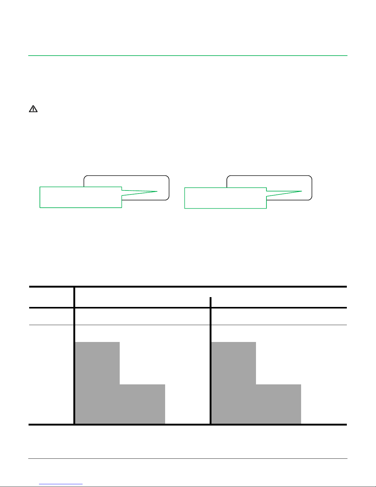
3.1. ARMINGS
Each zone can be programmed to be associated to only one of the three arming types [T=Total, P=Partial, E=External]:
TOTAL Zones included: T + P + E or T + P (if E are excluded)
PARTIAL Zones included: P + E or P (if E are excluded)
EXTERNAL Zones included: E (even if E are excluded from T and P armings)
IF NO SENSOR IS SET AS T, P OR E, THE CORRESPONDING ARMING IS NOT EXECUTED
The sensors programmed as EXTERNAL (E) can be excluded from Total and Partial arming:
wait for 2 minutes from the last disarming
hold down the “X” button of the control panel
the status of the inclusion/exclusion of the sensors E (“excluded included” or “included excluded”) changes and is displayed.
on display - at rest – changes the indication:
The control panel records and maintains the status of the exclusion that has been set. To change it repeat the procedure.
Alarm > High powered sound from indoor and outdoor siren. Duration: 3 minutes (can be modified)
Prealarm > (to enable if desired) Acoustic warning from indoor siren before the alarm. Duration: 60 seconds (can be modified)
Ring > (only from outdoor sensors) Acoustic warning from indoor siren. Duration: 60 seconds (can be modified)
External Zones Included
Arming
Actions of the control panel in case of violation
External Zones Ring ON
External Zones Ring OFF
Total zones
Partial zones
External zones
Total zones
Partial zones
External zones
TOTAL
Alarm
(3 minutes)
Alarm
(3 minutes)
Ring
(60 seconds)
Alarm
(3 minutes)
Alarm
(3 minutes)
Alarm
(3 minutes)
PARTIAL
Not active
Pre-alarm
(0-60 seconds)
+
Alarm
(3 minutes)
Ring
(60 seconds)
Not active
Pre-alarm
(0-60 seconds)
+
Alarm
(3 minutes)
Pre-alarm
(0-60 seconds)
+
Alarm
(3 minutes)
EXTERNAL
Not active
Not active
Ring
(60 seconds)
Not active
Not active
Pre-alarm
(0-60 seconds)
+
Alarm
(3 minutes)
12:30 06/02/16 ▄
Disarmed ▄ X
12:30 06/02/16 ▄
Disarmed ▄ O
“O”: the sensors E are included
in Total and Partial
“X”: the sensors E are excluded
from Total and Partial
Page 7

7
TOTAL arming
Press once the BIG button of the
remote control
Pass once the CHT key
Arm with the radio keyboard
External Zones Excluded
Arming
Actions of the control panel in case of violation
External Zones Ring ON
External Zones Ring OFF
Total zones
Partial zones
External zones
Total zones
Partial zones
External zones
TOTAL
Alarm
(3 minutes)
Alarm
(3 minutes)
Not active
Alarm
(3 minutes)
Alarm
(3 minutes)
Not active
PARTIAL
Not active
Pre-alarm
(0-60 seconds)
+
Alarm
(3 minutes)
Not active
Not active
Pre-alarm
(0-60 seconds)
+
Alarm
(3 minutes)
Not active
EXTERNAL
Not active
Not active
Ring
(60 seconds)
Not active
Not active
Pre-alarm
(0-60 seconds)
+
Alarm
(3 minutes)
EXTERNAL ARMING DOES NOT CONSIDER THE EXCLUSION OF THE ZONES E.
EXTERNAL ARMING ALWAYS ACTIVATES THE ZONES E FOR THE ALARM DETECTION.
3.2. TOTAL ARMING
The system is TOTALLY activated (red LED L1 lights on) when you want to arm the control panel detecting violations and entering, whenever any
zone (excluded the ones excluded) detects a movement.
This type of arming is normally used when you are out of the house.
All zones detecting breakings and entering will activate the sirens (internal and external).
The alarm period is 3 minutes for each event, and it can be repeated up to 4 times for the signal coming from a single sensor during the same
arming time, and anyway up to a 10 times maximum.
See the behaviour in case of open doors in the next related chapter.
Always verify in the display that the Outdoor sensors are included (“O” symbol) or excluded (“X” symbol).
12:30 06/02/16 ▄
Total Armed ▄ X
Page 8
8
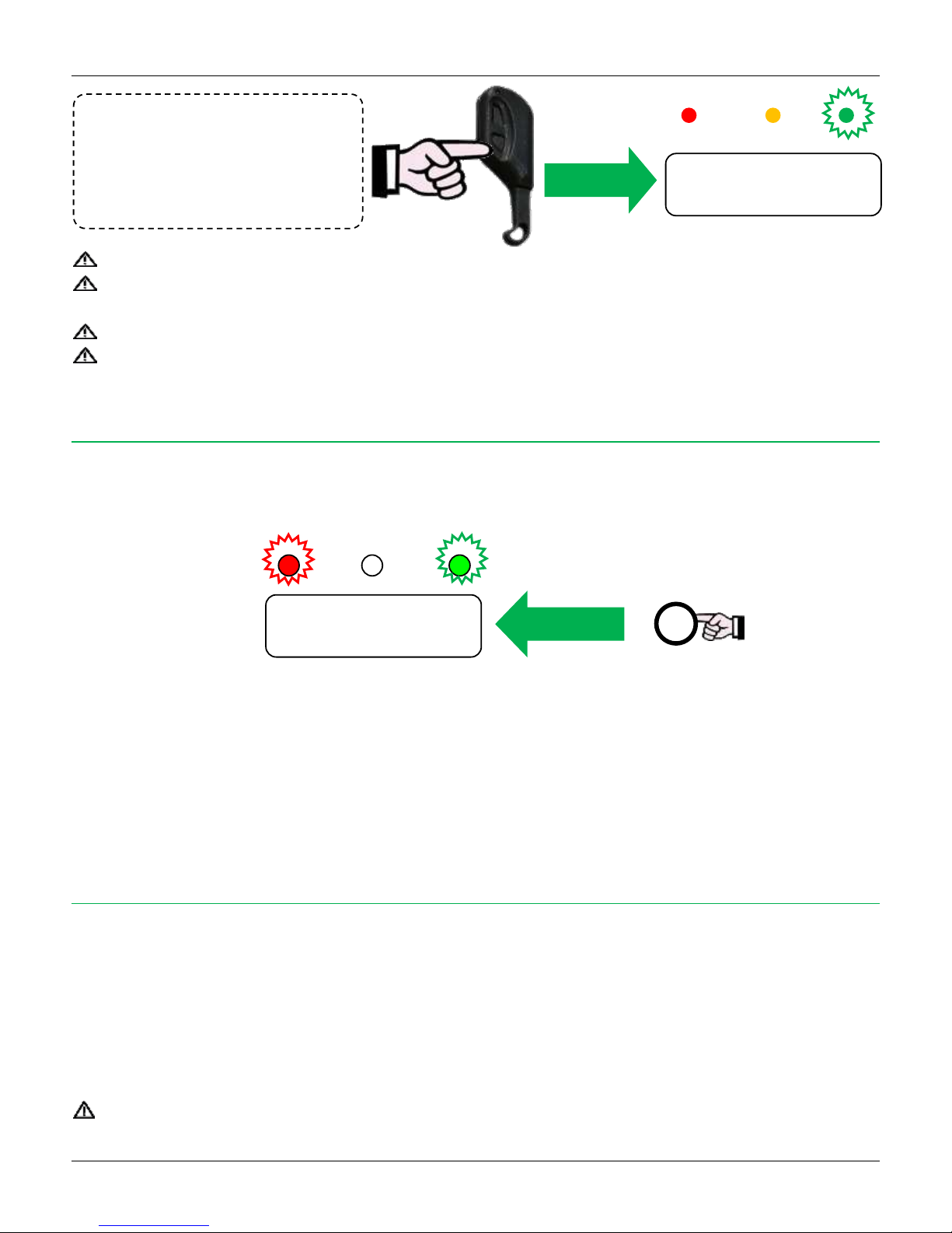
Disarming
Press once the SMALL button of the
remote control
Pass once the CHT key
Disarm with the keyboard
3.3. DISARM/STOP ALARMS
The disarming stops immediately all the calls and the SMS sending.
In case of alarm, at disarming the control panel shows on display the presence of “Alarm Memory” (see the “ALARMS MEMORY”
paragraph)
Within 2 minutes from disarming, the TAMPER alarms are disabled.
Within 1 minute from disarming, it is possible to access to User Menu (hold down the “X” button)
3.4. ALARMS MEMORY
The control panel is provided with a recording and visualization function of the sensors generating alarm. After an alarm event, at the disarming
and in event of alarms, the control panel will emit a series of fast “beeps”.
The red LED L1 will flash and “Alarms Memory” will appear in the display.
At this point, pressing few times the “O” button it is possible to see chronologically the memory of the last occurred events, to verify the sensor
or the sensors that generated the alarm.
The end of the events list is indicated with some “beeps”. To exit press briefly the “#” button.
DELETING THE ALARMS MEMORY > To delete hold down for few seconds (while you are in the Alarm Memory) the “#” button until you'll
hear some “beeps” as confirmation (the red LED L1 switches off).
3.5. EVENTS LOG
The Events Log contains the chronological list (from the newest) of the last 100 events occurred in the control panel.
To see the Events Log:
when the control panel is disarmed, press for a long time the “O” button
the “GSM Modem / SIM Credit” menu opens
scroll (with the “#” button) until the entry “Event Log”: the control panel emits few “beeps” and shows the first event of the list
to see the next event press the “O” button
after the last event, the control panel emits few “beeps”, “Event Log” appears in the display and, after that, the events list starts again.
press “#” to exit
IF THE EVENTS LOG IS EMPTY, IT DOES NOT APPEAR IN THE “GSM MODEM / SIM CREDIT” MENU
12:30 06/02/16 ▄
Disarmed ▄ X
Blinking
L1 L2 L3
O
12:30 06/02/12 ▄
Alarm Memory
Page 9
9
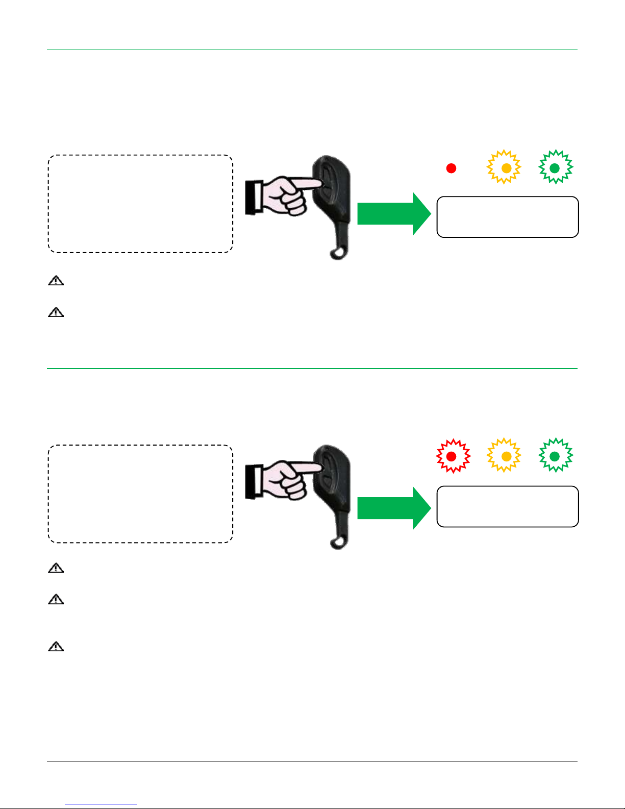
PARTIAL arming
Press twice the BIG button of the
remote control
Pass twice the CHT key
Arm with the Keyboard
OUTDOOR Arming
Press 3 times the BIG button of the
remote control
Pass 3 times the CHT key
Arm with the Keyboard
3.6. PARTIAL ARMING
The PARTIAL arming (yellow LED L2 lights on) is useful if you are interested in activating just a certain number of sensors (set up as PARTIAL
and/or EXTERNAL).
A classic example of partitioning is the definition of the perimeter zone; it is to say grouping all sensors defending the perimeter of the protected
area (on-doors sensors, windows and shutters, garden).
For example, at night, when the user is at home (and therefore he should not be detected), it is necessary to check only doors and windows
(environmental perimeter). In this type of arming infrared sensor are not working.
See the behaviour in case of open doors in the next related chapter.
Always verify in the display that the Outdoor sensors are included (“O” symbol) or excluded (“X” symbol).
3.7. EXTERNAL ARMING
The EXTERNAL arming is a special arming mode in order to activate exclusively a detecting area outside the building (zones E); the sensors T
(perimeter) and P (indoor) will not be activated and will not report alarm or intrusion in case of activity within the areas controlled by them.
For example, it can be used when the user likes to move freely within the building being sure of the presence of an alarm in case of any potential
intrusion from the outside (area controlled by External zones).
The sensors E will be activated even if their exclusion is set: the exclusion is valid only for Total and Partial arming).
If the function “External Zones Ring” is been activated, the sensors set up as External, if violated, will only cause a 60 seconds beeps.
If the function “External Zones Ring” is been deactivated, the External zones will generate alarm in case of detection..
See the behaviour in case of open doors in the next related chapter.
12:30 06/02/16 ▄
Partial Arm. ▄ X
12:30 06/02/16 ▄
External Arm ▄ X
Page 10
10
3.8. TAMPER ALARM
The internal tamper control works 24h/24 (even at disarmed system).
The external tamper (or wired) towards the zones works 24h/24 (even at disarmed system).
In case of tamper event:
The acoustic signal starts (for the programmed time) on internal siren and external siren (if present).
The series of voice calls and the SMS alarm starts (if programmed).
THE TAMPER ALARM, IF HAPPENS, IS EXECUTED JUST ONCE FOR THE ARMING CYCLE, AFTER THAT IT IS DISABLED
UNTIL THE DISARMING.
THEREFORE, THE TAMPER ALARM IS RE-ENABLED AT THE NEXT ARMING.
4. TEMPERATURE AND SYSTEM VERSION
The display shows:
control panel firmware version.
real time measured temperature (only with the optional temperature probe installed).
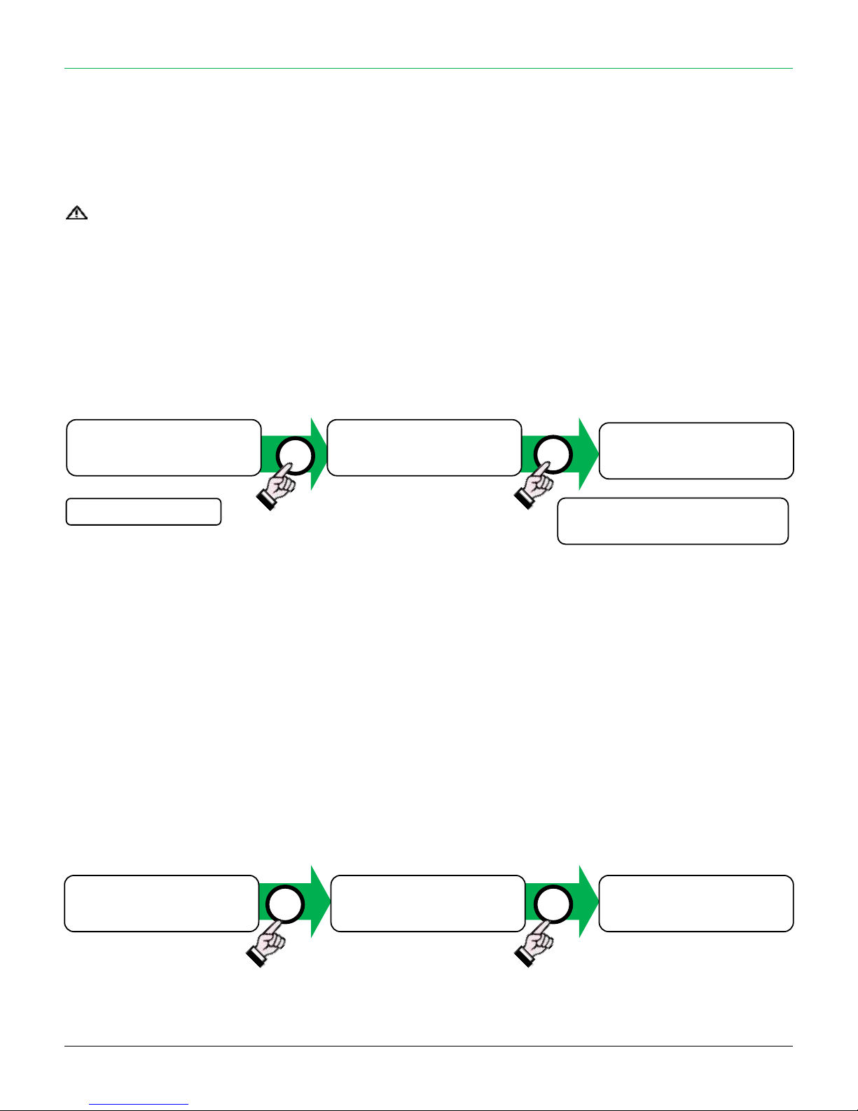
5. PANEL TEST
To enter in “Panel Test”:
1. Disarm the panel (even if already disarmed)
2. Hold down the “#” button until appears “Panel Test” on display
This test allows to verify if the activators (keys, remote controls or keyboard users) and the wired/wireless zones communicate correctly with the
control panel. The panel shows on display the name of the device/zone activated and emitting a “beep”, confirming the communication.
To exit from “Panel Test” hold down the “#” button or wait the panel exit (about 2 minutes).
#
Press short
#
Press short to back in normal
mode or wait some seconds.
12:30 06/02/16 ▄
Disarmed ▄ O
12:30 06/02/16 ▄
Disarmed ▄ O
Ce608 v1.0 26°
CE 07/16
#
#
12:30 06/02/12 ▄
Disarmed ▄ X
12:30 06/02/12 ▄
Disarmed ▄ X
Panel Test
Radio Zone 02 P
Page 11
11
6. FUNCTIONS
6.1. EXIT TIME
It is the time passing from the moment that the arming command is transmitted from an activator to the time when the system is effectively
armed. In fact, from the arming command, the system will be effective only after the exit time is finished without any detection occurred.
AUTO-EXCLUSION > if during the exit time a sensor detects a presence, the counting starts again from zero. If the same sensor restarts for 5
times the counting then it is automatically excluded (in Alarms Memory it is indicated with the name followed by the “=” symbol).
The exit time (adjustable by the installer) allows to verify the arming of the system through acoustic signals and the information shown in the
control panel display (that could be positioned far from the entrance door of the house) and allows having enough time to go out.
6.2. ENTRY TIME
It is the time passing from the moment that a delayed sensor detects an intruder to the effective alarm start through the sirens. This time can be
activated or not on each sensor (by the installer). It is possible to change its duration.
This time allows, for example, the entrance from a delayed entrance in order to reach the control panel and disarm it without generating alarm.
If the system is not disarmed within the programmed entry time, the control panel will generate alarm. It is a useful function if the control panel
is positioned far from the entrance door.
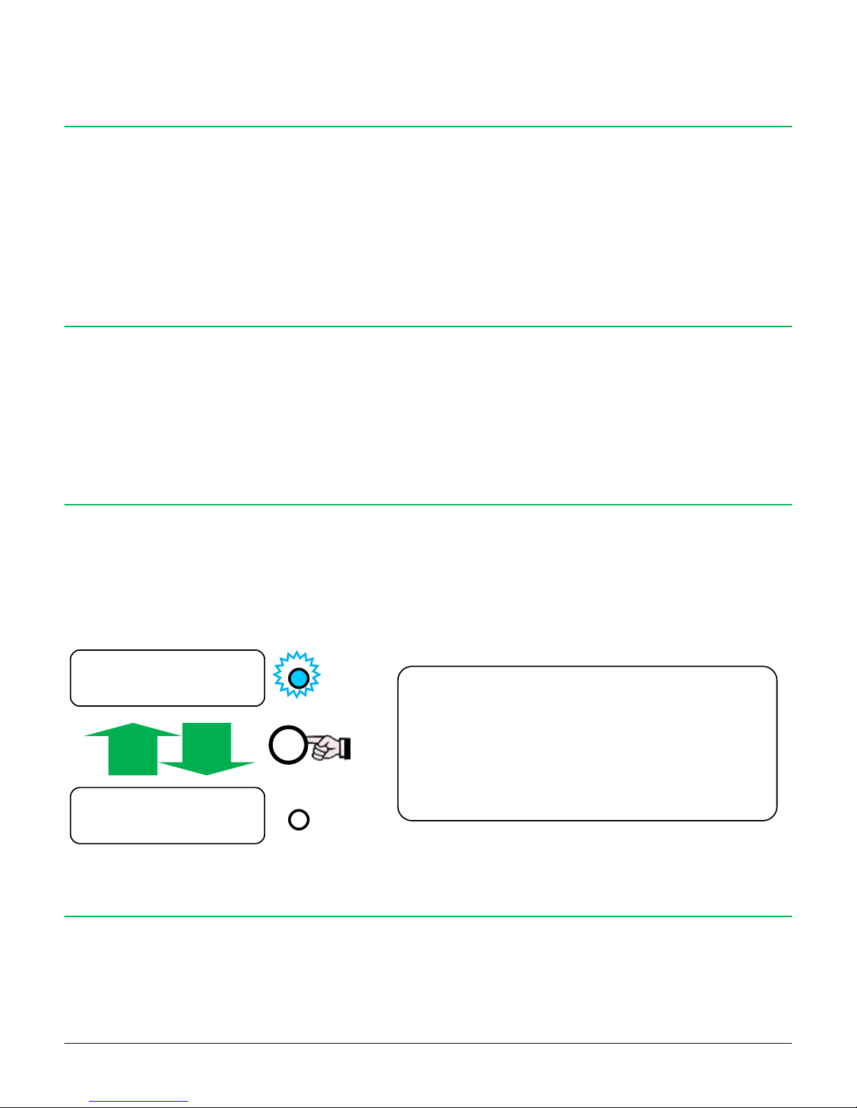
6.3. ALERT
The control panel can emit two different types of sound alert when the (selected) zones are violated at system disarmed:
Bell: this type of Alert is a simple “ding dong” sound type
Voice (only from wireless radio zones 1 ÷ 30): the panel (if the optional accessory AMP is installed) alerts a wireless zone violation with
a combined voice message to the zone in alarm (the voice alert identifies the violated zone).
The user can enable and disable the Alert function (globally, see next description) and select which zones must trigger the Alert (User Menu).
6.4. PRE-ALARM TIME
The control panel can provide a Pre-Alarm signal (low intensity sound before the proper alarm) only on partial sensors (perimeter sensors) only
when the control panel is armed in Partial mode (it is to say when the user generally is inside the house).
In this way the user will be warned of an intrusion attempt on the perimeter without alarming outright the high powered siren. In case the
control panel is not disarmed within the pre-alarm time (adjustable by the installer) the control panel will activate the high powered siren.
Press briefly the “X” button: the “ALERT” function is
enabled/disabled on control panel (bell and voice, on
each zone with Alert option enabled)
BLUE LED ON = “ALERT” enabled
BLUE LED OFF = “ALERT” disabled
ALERT
ALERT
10:20 01/03/10 =
Disinserito O
X
12:30 06/02/15 ▄
Disarmed ▄ O
12:30 06/02/15 ▄
Disarmed ▄ O
Page 12
12
6.5. PANEL TEST
It allows testing each wireless/wired sensor and the activators. With the control panel disarmed and pressing for at least 3 seconds the “#”
button you can enter the Panel Test mode.
It is possible to perform a series of tests on wired/wireless sensors and on activators: for each signal/transmission received, the control panel
will emit a “beep” (different tones depending on the type of the device activated) and it will show on the display the name of the device.
To exit keep pressed for few seconds the “#” button or wait about 2 minutes without transmitting.
6.6. TAMPER
The control panel can manage the signals of Self-protection TAMPER of the wired peripheral devices (sensors, sirens, diallers, etc) and of the
control panel open cover.
It is possible to choose to enable or disable this protection through the J.TMP.LN (external devices tamper) and J.TMP.BOX (control panel
internal tamper).
When this function is enabled, the Tamper control will ALWAYS BE ACTIVATED (with the control panel armed or disarmed).
In case of tampering, the control panel will generate immediately alarm. Disarming the system, the display will show the occurred alarm showing
“TAMPER/WIRE”.
IF YOU WANT TO HAVE CONTROL ON EXTERNAL TAMPER IT IS COMPULSORY TO OPEN THE JUMPER J.TMP.LN IN
ORDER TO AVOID CONTROL PANEL MALFUNCTIONING.
6.7. LOW BATTERY
The control panel shows on the LCD display whenever the control panel battery of a sensor goes under a certain level of charge, to warn the
user that the battery is discharging.
The red LED L1 lights on for both control panel and keyboards (if present) showing status signal.
IF SET UP, CONTROL PANEL AND/OR SENSORS LOW BATTERY SIGNALS ARE SENT (THE LAST ONES ONLY WITH
DISARMED SYSTEM).
6.8. TECHNOLOGIC ZONES
This type of zone is 24h/24 active regardless of control panel arming status: useful for technologic sensors such as smoke sensors, flood sensors,
etc… The AUX1, AUX2 and AUX3 relay outputs can be associated to “Technologic” event to trigger it when this type of zone detects.
6.9. OPENED DOORS ALERT
The control panel can give also to the user information about eventual Open Doors when trying to arm.
To receive this type of information, the installer must enable the “Door Control” function (see chapter 3 “USE OF THE PANEL” for further details).
Disabled function
Disarmed > The control panel will never alert the presence of open contacts.
Armed (Total, Partial or External) > During the arming there will be NO alert and possible open contacts will be automatically excluded.
With armed system, when the contact is closed, the detection will be activated on it; at this point a re-opening of the contact will generate
alarm.
Page 13
13
Function enabled
Disarmed > The control panel will signal the Open Doors with a blinking of the yellow LED L2 if one or more contacts are open.
Armed (Total, Partial or External) > During the arming the control panel will emit an acoustic signal (“beep”) for about 10 seconds during
which it is necessary to:
o Close open contacts within the signalling time.
o Suspend the arming (with remote control or other activator).
The control panel will show the “Open Doors” warning: press the “#” button to see the list of the contacts still open. If these are closed
during this phase the control panel continues the arming, otherwise it goes back to disarmed status.
o Force the arming (with remote control or keyboard). The system is armed and excludes the open areas.
o In case of no intervention: at the end of the signalling time the system is disarmed without excluding the open areas: the alarm starts.
6.10. ANTI-BLINDING
Radio signals used by the sensor to “talk” with the control panel and communicate an alarm can be disturbed.
These troubles, named “masking”, can stop the effect of waves produced by the security system and they can become invisible to the control
panel.
The CE 60-8 is provided with a function that allows to generate alarm as soon as the system (when armed) recognizes a potential “blinding”.
IN CASE OF MASKING THE ALARM STARTS (INTERNAL SIREN AND EXTERNAL, IF PRESENT – CAN BE DISABLED).
VOICE CALLS AND MASKING WARNINGS SMS ARE SENT.
THIS FUNCTION CAN BE ENABLED/DISABLED BY THE INSTALLER.
6.11. CONTACTID
The control panel can send coded events to a surveillance system through GPRS network (mobile network technology) or through GSM messages
(SMS, equipped with a VIGILANT receiving module).
In this way, in case of intrusion or failure in your home, the surveillance system will receive the event and react quickly.
Ask your installer for more details.
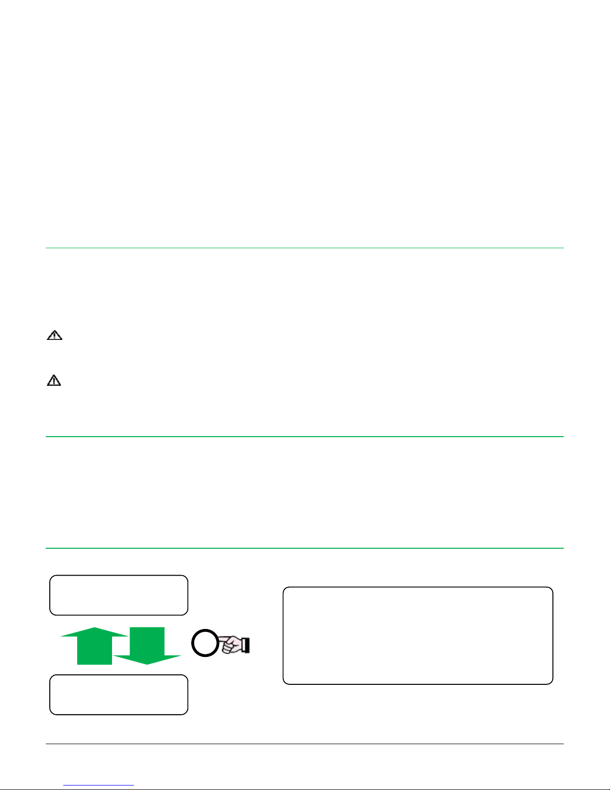
6.12. INCLUDE/EXCLUDE EXTERNAL ZONES
To exclude or include External zones (E) from Total and Partial arming:
After 1 minute from the disarming, pressing for a long
time the “X” button, you can include or exclude External
zones (E) when armed in Total or Partial.
On the display:
“O” = Outdoor sensors (E) included
“X” = Outdoor sensors (E) excluded
long
X
12:30 06/02/15 ▄
Disarmed ▄ O
12:30 06/02/15 ▄
Disarmed ▄ X
Page 14
14
6.13. EXTERNAL ZONES ALARM/RING
FUNCTION VALID ONLY FOR EXTERNAL ZONES
This function allows associating a low intensity beep to the outdoor sensors instead of the normal alarm.
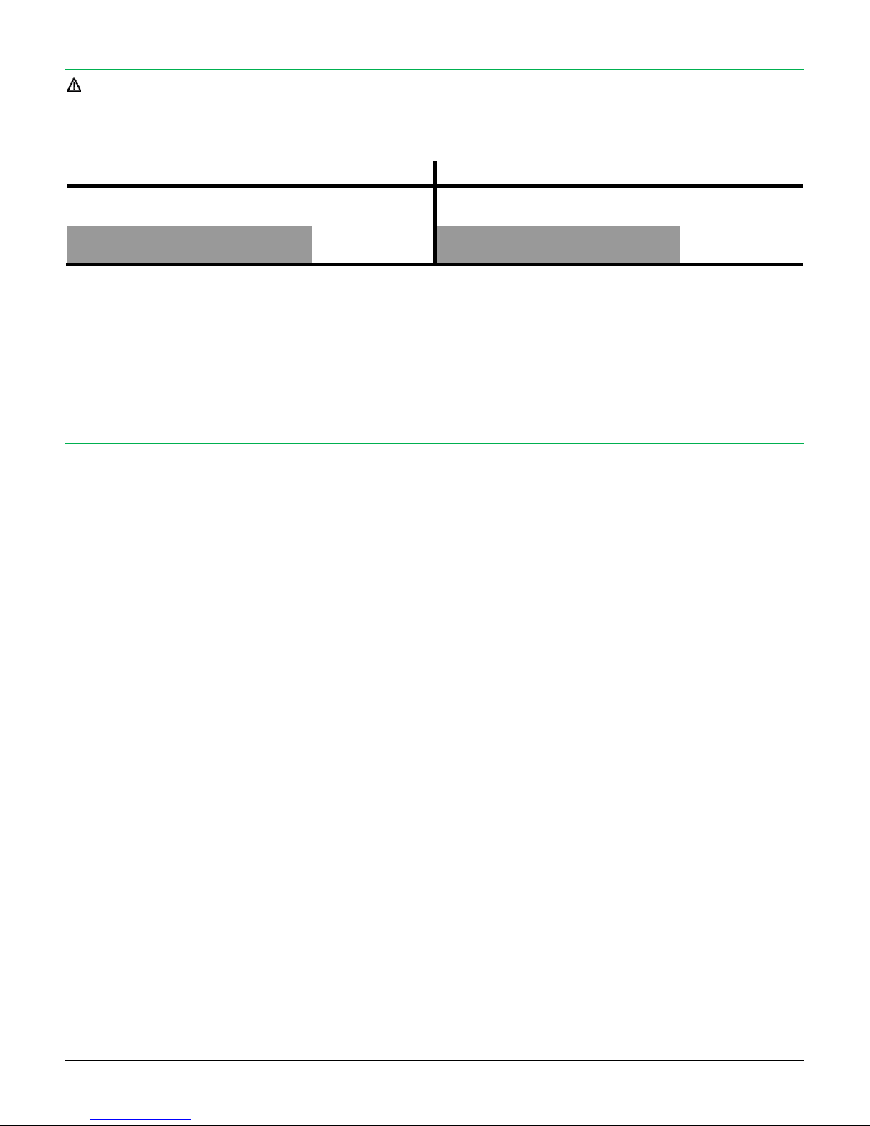
See the following table for the different control panel response depending on the enabled or disabled function:
EXTERNAL ZONES RING ON
EXTERNAL ZONES RING OFF
TOTAL ZONES
PARTIAL ZONES
EXTERNAL ZONES
TOTAL ZONES
PARTIAL ZONES
EXTERNAL ZONES
Beep
(60 seconds)
Alarm
(3 minutes)
1. EXTERNAL RING = ON > Useful when you want to program as External the zones positioned strategically in the outdoor area of the
principal area to protect, that during the detection do not generate alarm but activate a low intensity "warning" beep (60 seconds).
2. EXTERNAL RING = OFF > Used when you want that the programmed External zones always generate alarm.
6.14. GSM ANTI-JAMMING
The control panel is able to detect if the module GSM is not able to establish a correct communication with the network operator due to a
jamming of the GSM signal.
The relay outputs can be combined to this event and activated in case of jamming - by which it is possible to activate an alternative communication
system (example: PSTN module, wireless bridge…) and receive a warning.
Note: in case of no network (for example: the provide is not available at the moment, the control panel is installed where the GSM signal is
weak….) the anti-jamming does not indicate jamming, the dedicated output remains at rest.
Page 15
15
7. TEMPERATURE CONTROL FUNCTION
THE THERMOSTAT FUNCTION CAN WORK ONLY IF THE TEMPERATURE PROBE (OPTIONAL) IS BEEN INSTALLED.
THE THERMOSTAT FUNCTION CAN WORK ONLY IF A RELAY OUTPUT IS PROGRAMMED AS “TEMPERATURE”.
THE CONTROL PANEL MUST BE PROPERLY CONNECTED TO THE HEATING SYSTEM THROUGH THE RELAY OUTPUT.
The control panel switches on the relay output depending on the difference of temperature between the ambient temperature (measured by
the probe) and the desired temperature (programmed by SMS).
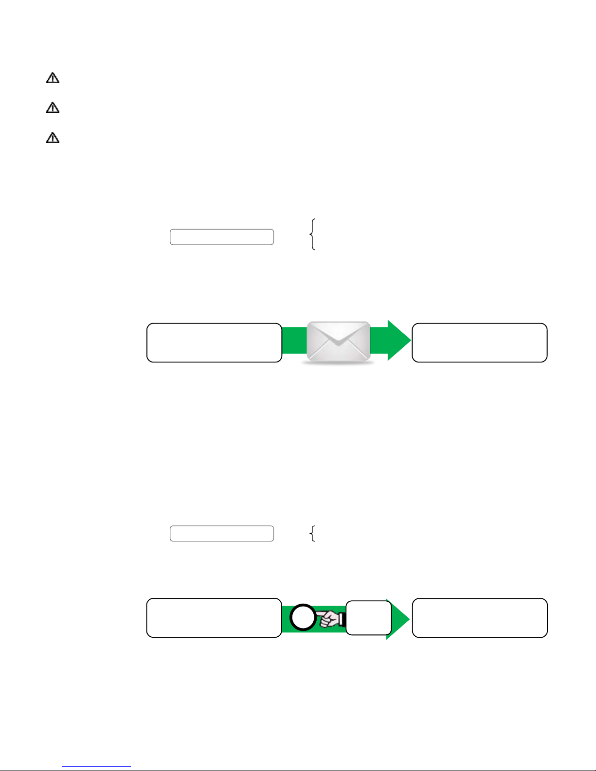
Activation > Send * an SMS with the following text:
* See paragraph 11, “GSM: FUNCTIONS AND PANEL MANAGEMENT” for details about SMS sending.
Response > The thermoregulation is activated for 24 hours from the receiving of the activation SMS.
The control panel activates the relay output programmed every time the ambient temperature goes under the temperature
TT desired.
Only the first time that the temperature TT desired is reached, the control panel sends a confirmation SMS.
If, at the end of 24 hours, the temperature desired is not reached, the control panel sends a SMS informing about the
ambient current temperature.
Deactivation > 1. At the end of the 24 hours the function is automatically deactivated.
2. Send* an SMS with the following text:
3. To exit at any time from the thermoregulation (with disarmed system) press the “#” button for at least 3 seconds (no
SMS):
xxxx Remote Code
TT Desired temperature
xxxx#temp onTT
Press
long
#
xxxx Remote Code
xxxx#temp off
12:30 06/02/16 ▄
Disarmed ▄ X
12:30 06/02/16 ▄
Heating=28° ▄ X
12:30 06/02/16 ▄
Heating=28° ▄ X
12:30 06/02/16 ▄
Disarmed ▄ X
Page 16
16
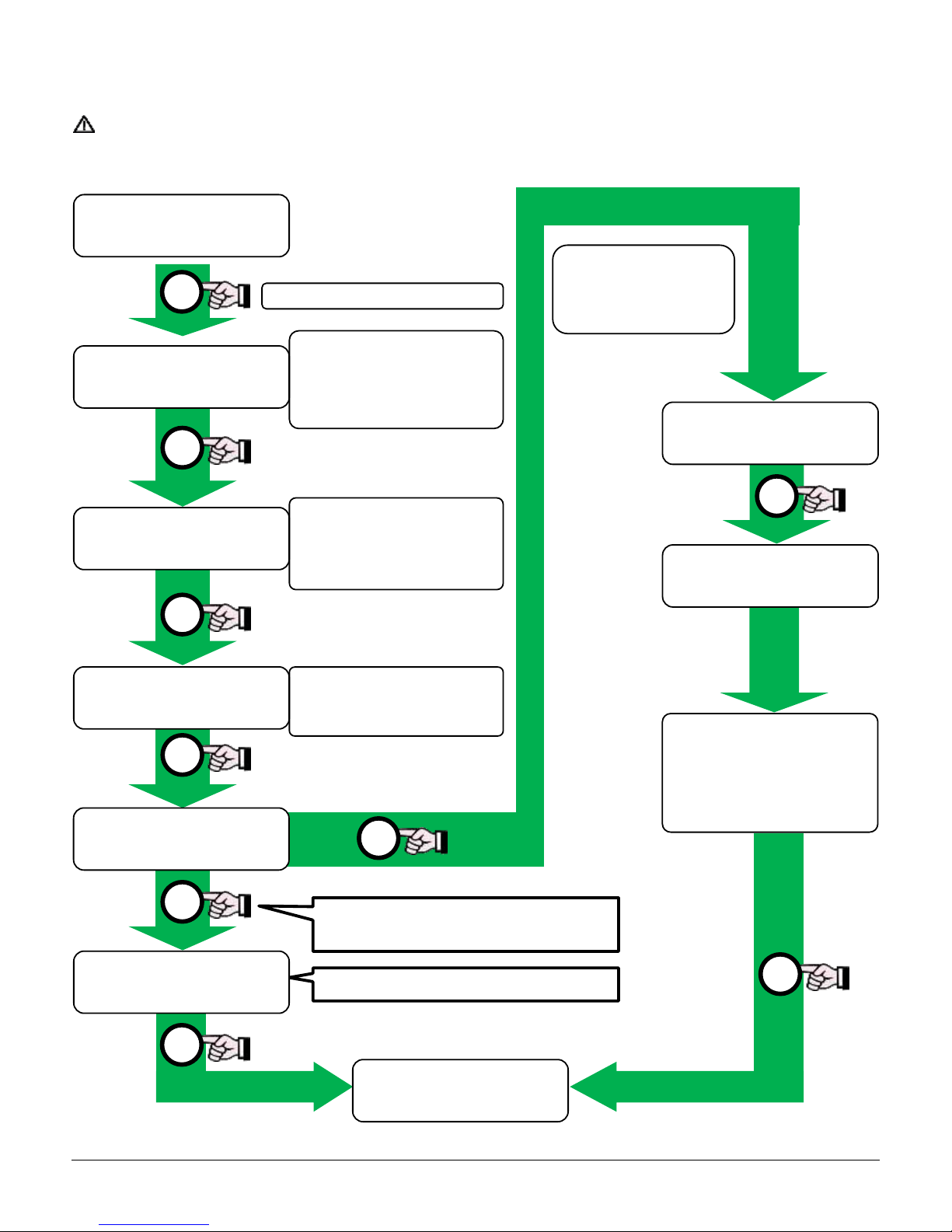
8. MODEM MENU / CREDIT REQUEST
SOME OPTIONS OF THIS MENU ARE AVAILABLE ACCORDING WITH INSTALLATION AND CONFIGURATION OF THE
MODEM AND PANEL.
PRESS LONG
Visualize the modem
status. In case of problems
the display shows “Modem
NON OK”
If the modem is connected
to the GSM network, the
display shows the provider
name.
Visualize a graphic bar
showing the GSM signal
level.
Select “YES” to ask for
the residual credit on
SIM (only rechargeable
type)
Wait the provide answer for
the available credit request
(max 3 minutes).
The answer is shown on the
second line of the display.
Not visualized if the SIM card is set as
“contract SIM”
O
#
#
#
#
O
#
#
See paragrph “EVENTS LOG”
#
12:30 06/02/16 ▄
Disarmed ▄ O
Event log
Credit request
No
Modem signal
▄ ▄ ▄ ▄ ▄ _ _ _
Provider
I TIM
Modem Ready
Modem Result OK!
12:30 06/02/16 ▄
Disarmed ▄ O
Credit request
Yes
Credit request
...............
Page 17
17
9. USER MENU
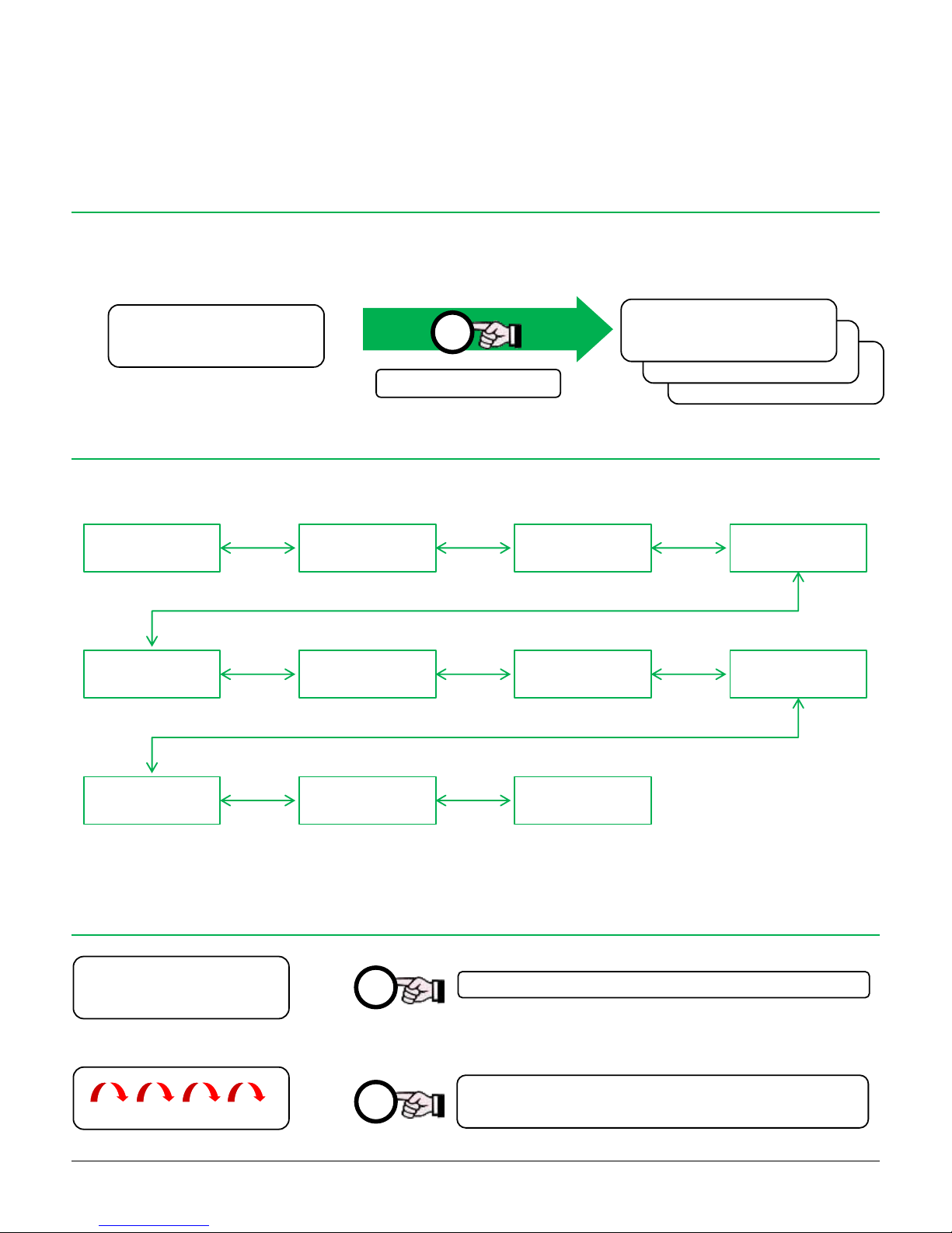
The control panel allows the user to set some functions (after the installation), operating directly on the keys collocated on the frontal panel,
with no need of installer intervention.
9.1. ENTER THE USER MENU
To enter in User Menu:
1. Disarm the panel (even if already disarmed)
2. Within 2 minutes, press and hold the “X” button until the User Menu appears
9.2. USER MENU ITEMS
9.3. DATE AND TIME
Date and Time Remote Code Delete Activators Alert
Exclusion
Program
Voice Messages
Program
Beep at Arming External Alarm
Siren Test
Wireless
Saturation
Exit
Programming
10:20 06/02/16
Press long
Each pressure of the button, select: HOURS, MINUTES,
DAY, MONTH, YEAR
Each press of the button the value increase of one unit
X
O
X
12:30 06/02/16 ▄
Disarmed ▄ X
Date and Time
10:20 06/02/16
Progr. Alert D
Zona Filo 01 P
Cod. Combinatore
0000
Date and Time
10:20 06/02/16
To go to next item: press short the
“#” button
To go to previous menu: press long
the “#” button
Page 18
18
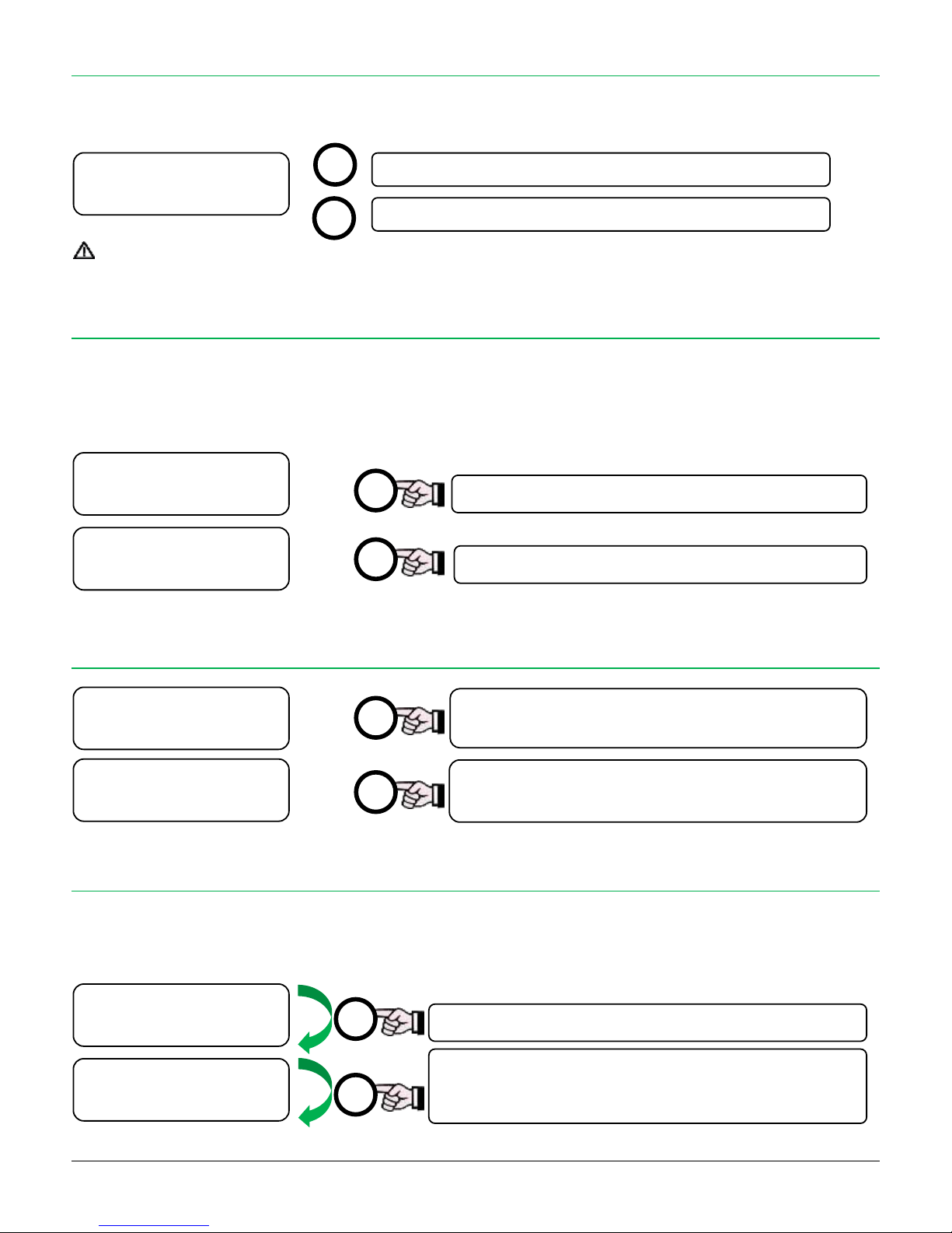
9.4. REMOTE CODE
This is the 4 digit security code for access to dialler function: it is required for SMS commands and Voice Menu.
Factory value: “0000” (four zeros). The panel ignores all commands with wrong Remote Code.
FOR BEST SECURITY, ALWAYS CHANGE THE DEFAULT REMOTE CODE WITH A CUTOMIZED ONE
9.5. DELETE ACTIVATOR
This option allows to visualize and delete the activators stored in control panel. Useful in case of loss of an activator.
Press the “O” button to go to next activator.
To delete the activator visualized, wait for the “X” symbol (memory occupied) and press long the “X” button. When the “O” symbol appears
instead of the “X”, the activator is deleted.
9.6. ALERT PROGRAM
9.7. TEMPORARY EXCLUSION PROGRAM
The temporary exclusion allows to disable one or more zones only in next arming, then after disarming they will return active. This function is
useful for example to arm the system in Total mode and bypass the sensors in a zone, in which will be possible to stay without generate alarm,
with all the other zones active.
Remote Code
0000
Each press moves to next zone (Wired Zones and Radio
Zones)
Each press vhanges the status:
D = ALERT disabled A = ALERT enabled
Cancellazione X
Inseritore 01
Each press go to next activator
Press long to delete the activator selected
O
X
O
X
Each press moves to next zone (Wired/radio Zones)
Press to exclude the slected zone. The “X” symbol appears
to confirm the exclusion.
Press again to include the zone.
X
O
Progr.Exclus. X
Wired Zone 02 P
Progr.Exclus.
Wired Zone 01
Progr. Alert A
Wired Zone 02 P
Progr. Alert D
Wired Zone 01
Delete 0
Activator 04
Delete X
Activator 01
Each press increases the value
Each pressure changes the digit
O
X
Page 19
19
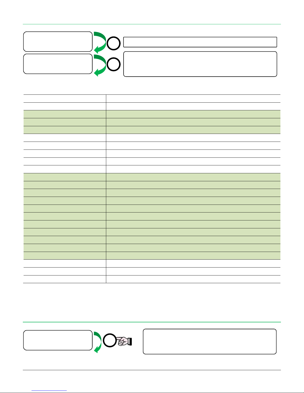
Short press: play the selected message
Long press: record message (max 12 seconds)
To stop the recording press short the “#” button
9.8. VOICE MESSAGES PROGRAM
The next table contains the voice messages event list with the default text (for customization of the messages):
Voice messagee
Deafult text
WARNING: each message can last mex 12 seconds
Alarm
“Theft in progress”
Silent Alarm
“Silent alarm”
Panic
“Panic message”
Disarmed with coercion
“Disarmed with coercion”
Disarmed
“Disarmed”
Total arming
“Total arming”
Partizl arming
“Partial arming”
External arming
“Outdoor arming”
Tech message 01
“Digit Personal Code followed by ash key (#)”
Tech message 02
“Wrong Code”
Tech message 03
“Wrong Command”
Tech message 04
“For arming status press zero (0)”
Tech message 05
“To disarm press one (1)”
Tech message 06
“To arm totally press two (2)”
Tech message 07
“To arm partially press three (3)”
Tech message 08
“For outdoor arming press four (4)”
Tech message 09
“For environmental listening press eight (8)”
Tech message 10
“To credit SIM request press nine (9)”
Tech message 11
“Credit request in progress. Wait for SMS”
Message Radio Zone 01
“Attention, detection on radio zone 1”
… … Message Radio Zone 30
“Attention, detection on radio zone 30”
9.9. ARM/DISARM BEEP
Each press moves to next message
“Beep” at arming /disarming
Press to enable (ON) or disable (OFF) the acoustic
“beep” at arming and disarming
X
O
X
Beep Arm/Disarm
ON
Voice messages
Panic
Voice messages
Alarm
Page 20
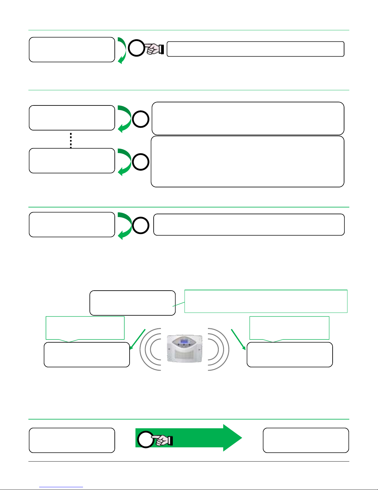
20
9.10. EXTERNAL ZONES BEEP/ALARM
9.11. SIREN TEST
Function to verify the communication between control panel and radio siren.
9.12. RADIO SATURATION
The control panel can analyse the radio environmental “quality”.
In fact – in the installation environment there may be one or more radio emitting sources (temporary and/or continued, intentional or not) with
the same operating frequency of the panel. The radio signals emitted can interfere with the communication system of the control panel, causing
“blinding”. The test shows on display (during all the test) the digital counting (Cnt) and the radio power level (Rx):
The control panel continues its normal working during the test: it is possible to arm and disarm. The test stays active and stops automatically
after 2 hours.
The test generates a special acoustic alert for 30 seconds in case of one of the two types of “blinding”.
9.13. EXIT PROGRAMMING
Press to activate/deactivate the Saturation test: this test verifies the radio
environment.
Press “X” to exit
from MENU
The panel generates an alarm: the siren receives the alarm code and after 3 seconds
the disarm code.
If the communication works correctly, the siren will sounds for 3 seconds.
The control panel ask for tamper code to the siren.
The siren replays with a long flash and sends its temper code.
If the code is already learnt, the control panel emits some “beep” to confirm the
siren is correctly learned.
If the code is not stored, no “beep” from control panel: check the siren pairing.
X
O
Press to enable or disable the function (see paragraph 6.13)
X
X
X
Exit menu
12:30 06/02/16 ▄
Disarmed ▄ O
Radio Saturation
Yes
Siren Test
Siren Test
External Alarm
No
ALARM if Cnt reaches the
value 5500 within 60 s
ALARM if Rx exceeds the
value 170 for more than 20 s
Cnt=00255 Rx= 57
Disarmed ▄ O
Radio Blinding
Digital
Radio Blinding
Analogic
Radio blinding level: 0 = OFF,
1 = HIGH ÷ 5 = VERY LOW (change with “#” button)
Page 21
21
10. VOICE MENU
The voice menu uses the DTMF tones technology.
The correct working of this technology depends on the DTMF quality at the control panel and this is affected
by: GSM signal level at the panel, GSM signal level at mobile phone, DTMF tones quality generated by the mobile
phone, noise on the GSM network.
Due to these factors it is NOT possible to always ensure the proper working of tone selection in vocal menu.
Alternatively, to manage the control panel from remote, the user can use the command SMS set (see paragraph
“GSM: FUNCTIONS AND PANEL MANAGEMENT”).
The relay outputs must not be set as RING, otherwise the call to control panel would be used to activate the
relay and the vocal menu would be deactivated!
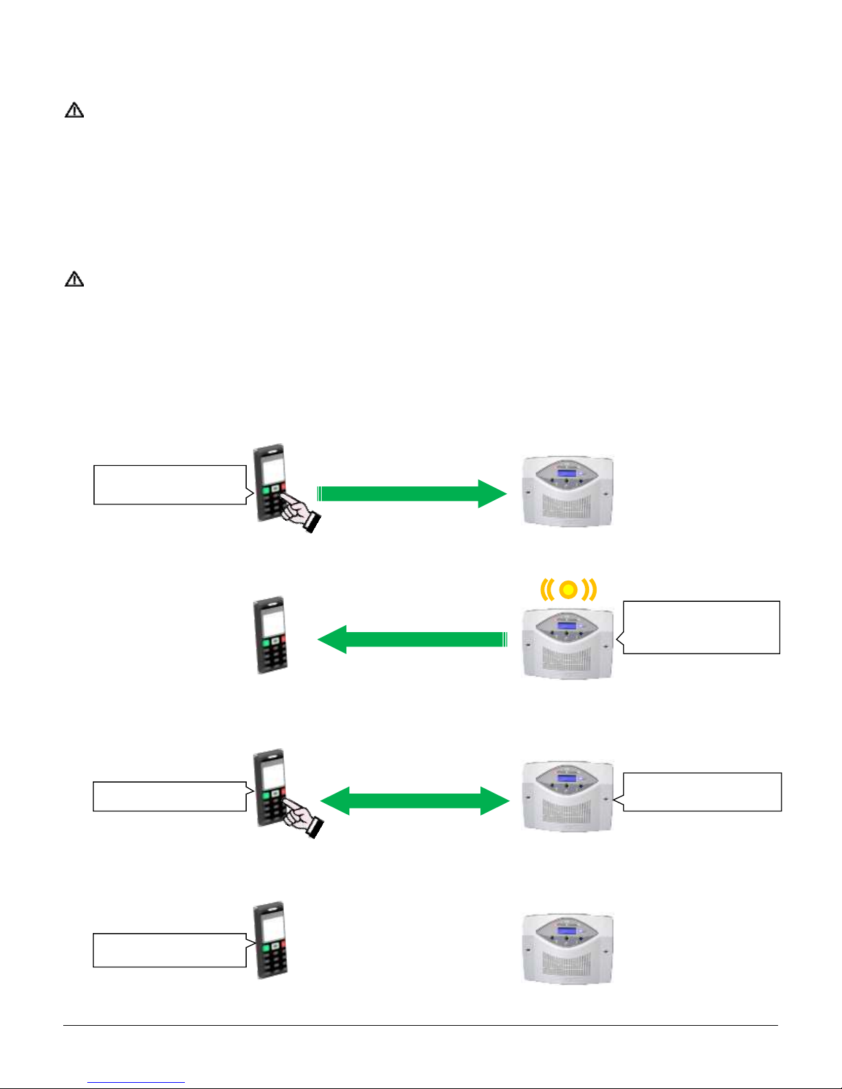
It is possible to call the SIM telephone number in the control panel in order to use the vocal menu: a voice proposes an action, that it is executed
if the corresponding button is pressed on the telephone keyboard
1. Dial the telephone number of the SIM in the control panel:
2. Wait for the answer of the panel:
3. Follow the voice instructions of the menu, press the keys corresponding to the desired option:
4. At the end of the operation, just close the call.
Call the control panel
The panel answers.
The yellow LED blinks
Message from panel
Desired option key
Close the call
Page 22
22
10.1. VOICE MENU OPTIONS
Digit the Remote Code followed by “#”
Corresponding voice message > Technical Message 01
To enter the voice menu, it is necessary to digit on the keyboard the Remote Code (see the chapter REMOTE CODE) followed by “#”. After
that, the control panel starts the description of the available options and of the related buttons.
Example: if the SMS PIN Code chosen by the user is 1234, he will have to digit on the telephone:
1234#
It is possible to select more than one option during the same call.
To do this: after selected an option, press the “#” key to return menu. Then select a new option.
In case of digit error, the control panel alerts the user with a “wrong code” voice message” (Tech Message 02).
To return to menu, press “#” key.
The control panel allows listening the voice menu for a maximum time of 1 minute without selecting an option,
then it ends the calling. This time restarts from the last command given.
Choose therefore the desired option within this time.
SYSTEM (ARMING) STATUS (KEY 0)
Corresponding voice message> Technical message 04
To know the arming status of the installation (Total, Partial, External or Disarmed).
It follows the vocal indication of the current control panel status.
Example: the system is TOTAL armed. The user digit “0” (zero) will hear:
“TOTAL armed”
DISARM (KEY 1)
Corresponding voice message > Technical Message 05
To disarm the system from remote.
It follows the vocal indication once the arming is executed.
Esempio: l’impianto è inserito TOTALE. L’utente premendo “1” disinserisce l’impianto e sentirà:
“Disarmed”
TOTAL ARM (KEY 2)
Corresponding voice message > Technical message 06
To arm the system in TOTAL mode from remote.
It follows the vocal indication once the arming is executed.
Example: the system is disarmed. Digit “2” (two) the system is armed in TOTAL mode and you will hear:
“TOTAL armed”
0
1
2
Page 23

23
PARTIAL ARM (KEY 3)
Corresponding voice message > Technical message 07
To arm the system in PARTIAL mode from remote.
It follows the vocal indication once the arming is executed.
Example: the system is disarmed. Digit “3” (three) the system is armed in PARTIAL mode and you will hear:
“PARTIAL armed”
EXTERNAL ARM (KEY 4)
Corresponding voice message > Technical message 08
To arm the system in EXTERNAL mode from remote.
It follows the vocal indication once the arming is executed.
Example: the system is disarmed. Digit “4” (four) the system is armed in EXTERNAL mode and you will hear:
“EXTERNAL armed”
ENVIRONMENT LISTEN (KEY 8)
Corresponding voice message > Technical message 09
To start the listening – through the on-board microphone of the control panel – of what happens in the environment in which it is
installed. After pressing “8” (eight) the environmental listening starts.
The listening has a maximum duration of 2 minutes, then the control panel closes the call.
Example: digit “8” (eight), the on-board microphone is activated and you will hear the environmental sounds.
SIM CREDIT REQUEST (KEY 9)
Corresponding voice message > Technical message 09
To start the SIM (of the control panel) residual credit request.
After digit “9” (nine) the control panel advises that the request is been sent (Tech message 11). The user can close the call.
The control panel (if it is correctly programmed) asks the residual credit to the operator. When it will receive the residual credit SMS it
will be sent to the number that calls the panel to make the request.
The user will receive the residual credit SMS.
Example: the control panel has on-board a SIM of the GREEN operator (programmed with the GREEN number 12345).
The user digits “9” (nine) the control panel calls the number 12345, it receives the SMS of residual credit and it will forward it to the
user number the user receives the SMS of residual credit at its own number.
3
4
8
9
Page 24

24
11. GSM: FUNCTIONS AND PANEL MANAGEMENT
The integrated GSM dialler is able to send to the user warnings about different occurred events in the control panel (alarms, arming and
exclusions, SIM of control panel status, etc.) providing the user with a practical method of control of the system and allowing a fast and
appropriate intervention.
The CE 60-8 GSM control panel can be managed by remote through the sending of simple SMS messages.
The control panel can store up to 8 telephone numbers to which it sends advice through calling and/or SMS messages.
11.1. FACTORY SETTINGS
The positions of the numbers from 1 to 8 are planned by factory with a standard association of the warnings that must be sent.
These settings can be modified with a programming software (only for installers).
Store the telephone numbers so to obtain the type of messages that each telephone number wants to receive following this plan:
The positions 1 ÷ 4 have the same associations and they are enabled to receive alarm and technical vocal calls and SMS text messages.
Program in these positions ONLY MOBILE PHONE NUMBERS.
The positions 5 ÷ 8 are associated only to the theft alarm vocal call, and they are valid for any telephone number type (fixed, emergency
and mobile).
N°
SMS
SMS
SMS
SMS
SMS SMS
SMS
VOICE CALL
Arming Status
Alarm
Panic
Silent Alarm
Supervision
Power Status
Battery
Status
Alarm
Panic
Silent Alarm
1 • • • • • • • • 2
• • • • • • •
3 • • • • • • •
4 • • • • • • •
5 Only alarm 6
Only alarm
7 Only alarm
8 Only alarm
Factory settings of the telephone numbers
Voice
Voice call: warning function for alarm, panic or tele-alarm through voice calls.
SMS
Alarm: “alarm in progress” warning.
Panic: warning for activation of the special PANIC remote control.
Arming status: at each arming/disarming status change an information SMS will be sent.
Silent Alarm: warning for activation of the special SILENT ALARM remote control.
Supervision: correct functioning information (monthly) of the internal dialler.
Power status:
o Power line: notification of absence/reestablishment of the power line.
o Battery: low battery status signalling.
Page 25
25
11.2. CONTROL PANEL ACTIONS/REACTIONS
In case of alarm, the control panel firstly sends all the SMS and then it starts to call the first number enabled for the calling option, for the
number of times programmed. Then – in sequence – it calls the second number enabled for the number of times planned … and so on until
the last number.
Hence, if you want that the control panel calls quickly all the numbers:
Program a number of calls equal to one (adjustable by the installer)
or
Who receive the call, after listening the message, must block his call with 0# (see “BlocK ONGOING CALLS”, paragraph 12).
The dialler will proceed to the next number in memory..
If wireless bidirectional sirens and keyboards are not used, it is possible – by leaving empty the first position of the activators (adjustable by the
installer) – to disable the wireless communication from the control panel: therefore it will be faster to call and send the alarm SMS.
Note about the “Single SMS” function (adjustable by the installer)
The control panel sends as many SMS as detections by the sensors, in order to know the past events and what it is happening during alarm.
If “Single SMS” is enabled, for each alarm cycle, it will be sent only one SMS to each number enabled, warning is related only to the first sensor
that starts the alarm; afterwards the control panel makes the calls following the procedure described above.
IN CASE OF ALARM > FIRSTLY ALL THE SMS MESSAGES WILL BE SENT, THEN THE VOICE CALLS WILL START
THE CONTROL PANEL PROVIDED WITH ACTIVE SIM IS ALWAYS READY TO RECEIVE COMMANDS VIA SMS.
THOSE MESSAGES, TO BE ACCEPTED BY THE CONTROL PANEL, MUST CONTAIN THE REMOTE CODE ADJUSTABLE BY
THE USER. THIS GUARANTEES THE SECURITY AGAINST UNAUTHORIZED ACCESS.
THE FACTORY REMOTE CODE IS::
0 0 0 0 (FOUR ZEROS)
AND IT IS ADJUSTABLE BY THE USER/INSTALLER.
FOR SECURITY REASONS IT IS RECOMMENDED TO ALWAYS MODIFY THE SMS PIN CODE WITH A CUSTOMIZED ONE.
THE SMS COMMANDS CAN CONTAIN SPACES AND MUST BE CONSIDERED PART OF THE SYNTAX, FOR THIS REASON
THEY MUST BE INSERTED EXACTLY AS INDICATED.
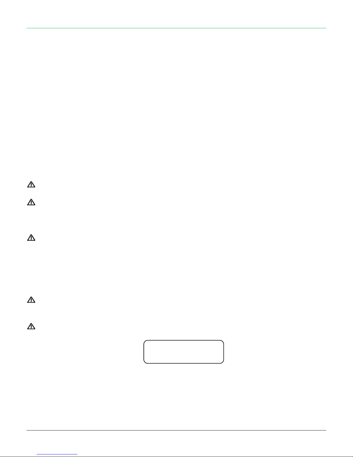
DISPLAY MESSAGE DURING THE SENDING OF ACTIVATION, ALARM AND PROGRAMMING SMS
SENDING EVENT
Page 26
26
11.3. ADD TELEPHONE NUMBERS
To program the telephone numbers to which the GSM dialler will send the warnings, do as follows.
The panel telephone memory for GSM dialler is empty (if not programmed by user or installer).
The REMOTE CODE by factory settings is “0000” (four zeros), so the control panel will accept the commands from any mobile phone number that
sends a command with code “0000” (four zeros).
Send from a mobile phone to the SIM card number inserted in the control panel a SMS message for each number to be stored.
The text of the SMS message must be written as follows:
xxxx#num n qqqqqqqqqqqq
xxxx
Remote Code
n
Memory position: from 1 to 8
qqqqqqqqq
Number of telephone to be stored preceded by the international country code without “00” or “+” (e.g.:
for UK is 44)
Example: Mr Rossi wants to program his mobile number (333.44.44.444) in his new control panel CE 60-8 GSM in order to receive the
messages in case of theft or other events and manage the system at distance.
Then it will send to the telephone number of his control panel the following SMS:
0000#num 3 393334444444
The Remote Code of the control panel is “0000” (factory).
The mobile phone number 333.44.44.444 (the digits 44 before the number are been inserted for the calls of an U.K. number)
will be recorded in the memory position n. 3.
From this moment forward Mr. Rossi can receive the vocal calls and the SMS from panel.
It is possible to program the dialler to make calls also towards landline telephone numbers.
THE MEMORY POSITIONS FROM 2 TO 8 CAN CONTAIN BOTH GSM AND LANDLINE NUMBERS.
THE MEMORY POSITION NUMBER 1 IS SPECIAL AND IT CAN CONTAIN ONLY A GSM NUMBER (THE SIM EXPIRY IS
SENT JUST TO THIS NUMBER).
Example: Mr. Red wants to receive a call from the control panel in case of alarm on landline nr. 011.77.55.333 (it could be the number
of the second house or of a relative); it will program (like in the former example, by SMS) in the control panel also this
number:
0000#num 5 390117755333
11.4. DELETE TELEPHONE NUMBERS
To delete a telephone number in memory:
xxxx#del n
Delete the telephone number in memory “n”
Example: in memory, at position 5, it is present the telephone number 011.77.55.333. Mr. Red wants to cancel this number, therefore he
sends the following SMS (the Remote Code is 0000):
0000#del 5
Page 27
27
11.5. PANEL MANAGEMENT SMS COMMANDS
Follows the full list of commands available on the control panel by SMS.
All the commands must start with the Remote Code of 4 digits (“xxxx”): the factory value is “0000” (four zeros) but it is recommended to program
a personal one once finished the installation.
Command
Function
xxxx#out Nonttt
Activates the relay output AUX-N for ttt seconds (from 001 to 999)
xxxx#out Non
Activates the relay output AUX-N
xxxx#out Noff
Deactivates the relay output AUX-N
xxxx#temp NonTT
Activates the relay output AUX-N for heating control at TT grades, for 24 hours
xxxx#temp Noff
Deactivates the relay output AUX-N from heating control
xxxx#instot
Total arming
The control panel confirm the arming with
an SMS, with indication of eventual
opened doors
xxxx#inspar
Partial arming
xxxx#insext
External arming
xxxx#disins
Disarming
xxxx#stop
Stop calls: stop all ongoing calls
xxxx#status
Returns the arming status of the control panel and the state of the outputs
xxxx#signal
Returns the GSM signal level
xxxx#listen
Environment listen (up to 5 minutes)
xxxx#config
Returns the actual telephone numbers settings
xxxx#riccre
Ask for available credit on SIM: the panel returns the residual credit SMS
xxxx#num n yyyyyyyyy
Add the telephone number “yyyyyyyyy” in memory position “n”
xxxx#del n
Delete the telephone number in memory position “n”
xxxx#scad DDD
Set the number of days DDD before send the “SIM expiring” memo
xxxx#extincl
Includes the External zones (E) when arming in Total and Partial
xxxx#extescl
Excludes the External zones (E) when arming in Total and Partial
xxxx#abilrem
Enable the remote communication (control panel program via GPRS)
xxxx#fineabilrem
Disable the remote communication
xxxx#eiv D
“In life” alert time for the GSM modem. The D value set the time:
D = 0 12 hours
D = 1 24 hours
D = 2 48 hours
D = 3 72 hours
D = 4 1 week
D = 5 1 month
Page 28
28
11.6. EMERGENCY NUMBERS
It is possible to program the public emergency numbers (example: 911) in the same way as the other telephone numbers, WITHOUT the
international country code:
Example: Mr. Rossi wants to program the Policy number:
0000#num 5 113
11.7. ASK FOR SIM CREDIT
In order to know the residual SIM credit in the control panel, set up properly the SIM type in the control panel and type the following
command:
xxxx#riccre
It starts the SIM credit request to the telephone operator: the control panel answers with a residual credit SMS.
In case of connection failure the control panel sends “no reply from the operator, try later”.
The control panel asks the residual credit to the operator and sends the received information to the number which sent the request.
11.8. SET THE ALERT FOR SIM EXPIRING
Set the number of days after which the control panel will send an SMS alert for the SIM expiration. If the number of days is set to "0"(zero), this
service is disabled.
xxxx#scad yyy
Set a reminder for SIM expiration between yyy days
THE NOTICE OF SIM EXPIRATION WILL BE SENT FROM THE CONTROL PANEL ONCE ONLY (AT THE END OF TIME SET)
AND ONLY TO THE FIRST NUMBER STORED IN THE INTERNAL DIALLER
ONCE IT EXPIRES, IT IS NOT RESTORED AUTOMATICALLY; YOU WILL NEED TO MANUALLY RESET IT
11.9. GENERAL NOTES ABOUT SMS
All the SMS sent from control panel contain a first row, which describes the event occurred and a second row with date and time of the event.
“Radio Zone 01 R
10:07 11/10/11”
Alarm events: the first row describes the event and contains the name of the zone (set via software) and the qualifier of the event (example:
opened door, roller, …).
The qualifiers are:
ALARM AUTO-EXCLUSION
TAMPER RADIO ZONE
ALARM CTSR ROLLER
MOSKITO FRONT SIDE
ALARM CTSR SHOCK
MOSKITO LEFT SIDE
ALARM CTSR EXTERNAL CONTACT
MOSKITO RIGHT SIDE
ALARM CTSR INTERNAL CONTACT
MOSKITO LEFT ELUSION
MISSED SUPERVISION
MOSKITO MASKING
LOW BATTERY RADIO ZONE
MOSKITO RIGHT ELUSION
Event
Date and Time
Page 29

29
“Special” events: these events use the text set in “Messages” tab of the software:
ALARM WIRED TAMPER
ALARM AC FAIL
ALARM RADIO BLINDING
ALARM AC RETURN
ALARM LOW BATTERY
ALARM BURGLARY
ALARM BATTERY RESTORE
Status events: the first row contains the activator name (set via software) and a letter which describes the arming type:
T = Total
E = External
P = Partial
D = Disarmed
Activators “special” events: these events use the text set in “Messages” tab of the software:
PANIC
COERCION
SILENT ALARM
SIM EXPIRING
SUPERVISION SMS SENDING
In case of errors: as response to SMS sent by users, are sent these error SMS:
Error: NO Valid Command. The command is not typed correctly
If the Contact-ID GPRS fails, is sent an error SMS with the event to
the telephone number (if set)
Error: NO Valid Code. The Remote Code is wrong
11.10. SMS SYNTAX
Main data: [Time] (format: “hh:mm”) [Date] (format: “dd/mm/yy”)
Alarm events
[Zone name] + [Zone type] + [Alarm event] + [Time] + [Date]
Format
Notes
[Zone name]
“Radio Zone xx” [xx = 01 ÷ 60]
or:
“Wired Zone yy” [yy = 01 ÷ 03]
The installer can customize these texts
via software
[Zone type]
“(R)” Delayed
“(I)” Instantaneous
[Alarm event]
“Auto-exclusion” “CTSR Internal”
“CTSR Roller” “SPV Missed”
“CTSR Shock” “LWB”
“CTSR External” “Tamper”
The installer can customize these texts
via software
Example: Radio Zone 01 R
10:07 11/10/11
Page 30

30
Special alarm events
[Special alarm event] + [Time] + [Date]
Format
[Special alarm
event]
“Wired tamper” “Battery restored”
“Blinding” “AC power fail”
“Low Battery” “AC power restore”
Example: Blinding
21:10 12/10/11
System status events (system arming)
[Activator name] + [Arming type] + [Time] + [Date]
Format
[Activator name]
“Activator xx”
xx = 01 ÷ 24
[Arming type]
“T” Total “E” External
“P” Partial “D” Disarmed
Example: Activator 01 T
18:20 13/10/11
Activators special events
[Activator special event] + [Time] + [Date]
Format
[Activator special
event]
“Panic” “Coercion”
“Silent Alarm” “SIM expiring”
“Supervision SMS”
Example: Supervision SMS
21:04 12/10/11
12. BLOCK ONGOING CALLS
During an alarm call is possible to block the calls, SMS and the siren sounding, according to the following table. Digit the following commands
on the phone keyboard.
0#
Blocks only the actual call
xxxx#
Blocks all the calls and SMS (but not the coercion, silent alarme and panic SMS) – (“xxxx” is the Remote Code)
1#
Blocks all the calls and SMS and silent the sirens (the panel stays armed).
Page 31

31
13. ACCESSORIES
13.1. EMERGENCY REMOTE CONTROL
The control panel is compatible with the emergency remote control model TXS Panic/Silent alarm.
Learning > As the normal activators.
The Panic and Silent Alarm funtions are always active (even at system disarmed).
Big button
/
Red button
PANIC
The control panel starts alarm (with sound from the sirens) for 10 s
Alarm can not be stopped (it stops after 10 s)
Voice call (if enabled, to telephone numbers programmed)
SMS for Panic (if enabled, to telephone numbers programmed)
Small button
/
Green button
SILENT ALARM
No alarm sounds
Voice call (if enabled, to telephone numbers programmed)
SMS for Silent Alarm (if enabled, to telephone numbers programmed)
Activates the relay output AUX (if assigned to this function)
13.2. KEYBOARD
The control panel is compatible with the bi-directional wireless keyboard DVTR-RT. The compatible functions are:
Direct arming commands
Maintenance
Panic
Arming Status
Coercion
14. POWER ALERTS
The control panel automatically checks the power status: AC 230 VAC power, onboard battery and wireless zones batteries.
14.1. WIRELESS ZONES LOW BATTERY
At system disarmed:
Display : “Low battery” + the L1 red LED blinks
SMS : zone name + “LWB” (low-battery)
Memoria Allarmi : zone name with “LWB”
14.2. CONTROL PANEL LOW BATTERY
Display : “Low battery” + the L1 red LED blinks (no signalling when battery is restored)
Alarm Memory : “Low battery”
14.3. AC POWER FAIL
After the “AC power fail” time:
Display : “AC power fail” + the L1 red LED blinks + the L3 green LED off
SMS : “AC power fail” and “AC power restore”
Alarm Memory : “AC power fail” and “AC power restore”
Page 32

32
15. ZONES DESCRIPTION
Compile the next table with the name and details assigned to each zone, in order to easily remember the zone in alarm or which sensor is
assigned to a protected area.
Zone n°
Zone description
Zone n°
Zone description
Radio Zone |__|__|
Radio Zone |__|__|
Radio Zone |__|__|
Radio Zone |__|__|
Radio Zone |__|__|
Radio Zone |__|__|
Radio Zone |__|__|
Radio Zone |__|__|
Radio Zone |__|__|
Radio Zone |__|__|
Radio Zone |__|__|
Radio Zone |__|__|
Radio Zone |__|__|
Radio Zone |__|__|
Radio Zone |__|__|
Radio Zone |__|__|
Radio Zone |__|__|
Radio Zone |__|__|
Radio Zone |__|__|
Radio Zone |__|__|
Radio Zone |__|__|
Radio Zone |__|__|
Radio Zone |__|__|
Radio Zone |__|__|
Radio Zone |__|__|
Radio Zone |__|__|
Radio Zone |__|__|
Radio Zone |__|__|
Radio Zone |__|__|
Radio Zone |__|__|
Radio Zone |__|__|
Radio Zone |__|__|
Radio Zone |__|__|
Radio Zone |__|__|
Radio Zone |__|__|
Radio Zone |__|__|
Radio Zone |__|__|
Radio Zone |__|__|
Radio Zone |__|__|
Radio Zone |__|__|
Radio Zone |__|__|
Radio Zone |__|__|
Radio Zone |__|__|
Radio Zone |__|__|
Wired Zone 01
Wired Zone 05
Wired Zone 02
Wired Zone 06
Wired Zone 03
Wired Zone 07
Wired Zone 04
Wired Zone 08
MADE IN ITALY
This device meets the R&TTE requirements (European Union)
 Loading...