

Duevi CE 60-3 GSM User Manual
This electronic device acts in compliance with R&TTE (European Union) requirements directives.
CE 60
CE 60CE 60
CE 60----3 GSM
3 GSM3 GSM
3 GSM
W I R E L E S S C O N T R O L P A N E L W I T H G S M D I A L L E R
C O N T A C T I D
USER’S GUIDE
USER’S GUIDEUSER’S GUIDE
USER’S GUIDE
(VERSION
(VERSION(VERSION
(VERSION 4444....2222))))

2

3
Summary
1. INTRODUCTION ............................................................................................................................................................................ 5
2. PANEL: DISPLAY AND BUTTONS ................................................................................................................................................... 6
3. WIRELESS CODE TRANSMISSION .................................................................................................................................................. 7
4. CONTROL PANEL USE ................................................................................................................................................................... 8
4.1.
Information on display ..................................................................................................................................................... 8
4.2.
Arming table .................................................................................................................................................................... 8
4.3.
TOTAL arming ................................................................................................................................................................ 10
4.4.
Disarming/Blocking of on-going alarms ........................................................................................................................... 10
4.5.
PARTIAL arming .............................................................................................................................................................. 11
4.6.
OUTDOOR arming .......................................................................................................................................................... 11
4.7.
Tamper Alarm ................................................................................................................................................................ 12
4.8.
Alarms Memory (Occurred Alarm signal) ........................................................................................................................ 12
4.9.
Events Log ...................................................................................................................................................................... 12
5. FUNCTIONS ................................................................................................................................................................................ 13
5.1.
Exit Time ........................................................................................................................................................................ 13
5.2.
Entry Time ..................................................................................................................................................................... 13
5.3.
Acoustic alarm “ALERT” .................................................................................................................................................. 13
5.4.
Pre-alarm Time .............................................................................................................................................................. 13
5.5.
System test .................................................................................................................................................................... 14
5.6.
Self-Protection Tamper .................................................................................................................................................. 14
5.7.
Low battery signal .......................................................................................................................................................... 14
5.8.
Door Open Signal ........................................................................................................................................................... 14
5.9.
Anti-Masking Function ................................................................................................................................................... 15
5.10.
ContactID ....................................................................................................................................................................... 15
5.11.
Exclude / include Outdoor sensors ................................................................................................................................. 15
5.12.
Outdoor bell function ..................................................................................................................................................... 16
5.13.
Anti-masking GSM (Anti-jamming) .................................................................................................................................. 16
6. THERMOSTAT FUNCTION ........................................................................................................................................................... 17
7. DYNAMIC SYSTEM TEST ............................................................................................................................................................. 18
8. DIALLER SIGNAL TEST / SIM CREDIT ........................................................................................................................................... 19
9. USER MENU ............................................................................................................................................................................... 20
9.1.
Enter the user menu....................................................................................................................................................... 20
9.2.
User menu entries .......................................................................................................................................................... 20
9.3.
Clock set up.................................................................................................................................................................... 20
9.4.
Dialler Coe ..................................................................................................................................................................... 21
9.5.
Activator Deleting .......................................................................................................................................................... 21
9.6.
Alert Programming ......................................................................................................................................................... 21
9.7.
Temporary Exclusion Programming ................................................................................................................................ 21
9.8.
Vocal Messages Programming ........................................................................................................................................ 22
9.9.
Beeps enabled................................................................................................................................................................ 22
9.10.
Outdoor Siren ................................................................................................................................................................ 23
9.11.
Siren test........................................................................................................................................................................ 23
9.12.
Wireless saturation ........................................................................................................................................................ 23
9.13.
End Programming........................................................................................................................................................... 23
10. VOICE MENU .......................................................................................................................................................................... 24
10.1.
Voice menu entries sequence ......................................................................................................................................... 25
11. CONTROL PANEL MANAGEMENT THROUGH GSM.................................................................................................................. 28
11.1.
Factory settings .............................................................................................................................................................. 28
11.2.
Control panel response .................................................................................................................................................. 29
11.3.
Program the telephone numbers .................................................................................................................................... 30
11.4.
Public emergency numbers ............................................................................................................................................ 31
11.5.
Telephone number deleting ........................................................................................................................................... 31
11.6.
SMS commands for control panel management .............................................................................................................. 31
11.7.
SIM credit request .......................................................................................................................................................... 32
11.8.
SMS command to remember SIM expiring ...................................................................................................................... 32
12. ON-GOING CALLS BLOCK ........................................................................................................................................................ 33

4
13. TEMPERATURE AND SOFTWARE VERSION INFORMATION ..................................................................................................... 33
14. DEVICES ................................................................................................................................................................................. 34
14.1.
Panic/Tele-Alarm remote controls .................................................................................................................................. 34
14.2.
Keyboard ....................................................................................................................................................................... 34
15. POWER SIGNALS .................................................................................................................................................................... 35
15.1.
Low battery sensors ....................................................................................................................................................... 35
15.2.
Control panel low battery ............................................................................................................................................... 35
15.3.
No power line ................................................................................................................................................................ 35
16. SENSORS DESCRIPTION .......................................................................................................................................................... 36

5
1. INTRODUCTION
The CE 60-3 GSM is a microprocessor alarm control panel for wireless systems, which integrates on-board a GSM
phone dialler.
THE INSTALLATION OF THE PRODUCT MUST BE DONE BY QUALIFIED TECHNICIAN DUE TO
REALIZATION OF POLARIZED ELECTRICAL CONNECTIONS WITH A CONSEQUENT RISK OF SHORT
CIRCUIT.
THE INSTALLER MUST FOLLOW THE REGULATION.
SAFETY AND MAINTENANCE TIPS
DO NOT CLEAN THE BOX WITH ALCOHOL OR OTHER CHEMICAL CLEANERS, BUT ONLY WITH A DAMP
CLOTH.
IN CASE OF FAILURE DO NOT TRY TO REPAIR BY YOURSELF THE CONTROL PANEL BUT CALL THE
NEAREST AUTHORIZED TECHNICAL ASSISTANCE CENTRE.
DURING THE TESTS, USE A CLOTH ON THE INDOOR SIREN IN ORDER TO LOWER THE SIREN SOUND.
THESE PRODUCTS ARE NOT TOYS. KEEP OUT OF REACH OF CHILDREN.
PLEASE NOTE THAT THIS DEVICE IS AN ALARM SYSTEM SO IT DETECTS THE PRESENCE OF AN
INTRUDER AND ACTIVATES THE SIRENS.
IN CASE OF ALARM, A PROMPT INTERVENTION IS REQUIRED IN ORDER TO PREVENT THEFT OR
DAMAGE OF PROPERTIES (FOR THIS REASON IT IS APPROPRIATE TO GET INSURANCE).
THE COMPANY DISCLAIMS ANY LIABILITY FOR THEFT OR DAMAGE.
THE COMMUNICATION BETWEEN THE INSTALLATION COMPONENTS IS DONE BY RADIO FREQUENCY.
BEFORE THE FINAL INSTALLATION, BE SURE THAT THE CONTROL PANEL COMMUNICATES
SUCCESSFULLY WITH ALL THE DEVICES. IN FACT, IT COULD HAPPEN THAT THE CONTROL PANEL DOES
NOT RECEIVE THE CORRECT SIGNALS FROM SOME OF THE SENSORS. THIS CAN BE DUE TO
ENVIRONMENTAL FEATURES IN WHICH THE SYSTEM WORKS: CONCRETE WALLS, METAL BOXES,
METAL SHELVES, ETC… CAN CREATE PARTICULAR CONDITIONS LIKE SIGNAL REFRACTION OR
REDUCTION (FOR EXAMPLE AS THERE CAN BE INSUFFICIENT RECEPTION OF A MOBILE PHONE IN
CERTAIN AREAS).
TO AVOID THESE INCONVENIENCES AND OBTAIN ALWAYS THE BEST PERFORMANCE FROM YOUR
SYSTEM, PLEASE ALWAYS PERFORM SOME PRELIMINARY POSITIONING TESTS IN ORDER TO VERIFY
THE EFFECTIVENESS OF THE RADIO TRANSMISSION.
THE COMPANY IS NOT RESPONSIBLE IN CASE OF IMPROPER USE OF THE PRODUCT, WRONG
INSTALLATION OR INOBSERVANCE OF THE INSTRUCTIONS INDICATED IN THIS GUIDE OR
INOBSERVANCE OF THE ELECTRICAL INSTALLATION REGULATION.
6
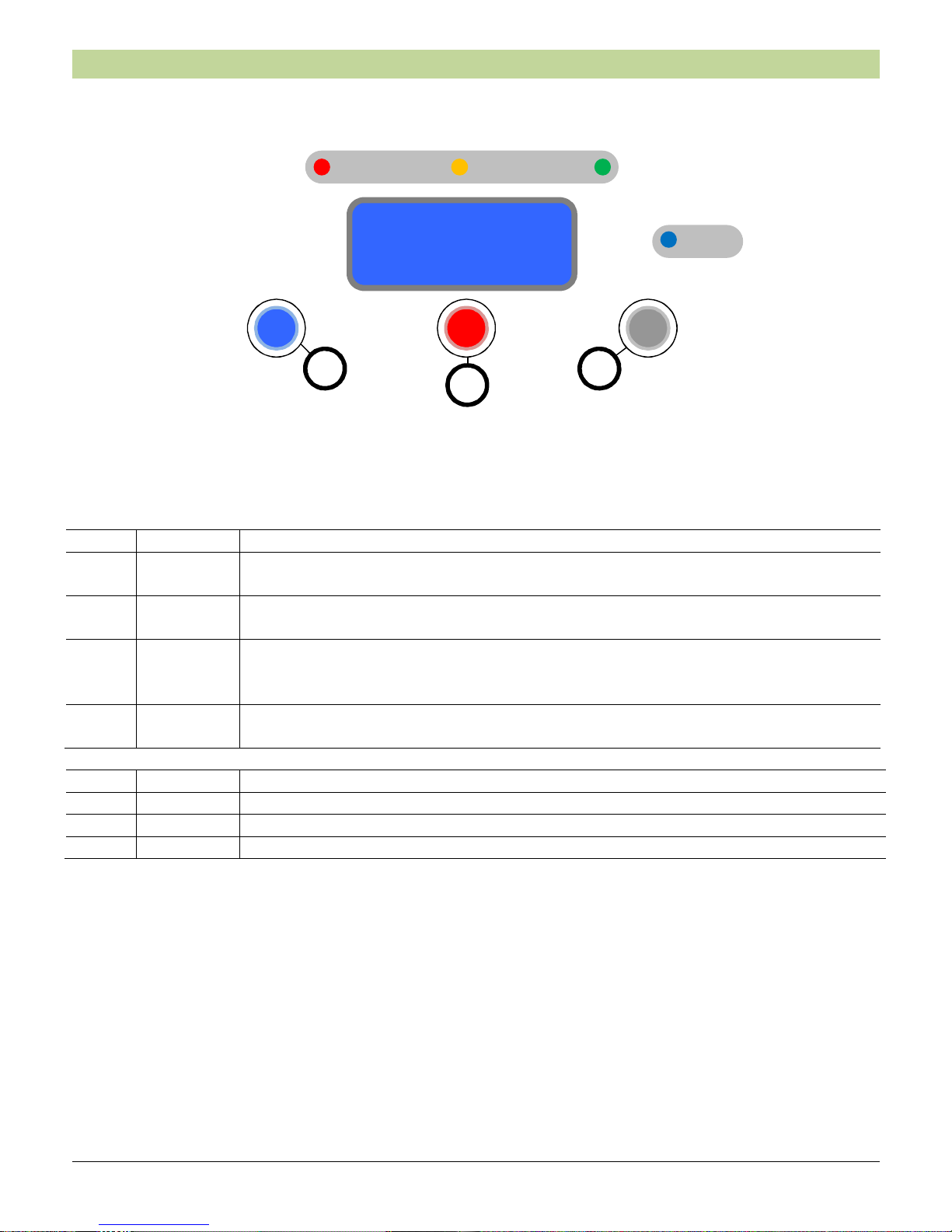
2. PANEL: DISPLAY AND BUTTONS
CE 60-3 GSM Panel
LED Colour SIGNALS
L1 RED
Total Arming >Solid light
Alarms Memory Flashing
L2 YELLOW
Partial/External Arming Solid light
“Open Door” Signal Flashing
L3 GREEN
Electrical power supply presence Solid light
If the indicator LED doesn’t lit up, be sure that it is not due to a power line failure (e.g.
the “automatic circuit breaker” is been released or there is a blackout).
ALERT BLUE
ALERT function activated Solid light
Wireless code transmission Flashing
Button Function
X Options Inclusion-exclusion Outdoor zones / User menu / Alert
O Selection Alarm memory / GSM Menu / Credit request
# Menu Control panel version / Control panel Test / Scroll voices
ComCE
Ce603 v4.0
L1 L2 L3
ALERT
X #
O

7
3. WIRELESS CODE TRANSMISSION
The control panel transmits via radio instructions and control codes to the devices.
The control panel displays the transmission with the BLUE “ALERT” led flashing.
During the transmission, the control panel is unable to receive wireless instruction signals, for this reason it is
common that in these moments the control panel does not answer to the instructions given for example with a
remote control. In this case it is enough to wait for a while until the transmission is completed (the blue led
stops flashing) and make the transmission again.
Wireless code
To enable the transmission of the Wireless Codes, learn an activator in position 1.
ALERT

8
4. CONTROL PANEL USE
4.1. Information on display
The control panel shows (when disarmed) on the LCD display:
4.2. Arming table
Each sensor can be programmed to be associated to only one of the three arming types [T=Total, P=Partial,
E=Outdoor] allowed by the control panel:
• TOTAL
Sensors included: T + P + E or T + P (if E are excluded)
• PARTIAL
Sensors included: P + E or P (if E are excluded)
• OUTDOOR
Sensors included: E (even if E is excluded from Total and Partial)
Note: if no sensor is set as T, P or E, the corresponding arming IS NOT EXECUTED.
The sensors programmed as OUTDOOR (E) can be excluded from Total and Partial arming:
• Wait for 2 minutes from the last disarming
• Keep pressed the “X” button of the control panel
• Change the status of the inclusion/exclusion of the sensors E (“excluded included” or “included
excluded”) and a message is displayed:
• On the display – at rest – the status changes:
12:30 06/02/12 =
Disarmed ▄ O
Outdoor sensors
Excluded
Outdoor sensors
Included
When the sensors are excluded
from Total and Partial
When the sensors are included
from Total and Partial
12:30 06/02/12 =
Disarmed ▄ O
12:30 06/02/12 =
Disarmed ▄ X
“O”: the sensors E are included
in Total and Partial
“X”: the sensors E are excluded
from Total and Partial
Time and date Relay AUX status: “=” disabled, “–“ enabled
Arming status GSM signal level (if present) Outdoor exclusion zones
9
• The control panel records and maintains the status of the exclusion that has been set. To change it
repeat the procedure.
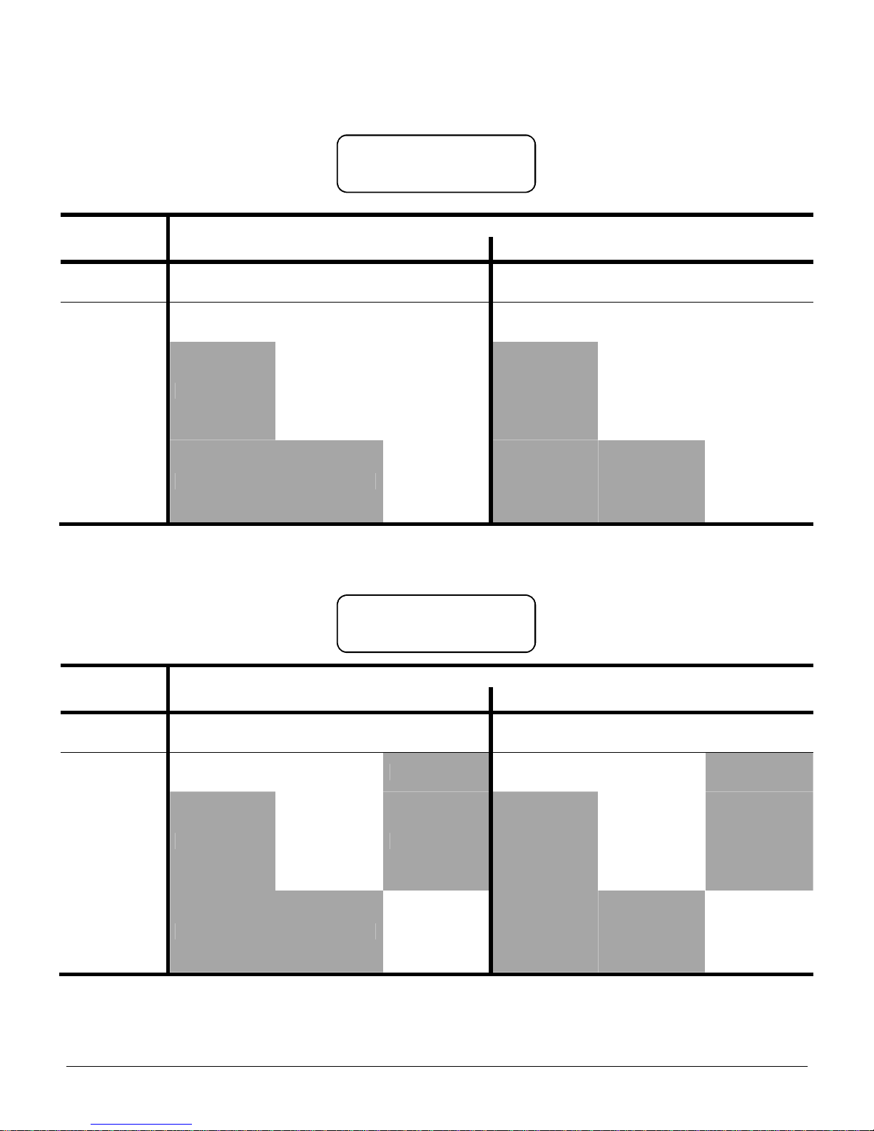
Outdoor sensors included
Arming type
Control panel actions in case of detection
Outdoor Beeps ON Outdoor Beeps OFF
Total
Sensors
Partial
Sensors
Outdoor
Sensors
Total
Sensors
Partial
Sensors
Outdoor
Sensors
TOTAL
Alarm
(3 minutes)
Alarm
(3 minutes)
Bell
(60 seconds)
Alarm
(3 minutes)
Alarm
(3 minutes)
Alarm
(3 minutes)
PARTIAL Not working
Pre-alarm
(0-60 seconds)
+
Alarm
(3 minutes)
Bell
(60 seconds)
Not working
Pre- alarm
(0-60 seconds)
+
Alarm
(3 minutes)
Pre- alarm
(0-60 seconds)
+
Alarm
(3 minutes)
OUTDOOR Not working Not working
Bell
(60 seconds)
Not working Not working
Pre-alarm
(0-60 seconds)
+
Alarm
(3 minutes)
Outdoor sensors excluded
Arming Type
Control panel actions in case of detection
Outdoor Beeps ON Outdoor Beeps OFF
Total
Sensors
Partial
Sensors
Outdoor
Sensors
Total
Sensors
Partial
Sensors
Outdoor
Sensors
TOTAL
Alarm
(3 minutes)
Alarm
(3 minutes)
Not working
Alarm
(3 minutes)
Alarm
(3 minutes)
Not working
PARTIAL Not working
Pre-alarm
(0-60 seconds)
+
Alarm
(3 minutes)
Not working Not working
Pre-alarm
(0-60 seconds)
+
Alarm
(3 minutes)
Not working
OUTDOOR Not working Not working
Bell
(60 seconds)
Not working Not working
Pre-a
larm
(0-60 seconds)
+
Alarm
(3 minutes)
Note: Outdoor arming does not consider the exclusion of the sensors E. Outdoor arming ALWAYS activates the
sensors for the alarm detection.
12:30 06/02/12 =
Disarmed ▄ O
12:30 06/02/12 =
Disarmed ▄ X
10
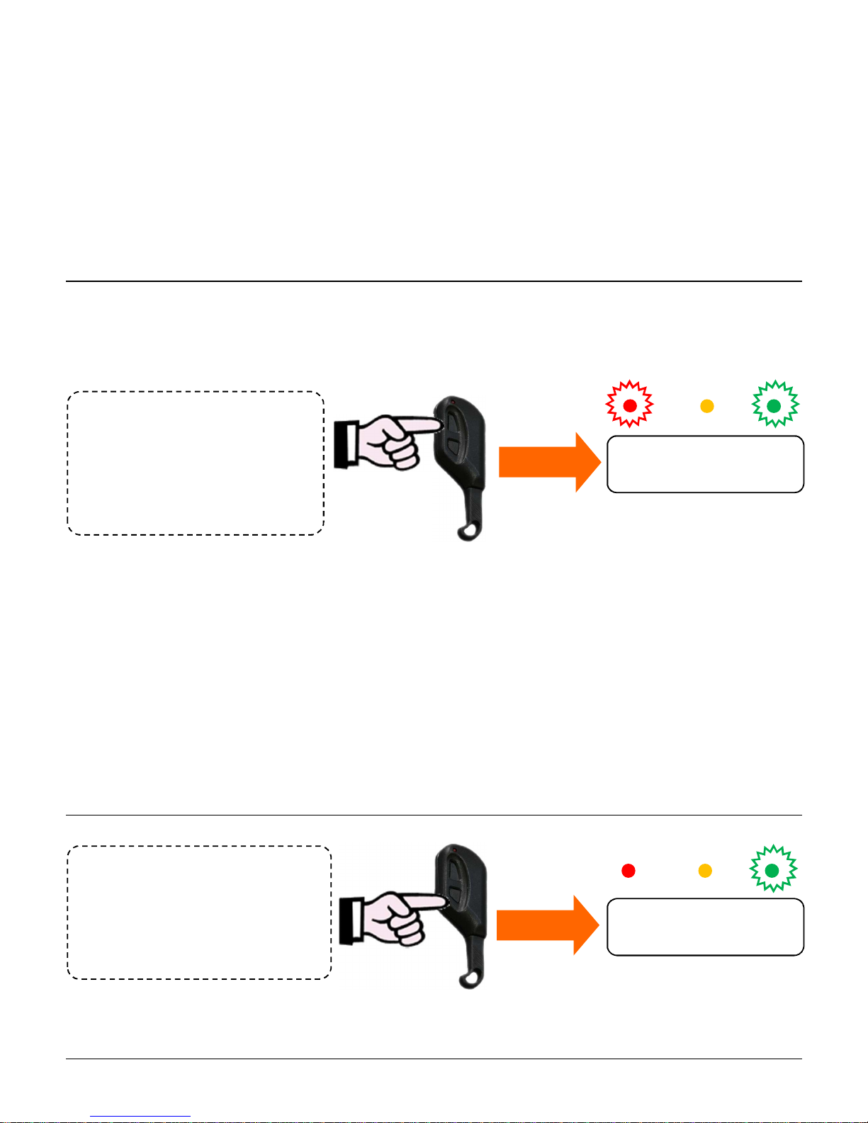
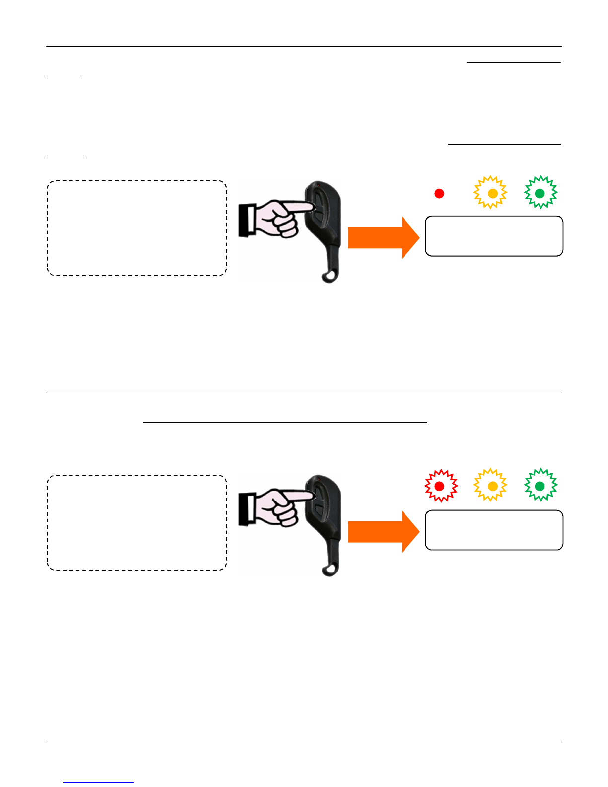
TOTAL
arming
• Press once the BIG button of the
remote control
• Pass once the CHT key
• Arm with the DVTR-RT keypad
Disarming
• Press once the SMALL button of the
remote control
• Pass once the CHT key
• Disarm with the DVTR-RT keypad
Alarm > High powered sound from indoor and outdoor siren.
Duration: 3 minutes (can be modified)
Pre-alarm > (to enable if desired) Acoustic warning from indoor siren before the alarm.
Duration: 60 seconds (can be modified)
Bell > (only from outdoor sensors) Acoustic warning from indoor siren.
Duration: 60 seconds (can be modified)
4.3. TOTAL arming
The system is TOTALLY activated (red led L1 lit up) when you want to arm the control panel detecting breakings
and entering, whenever any sensor (excluded ones excepted) detects a movement.
This type of arming is normally used when you are out of the house.
All sensors detecting breakings and entering will activate the control panel siren.
The alarm period is 3 minutes for each event, and it can be repeated up to 4 times for the signal coming from a
single sensor during the same arming time, and anyway up to a 10 times maximum.
Warning: see the behaviour in case of open doors in the next related chapter.
Warning: always verify in the display that the Outdoor sensors are included (“O” symbol) or excluded ( “X”
symbol).
4.4. Disarming/Blocking of on-going alarms
12:30 06/02/12 =
Total Armed ▄ X
12:30 06/02/12 =
Disarmed ▄ X
11
PARTIAL arming
• Press twice the BIG button of the
remote control
• Pass twice the CHT key
• Arm with the DVTR-RT Keypad
OUTDOOR Arming
• Press 3 times the BIG button of the
remote control
• Pass 3 times the CHT key
• Arm with the DVTR-RT Keypad
4.5. PARTIAL arming
The PARTIAL arming (yellow led L2 lit up) is useful if you are interested in activating just a certain number of
sensors (set up as PARTIAL and/or OUTDOOR).
A classic example of partitioning is the definition of the perimeter zone; it is to say grouping all sensors
defending the perimeter of the protected area (on-doors sensors, windows and shutters, garden).
For example, at night, when the user is at home (and therefore he should not be detected), it is necessary to
check only doors and windows (environmental perimeter). In this type of arming infrared sensor are not
working.
Warning: see the behaviour in case of open doors in the next related chapter.
Warning: always verify in the display that the Outdoor sensors are included (“O” symbol) or excluded ( “X”
symbol).
4.6. OUTDOOR arming
The OUTDOOR arming is a special arming mode in order to activate exclusively a detecting area outside the
building (sensors E); the sensors T (perimeter) and P (indoor) will not be activated and will not report alarm or
intrusion in case of activity within the areas controlled by them.
For example, it can be used when the user likes to move freely within the building being sure of the presence of
an alarm in case of any potential intrusion from the outside (area controlled by Outdoor sensors).
Warning: the sensors E will be activated even if their exclusion is set: the exclusion is valid only for Total
and Partial arming).
Warning: If the function “Beeps from Outdoor Sensors” is been activated, the sensors set up as Outdoor, if
alerted, will only cause a 60 seconds beeps.
If the function “Beeps from Outdoor Sensors” is been deactivated the Outdoor sensors will
generate alarm in case of detection.
Warning: see the behaviour in case of open doors in the next related chapter.
12:30 06/02/12 =
Part. Armed ▄ X
12:30 06/02/12 =
Outdoor Arm. ▄ X
 Loading...