

Duerkopp Adler N291 Service Manual

Contents: Page:
General safety instructions
Service manual N291
1. Set of gauges and handwheel positions
1.1 Parts of the set of gauges . . . . . . . . . . . . . . . . . . . . . . . . . . . . . . . . . . . . . 5
1.2 Adjustments in the different handwheel positions . . . . . . . . . . . . . . . . . . . . . . . . 6
2. Sewing machine
2.1 Adjustment disk . . . . . . . . . . . . . . . . . . . . . . . . . . . . . . . . . . . . . . . . . . 8
2.2 Stitch regulator . . . . . . . . . . . . . . . . . . . . . . . . . . . . . . . . . . . . . . . . . . . 10
2.3 Feed dog . . . . . . . . . . . . . . . . . . . . . . . . . . . . . . . . . . . . . . . . . . . . . . 12
2.4 Needle bar frame . . . . . . . . . . . . . . . . . . . . . . . . . . . . . . . . . . . . . . . . . . 14
2.5 Hook, needle bar, hook guard and thread sluice . . . . . . . . . . . . . . . . . . . . . . . . 16
2.6 Dials . . . . . . . . . . . . . . . . . . . . . . . . . . . . . . . . . . . . . . . . . . . . . . . . . 22
2.7 Sewing feet . . . . . . . . . . . . . . . . . . . . . . . . . . . . . . . . . . . . . . . . . . . . . 24
2.8 Sewing foot lift and thread tension release . . . . . . . . . . . . . . . . . . . . . . . . . . . 27
2.9 Thread regulator . . . . . . . . . . . . . . . . . . . . . . . . . . . . . . . . . . . . . . . . . . 30
2.10 Check spring . . . . . . . . . . . . . . . . . . . . . . . . . . . . . . . . . . . . . . . . . . . . 30
2.11 Oil lubrication . . . . . . . . . . . . . . . . . . . . . . . . . . . . . . . . . . . . . . . . . . . . 31
2.12 Speed limitation with greater sewing foot strokes and stitch lengths . . . . . . . . . . . . . 33
3. Thread trimmer
3.1 Function sequence . . . . . . . . . . . . . . . . . . . . . . . . . . . . . . . . . . . . . . . . . 34
3.2 Activation timing of the bobbin brake . . . . . . . . . . . . . . . . . . . . . . . . . . . . . . 34
3.3 Braking effect of the bobbin brake . . . . . . . . . . . . . . . . . . . . . . . . . . . . . . . . 34
3.4 Position of the cam . . . . . . . . . . . . . . . . . . . . . . . . . . . . . . . . . . . . . . . . 35
3.5 Position of the cylinder . . . . . . . . . . . . . . . . . . . . . . . . . . . . . . . . . . . . . . 35
3.6 Height of the thread catcher . . . . . . . . . . . . . . . . . . . . . . . . . . . . . . . . . . . 35
3.7 Thread catcher range of motion . . . . . . . . . . . . . . . . . . . . . . . . . . . . . . . . . 36
3.8 Pressure of the counter knife on the thread catcher . . . . . . . . . . . . . . . . . . . . . . 36
3.9 Position of the bobbin thread clamp . . . . . . . . . . . . . . . . . . . . . . . . . . . . . . . 36
3.10 Position of the released thread tension assembly . . . . . . . . . . . . . . . . . . . . . . . 36
3.11 Pressure of the thread pre-tension . . . . . . . . . . . . . . . . . . . . . . . . . . . . . . . . 36
4. Synchronizer
4.1 Reference position . . . . . . . . . . . . . . . . . . . . . . . . . . . . . . . . . . . . . . . . . 38
4.2 1st and 2nd position . . . . . . . . . . . . . . . . . . . . . . . . . . . . . . . . . . . . . . . . 39
4.3 Stop position after "needle re-positioning" from the 2nd position . . . . . . . . . . . . . . . 39
5. Changing the elements
5.1 Changing the hook . . . . . . . . . . . . . . . . . . . . . . . . . . . . . . . . . . . . . . . . . 40
5.2 Changing the PC-board . . . . . . . . . . . . . . . . . . . . . . . . . . . . . . . . . . . . . . 40

1. Set of gauges and handwheel positions
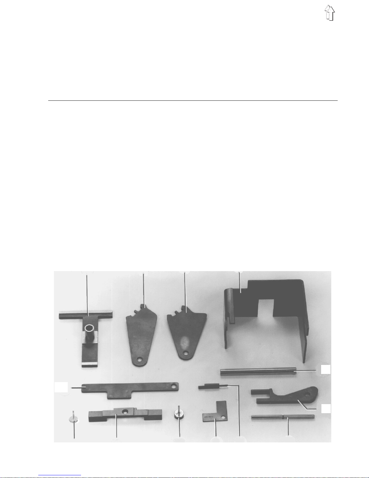
1.1 Parts of the set of gauges
The pin 7 of the 13-part set of gauges (parts no. 491 79991) is also incorporated in the accessories of
every machine. It is thus possible to lock the handwheel in the positions A, B, C, D, E and F, even without
the set of gauges.
Gauge Parts no. Adjustment
Gauge 1 244 1001 – Height of the hook shaft
Gauge 2 491 79995 – Timing of the sewing foot stroke motion
Gauge 3 491 79994 – Timing of the sewing foot feed travel
Gauge 4 with 491 80001
Pin 5 742 52082
– 0-position of the "bottom" stitch regulator
Gauge 6 491 79997
– 0-position of the "top" stitch regulator
Pin 7 791 8110
– Locking the ha nd wh ee l in t he de s i red po s iti o ns
– Equalizing the foot strokes
– Position of the adjustment disk and further
elements
Gauge 8 244 1014 – Distance between the hook and needle
Gauge 9 241 1011 – Distance between the thread catcher and
thread trimmer
Pin 10 244 1009
– Needle bar height for needle system 2134-35
DU KK
Measuring
bridge 11 212 4942
– Needle bar he i gh t
– Feed dog height
Pin 12 244 1008
– Needle bar height for needle system 134 KK
Gauge 13 491 79996
– Foot stroke adjustment range
1 2 3 4
5
6
12 11 10 9 8 7
13
5

1.2 Adjustments in the different handwheel positions
For some adjustments the needle bar or take-up lever must be in a defined position.
This position is marked by letters on the handwheel 3 and can be locked as follows:
– Turn the handwheel i nt o t he position def i ne d f or the adjustment .
– Slide the ti m i ng pi n 1 into the hole 2 of the housing.
– Turn the handwheel s l i gh tl y forward and back ward until the timing pin can be sl i d a l l th e w ay i n to th e
respective slot of the adjustment disk 4.
Only with po si ti o n F t he pi n mu s t re s t a ga i ns t th e r e spective side of th e c u to ut .
Slot Position Adjustment
A Needle bar 2 mm behind the
lower dead poi nt
– Position of th e a dj u s tm en t d i s k on th e arm shaft
– Loop stroke
– Needle bar h ei g ht ( wi t ho ut ga ug e)
– Distance between the hook and needle
B Needle bar ne ar ing its upper
dead point
– Timing of the feed ing foot feed travel (w i th
gauge)
C Take-up lever nearing its upper
dead point
– Position of th e t hr e ad tri m me r c am
D Take-up lever nearing its lower
dead point
– Timing of the feeding foot stroke motion
– Setting the reference position of the
synchronizer
E Needle bar at th e l o we r de ad
point
– Distance between the feeding foot bar and
sewing foot bar
– Checking the timing of the feeding foot feed
travel
– Needle bar height (with gauge)
– Timing of the feed do g f ee d t r ave l
F Shortly behind the loop stroke
– Synchronizer (1st position)
6

1 2 3
1
4
D
F
A
E
B
C
G
7

2. Sewing machine
Turn off main switch!
Otherwise there is danger of injury!
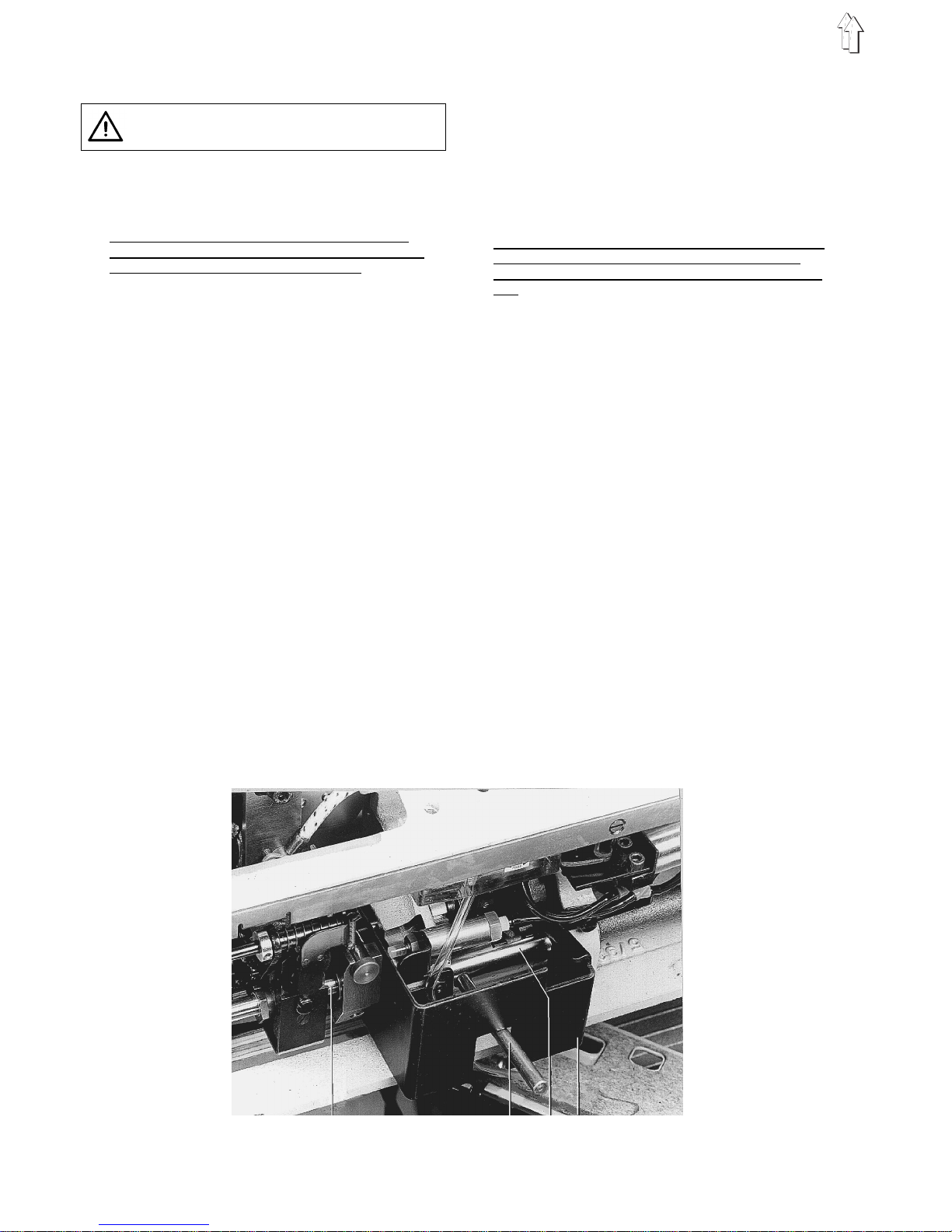
2.1 Adjustment disk
Explanati on:
The positions locked with the timing pin 1 are
only correct, when the adjustment disk 4 has
been adjusted ac c o rdi n g t o t he rule.
Rule:
The groove in the arm shaft crank 3 and the
lowest slot i n t he ad j us t me nt di s k 4 mu s t b e
aligned.
Check:
– Slide the pi n 2 (5 mm Ø) of the set of gauges
through the hole of the housing all the way into
the groove of the arm shaft crank 3.
– Push the ti m i ng pi n 1 t hrough the hole of the
housing right ag ai n s t t he ad j us t me nt di s k .
When the pin is located in the deepest slot of
the adjustment disk, the adjustment disk is
positioned correctly. In this case, the ring
groove in the timing pin is no longer visible.
Correction:
– Move the ti mi n g b el t 5 o n t he up per timing
pulley 6 to the left until its 2 screws are
accessible.
To do this, use a round pin and turn the
handwheel.
– Loosen the t wo s c rews at the timin g p ul le y 6.
– Slide the pi n 2 (5 mm Ø ) th r ou gh th e h ole al l
the way into th e g r oo ve o f the arm shaft c ran k 3.
– Slide the ti m ing pi n 1 t hr o ug h t he ho l e in th e
housing.
– Turn the timing pulley until the timing pin 1 can
be slid into the deepest slot of the adjustment
disk 4.
– Tighten both scr ew s at th e t i mi n g p ul l e y.
At the same time shift the timing pulley to the
right against th e timing pin 1.
– Remove both pi n s .
– Turn the handwheel un ti l t he ti m i ng be l t i s
again centred on the timing pulley.
2
1
8

1
4
D
F
A
E
B
C
G
2
3
6 5
9
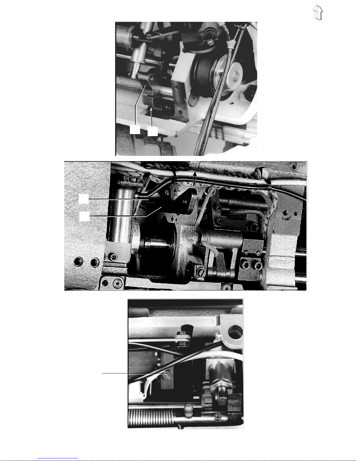
2.2 Stitch regulator
Turn off main switch!
Otherwise there is danger of injury!
2.2.1 Stitch regula tor 0-position for the bottom
feed
Rule:
The feed dog sh ou l d p erf or m th e m i ni m um
possible feed tra v el , wh en th e re s pe cti v e dia l
has been set at th e s t i tc h l en gt h " 0 " .
Check:
– Set the stitch length "0".
– Lock the sewing feet in their lifted position.
– Turn the handwheel.
Pre-adjustment with gauge:
– Slide the ga ug e 1 on to th e c o ul i s se s ha ft 2 and
axle 4.
– Insert the pin of the gauge 3 (8 mm) into the
hole of the coulisse shaft 2.
– Loosen the screw 5 at the block 6.
– Turn the coulisse shaft until the pin of the
gauge rests against the edge o f t he gauge.
– Tighten the scre w 5 .
– Check the adjustment, and if necessary correct.
Correction:
– Loosen the screw 5.
– Insert a pin into the hole of the coulisse shaft 2.
– Turn the coulisse shaft accordingly using the
pin.
2.2.2 Stitch regula tor 0-position of the top feed
Rule:
The needle and the feeding foot should perform
the minimum pos s ibl e fe ed tr a vel , wh en th e
respective dial has been set at the stitch length
"0".
Check:
– Set the stitch length "0".
– Turn the handwheel.
Pre-adjustment with gauge:
– Loosen the screw 9.
– Insert the gauge 8 into the hole of the coulisse
shaft 7 and push it against the flat at the arm.
– Tighten the scre w 9 .
Correction:
– Loosen the screw 9.
– Insert the pin into the hole of the coulisse
shaft 7.
– To increase the feed travel:
turn the coulisse shaft 7 towards (+).
– To decrease the fe ed travel:
turn the coulisse shaft 7 towards (–).
– Tighten the scre w.
4 3 2 1
10
6
5
7
8
9
11

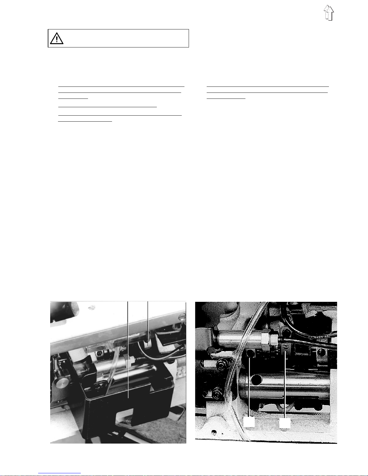
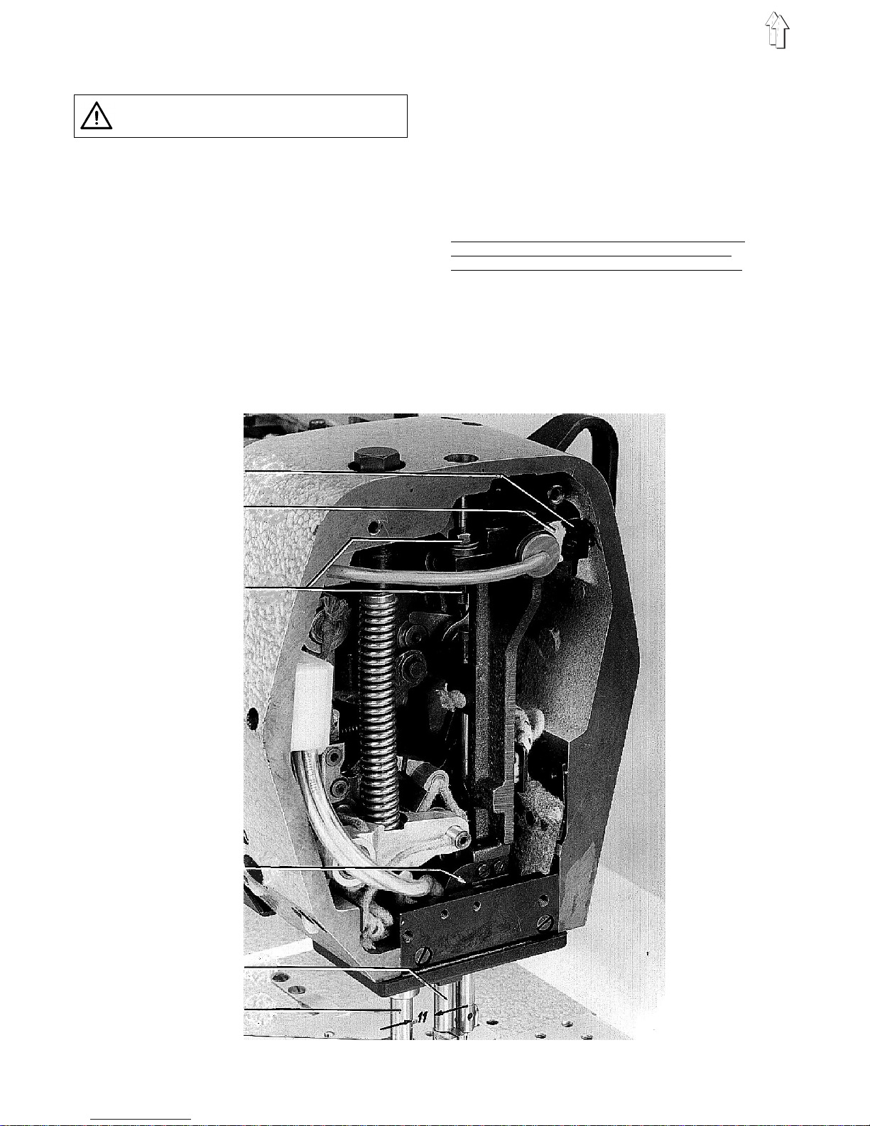
2.3 Feed dog
Turn off main switch!
Otherwise there is danger of injury!
2.3.1 Feed dog position in the throat plate
cutout
Prerequisi te:
Correct distance between the feeding foot bar
and cloth presser bar. (See 2.4.2).
Rule:
– In line of feed motion:
The feed dog sh ou l d b e a l igned such that i n
line of feed motion the needle enters at the
centre of the needle hole.
–
Across the line of feed motion:
The feed dog sh ou l d b e centred in the th r oa t
plate cutout.
Correction i n l i ne of fe ed motion:
Loosen the sc rew at the feed lev er 4 an d
change the position of the feed dog holder 2
accordingly.
Correction across the li ne of fe ed mo ti o n:
– In the case of small deviations:
Change the posit i on of th e f ee d d og on i ts
holder 2 accordingly.
– In the case of greater deviations:
Loosen the sc rews at the stroke l ev e r 1 and
feed lever 4.
Change the posi t i on of th e feed dog holder 2
accordingly.
2.3.2 Feed dog height
Rule:
At its highest point of travel the feed dog
should extend above the throat plate by 0.5 mm.
In this positi o n t he feed dog shoul d a l s o b e
parallel to th e throat plate.
Check:
– Lock the sewing feet in their lifted position.
– Turn the handwheel un ti l t he fe ed dog has
reached its highest point of travel.
– Check whet he r th e h ei g ht is c orr e ct u s i ng th e
gauge 5 or a feel e r gauge.
Correction:
– Loosen the screw at the stroke lever 1 and
change the height of the feed dog holder 2
accordingly.
– Slightl y l oo s en th e s c re w s a t the feed dog and
turn the supporting screw 3 accordingly.
1
2
3
4
5
12
Turn off main switch!
Otherwise there is danger of injury!
2.3.3 Timing of the feed dog feed travel
Rule:
When the stitch regulator lever is actuated, the
needle bar must not move under the following
conditions:
–
Maximum stitch length has been set.
–
Handwheel lock e d in po s i tio n E ( n ee dle at th e
bottom of its stroke)
Adjustment w i th ga uge:
– Loosen the screws at the eccentric 2.
– Slide the gauge 1 onto the coulisse shaft and
axle.
– Lock the handwheel in position E.
– Turn the eccentric until the gauge can
submerge in i ts g r oo v e.
– Slide the eccentric to the right against the
bearing.
– Tighten the screws at the eccentric.
Correction:
– Loosen the screws at the eccentric 2 and turn
the eccentric accordingly.
The eccentric is positioned correctly, when not
only the rule is fulfilled, but also the slot of the
eccentric points downward. If this is not the
case, turn the eccentric by 180°.
– Move the ecc e nt ri c to th e r ight against the
bearing.
– Tighten the screws at the eccentric.
2.3.4 Timing of the feed dog stroke motion
Rule:
When the needle is at the bottom of its stroke
the feed dog sh ou l d h av e r ea c he d its highest
point of travel.
Check:
– Lock the sewin g f ee t i n th ei r l i f te d p osi t i on .
– Set the stitch length "0".
– Turn the handwheel.
Pre-adjustment:
When the feed eccentric 2 is adjusted correctly,
proceed as fol l o ws f or t he pre-adjustment :
– Loosen the screws at the stroke eccentric 3
and turn it on the shaft until the 1st screw (seen
in direction of rotation) of the stroke eccentric
is aligned with the 2nd screw of the feed
eccentric.
– Move the stroke eccentric to the right until it
touches the oil leather strip 4.
– Tighten the screws.
Correction:
Loosen the screws and turn the stroke
eccentric 3 on the shaft accordingly.
1 2
3
4
13
2.4 Needle bar frame
Turn off main switch!
Otherwise there is danger of injury!
2.4.1 General information
– The stop screw 5 that is sealed with yellow
paint and is secured with glue to prevent i t f rom
turning must rest against the inside of the arm
casting.
– The left gu i de bo l t 3 (w ithin the frame) and the
right guide bolt 7 (within the arm) were adjusted
at the factory su c h t ha t t he ne ed l e b ar frame
moves smooth ly an d without cleara nc e .
Therefore, the position of the two guide bolts
must not be changed.
– Using the nuts 4 the frame holder 6 must be
adjusted such that it is parallel with the bottom
edge of the arm h ea d.
2.4.2 Distance between the feeding foot bar
and cloth presser bar
Rule:
The distance between the bars 1 and 2 should
be 11 mm, when the handwheel is loc ke d i n
position E (n ee dl e at th e b ottom of its str o ke) .
Correction:
– Lock the hand wh ee l i n p osi t i on E.
– Remove the p l ug 9 a nd loosen the scr e ws
behind.
– Turn the eccentric 8 accordingly.
6
5
4
3
2
1
14
 Loading...