


Anbauanleitung für Barcodeleser
Teilesatz 0911 597554
Fitting Instructions Barcode Reader
Kit 0911 597554
1 Komponenten des Teilesatzes
Der Teilesatz besteht aus folgenden Bauteilen:
Menge Bezeichnung Material-Nr.
1 9850 911006 Scanner Barcode
1 0911 562810 Winkel
2 9202 021648 Zylinder Schraube M3 x 5
2 9231 110035 6kant Mutter M3
2 9330 200077 Scheibe A3,2
1 9870 911016 Leitungssatz komplett Scanner
3 9223 000930 Zylinderschraube M1,6 x 5
1 9850 911004 Pegelwandler
4 9841 121002 Kabelbinder
1 9850 911005 Leitung komplett Netzteil
3 9830 501025 Distanzhülse
3 9203 003737 Zylinderschraube M4 x 25
Teile-Nr./ Part-No.:
0791 911702
2 Barcodetypen
Folgende Barcodetypen können vom Barcodeleser gelesen werden:
Code 128
·
UCC EAN 128
·
Code 39
·
Diese Barcodetypen können mit Freeware-Software selbst erstellt
werden. Dabei ist zu beachten dass der Barcode 3 bis 10 Zeichen
beinhalten muss.
oder
Sie nutzen die auf der letzten Seite zur Verfügung gestellten Barcodes.
Ausgabe/Edition:
03.2011
Änderungsindex
Rev. index: 00.0
Printed in Germany
Blatt: von
Sheet: 1 from 16
Anbauanleitung für Barcodeleser
Teilesatz 0911 597554
Fitting Instructions Barcode Reader
Kit 0911 597554
3 Teilesatz montieren
Vorsicht Verletzungsgefahr!
Hauptschalter ausschalten.
Teilesatz nur bei ausgeschalteter Nähanlage montieren.
3.1 Netzteil montieren und anschließen
Teile-Nr./ Part-No.:
0791 911702
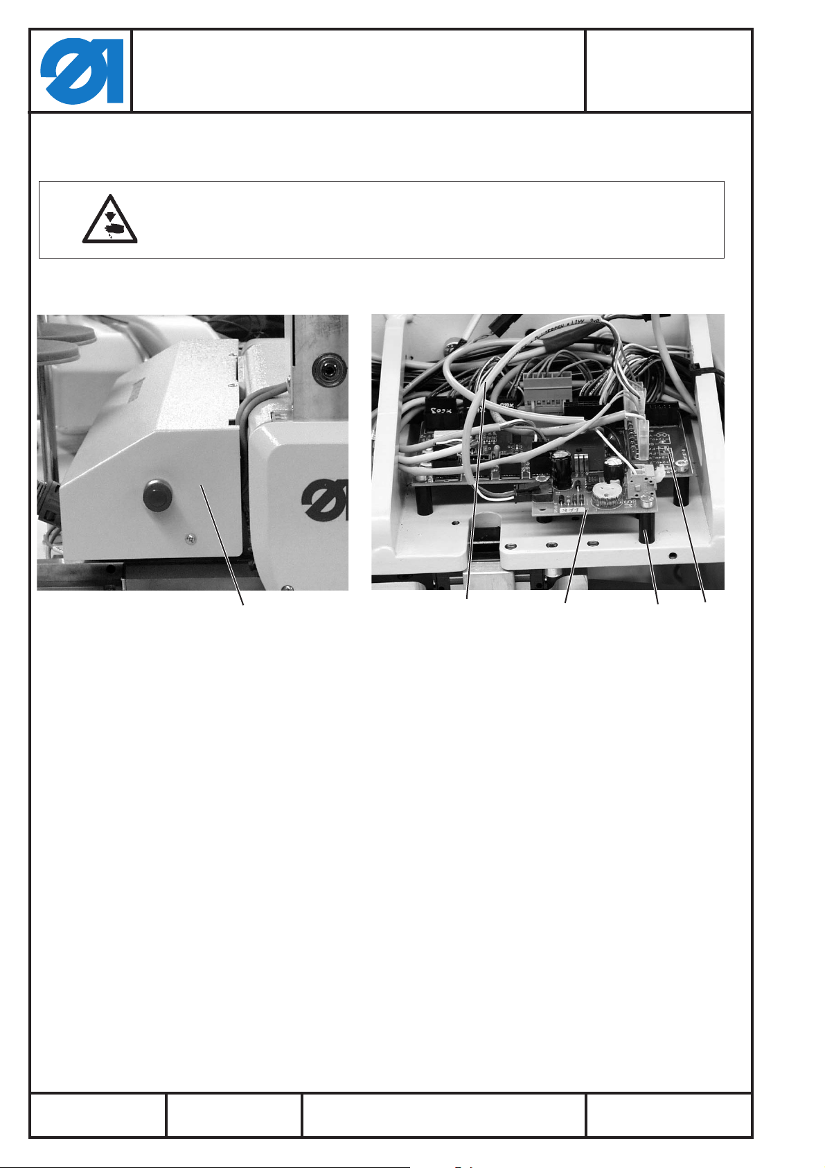
1
– Linke Abdeckhaube 1 entfernen.
–
Netzteil 4 mit Distanzhülsen 3 und Zylinderschrauben
M 4 x 25 montieren.
–
Leitung 5 (22 cm aus 9870 911016) mit 3 pol. Steckverbindung
des Netzteils 4 verbinden.
–
Leitung 5 an 10 pol. Flachstecker von Leiterplatte 2
anschließen:
weißan8(+24V-1)
grün an 10 (GND)
Z. Zeit braun an 10 (GND) = Netzteil immer aktiv
Ab Baujahr 2011:
braun an 9 (Y9) = Netzteil mit Ausgang 21 am Bedienfeld
schaltbar.
5432
Ausgabe/Edition:
03.2011
Änderungsindex
Rev. index: 00.0
Printed in Germany
Blatt: von
Sheet: 2 from 16
Anbauanleitung für Barcodeleser
Teilesatz 0911 597554
Fitting Instructions Barcode Reader
Kit 0911 597554
3.2 Zuleitung zur Steuerung verlegen und anschließen
Teile-Nr./ Part-No.:
0791 911702
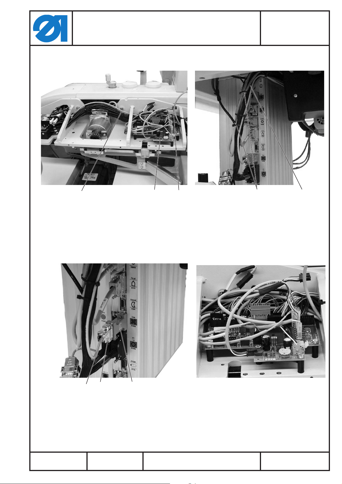
21A
– Zuleitung 2 (1,9 m lang aus 9870 911016) von A nach B parallel
zum Kabelbaum 3 verlegen und mit mehreren Kabelbindern 4
an diesem befestigen.
– Die weiße und die schwarze Ader mit den Federklemmen von
Netzteil 1 verbinden.
Schwarz an SW (0V)
Weiß an WS (+ VCC)
43
43
Ausgabe/Edition:
03.2011
B6 5
–
Änderungsindex
Rev. index: 00.0
Stecker 6 mit Pegelwandler 5 in die Dose X150b an der
Steuerung stecken und mit den Schrauben sichern.
Printed in Germany
Blatt: von
Sheet: 3 from 16
Anbauanleitung für Barcodeleser
Teilesatz 0911 597554
Fitting Instructions Barcode Reader
Kit 0911 597554
3.3 Winkel und Scanner montieren
Teile-Nr./ Part-No.:
0791 911702
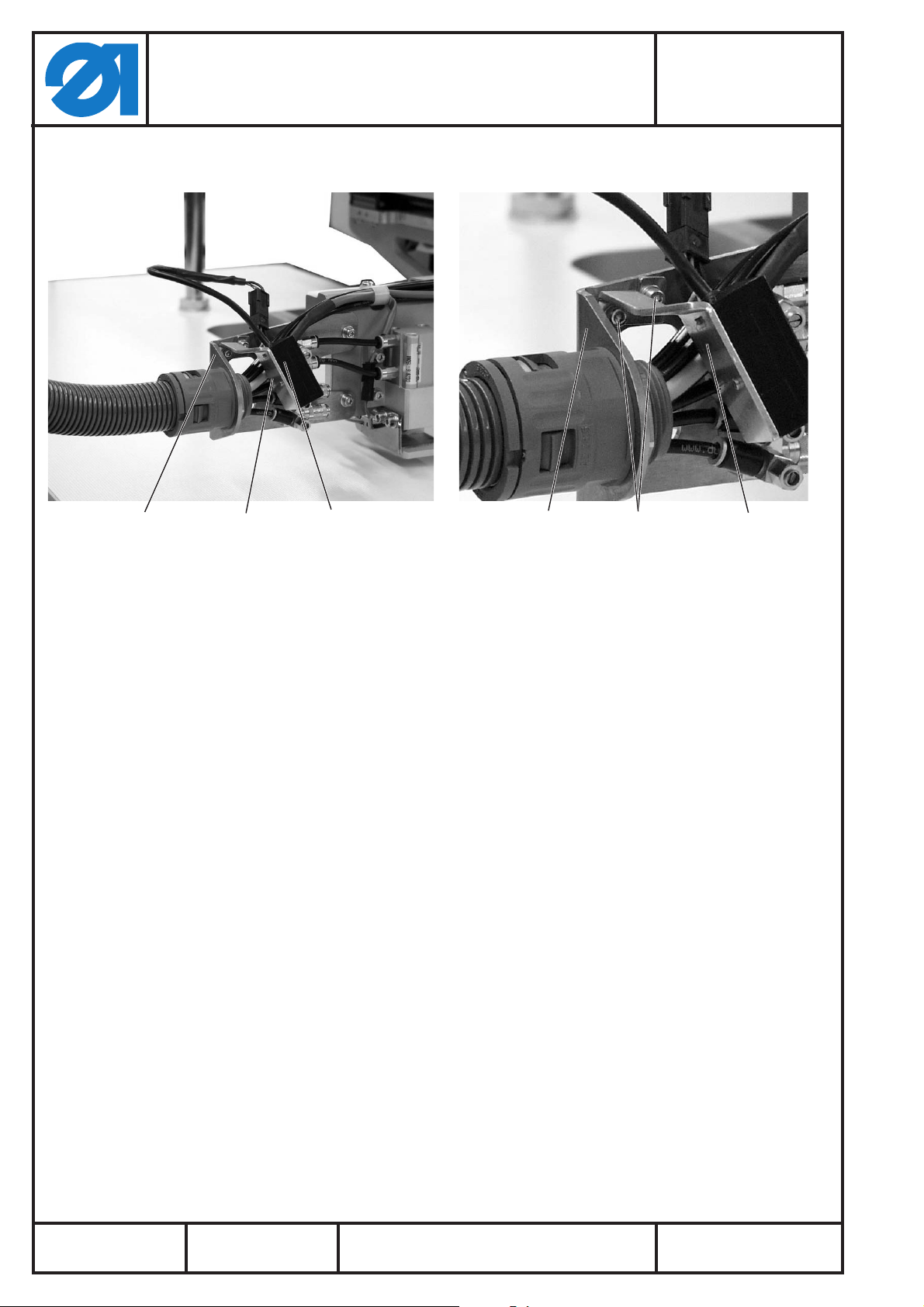
314
– Scanner 4 mit zwei Schrauben M1,6 x 5 am Winkel 1 montieren.
– Winkel 1 mit zwei Schrauben 2 (M 3 x 5), Unterlegscheiben und
Muttern am Transportschlitten 3 befestigen.
32 1
Ausgabe/Edition:
03.2011
Änderungsindex
Rev. index: 00.0
Printed in Germany
Blatt: von
Sheet: 4 from 16
Anbauanleitung für Barcodeleser
Teilesatz 0911 597554
Fitting Instructions Barcode Reader
Kit 0911 597554
3.4 Leitungssatz zum Scanner verlegen und anschließen
Teile-Nr./ Part-No.:
0791 911702
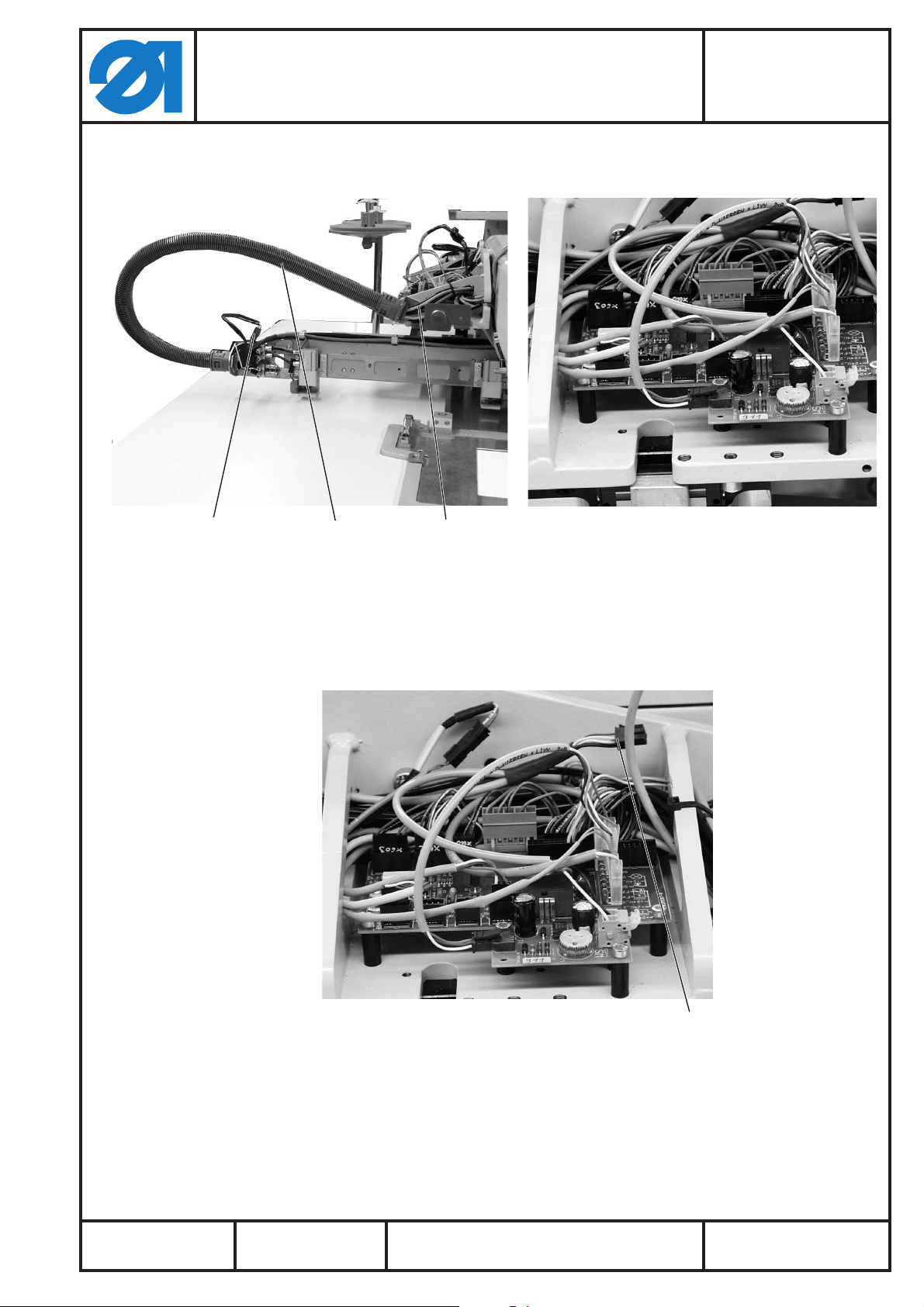
321
– Leitung 1 (1,2 m aus Leitungssatz 9870 911016) durch den
Schlauch2ziehenoderaußenamSchlauch2mitKabelbindern
befestigen (6 pol. Buchsenleiste zum Scanner).
– 6 pol. Stiftleiste von Leitung 1 mit 6 pol. Buchsenleiste 4
verbinden.
– Steckverbindung 3 am Scanner herstellen.
Ausgabe/Edition:
03.2011
Änderungsindex
Rev. index: 00.0
Printed in Germany
4
Blatt: von
Sheet: 5 from 16

3.5 Barcode aufkleben
Anbauanleitung für Barcodeleser
Teilesatz 0911 597554
Fitting Instructions Barcode Reader
Kit 0911 597554
Teile-Nr./ Part-No.:
0791 911702
1
– Den erzeugten Barcodestreifen 1 auf die linke Klammerseite
kleben.
3.6 Barcodeleser aktivieren (siehe auch Bedienanleitung Kapitel 7.7.4)
Ausgabe/Edition:
03.2011
–
–
–
–
–
Änderungsindex
Rev. index: 00.0
Nähanlage einschalten.
Bearbeiten -> Maschinenparameter antippen.
MP1 - Konfiguration antippen.
Optionale Einrichtungen antippen.
Barcodeleser einschalten.
Printed in Germany
Blatt: von
Sheet: 6 from 16

Anbauanleitung für Barcodeleser
Teilesatz 0911 597554
Fitting Instructions Barcode Reader
Kit 0911 597554
3.7 ID vergeben (siehe auch Bedienanleitung Kapitel 7.7.1)
Bearbeiten -> Nahtprogramm -> Nahtparameter antippen.
–
PP1 - Konfiguration antippen.
–
ID antippen.
–
Teile-Nr./ Part-No.:
0791 911702
3.8 Scanner ausrichten
– ID-Code (max 10 Zeichen) eingeben.
Die ID muss mit dem Barcode übereinstimmen.
Ausgabe/Edition:
03.2011
32 1
–
Schrauben 3 lösen.
–
Winkel 2 so einstellen, dass der Lichtstrahl 4 des Scanners 1
mittig auf den Barcode scheint.
–
Schrauben 3 wieder festdrehen.
Änderungsindex
Rev. index: 00.0
Printed in Germany
4
Blatt: von
Sheet: 7 from 16

Notizen:
Anbauanleitung für Barcodeleser
Teilesatz 0911 597554
Fitting Instructions Barcode Reader
Kit 0911 597554
Teile-Nr./ Part-No.:
0791 911702
Ausgabe/Edition:
03.2011
Änderungsindex
Rev. index: 00.0
Printed in Germany
Blatt: von
Sheet: 8 from 16

1 Kit Components
Quantity Designation Material-No.
1 9850 911006 Scanner barcode
1 0911 562810 L-bracket
2 9202 021648 Cylinder head screw M3 x 5
2 9231 110035 Hexagon nut M3
2 9330 200077 Washer A3,2
1 9870 911016 Complete cable kit scanner
3 9223 000930 Cylinder head screw M1.6 x 5
1 9850 911004 Level converter
4 9841 121002 Cable tie
1 9850 911005 Complete cable kit power supply
3 9830 501025 Spacer sleeve
3 9203 003737 Cylinder head screw M4 x 25
Anbauanleitung für Barcodeleser
Teilesatz 0911 597554
Fitting Instructions Barcode Reader
Kit 0911 597554
The kit consists of the following components:
Teile-Nr./ Part-No.:
0791 911702
2 Barcode types
The following barcode types can be read with the barcode reader:
Code 128
·
UCC EAN 128
·
Code 39
·
These barcode types can be created by using Freeware-software.
Please note that the barcode must contain 3 to 10 digits.
or
you can use the barcodes that are made available on the last page.
Ausgabe/Edition:
03.2011
Änderungsindex
Rev. index: 00.0
Printed in Germany
Blatt: von
Sheet: 9 from 16

Anbauanleitung für Barcodeleser
Teilesatz 0911 597554
Fitting Instructions Barcode Reader
Kit 0911 597554
3 Mounting the kit
Caution: Risk of injury!
Turn the main switch off!
Mount the kit only with the sewing unit switched off!
3.1 Mounting and connecting the power supply unit
Teile-Nr./ Part-No.:
0791 911702
1
– Remove the left cover cap 1.
–
Mount the power supply unit 4 with the spacer sleeves 3 and
the cylinder screws M4 x 25.
–
Connect the cable 5 (22 cm of 9870 911016) with the 3 pin plug
connection of the power supply unit 4.
–
Connect cable 5 to the 10-pole flat plug of the PCB 2:
white to 8 (+24V-1)
green to 10 (GND)
For the time being brown to 10 (GND) = Power supply
permanently active
From year of construction 2011:
Brown to 9 (Y9) = Power supply unit can be switched on with
output 21 on the operating panel.
5432
Ausgabe/Edition:
03.2011
Änderungsindex
Rev. index: 00.0
Printed in Germany
Blatt: von
Sheet: 10 from 16

Anbauanleitung für Barcodeleser
Teilesatz 0911 597554
Fitting Instructions Barcode Reader
Kit 0911 597554
3.2 Wiring and connecting the cable to the control unit
Teile-Nr./ Part-No.:
0791 911702
21A
– Conduct the cable 2 (1.9 m of 9870 911016) from A to B parallel
to the cable harness 3 and attach it with several cable ties 4 to
it.
– Connect the white and the black core with the spring clamp of
the power supply unit 1.
Black to SW (0V)
White to WS (+ VCC)
43
43
Ausgabe/Edition:
03.2011
B6 5
–
Änderungsindex
Rev. index: 00.0
Plug the plug 6 with the level converter 5 into the socket X150b
on the control unit and secure it with screws.
Printed in Germany
Blatt: von
Sheet: 11 from 16

Anbauanleitung für Barcodeleser
Teilesatz 0911 597554
Fitting Instructions Barcode Reader
Kit 0911 597554
3.3 Mounting the L-bracket and the scanner
Teile-Nr./ Part-No.:
0791 911702
314
– Fix the scanner 4 with two screws M1.6 x 5 onto the
L-bracket 1.
– Fix the L-bracket 1 with two screws 2 (M 3 x 5), washers and
nuts on the feed carrier.
32 1
Ausgabe/Edition:
03.2011
Änderungsindex
Rev. index: 00.0
Printed in Germany
Blatt: von
Sheet: 12 from 16

Anbauanleitung für Barcodeleser
Teilesatz 0911 597554
Fitting Instructions Barcode Reader
Kit 0911 597554
3.4 Wiring and connecting the cable kit to the scanner
Teile-Nr./ Part-No.:
0791 911702
321
– Pull the cable 1 (1.2 m of cable kit 9870 911016) through the
hose 2 or attach it to its outside with cable ties (6 pin female
header to the scanner).
– Connect the 6 pin header of cable 1 to the 6 pin female
header 4.
– Establish the plug connection 3 on the scanner.
Ausgabe/Edition:
03.2011
Änderungsindex
Rev. index: 00.0
Printed in Germany
4
Blatt: von
Sheet: 13 from 16

Anbauanleitung für Barcodeleser
Fitting Instructions Barcode Reader
3.5 Attaching the barcode
Teile-Nr./ Part-No.:
Teilesatz 0911 597554
0791 911702
Kit 0911 597554
1
– Stick the generated barcode strip 1 onto the left clamp side.
3.6 Activating the barcode reader (see also the operating manual chapter 7.7.4)
Ausgabe/Edition:
03.2011
–
–
–
–
–
Änderungsindex
Rev. index: 00.0
Switch on the sewing unit
Press Edit -> Machine parameters.
Press MP1 - Configuration.
Press optional equipments.
Switch on the barcode reader.
Printed in Germany
Blatt: von
Sheet: 14 from 16

Anbauanleitung für Barcodeleser
Teilesatz 0911 597554
Fitting Instructions Barcode Reader
Kit 0911 597554
3.7 Assigning an ID (see also the operating manual chapter 7.7.1)
Press Edit -> sewing program -> seam parameters.
–
Press PP1 - Configuration.
–
Press ID.
–
Teile-Nr./ Part-No.:
0791 911702
3.8 Adjusting the scanner
– Enter the ID-code (max. 10 digits).
The ID has to correspond to the barcode.
Ausgabe/Edition:
03.2011
32 1
–
Loosen screw 3.
–
Position the L-bracket 2 so that the light beam 4 of the
scanner 1 is centred on the barcode.
–
Fasten both screws 3 again.
Änderungsindex
Rev. index: 00.0
Printed in Germany
4
Blatt: von
Sheet: 15 from 16

Notes:
Anbauanleitung für Barcodeleser
Teilesatz 0911 597554
Fitting Instructions Barcode Reader
Kit 0911 597554
Teile-Nr./ Part-No.:
0791 911702
Ausgabe/Edition:
03.2011
Änderungsindex
Rev. index: 00.0
Printed in Germany
Blatt: von
Sheet: 16 from 16
 Loading...