

Page 1
Anbauanleitung Restfadenwächter
Teilesatz 0911 597754
Fitting Instruction for Remaining Thread Monitor
Kit 0911 597754
1 Komponenten des Teilesatzes
Der Teilesatz besteht aus folgenden Bauteilen:
Menge Material-Nr. Bezeichnung
1 0667 155824 RFW-Träger
1 9202 002077 Zylinderschraube M4 x 10
0,9 m 0699 979265 Schlauch-PUR
1 9815 925002 Lichtschranke
1 9850 867003 Leiterplatte
1 0667 155840 Halter
2 9204 201647 Linsenschraube M4 x 6
4 9830 501010 Distanzhalter
2 9202 001667 Zylinderschraube M3 x 8
1 9790 000220 Stecknippel
1 9710 061200 Magnetventil
0,04 m 9731 005004 Schlauch
4 9840 121002 Kabelbinder
2 9840 120025 Bef.schelle
3 0867 150560 Spule
1 9870 911017 Leitung
1 9870 911018 Leitung
1 9890 911003 B Anschlussplan
Teile-Nr./ Part-No.:
0791 911703
Vorsicht Verletzungsgefahr!
Schalten Sie den Hauptschalter aus und ziehen Sie den Netzstecker,
bevor sie mit dem Annbau beginnen.
Der Anbau darf nur von qualifizierten Techniker n durchgeführt
werden.
Ausgabe/Edition:
03.2011
Änderungsindex
Rev. index: 00.0
Printed in Germany
Blatt: von
Sheet: 1 from 20
Page 2
Anbauanleitung Restfadenwächter
Teilesatz 0911 597754
Fitting Instruction for Remaining Thread Monitor
Kit 0911 597754
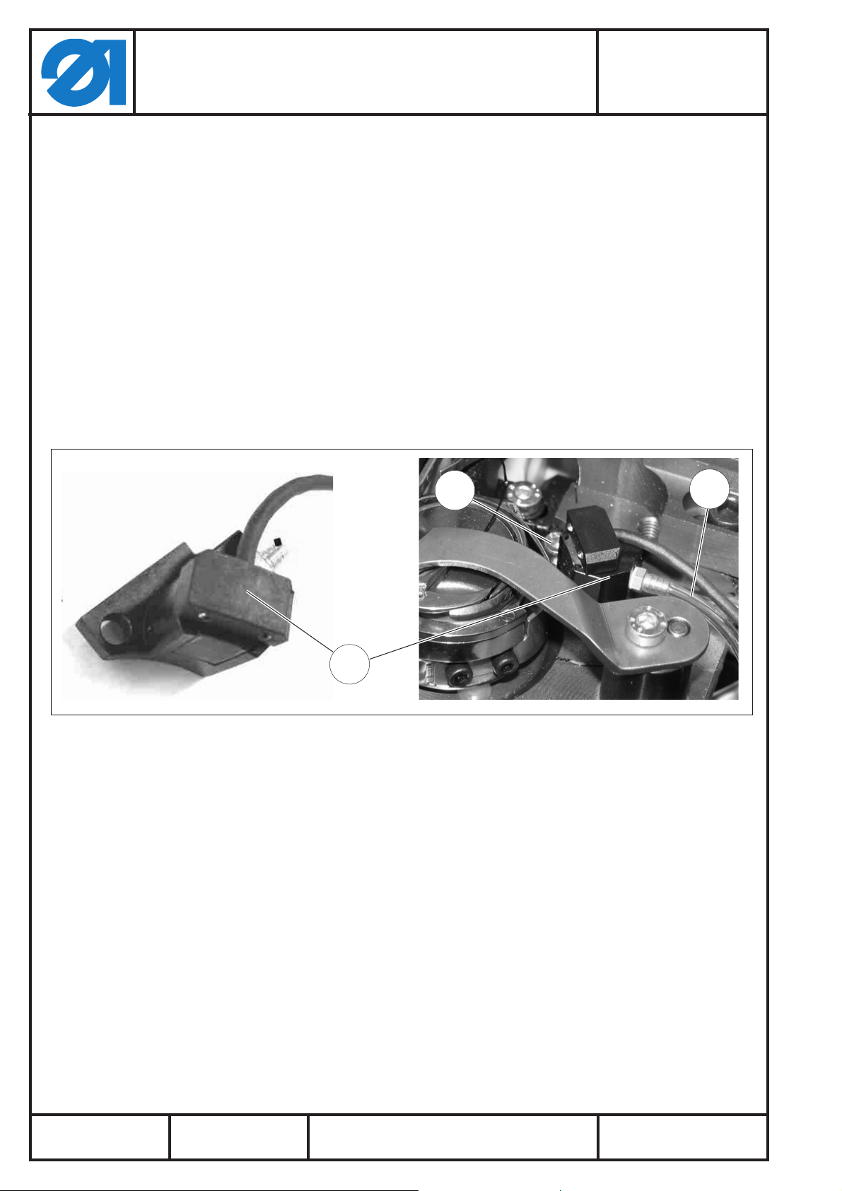
2 Restfadenwächter (RFW) montieren
2.1 Lichtschranke montieren
Mit der Schraube 1 den vormontierten Träger 2 anschrauben.
–
Position der Lichtschranke so einstellen, dass deren Lichtstrahl
–
durch den Schlitz der Spulenkapsel auf die Reflexionsfläche
der Spule und wieder zurück zur Lichtschranke gelangen kann.
Hinweis:
In der Regel muss die Vorderkante der Lichtschranke parallel zur
Vorderkante des Trägers 2 montiert werden.
Schlauch 3 für den Bläser anschließen.
–
Teile-Nr./ Part-No.:
0791 911703
1
3
2
Ausgabe/Edition:
03.2011
Änderungsindex
Rev. index: 00.0
Printed in Germany
Blatt: von
Sheet: 2 from 20
Page 3
Anbauanleitung Restfadenwächter
Fitting Instruction for Remaining Thread Monitor
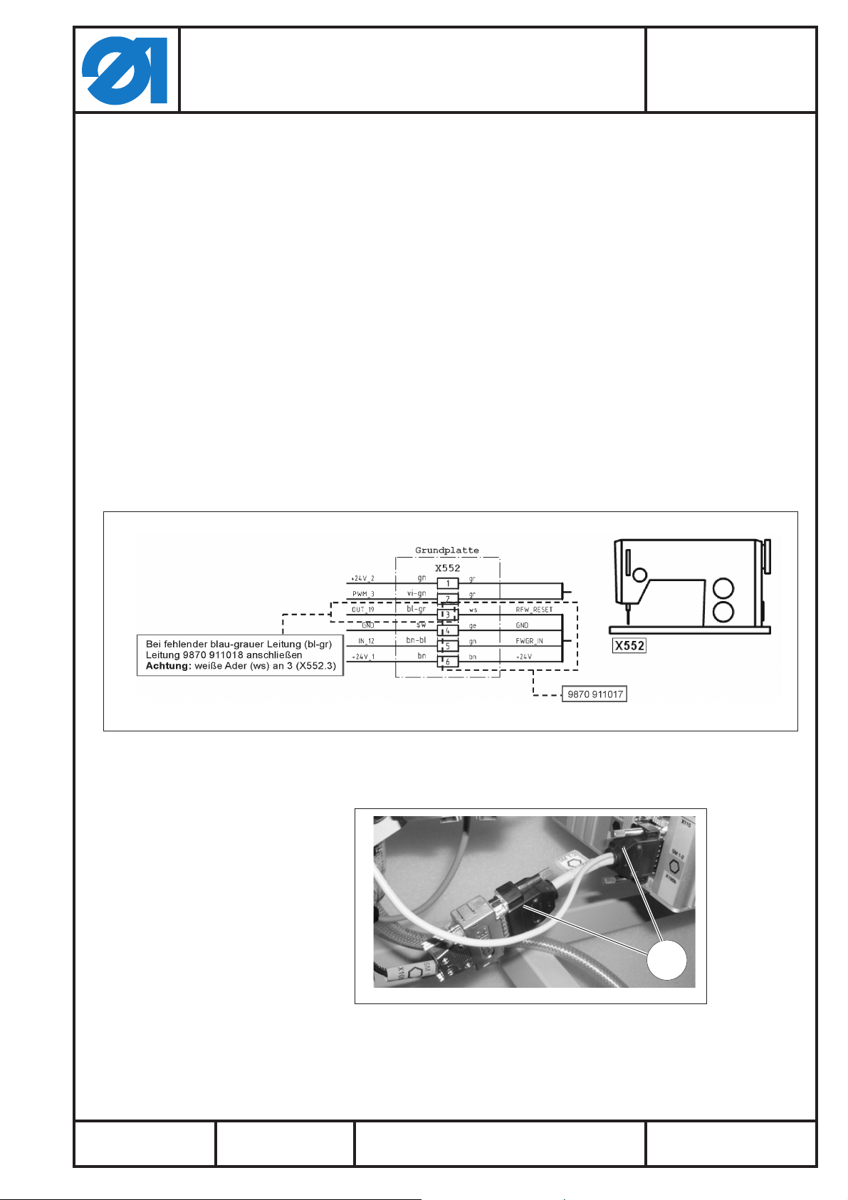
2.2 Leitungen verlegen
Teilesatz 0911 597754
Kit 0911 597754
Die Lichtschrankenleitung, die Leitung 9870 911017 (bis
–
Kabelbaum nach Änderungs-stand 9870 911003_02.0) und den
Luftschlauch durch die Bohrungen in der Grundplatte der
Maschine führen und mit Kabelbindern an dem vorhandenen
Strang (Elektroleitungen, Pneumatik- und Ölschläuche)
befestigen.
Die Leitungen rechts aus dem Arm zur rechten Konsole führen.
–
Den Luftschlauch links aus dem Arm zur linken Konsole führen.
–
Wenn Steckverbinder X632 an rechter Konsole nicht vorhanden
–
(bis Kabelbaum nach Änderungsstand 9870 911003_02.0):
Die Leitung 9870 911017 mit den Flachsteckern an der Klemme
X552 in der Grundplatte wie folgt anschließen (vergleiche auch
Anschlussplan 9890 911003 B):
ws an 3
ge an 4
gn an 5
bn an 6
Teile-Nr./ Part-No.:
0791 911703
Ausgabe/Edition:
03.2011
Änderungsindex
Rev. index: 00.0
–
Die Leitung 9870 911018 mit dem Adapter-Stecker 1 (X100b)
an die Steuerung anschließen.
1
Printed in Germany
Blatt: von
Sheet: 3 from 20
Page 4
Anbauanleitung Restfadenwächter
Teilesatz 0911 597754
Fitting Instruction for Remaining Thread Monitor
Kit 0911 597754
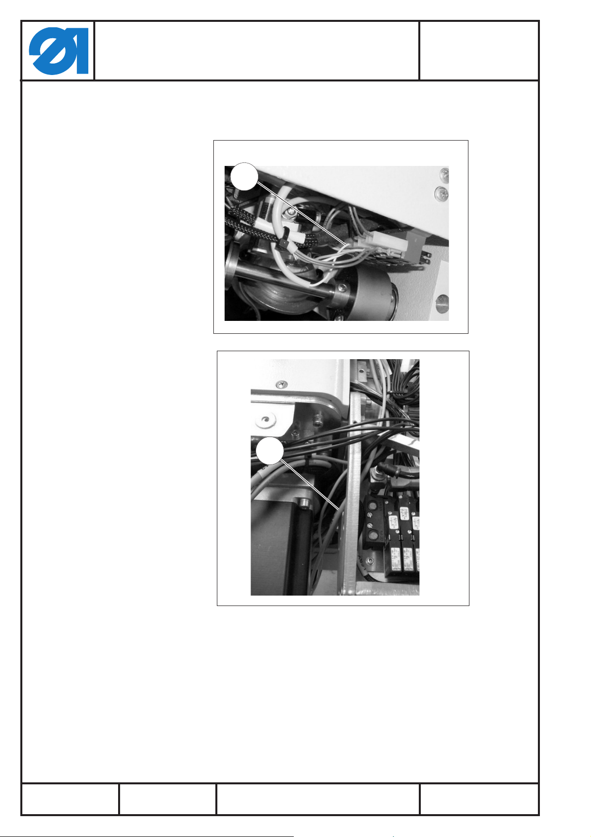
Die Leitung 3 über die linke Konsole durch den Ständer und die
–
Grundplatte der Maschine führen und die weiße Ader (ws) 2 an
X552.3 anschließen.
2
Teile-Nr./ Part-No.:
0791 911703
3
Ausgabe/Edition:
03.2011
Änderungsindex
Rev. index: 00.0
Printed in Germany
Blatt: von
Sheet: 4 from 20
Page 5
Anbauanleitung Restfadenwächter
Teilesatz 0911 597754
Fitting Instruction for Remaining Thread Monitor
Kit 0911 597754
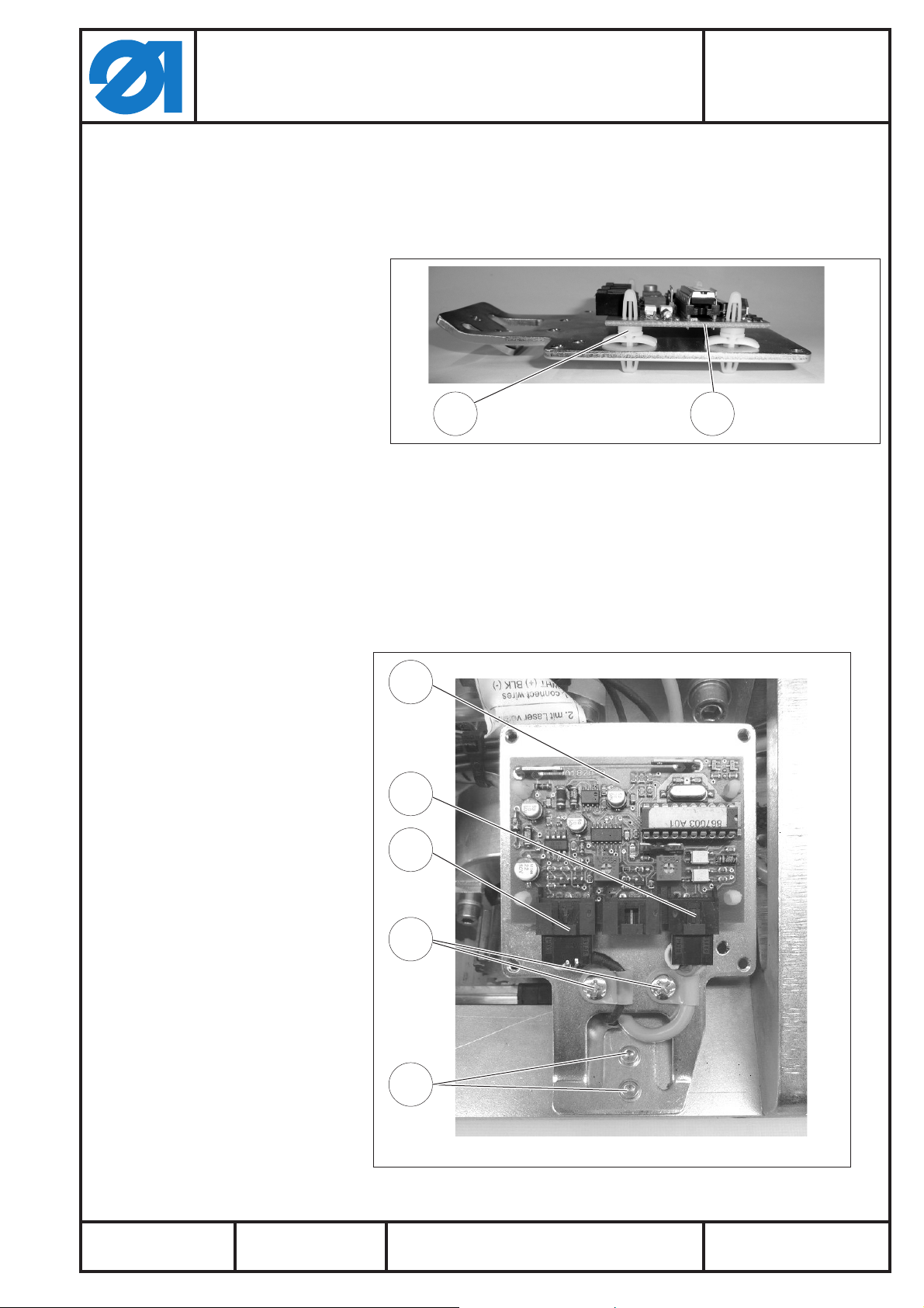
2.3 Steuerung vormontieren, verbinden und anschrauben
Distanzhalter 1 (4x) in die Bohrungen des RFW-Halters
–
einstecken und die Leiterplatte 2 aufstecken.
1 2
Teile-Nr./ Part-No.:
0791 911703
Die Leitungen an der RFW-Leiterplatte anschließen:
–
Steckverbinder X623 (von Kabelbaum oder Leitung
–
9870 911017) an Position 3 Steckverbinder X621 der
Lichtschrankenleitung an Position 4.
– Leitungen mit den Befestigungsschellen 5 an dem
RFW-Halter anschrauben.
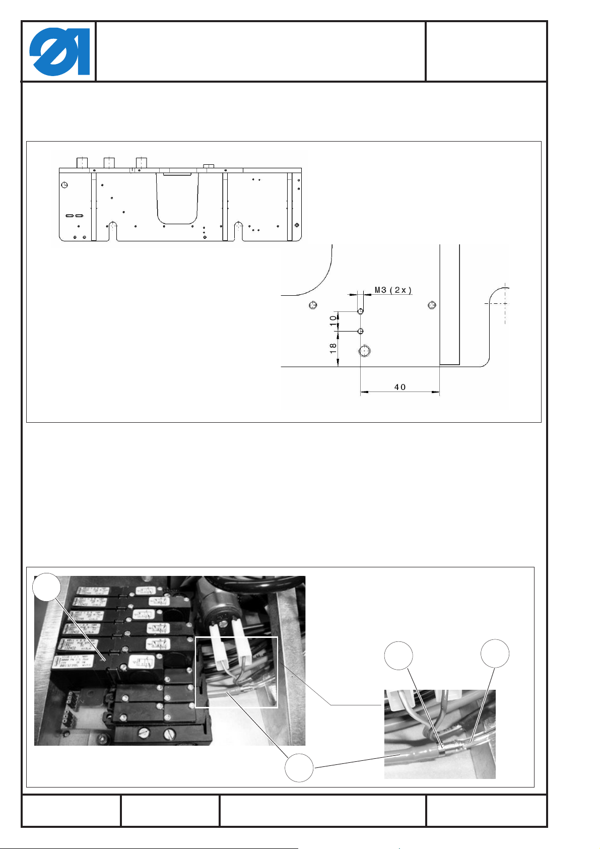
– RFW-Halter mit Leiterplatte mittels zwei M3 Schrauben 6
an die rechte Konsole schrauben.
2
3
4
5
Ausgabe/Edition:
03.2011
Änderungsindex
Rev. index: 00.0
6
Printed in Germany
Blatt: von
Sheet: 5 from 20
Page 6
Anbauanleitung Restfadenwächter
Teilesatz 0911 597754
Fitting Instruction for Remaining Thread Monitor
Kit 0911 597754
Achtung:
Evtl. müssen zwei M3 Gewindebohrungen in der Konsole
nachgearbeitet werden!
Teile-Nr./ Part-No.:
0791 911703
2.4 Ventil montieren und verbinden
– 3/2-Wege-Ventil 1 auf Position 6 der Ventileinheit montieren
(Blindplatte entfernen).
–
Den von der Lichtschranke zur linken Konsole geführten
Schlauch 2 mit dem Reduziernippel 3 verbinden; das
Schlauchstück 4 mit dem Reduziernippel und dem Ventilblock
(unterer Anschluss!) verbinden (eventuell vorhandene
Schläuche abziehen oder entfernen).
1
3
2
Ausgabe/Edition:
03.2011
Änderungsindex
Rev. index: 00.0
4
Printed in Germany
Blatt: von
Sheet: 6 from 20
Page 7

Anbauanleitung Restfadenwächter
Fitting Instruction for Remaining Thread Monitor
3 Bedienen
3.1 Spulenfaden aufspulen
Teile-Nr./ Part-No.:
Teilesatz 0911 597754
0791 911703
Kit 0911 597754
A
3.2 RFW aktivieren
Beim Aufspulen der RFW-Spulen muss die Rille A am Spuler
–
anliegen, sie ist somit nicht mehr sichtbar.
– Es muss in dem schmalen, hinteren Spulenbereich angewickelt
werden.
– Die Spule muss mit der Rille A nach unten in den Greifer
eingelegt werden!
(Siehe auch Bedienanleitung, Kap. 7.7.4: Maschinenparameter
bearbeiten).
–
Unter „Maschinenparameter“ „MP1 – Konfiguration“ anwählen.
–
Anschließend „Optionen“ (MP1.4) anwählen und
Restfadenwächter aktivieren.
Ausgabe/Edition:
03.2011
Änderungsindex
Rev. index: 00.0
Printed in Germany
Blatt: von
Sheet: 7 from 20
Page 8
Anbauanleitung Restfadenwächter
Teilesatz 0911 597754
Fitting Instruction for Remaining Thread Monitor
3.3 Bedien- und Funktionsfolge
Teile-Nr./ Part-No.:
0791 911703
Kit 0911 597754
Vorraussetzung:
Die Spule ist so in den Greifer eingesetzt, dass sich deren Rille A
unten befindet.
Nach der Erkennung: „Spule bis auf eine bestimmte
Restfadenmenge leer“:
Auf dem Bedienfeld erscheint: „Ereigniscode: 3220“
Die Frage „Nähvorgang fortsetzen“ muss mit „OK“ oder „Abbruch“
bestätigt werden.
Auswahl „OK“ (bei noch kurzen zu nähenden Strecken):
–
Das Nahtprogramm wir zu Ende geführt. Nach dem
Fadenabschneiden erscheinen folgende Meldungen auf dem
Bildschirm: „Leere Spule“ / „Volle Spule einlegen“
üblicher Spulenwechsel muss durchgeführt werden.
–
Auswahl „Abbruch“ (bei langen zu nähenden Strecken):
–
Fadenabschneiden wird durchgeführt; anschließend wechselt
die Steuerung in den Reparaturmodus.
üblicher Spulenwechsel muss durchgeführt werden.
–
– anschließend im Reparaturmodus die restliche Nahtstrecke zu
Ende führen.
Ausgabe/Edition:
03.2011
Änderungsindex
Rev. index: 00.0
Printed in Germany
Blatt: von
Sheet: 8 from 20
Page 9

Anbauanleitung Restfadenwächter
Teilesatz 0911 597754
Fitting Instruction for Remaining Thread Monitor
Kit 0911 597754
4 Elektrische Einstellung
4.1 Einstellung Restfadenwächter (RFW)
Der Restfadenwächter (RFW) wird mit einer Grundeinstellung
ausgeliefert.
In der Regel muss die Empfindlichkeit des RFW’s nicht eingestellt
werden!
Die voreingestellte Empfindlichkeit darf nur verändert werden,
wenn der RFW nicht einwandfrei arbeitet.
(Siehe Einstellung der Empfindlichkeit).
Anschlüsse:
Steckverbindung 2 (X1) = Lichtschranke (rechter) Greifer
Steckverbindung 4 (X3) = Aus- und Eingänge der
Teile-Nr./ Part-No.:
0791 911703
Nähantriebssteuerung.
1
3
2 4
Elektrische Einstellung des RFW’s / der Lichtschranke
Die mit dem Potentiometer 1 (R4) in der Steuerung eingestellte
Empfindlichkeit der Lichtschranke ist werksmäßig voreingestellt
und darf nur verändert werden, wenn der RFW nicht einwandfrei
arbeitet.
Einstellung der Empfindlichkeit
–
Empfindlichkeitseinstellung mit Potentiometer 1 (R4),
Steckverbindung 2.
–
Drehen im Uhrzeigersinn = höhere Empfindlichkeit,
–
entgegen dem Uhrzeigersinn = geringere Empfindlichkeit.
Ablauf der Empfindlichkeitseinstellung
–
Eine leere Spule in den Greifer einlegen und den Greifer so
stellen, dass die Lichtschranke durch den Schlitz im
Greifergehäuse freien Blick auf die Spule hat.
–
Das Potentiometer auf höchste Empfindlichkeit (drehen im
Uhrzeigersinn) einstellen und mit der Hand die Spule im Greifer
so lange drehen, bis die reflektierende Fläche gefunden ist. Die
Leuchtdiode 3 (V10) leuchtet und der Ausgang zur Steuerung
sowie der Zusatzausgang werden eingeschaltet.
–
Jetzt die Empfindlichkeit am Potentiometer 2 so weit
reduzieren, bis die Reflexion der Spule gerade noch erkannt
wird.
Ausgabe/Edition:
03.2011
Änderungsindex
Rev. index: 00.0
Hinweis:
Im Einstellmodus leuchtet die Leuchtdiode 3 (V10) bei jeder
Reflexion eine Sekunde.
Printed in Germany
Blatt: von
Sheet: 9 from 20
Page 10

Notizen:
Anbauanleitung Restfadenwächter
Teilesatz 0911 597754
Fitting Instruction for Remaining Thread Monitor
Kit 0911 597754
Teile-Nr./ Part-No.:
0791 911703
Ausgabe/Edition:
03.2011
Änderungsindex
Rev. index: 00.0
Printed in Germany
Blatt: von
Sheet: 10 from 20
Page 11

Anbauanleitung Restfadenwächter
Teilesatz 0911 597754
Fitting Instruction for Remaining Thread Monitor
1 Kit Components
The kit consists of the following components:
Quantity Designation Material-No
1 0667 155824 Residual thread monitor carrier
1 9202 002077 Cylinder head screw M4 x 10
0,9 m 0699 979265 Hose-PUR
1 9815 925002 Light barrier
1 9850 867003 PCB
1 0667 155840 Bracket
2 9204 201647 Fillister head screw M4 x 6
4 9830 501010 Spacer
2 9202 001667 Cylinder head screw M3 x 8
1 9790 000220 Adapter nipple
1 9710 061200 Solenoid valve
0,04 m 9731 005004 Tube
4 9840 121002 Cable tie
2 9840 120025 Cable clip
3 0867 150560 Bobbin
1 9870 911017 Cable
1 9870 911018 Cable
1 9890 911003 B Connection diagram
Teile-Nr./ Part-No.:
0791 911703
Kit 0911 597754
Caution: Risk of injury!
Turn off the main switch and unplug the mains lead before
performing the conversion task.
The fitting of the kit must be carried out by qualified technicians
only.
Ausgabe/Edition:
03.2011
Änderungsindex
Rev. index: 00.0
Printed in Germany
Blatt: von
Sheet: 11 from 20
Page 12

Anbauanleitung Restfadenwächter
Teilesatz 0911 597754
Fitting Instruction for Remaining Thread Monitor
Kit 0911 597754
2 Mounting the bobbin thread monitor (RFW)
2.1 Mounting the light barrier
Attach the pre-assembled carrier 2 by using screw 1.
–
Position the light barrier so that its light beam points through
–
the slit on the bobbin case onto the reflecting surface on the
bobbin and back to the light barrier.
Note:
In general the front edge of the light barrier device has to come
parallel with the front edge of the carrier 2.
Connect the hose 3 for the compressed air.
–
Teile-Nr./ Part-No.:
0791 911703
1
3
2
Ausgabe/Edition:
03.2011
Änderungsindex
Rev. index: 00.0
Printed in Germany
Blatt: von
Sheet: 12 from 20
Page 13

Anbauanleitung Restfadenwächter
Teilesatz 0911 597754
Fitting Instruction for Remaining Thread Monitor
Kit 0911 597754
2.2 Connecting the cables and hoses
Conduct the light barrier cable, the cable 9870 911017 (up to
–
the cable harness after modification status 9870 911003_2.0)
and the air hose through the bore on t he base plate and attach
them with cable binders to the existing harness (consisting of
cables, pneumatic and lubrification hoses).
Conduct the cables to the right out of the machine arm to the
–
console on the right.
Conduct the air hose to the left out of the machine arm to the
–
console on the left.
If there is no plug connector X632 on the right console (up to
–
the cable harness after modification status 9870 911003_02.0):
Connect the cable 9870 911017 with the flat plugs onto the
clamp X552 on the base plate as follows (also compare
connection diagram 9890 911003 B):
white to 3
yellow to 4
green to 5
brown to 6
Teile-Nr./ Part-No.:
0791 911703
Ausgabe/Edition:
03.2011
Änderungsindex
Rev. index: 00.0
–
Connect the cable 9870 911018 with the adapter plug 1
(X100b) to the control unit.
1
Printed in Germany
Blatt: von
Sheet: 13 from 20
Page 14

Anbauanleitung Restfadenwächter
Teilesatz 0911 597754
Fitting Instruction for Remaining Thread Monitor
Kit 0911 597754
Conduct the cable 3 over the left console through the column
–
and the base plate of the machine and connect the white core 2
to X552.3.
2
Teile-Nr./ Part-No.:
0791 911703
3
Ausgabe/Edition:
03.2011
Änderungsindex
Rev. index: 00.0
Printed in Germany
Blatt: von
Sheet: 14 from 20
Page 15

Anbauanleitung Restfadenwächter
Teilesatz 0911 597754
Fitting Instruction for Remaining Thread Monitor
Kit 0911 597754
2.3 Pre-assembling, connecting and attaching the control
Insert the spacers 1 (4x) into the bores of the residual thread
–
monitor carrier and attach the PCB 2.
1 2
Teile-Nr./ Part-No.:
0791 911703
Connect the cables onto the residual thread monitor PCB:
–
Plug connector X623 (from the cable harness or cable 9870
–
911017) to position 3; plug connector X621 of the light
barrier cable to position 4.
– Attach the cables with the cable clips 5 to the residual
thread monitor carrier.
– Screw the residual thread monitor carrier with PCB onto
the right console by using two M3 screws 6.
2
3
4
5
Ausgabe/Edition:
03.2011
Änderungsindex
Rev. index: 00.0
6
Printed in Germany
Blatt: von
Sheet: 15 from 20
Page 16

Anbauanleitung Restfadenwächter
Teilesatz 0911 597754
Fitting Instruction for Remaining Thread Monitor
Kit 0911 597754
Attention:
You may have to tap two M3 threads into the console!
Teile-Nr./ Part-No.:
0791 911703
2.4 Assembling and connecting the valve
– Mount the 3-port/2-way valve 1 onto position 6 of the valve unit
(remove t he dummy plate).
–
Connect the hose 2 that has been conducted to the left
console with the adapter nipple 3; connect the hose 4 with the
adapter nipple and the valve block (bottom plug!), if necessary
remove any existing hoses.
1
3
2
Ausgabe/Edition:
03.2011
Änderungsindex
Rev. index: 00.0
4
Printed in Germany
Blatt: von
Sheet: 16 from 20
Page 17

Anbauanleitung Restfadenwächter
Teilesatz 0911 597754
Fitting Instruction for Remaining Thread Monitor
Kit 0911 597754
3 Operating
3.1 Winding on the bobbin thread
Teile-Nr./ Part-No.:
0791 911703
A
The residual tread monitor bobbins have to be inserted for
–
winding on with the groove A pointing towards the winder, so
that the groove A is not visible.
– The thread has to be wound on into the small bobbin segment
first.
– The bobbin has to be inserted in the hook with the groove A
pointing downwards!
3.2 Activating the residual thread monitor
(Also see the operating manual chapter 7.7.4: Edit the machine
parameters)
–
Select “MP1 – Configuration” in “Machine parameters”.
–
Then select “Options” (MP1.4) and activate the bobbin thread
monitor.
Ausgabe/Edition:
03.2011
Änderungsindex
Rev. index: 00.0
Printed in Germany
Blatt: von
Sheet: 17 from 20
Page 18

Anbauanleitung Restfadenwächter
Teilesatz 0911 597754
Fitting Instruction for Remaining Thread Monitor
Kit 0911 597754
3.3 Operating and function sequence
Prerequisite:
The bobbin has to be inserted in the hook with the groove A
pointing downwards.
After the detection: “Bobbin almost empty, only certain residual
thread left”:
The control panel will display the follwing: “Event code: 3220"
The request “Continue sewing” has to be confirmed with either
“OK” or “Cancel”.
Selection “OK” (with a short segment to be sewn left):
–
The sewing program will be completed. After the thread
trimming the following message will appear on the display:
“Bobbin empty” / “Insert a full bobbin”
The regular bobbin change has to be carried out.
–
Teile-Nr./ Part-No.:
0791 911703
Selection “Cancel” (with long segments left to be sewn):
–
Thread trimming will occur; afterwards the control changes to
the repair mode.
– The regular bobbin change has to be carried out.
– Afterwards finish the seam segment left in repair mode.
Ausgabe/Edition:
03.2011
Änderungsindex
Rev. index: 00.0
Printed in Germany
Blatt: von
Sheet: 18 from 20
Page 19

Anbauanleitung Restfadenwächter
Teilesatz 0911 597754
Fitting Instruction for Remaining Thread Monitor
Kit 0911 597754
4 Electrical setting
4.1 Setting bobbin thread monitor
The residual thread monitor is delivered with a basic factory
setting.
Normally the sensitivity of the residual thread monitor must not be
readjusted!
The preset sensitivity should only be adjusted if the residual thread
monitor does not function properly.
(See Setting the sensitivity).
Connections:
Plug connection 2 (X1) = Light barrier hook (to the right)
Plug connection 4 (X3) = Input and output of the sewing drive
control.
Teile-Nr./ Part-No.:
0791 911703
1
3
2 4
Electrical setting of the residual thread monitor / the light
barrier
The light barrier’s sensitivity factory presetting via the
potentiometer 1 (R4) in the control may only be altered if the
residual thread monitor does not function properly.
Setting the sensitivity
–
Setting the sensitivity with the potentiometer 1 (R4), plug
connection 2.
–
Turning clockwise = higher sensitivity,
–
counter-clockwise = lower sensitivity.
Operation of the sensitivity setting
–
Insert an empty bobbin into the hook and position the hook so
that the light barrier can point unimpededly through the slit in
the hook case to the bobbin.
–
Set the potentiometer to the highest sensitivity (by turning it
clockwise) and turn the bobbin in the hook until the reflecting
surface appears. The LED 3 (V10) lights up and the output to
the control as well as the additional output are switched on.
–
Now reduce t he sensitivity on the potentiometer 2 until the
reflection on the bobbin is still just recognized.
Ausgabe/Edition:
03.2011
Änderungsindex
Rev. index: 00.0
Note:
In the setting mode the LED 3 (V10) lights up for one second at
each reflection.
Printed in Germany
Blatt: von
Sheet: 19 from 20
Page 20

Notes:
Anbauanleitung Restfadenwächter
Teilesatz 0911 597754
Fitting Instruction for Remaining Thread Monitor
Kit 0911 597754
Teile-Nr./ Part-No.:
0791 911703
Ausgabe/Edition:
03.2011
Änderungsindex
Rev. index: 00.0
Printed in Germany
Blatt: von
Sheet: 20 from 20
 Loading...