

Duerkopp Adler 911 Service Manual

911
CNC-controlled sewing unit with large
sewing area
Operating Instructions
Installation Instructions
Service Instructions
1
2
3
Postfach 17 03 51, D-33703 Bielefeld Potsdamer Straße 190, D-33719 Bielefeld
Telefon +49 (0) 5 21/ 59 25-00 Telefax +49 (0) 5 21/ 9 25 24 35 www.duerkopp-adler.com
Ausgabe / Edition: Änderungsindex Teile-Nr./Part.-No.:
08/2010 Rev. index: 00.0 Printed in Federal Republic of Germany 0791 911001

All rights reser ved.
Property of Dürkopp Adler AG and copyrighted. Reproduction or publication of the content in any
manner, even in extracts, without prior written permission of Dürkopp Adler AG, is prohibited.
Copyright ©
Dürkopp Adler AG - 2010

Foreword
This instruction manual is intended to help the user to become familiar
with the machine and take advantage of its application possibilities in
accordance with the recommendations.
The instruction manual contains important information on how to
operate the machine securely, properly and economically. Observation
of the instructions eliminates danger, reduces costs for repair and
down-times, and increases the reliability and life of the machine.
The instruction manual is intended to complement existing national
accident prevention and environment protection regulations.
The instruction manual must always be available at the machine/sewing
unit.
The instruction manual must be read and applied by any person that is
authorized to work on the machine/sewing unit. This means:
– Operation, including equipping, troubleshooting during the work
cycle, removing of fabric waste,
– Service (maintenance, inspection, repair) and/or
– Transport.
The user also has to assure that only authorized personnel work on the
machine.
The user is obliged to check the machine at least once per shift for
apparent damages and to immediatly report any changes (including the
performance in service), which impair the safety.
The user company must ensure that the machine is only operated in
perfect working order.
Never remove or disable any safety devices.
If safety devices need to be removed for equipping, repairing or
maintaining, the safety devices must be remounted directly after
completion of the maintenance and repair work.
Unauthorized modification of the machine rules out liability of the
manufacturer for damage resulting from this.
Observe all safety and danger recommendations on the machine/unit!
The yellow-and-black striped surfaces designate permanend danger
areas, eg danger of squashing, cutting, shearing or collision.
Besides the recommendations in this instruction manual also observe
the general safety and accident prevention regulations!

General safety instructions
The non-observance of the following safety instructions can cause
bodily injuries or damages to the machine.
1. The machine must only be commissioned in full knowledge of the
2. Before putting into service also read the safety rules and
3. The machine must be used only for the purpose intended. Use of
4. When gauge parts are exchanged (e.g. needle, presser foot, needle
5. Daily servicing work must be carried out only by appropriately
instruction book and operated by persons with appropriate training.
instructions of the motor supplier.
the machine without the safety devices is not permitted. Observe all
the relevant safety regulations.
plate, feed dog and bobbin) when threading, when the workplace is
left, and during service work, the machine must be disconnected
from the mains by switching off the master switch or disconnecting
the mains plug.
trained persons.
6. Repairs, conversion and special maintenance work must only be
carried out by technicians or persons with appropriate training.
7. For service or repair work on pneumatic systems, disconnect the
machine from the compressed air supply system (max. 7-10 bar).
Before disconnecting, reduce the pressure of the maintenance unit.
Exceptions to this are only adjustments and functions checks made
by appropriately trained technicians.
8. Work on the electrical equipment must be carried out only by
electricians or appropriately trained persons.
9. Work on parts and systems under electric current is not permitted,
except as specified in regulations DIN VDE 0105.
10. Conversion or changes to the machine must be authorized by us
and made only in adherence to all safety regulations.
11. For repairs, only replacement parts approved by us must be used.
12. Commissioning of the sewing head is prohibited until such time as
the entire sewing unit is found to comply with EC directives.
13. The line cord should be equipped with a country-specific mains
plug. This work must be carried out by appropriately trained
technicians (see paragraph 8).
It is absolutely necessary to respect the safety
instructions marked by these signs.
Danger of bodily injuries !
Please note also the general safety instructions.

Contents Page:
Part 3: Service instructions class 911
(Edition 08/2010)
1. General information
1.1 Gauges..................................................... 4
1.2 Descriptionofthemarkingpositions................................... 4
2. Sewing machine, top
2.1 Positionoftheneedlebarcrankonthearmshaft........................... 5
2.2 Position of the top sprocket belt wheel ................................. 6
2.3 Position bottom sprocket belt wheel ................................... 7
2.4. Aligningneedlebarcrank.......................................... 8
2.5 Hook,loopstrokeandneedlebarheight ................................ 9
2.5.1 Loop stroke .................................................. 9
2.5.2 Needlebarheight .............................................. 10
2.5.3 Distance between hook and needle.................................... 11
2.5.4 Needle guard at the hook .......................................... 12
2.5.5 Needleguide ................................................. 13
2.6 Bobbin housing elevator .......................................... 14
2.6.1 General..................................................... 14
2.6.2 Bobbin housing elevator path ....................................... 14
2.6.3 Elevationtime................................................. 16
2.7 Sewingfootelevation............................................ 17
2.7.1 Checking the lift position drive ...................................... 17
2.7.2 Settingthelightbarrier........................................... 18
2.7.3 Settingtheleftstopscrewoftheliftdrive................................ 19
2.7.4 Setting the foot lift according to the needle bar lift .......................... 20
2.7.5 Foot height .................................................. 22
2.7.6 Referencelightbarriersewingaxis.................................... 24
2.8 Threadguidingparts............................................. 25
2.8.1 Threadregulator............................................... 25
2.8.2 Threadtakeupspring............................................ 26
2.9 Shortthreadcutter.............................................. 28
2.9.1 General..................................................... 28
2.9.2 Lockingcatchforthreaddrawcutter................................... 29
2.9.3 Threaddrawcutter.............................................. 30
2.9.4 Counter cutter ................................................ 32
2.9.5 Cuttingposition................................................ 34
3
3. Oil lubrication
3.1 Hooklubrication ............................................... 36
4. Maintenance ................................................. 37

1. General
These service instructions describe how to set up the special CNC
controlled large field 911 sewing unit.
IMPORTANT!
The tasks described in these service instructions must only be carried
out by qualified or appropriately t rained people.
Caution: Danger of injury!
Turn off the main switch for repair, conversion and maintenance work
and disconnect the machine from the pneumatic supply system.
Only carry out adjustment work and function tests when the machine
is running with the greatest care and observing all safety measures.
These service instructions describe how to set the sewing unit up in a
practical order. With this it must be noted that different setting
positions depend on each other. Therefore, perform the settings in the
order described.
A new, perfect needle must be used for all adjustment work on stitch
creating parts.
Machine covers that must be unscrewed and screwed back on again
for inspection and adjustment work are not mentioned in the text.
3
Important
On the 911 sewing unit some shafts have flat spots that make it
considerably easier to adjust the machine.
For all adjustments on the flat spot each time the first screw is
screwedinthedirectionofrotationontheflatspot.
The hand wheel is replaced by crank 1 on the arm cover to turn the
machine into the different setting positions.
1
3
1.1 Gauges
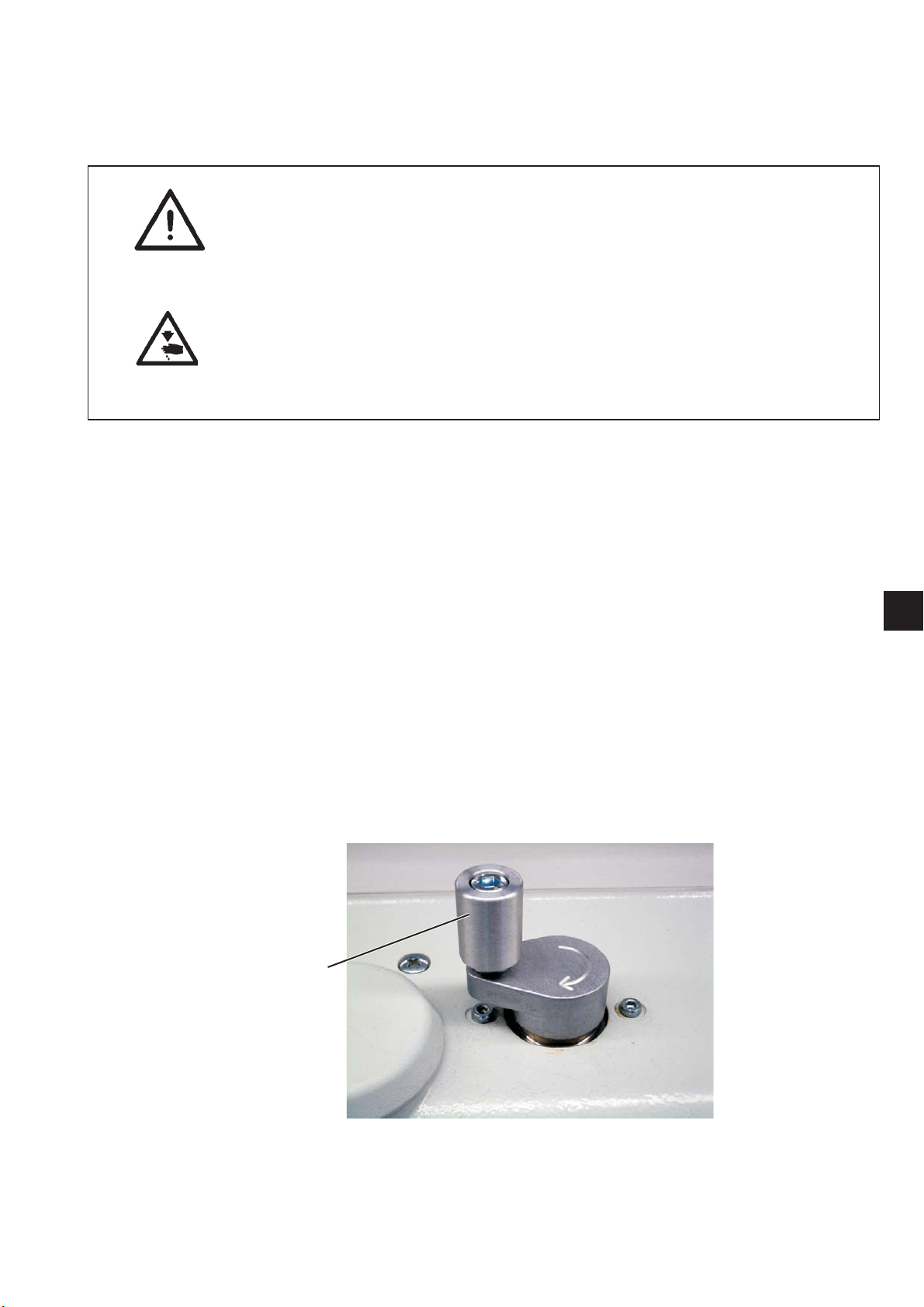
The locking pin 1 required to set the sewing unit is provided as
standard with the machine. It is included with the machine
1.2 Description of the marking positions
1
3
4
2
1
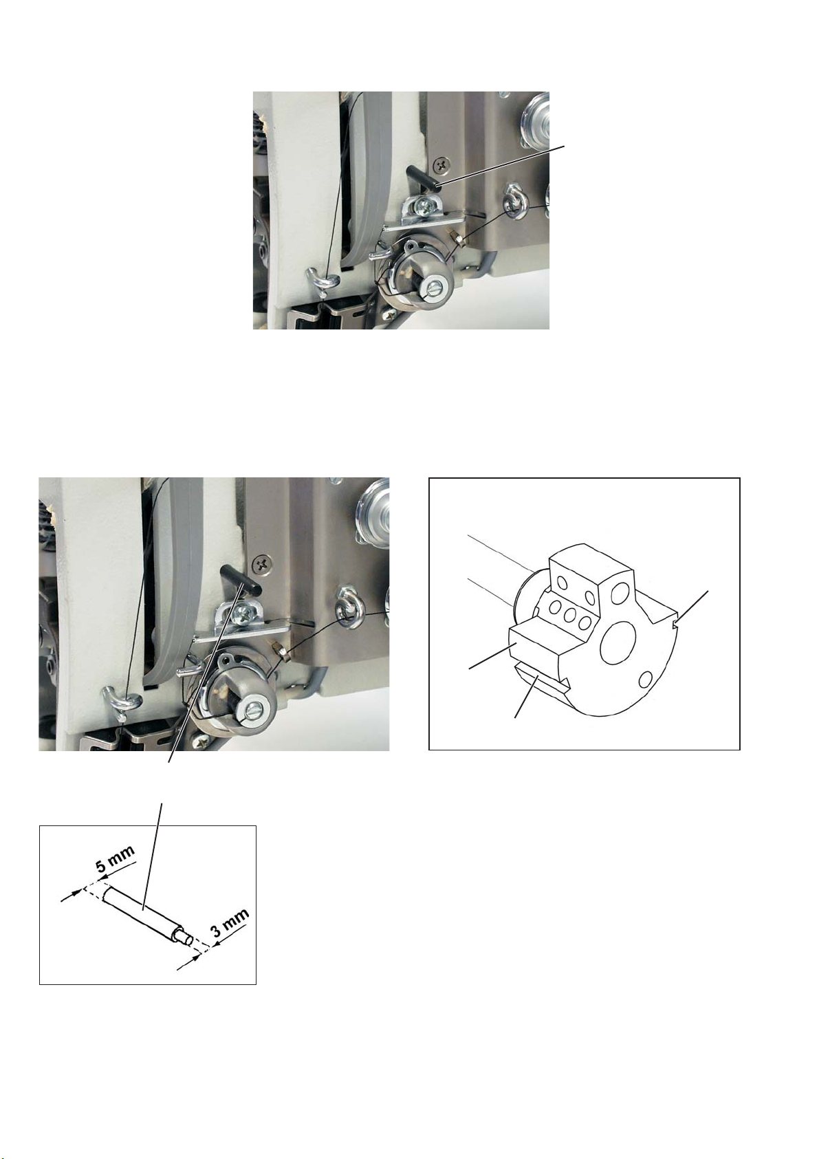
With the locking pin 1, the sewing machine can be locked in two
setting positions in the marking grooves 2 and 3 in the needle bar
crank 4.
Position I = Ø 5 mm locking pin for large groove
= loop stroke, needle bar height
Position II = Ø 3 mm locking pin for small groove
= needle bar at top dead centre
4
2. Upper part of sewing machine
2.1 Position of the needle bar crank on the arm shaft
21
2
4
3
1
Caution: Danger of injury!
Turn off the main switch.
Only check and adjust the position of the needle bar crank when the
sewing unit is switched off.
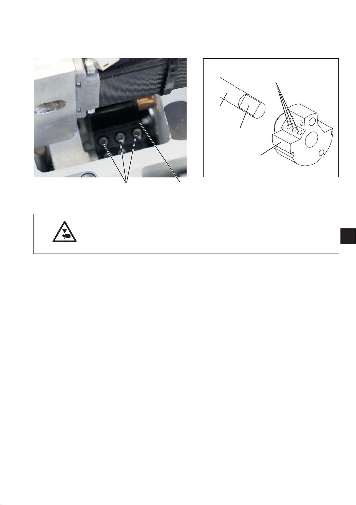
Adjustment and inspection
The needle bar crank 1 is fixed to the arm shaft with the two screws 2.
The screws must be seated on the flat spot 3.
To a dju st
–
Undo grub screws 2 on the needle bar crank.
–
Turn the needle bar crank on the shaft so that the screws 2 are
seated on the flat spot 3.
–
Push the needle bar crank axially to the right until it will go no
further.
–
Screwupgrubscrew2.
3
5
2.2 Position of the top sprocket belt wheel
43 2 1
Caution: Danger of injury!
Turn off the main switch.
Only check and adjust the position of the top sprocket belt wheel
when the sewing unit is switched off.
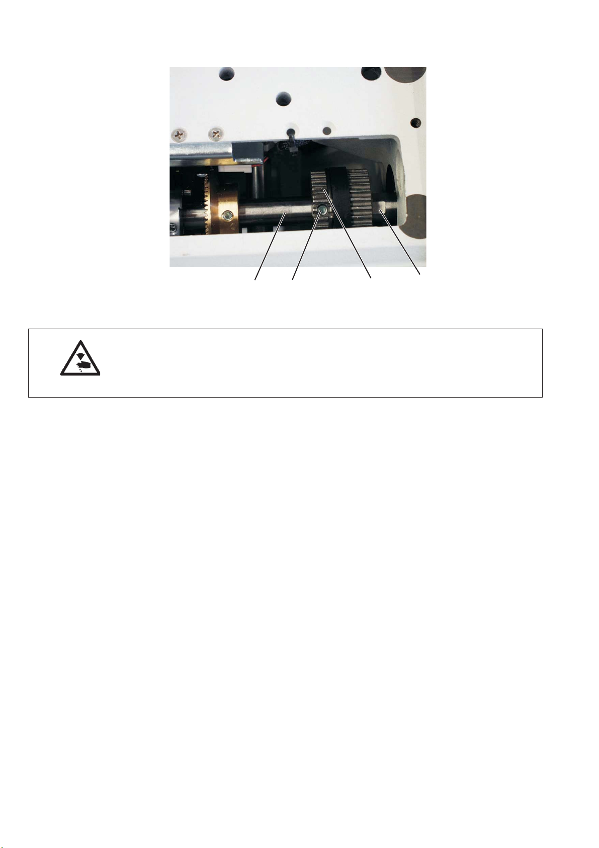
Adjustment and inspection
The sprocket belt wheel 2 is fitted to the arm s haft 4 with two grub
screws 3. The screws must be seated on the flat spot 1.
To a dju st
–
Undo the grub screws 3 on the sprocket belt wheel.
–
Turn the sprocket belt wheel until the grub screws sit on the flat
spot 1 of the arm shaft 4.
–
Screw up the grub screws 3 on the sprocket belt wheel.
6
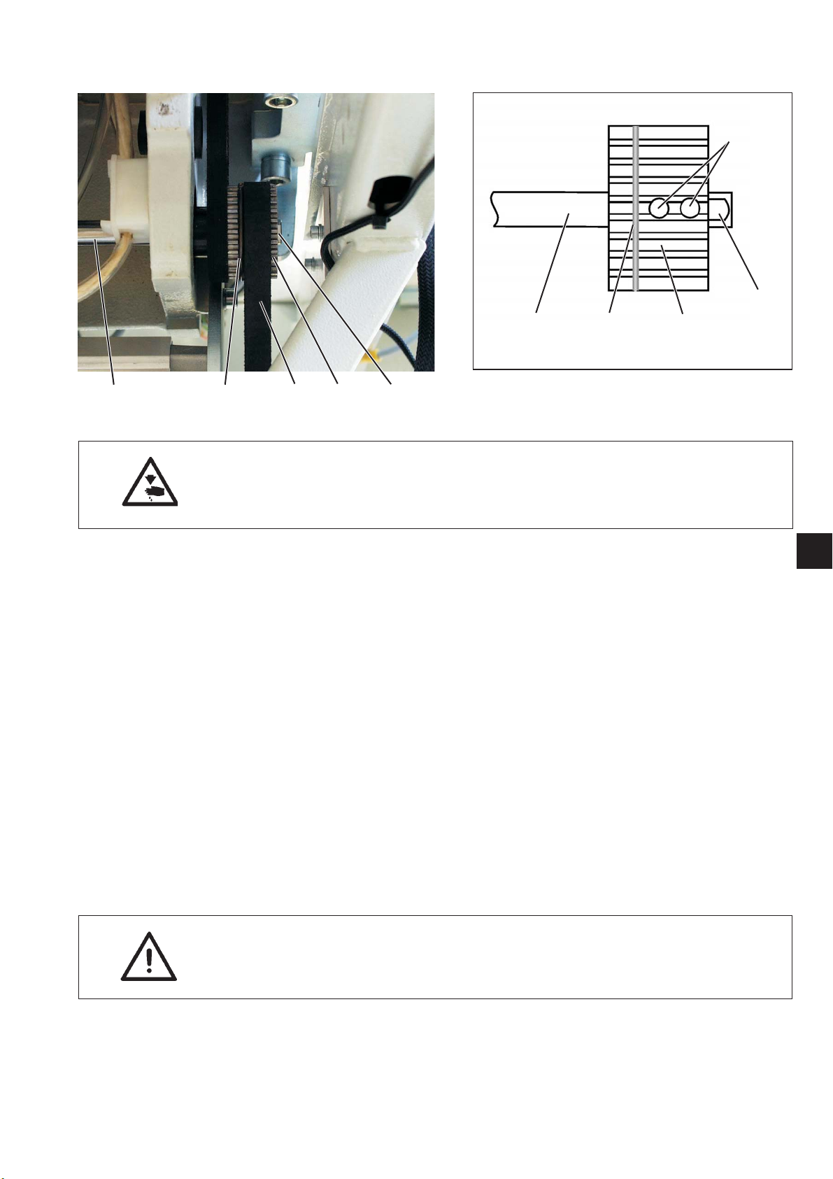
2.3 Position bottom sprocket belt wheel
6
1
54321
Caution: Danger of injury!
Turn off the main switch.
Only check and adjust the position of the lower sprocket belt wheel
when the sewing unit is switched off.
Adjustment and inspection
The grub screws in the sprocket belt wheel 2 must sit on the flat
spot 1 of the arm shaft 5.
The sprocket belt wheel must be in such a position that the sprocket
belt 3 touches the tensioning ring 4 but is not pushed aside when the
hand wheel is tur ned.
–
Check position of the s procket belt wheel
To a dju st
–
Remove the sprocket belt 3 from the bottom sprocket belt
wheel 2.
–
Undo the grub screws 6 on the sprocket belt wheel 2.
–
Turn the sprocket belt wheel until the grub screws sit on the flat
spot 1 of the lower shaft 5.
–
Screw up the grub screws on the sprocket belt wheel 2.
–
Reattach the sprocket belt 3 to the sprocket belt wheel 2.
–
Check the run on the sprocket belt 3.
45
2
3
CAUTION Risk of breaking!
Check hook position (see Chapter 2.5)
after sprocket belt change.
7
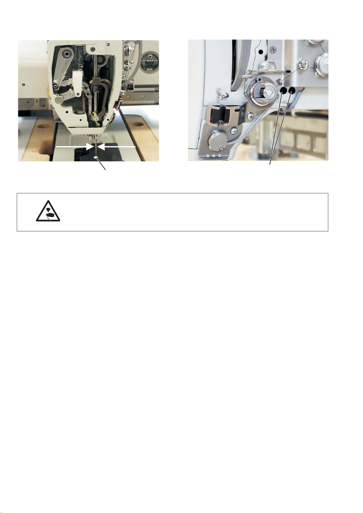
2.4. Aligning needle bar crank
1
Caution: Danger of injury!
Turn off the main switch.
Only check and adjust the needle bar crank when the sewing unit is
switched off.
Adjustment and inspection
The needle must go through the middle of the needle hole 1.
–
Fit a new needle.
–
Turn down needle bar.
–
Check the lateral position of the needle in the needle hole.
To a dju st
–
Undo both screws 2.
–
Set the needle bar crank so that the needle is in the middle of the
needle hole.
–
Screw up screws 2.
2
8
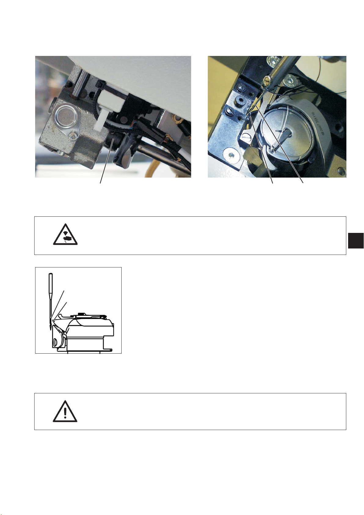
2.5 Hook, loop stroke and needle bar height
2.5.1 Loop stroke
3 21
Caution: Danger of injury!
Turn off the main switch.
Only check and adjust the loop stroke when the sewing unit is
switched off.
1
2
Adjustment and inspection
The loop stroke is the path of the needle bar from the top dead centre
to the point at which the hook tip 2 is in the middle of needle 1.
The loop stroke is 2 mm.
–
Locate top part of the machine in position I
(Ø 5 mm locking pin in the large groove).
–
Check the position of the hook tip in relation to the needle.
To a dju st
–
Locate the top part of the machine in position I
with the Ø 5 mm locking pin (large groove).
–
Undo the grub screws on the adjustment ring 3.
–
Turn the hook so that the hook tip 2 is in the middle of needle 1.
–
Screw up the grub screws on the adjustment ring 3.
3
CAUTION Risk of breaking!
After adjusting the hook, t he position of the thread cutter curve must
be checked (see Chapter 2.9.5).
9
 Loading...