


887
Spezialnähmaschine
Betriebsanleitung
Instruction manual
D
GB
Postfach 17 03 51, D-33703 Bielefeld • Potsdamer Straße 190, D-33719 Bielefeld
Telefon +49 (0) 521 / 9 25-00 • Telefax +49 (0) 521 / 9 25 24 35 • www.duerkopp-adler.com
Ausgabe / Edition: Änderungsindex Teile-Nr./Part.-No.:
06/2008 Rev. index: 00.0 Printed in Federal Republic of Germany 0791 887740

Alle Rechte vorbehalten.
Eigentum der Dürkopp Adler AG und urheberrechtlich geschützt. Jede, auch auszugsweise Wiederverwendung
dieser Inhalte ist ohne vorheriges schriftliches Einverständnis der Dürkopp Adler AG verboten.
All rights reserved.
Property of Dürkopp Adler AG and copyrighted. Reproduction or publication of the content in any manner, even
in extracts, without prior written permission of Dürkopp Adler AG, is prohibited.
Copyright ©
Dürkopp Adler AG - 2008

Foreword
This instruction manual is intended to help the user to become familiar
with the machine and take advantage of its application possibilities in
accordance with the recommendations.
The instruction manual contains important information on how to
operate the machine securely, properly and economically. Observation
of the instructions eliminates danger, reduces costs for repair and
down-times, and increases the reliability and life of the machine.
The instruction manual is intended to complement existing national
accident prevention and environment protection regulations.
The instruction manual must always be available at the machine/sewing
unit.
The instruction manual must be read and applied by any person that is
authorized to work on the machine/sewing unit. This means:
– Operation, including equipping, troubleshooting during the work
cycle, removing of fabric waste,
– Service (maintenance, inspection, repair) and/or
– Transport.
The user also has to assure that only authorized personnel work on the
machine.
The user is obliged to check the machine at least once per shift for
apparent damages and to immediatly report any changes (including the
performance in service), which impair the safety.
The user company must ensure that the machine is only operated in
perfect working order.
Never remove or disable any safety devices.
If safety devices need to be removed for equipping, repairing or
maintaining, the safety devices must be remounted directly after
completion of the maintenance and repair work.
Unauthorized modification of the machine rules out liability of the
manufacturer for damage resulting from this.
Observe all safety and danger recommendations on the machine/unit!
The yellow-and-black striped surfaces designate permanend danger
areas, eg danger of squashing, cutting, shearing or collision.
Besides the recommendations in this instruction manual also observe
the general safety and accident prevention regulations!

General safety instructions
The non-observance of the following safety instructions can cause
bodily injuries or damages to the machine.
1. The machine must only be commissioned in full knowledge of the
2. Before putting into service also read the safety rules and
3. The machine must be used only for the purpose intended. Use of
4. When gauge parts are exchanged (e.g. needle, presser foot, needle
5. Daily servicing work must be carried out only by appropriately
instruction book and operated by persons with appropriate training.
instructions of the motor supplier.
the machine without the safety devices is not permitted. Observe all
the relevant safety regulations.
plate, feed dog and bobbin) when threading, when the workplace is
left, and during service work, the machine must be disconnected
from the mains by switching off the master switch or disconnecting
the mains plug.
trained persons.
6. Repairs, conversion and special maintenance work must only be
carried out by technicians or persons with appropriate training.
7. For service or repair work on pneumatic systems, disconnect the
machine from the compressed air supply system (max. 7-10 bar).
Before disconnecting, reduce the pressure of the maintenance unit.
Exceptions to this are only adjustments and functions checks made
by appropriately trained technicians.
8. Work on the electrical equipment must be carried out only by
electricians or appropriately trained persons.
9. Work on parts and systems under electric current is not permitted,
except as specified in regulations DIN VDE 0105.
10. Conversion or changes to the machine must be authorized by us
and made only in adherence to all safety regulations.
11. For repairs, only replacement parts approved by us must be used.
12. Commissioning of the sewing head is prohibited until such time as
the entire sewing unit is found to comply with EC directives.
13. The line cord should be equipped with a country-specific mains
plug. This work must be carried out by appropriately trained
technicians (see paragraph 8).
It is absolutely necessary to respect the safety
instructions marked by these signs.
Danger of bodily injuries !
Please note also the general safety instructions.

Contents Page:
Preface and general safety instructions
Part 1: Operating Instructions Class 887
(Edition 06/2008)
1. Product description ............................................ 5
2. Designated use ............................................... 5
3. Subclasses and sewing equipment
3.1 Subclasses .................................................. 6
3.2 Sewing equipment .............................................. 6
4. Optional equipment............................................. 7
5. Technical data ................................................ 8
6. Machine operation
6.1 Threading the needle thread ........................................ 9
6.2 Winding the hook thread .......................................... 9
6.3 Inserting the bobbin and threading the hook thread .......................... 10
6.4 Adjustingthethreadtension........................................ 11
6.4.1 Adjusting the hook thread tension ..................................... 11
6.4.2 Adjusting the needle thread tension .................................... 12
6.5 Switching the thread tensioner on/off ................................... 13
6.6 Adjusting the thread regulator ....................................... 14
6.7 Needle change ................................................ 15
6.8 Liftingandfoldingtherollerpresser.................................... 16
6.9 Sewing-footpressure ............................................ 17
6.10 Reversesewing(Backtacking)....................................... 18
6.11 Setting the stitch length ........................................... 19
6.12 Starting up the manually controlled machine with a clutch motor .................. 19
6.13 Controlling the machine equipped with a positioning motor ...................... 20
6.13.1 By a control pedal .............................................. 20
6.13.2 By a key panel ................................................ 21
GB
7. Positioning motor Efka DC1600/DA82GA
7.1 General ..................................................... 22
8. Positioning motor (drive) Efka VD552/6F82FA
8.1 General ..................................................... 22
9. Positioning drive Efka DC1550/DA321G
9.1 General ..................................................... 23

Contents Page:
10. Sewing w ith machine w ith positioning motor (drive)
10.1 Machineautomaticfunctions........................................ 24
10.2 Example of machine operation at sewing ................................ 25
11. Maintenance
11.1 Cleaning and checking ........................................... 26
11.2 Lubrication ................................................... 29

1. Product description
Dürkopp Adler 887 is a special sewing machine for universal use.
It is a flatbed double-lockstitch machine.
•
The machine has a double intermittent feeding. A lower wheel
•
feeder and a driven r oller presser feed in two steps, a needle feed
feeds in the first step only. The first step represents 50% of the total
stitch length.
Depending on subclass, the machine may be equipped with a large
•
or oversized hook, with automatic functions such as thread
trimming, automatic backtacking, automatic foot lifting.
Equipped with a two-piece vertical hook.
•
With a maximum of 12 mm clearance when sewing feet are lifted.
•
The residual thread length after thread trimming is about 15 mm.
•
A safety clutch prevents a changing of the hook setting or a hook
•
damage in the case of a thread deflection into the shuttle track.
The throat plate has replaceable inserts with the stitch hole
•
dimension difference, which are optional in dependence on the
needle number.
Automatic wick lubricating with an inspection glass on the arm for
•
machine and hook lubrication.
Integrated winder.
•
GB
2. Designated use
The 887 is a s ewing machine designated for shoe, leather, and
upholstery sewing. The usual material is leather (natural or artificial).
It is possible to use it for shoe fabrics too. The equipment for light,
medium or heavy sewing is mounted on the machine as an option.
This special sewing machine can also be used to produce so-called
technical seams. In this case, however, the operator must assess the
possible dangers which may arise (with which DÜRKOPP ADLER AG
would be happy to assist), since such applications are on the one hand
relatively unusual and, on the other, so varied that no single set of
criteria can cover them all. The outcome of this assessment may
require appropriate safety measures to be taken.
Generally only dry material may be sewn with this machine. The
material may be no thicker than 7 mm when compressed by the
lowered sewing feet. The material may not contain any hard objects,
since if it does the machine may not be operated without an
eye-protection device. No such device is currently available.
This special sewing machine may be set up and operated only
in dry, well-maintained premises. If the sewing machine is used in
premises which are not dry and well-maintained it may be
necessary to take further precautions (which should be agreed in
advance - see EN 60204-31:1999).
As manufacturers of industrial sewing machines we proceed on the
assumption that personnel who work on our products will have
received training at least sufficient to acquaint them with all normal
operations and with any hazards which these may involve.
5

3. Subclasses and sewing equipment
3.1 Subclasses
Class and subclass Needle Stitch Machine Hook Trimming
number length control and
backtacking
of the needle
1 needle, hook to the right
upto5mm
upto7mm
manual
automatic foot lifting
and electric backtacking
automatic foot lifting
and pneumatic backtacking
big, two part
very big, two part
without trimming,
manual backtacking
0887 160020 X X X X X
0887 160040 X X X X X
0887 160122 X X X X X
0887 160142 X X X X X
3.2 Sewing equipment
with trimming,
automatic backtacking
Needle number
Sewing equipment
887-E1
887-E2 medium 90-110 90 50-30 40 5 2500 2500 - -
887-E3 heavy
For classes and subclasses
0887 160020
0887 160122
0887 160020
0887 160040
0887 160122
0887 160142
Number of needles
Sewing category
light 70-80 70 80-60 60 4 3000 2500
1
Scope
0,01mm0,01
120-160 120
mm
Standard
thread label
number
Scope Polyester
Standard
Maximum stitch length
- - mm 1/min 1/min mm mm mm mm dB (A)
25-10 20 7 2000 1600 - -
Sewing speed
Maximum
Standard *
35
Top roller diameter
crosswise grooving
Wheel feed tooth pitch
Seam distance
--
* When sewing very thick layers, it is necessary to reduce the sewing speed significantly.
** Equivalent acoustic pressure level of a separate machine in the workplace by 20 % use of the machine.
Measured at the maximum stitch length and maximum sewing speed in compliance with
DIN 45635-48-A-1-KL2.
Trimming distance from the
needle
Machine noise **
6

4. Optional equipment
Order number Optional equipment
0888 220334 Roller presser Æ 25 mm knurled
0888 220344 Roller presser Æ 25 mm smooth
0888 220354 Roller presser Æ 25 mm rubberized
0888 220364 Roller presser Æ 35 mm knurled (basic)
0888 220374 Roller presser Æ 35 mm smooth
0888 220384 Roller presser Æ 35 mm rubberized
0888 220394 Roller presser Æ 45 mm, width 3.8 mm
0888 220404 Roller presser Æ 45 mm, width 2.0 mm
9880 888100 Diode lamp
MG55 400334 Stand set MG 55-3 for the machine driven with a V-belt (contains a frame, pedal,
drawer and a table top 1060 x 500 mm)
MG55 400324 Stand set MG 55-3 for the machine driven with a toothed belt (contains a frame, pedal,
drawer and a table top 1060 x 500 mm)
0700 088802 Stand top plate for the V-belt
0700 088804 Stand top plate for the toothed belt
N800 080030 Tiltable material guide
N800 080004 Tiltable material guide with a roller
0887 320143 Wheel feeder rubberized
N800 015412 Tiltable material guide with a roller on the slide plate
GB
7

5. Technical data
Stitch type double lockstitch 301
Needle system 134LR, 134 KKLR, 134, 134 D
Foot lifting with a hand lever 6 mm
Foot lifting with a knee lever or automatically 12 mm
Thread length after trimming max. 15 mm
Machine head clearance height 137 mm
Machine head clearance width 280 mm
Machine base plate plan dimensions 178 x 518 mm
Table top plan dimensions 1060 x 500 mm
Table top minimum height 740 mm
Table top maximum height 900 mm
Machine height max. 1630 mm
Maximum input (short-time) 0,8 kW
Weight of machine head 0887 160020, 0887 160040
Weight of machine head 0887 160122, 0887 160142
Weight of stand 30 kg
Weight of motor FIR 19 kg
Weight of motor EFKA DC 1600 18 kg
Weight of motor EFKA DC 1550 10 kg
8

6. Machine operation
6.1 Threading the needle thread
1
6.2 Winding the hook thread
Caution! Risk of injury!
Turn off the main switch.
The needle thread may only be threaded with the sewing machine
switched off.
–
Thread the single needle machine according to Fig. If the machine
is equipped for heavy sewing, wind the thread around the pin (1).
1234
–
Thread the thread according to the picture.
–
Insert the thread under the knife (1) and tear off by pulling in the
arrow direction (2).
–
Fix the bobbin and press the lever (3) in the direction (4).
–
Start the machine up.
–
After the thread winding, slide the thread under the knife again (1)
and tear it off.
–
Insert another bobbin immediately and press the lever (3).
GB
9

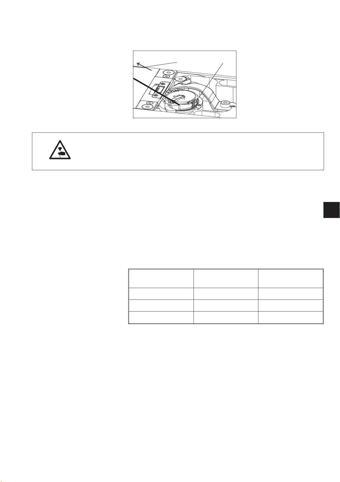
6.3 Inserting the bobbin and threading the hook thread
2
3
10
6
1
4
5
Caution! Risk of injury!
Turn off the main switch.
The hook-thread bobbin may only be changed with the machine
switched off.
–
Tilt the shutter (1) up.
–
Insert the bobbin (2) with the thread end (3) oriented according to
the picture.
–
Thread the thread through the slit (4) and space (5), hook upon the
shutter (1) and fasten it under the spring (6).
–
Trim the thread ends according to the picture.
10
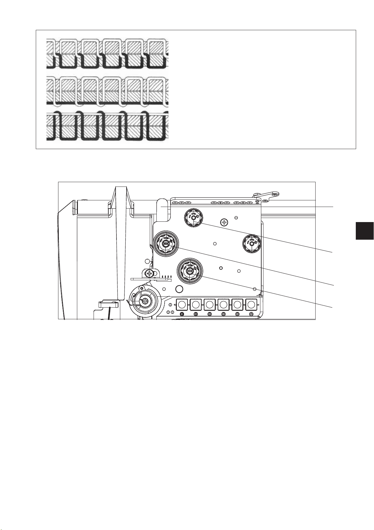
6.4 Adjusting the thread tension
6.4.1 Adjusting the hook thread tension
Caution! Risk of injury!
Turn off the main switch.
The hook thread tension may only be adjusted with the machine
switched off.
–
–
13
Adjust the hook thread tension by the screw (1) with a screwdriver.
The tension is increased by tightening the screw.
Measure the thread tension with a dynamometer. Thread the
thread according to the picture and pull in the arrow direction (3).
This tension is adjusted in the factory in dependence on the
selected sewing equipment according to the below table, and it is
suitable for the usual sewing operations. For sewing thin soft
materials, it is necessary to reduce the tension. If the seam is to be
tightened strongly, it is necessary to increase the tension and
reduce the sewing speed at the same time.
GB
Hook thread tension mean value
Sewing category Needle used
thread Nadelstärke Nm
light 70-80 50
medium 90-110 65
heavy 120-160 90
Tension in
grams
11

6.4.2 Adjusting the needle thread tension
1
2
3
4
Supplementary tensioner adjustment (1)
–
Adjust the supplementary tensioner (1) so that it has the lowest
tension possible, but so high that, when taking out the sewn
material after the preceding trimming (when the tensioners (2)
and (3) are switched off), the thread is not pulled out of the
tensioner (1). (Tensioner (1) is not switched off at the foot lifting).
Tensioner (2) and (3) adjustment
The machine can be equipped with a lever (4) for the tensioner (2)
temporary switching off. In this case, two thread tension values can be
pre-selected and a good stitch tightening can be achieved when
sewing over a variable number of layers of the sewn material with one
seam.
–
Switch the tensioner off (2) with the lever (4) and sew on a smaller
number of layers.
–
Regulate the thread tension with the tensioner (3), till a good
thread loop is achieved (see opposite figure).
–
Switch the tensioner on (2) by the lever (4) shifting out and sew on
a greater number of layers.
–
Regulate the thread tension with a tensioner (2), till a good thread
loop is achieved (see opposite figure).
–
If the machine is not equipped with the lever (4), regulate the
tension by both tensioners (2) and (3) at the same time so that their
nuts are screwed approximately in the same height.
12
Correct thread interlacing in the center
of the material
Needle-thread tension too low
or
hook-thread tension too high
Needle-thread tension too high
or
hook-thread tension too low
6.5 Switching the thread tensioner on/off
1
GB
All machines
–
When pulling the hand lever (1) towards the operator, the
tensioners (3) and (4) are switched off.
–
Tensioner (2) is never switched off.
Manually controlled machines (without the thread trimming)
–
Tensioners (3) and (4) are mechanically switched off when the foot
is lifted with a hand or knee lever.
Machines with the thread trimming
–
Tensioners (3) and (4) are switched off with an electric magnet or
pneumatic cylinder at the foot automatic lifting. If the automatic foot
lifting at the machine stop is pre-selected, the tensioners are
switched off, but temporarily only, so that the switching off electric
magnet does not overheat.
–
Tensioners (3) and (4) are also switched off temporarily during the
trimming cycle.
–
Tensioners (3) and (4) are not switched off at the foot lifting with
the hand or knee lever.
2
3
4
13

6.6 Adjusting the thread regulator
2
1
The thread regulator (2) controls the quantity of needle thread required
for stitch formation.
The thread regulator must be precisely adjusted for an optimum result.
–
Loosen the screw (1), shift the thread regulator (2), and tighten the
screw (1).
–
For most of the sewing operations, the regulator optimal setting is
with its right edge corresponding to the No. 2.
–
For a thin material layer and a very short stitch only, the setting
corresponding to the No. 3 is suitable.
1234
14

6.7 Needle change
1
2
MAX. 3°
3
4
5
Caution! Risk of injury!
Turn off the main switch.
The needle may only be changed with the sewing machine switched
off.
GB
–
Draw the lever (1) in your direction to loosen the screw fixing the
needle.
–
Remove the needle and insert a new one with the needle scarf (2)
to the right according to the section (3) or (4). The needle may not
be oriented according to the section (5).
–
Turn the lever (1) back to tighten the needle fixing screw.
Caution!
A false orientation of the needle turning may cause the hook point
destruction.
When changing to another needle size, the distance between hook
and needle must be readjusted (see service instructions).
15
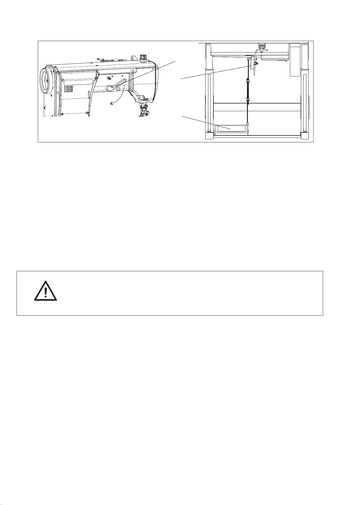
6.8 Lifting and folding the roller presser
Lifting the roller presser with a hand lever
–
Lift the roller presser by the lever turning (1) in the arrow direction
to the stop (the roller presser remains lifted, the lever (1) remains
tilted).
–
Lower the roller presser by putting the lever (1) to the initial
position, or by pressing the knee lever (3) and its subsequent
release.
–
After the roller presser lifting with the hand lever, the machine may
be started up (e. g. at the hook thread winding).
1
3
4
Roller presser lifting with the knee lever
–
The roller presser is lifted by pressing the lever (3); the roller
presser is lowered at the lever release.
Caution!
At the roller presser lifting higher than 6 mm over the throat plate the
machine may not operate, otherwise the needle bar with the needle
holder hits the roller presser, or the needle guides of the double needle
machines.
Roller presser lifting with a pedal - automatically
–
The roller presser lifting in the machines equipped with a
positioning motor (drive) can be controlled by the pedal (4)
treading in the position -1 (see par.6.13.1). The roller presser is
lifted to the upper dead point by means of an integrated electric
magnet or pneumatic cylinder. After the pedal is released, the roller
presser is lowered.
–
It is possible to pre-select the automatic roller presser lifting at
each machine stop without the necessity to tread the pedal in the
position to the position -1. In this case, the roller presser is lowered
at the pedal treading in the position +1. After the finishing of the
seam, the roller presser remains lifted permanently.
16

Roller presser folding
–
Lift the roller presser with the hand lever.
–
Lift the roller presser by pressing in the signed direction.
Caution! Risk of injury!
Roller presser folding to be done at main switch off and standing
motor.
6.9 Sewing-foot pressure
1
+
–
Regulate the roller presser pressure with the setting wheel (1).
–
To incre ase the roller pres se r pressu re = turn the setting wheel (1)
clockwise.
To decre ase the ro lle r pre sser pressur e = turn the setting wheel (1)
anti-clockwise.
–
The roller pressure is to be as small as possible, but strong enough
that the roller presser is not lifted by the needle friction in the
material during the upward movement and that the feeding is
reliable.
–
The maximum roller presser pressure is 100N in the machine
equipped with electric magnets, and in the machine with the
pneumatic cylinders 160N.
GB
17

6.10 Reverse sewing (Backtacking)
Backtacking with a hand lever
–
Press the lever (1) downwards. As long as the reverse feed
lever (1) is pressed down, the machine sews in reverse.
Backtacking with a key
–
Press the key (2) or lever (3). The machine sews in reverse, as
long as the key (2) or lever (3) is pressed down.
Automatic backtacking (bartacking)
In the machines equipped with the positioning motor it is possible to
pre-select the backtacking by a pre-selected backstitches number both
at the beginning and at the seam end. At the seam beginning (after the
preceding thread trimming) after the pedal treading forwards the
machine sews the pre-selected bartack entirely automatically. The
same at the seam end after the pedal treading in the position –2 the
machine sews the pre-selected end bartack and then trims the threads.
1
2
3
18

6.11 Setting the stitch length
1
2
3
–
Turn the button (1) so that the number (2) indicating the required
stitch length in mm is opposite the mark (3).
6.12 Starting up the manually controlled machine with a clutch motor
–
Switch on the motor (1) with a switch (2) – the drive motor operates
permanently.
–
Tread the pedal (3). The motor friction clutch gets switched and the
sewing machine starts running.
–
Regulate the sewing speed by the pressure on the pedal (3).
Dependent on this pressure, the clutch slip changes and
subsequently the machine speed as well.
–
Release the pedal (3). The sewing machine stops.
GB
2
1
3
19

6.13 Controlling the machine equipped with a positioning motor
6.13.1 By a control pedal
-2
-1
0
1
2
13
The pedal position is scanned by a sensor distinguishing 16 levels.
The meaning is given in the table:
Pedal position Pedal motion Meaning
-2 Over heel fully backwards Command for thread trimming
(seam finishing)
-1 Over heel slightly backwards Command for foot lifting
0 Neutral position See notes
1 Slightly forwards Command for foot lowering
2 Further forwards Sewing at minimum speed
(1. speed gear)
3 Further forwards Sewing - 2. speed gear
:: :
13 Fully forwards Sewing at maximum speed
(12. speed gear)
Note: In addition to the neutral position, it is possible to pre-select the
needle position (down/up) and the foot position (down/up) at the
stopping in the seam (by the pedal positioning in the neutral position),
the foot position (down/up) after the seam finishing (by the pedal
treading fully backwards and positioning the pedal in the neutral
position).
20

6.13.2 By a key panel
Key Function
1 Manual bactacking
2 Needle positioning to the upper or lower position
3 Calling out/cancellation of the start or end bartack
4 Half length stitch
7 810911123 4
When the key is pressed during the sewing, the sewn material is fed backwards.
By parameter F-140 (Efka DA82GA); F-242 (DA321) the following function keys can
be defined:
1 = needle up (DA82GA); needle up/down (DA321)
2 = needle up/down (DA82GA); needle up (DA321)
3 = one stitch
4 = one stitch with the second/shorter stitch length (in machines with this equipment)
5 = needle up, if it is out of position 2
(factory setting is 1 = needle up)
If the start and end bartack are switched on, the following bartack is switched
off by pressing the key.
If the start and end bartack are switched off, the following bartack is switched on
by pressing the key.
By pressing the key 1 stitch of half length is sewn.
GB
LED Function
8 and 9 Warning of an empty bobbin in the machines with rest bobbin thread
sensor (left/right bobbin).
10 LED signals the network switching on
Through the arresting of the pin 11 under the key 1 it is possible to transfer the
key 1 function to key 7:
- select the function (e. g. 1 = manual backtacking)
- turn the pin 11 under the key 1 by 90° clockwise (the groove is vertical)
The manual backtacking function can be called out by the keys 1 and 7 now.
CAUTION!
Before key (7) can be programmed with a new function, the former
setting must be deactivated.
21
7. Positioning motor Efka DC1600/DA82GA
7.1 General
For a detailed description of the control unit, please consult the
enclosed current issue of the operating manual of the motor
manufacturer (see also www.efka.net).
8. Positioning motor (drive) Efka VD552/6F82FA
8.1 General
For a detailed description of the control unit, please consult the
enclosed current issue of the operating manual of the motor
manufacturer (see also www.efka.net).
22

9. Positioning drive Efka DC1550/DA321G
9.1 General
For a detailed description of the control unit, please consult the
enclosed current issue of the operating manual of the motor
manufacturer (see also www.efka.net).
GB
23

10. Sewing with machine with positioning motor (drive)
10.1 Machine automatic functions
The machine has the below functions which are automatically
performed during the seam sewing depending on:
–
Pre-selection
–
Pedal position (according to the machine operator´ s selection)
–
Working phase of seam sewing
Automatic function
Needle positioning
Bartacks
Initial bartack
End bartack
Pre-selection
Needle down at machine stopping in seam
•
Needle up at machine stopping in seam
•
Note: after the seam * finishing the machine stops always
with the needle up.
Standard
•
Decorative**
•
Single
•
Double
•
Standard bartack stitch number forwards
•
Decorative bartack stitch number forwards
•
Standard bartack stitch number backwards
•
Decorative bartack stitch number backwards
•
Single
•
Double
•
Standard bartack stitch number backwards
•
•
Decorative bartack stitch number backwards
•
Standard bartack stitch number forwards
•
Decorative bartack stitch number forwards
Thread trimming
Automatic foot lifting
•
ON
•
OFF
•
Foot lowered at stopping in seam
•
Foot lifted at stopping in seam
•
* The seam is finished after the pedal shifting to the position -2 (if the thread trimming is pre-selected, then after
the trimming).
** The decorative bartack is characterized by the fact that the needle sews stitch in stitch in the previous seam at
the bartacking. At the sewing direction change the machine stops for a moment.
24

10.2 Example of machine operation at sewing
Pre-selection:
Needle down at machine stopping in seam
Standard bartacks
Double initial bartack
Double end bartack
Thread trimming on
Foot lowered at stopping in seam
Foot lifted at seam finishing
Operator´ s action Machine work
Machine stopped. Needle in upper position. Foot lifted in
accordance with pre-selection.
Insertion of sewn material.
Pedal treading to position +1. Foot lowering.
Pedal release to position 0. Foot lifting.
Material position correction.
Pedal treading to position +1. Foot lowering.
Pedal treading to position +3. Sewing of standard double bartack (at speed pre-selected by
producer and subsequent sewing at speed corresponding with
third speed level +3.
Pedal release to position 0. Machine stopping with needle down.
Pedal treading to position -1. Foot lifting.
Turning of sewing material
on needle.
Pedal treading to position +5. Foot lowering and subsequent machine running to fifth speed
grade of sewing.
Pedal treading to position -2. Speed reduction. Sewing of standard double bartack.
Thread trimming under throat plate and machine stopping with
needle up. Foot lifting.
Pedal release. (Foot remains lifted).
Putting out of sewn material.
GB
25

11. Maintenance
11.1 Cleaning and checking
Caution! Risk of injury!
Maintenance may be carried out only with the machine switched off
and the motor stopped!
Maintenance work must be carried out no less frequently than at the
intervals given in the tables (see ”operating hours” column).
Maintenance intervals may need to be shorter when processing
heavy-shedding materials.
2
4
6
5
3
1
7
Maintenance work Explanation Operating
to be carried out hours
Machine head
- Remove lint, pieces of thread
and other debris (e.g. w ith
an air blow gun)
- Remove lint, pieces of thread
and other debris (e.g. w ith
an air blow gun)
- Check the hook Check the clearance of the bobbin housing (6)
Places in special need of cleaning:
- area under the throat plate , feed dog (2),
roller foot.
- area around the hook (1)
- bobbin housing (6)
- thread trimmer
- needle area
CAUTION !
Hold the air blow gun in a way that the lint is
not blown into the oil sump.
Dismantle the throat plate, thread pulling
knife (4), dismantle the hook plunger ring (5),
remove the bobbin housing (6) from the hook.
Clean the inner part of the hook, clean the
bobbin housing - especially the glue
remainder on the surface (7).
and the hook (1).
8
20
500
26

4
3
2
1
Maintenance work Explanation Operating
to be carried out hours
- Clean the oil sump. Cleaning the oil sump (1) for example with
a special vacuum cleaner.
- Clean fan grille. Remove lint and pieces of thread from
air-intake openings (2) and (3) (e.g. with an
air blow gun).
- Check condition and
tension of V-belt.
Check the condition of the V-belt (4).
(check the service instructions).
20
GB
20
500
27
2
4
6
8
10
1
2
3
Maintenance work Explanation Operating
to be carried out hours
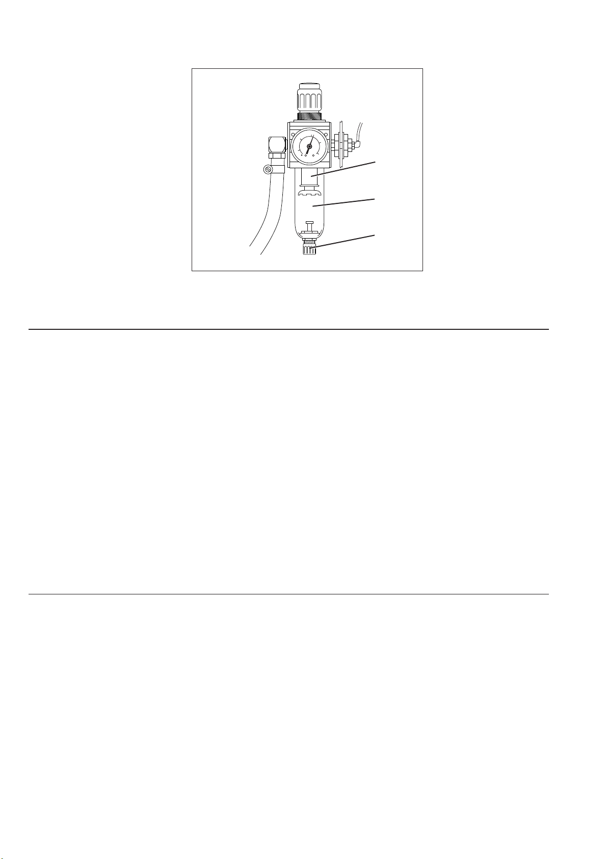
Pneumatic system
- Check water level in
pressure regulator.
- Clean filter cartridge.
- Check the system for leaks.
The water level must not rise to the level of
the filter cartridge (1).
- After unscrewing the drain screw (3), the
water under pressure will flow out of
the water separator (2).
Dirt and condensation are separated out by
the filter cartridge (1).
- Disconnect the machine from the
compressed-air supply.
- Unscrew the drain screw (3).
Theremustbenopressureinthe
machine’s pneumatic system.
- Unscrew water separator (2).
- Unscrew filter cartridge (1).
Wash the filter shell and cartridge
with cleaning fluid (no solvent) and
blast clean.
- Re-assemble the maintenance unit.
40
500
500
28

11.2 Lubrication
2
1
3
Caution: danger of injury
Oil can cause skin eruptions.
Avoid protracted contact with the skin.
In the event of contact, thoroughly wash the affected area.
CAUTION:
The handling and disposal of mineral oils is subject to legal regulation.
Deliver used oil to an authorised collection point.
Protect your environment.
Take care not to spill oil.
GB
To lubricate the special sewing machine use only DA-10 lubricating oil
or an equivalent oil of the following specification:
–
Viscosity at 40° C: 10 mm²/s
–
Flashpoint: 150° C
DA-10 is available from DÜRKOPP ADLER AG retail outlets under the
following part numbers:
250-ml container: 9047 000011
1-litre container: 9047 000012
2-litre container: 9047 000013
5-litre container: 9047 000014
If the oil volume drops to the level (3), supply the oil through the
hole (2) to the “MAX” level.
Check the oil level every day!
All points of the sewing machine head lubricated with oil are supplied
from the central tank (1).
Caution! Risk of failure!
The oil may be supplied only into the central tank or in the hook path.
The other points must not be lubricated separately, so that the oil does
not penetrate to the spots, which must not be lubricated.
29

Notes:
30
 Loading...