

Duerkopp Adler 868 Service Manual

868
Spezialnähmaschine
Serviceanleitung
Service Instructions
D
GB
Postfach 17 03 51, D-33703 Bielefeld • Potsdamer Straße 190, D-33719 Bielefeld
Telefon +49 (0) 521 / 9 25-00 • Telefax +49 (0) 521 / 9 25 24 35 • www.duerkopp-adler.com
Ausgabe / Edition: Änderungsindex Teile-Nr./Part.-No.:
01/2009 Rev. index: 00.0 Printed in Federal Republic of Germany 0791 868641

Alle Rechte vorbehalten.
Eigentum der Dürkopp Adler AG und urheberrechtlich geschützt. Jede, auch auszugsweise Wiederverwendung
dieser Inhalte ist ohne vorheriges schriftliches Einverständnis der Dürkopp Adler AG verboten.
All rights reserved.
Property of Dürkopp Adler AG and copyrighted. Reproduction or publication of the content in any manner, even
in extracts, without prior written permission of Dürkopp Adler AG, is prohibited.
Copyright ©
Dürkopp Adler AG - 2009

General safety instructions
The non-observance of the following safety instructions can cause
bodily injuries or damages to the machine.
1. The machine must only be commissioned in full knowledge of the
2. Before putting into service also read the safety rules and
3. The machine must be used only for the purpose intended. Use of
4. When gauge parts are exchanged (e.g. needle, presser foot, needle
5. Daily servicing work must be carried out only by appropriately
instruction book and operated by persons with appropriate training.
instructions of the motor supplier.
the machine without the safety devices is not permitted. Observe all
the relevant safety regulations.
plate, feed dog and bobbin) when threading, when the workplace is
left, and during service work, the machine must be disconnected
from the mains by switching off the master switch or disconnecting
the mains plug.
trained persons.
6. Repairs, conversion and special maintenance work must only be
carried out by technicians or persons with appropriate training.
7. For service or repair work on pneumatic systems, disconnect the
machine from the compressed air supply system (max. 7-10 bar).
Before disconnecting, reduce the pressure of the maintenance unit.
Exceptions to this are only adjustments and functions checks made
by appropriately trained technicians.
8. Work on the electrical equipment must be carried out only by
electricians or appropriately trained persons.
9. Work on parts and systems under electric current is not permitted,
except as specified in regulations DIN VDE 0105.
10. Conversion or changes to the machine must be authorized by us
and made only in adherence to all safety regulations.
11. For repairs, only replacement parts approved by us must be used.
12. Commissioning of the sewing head is prohibited until such time as
the entire sewing unit is found to comply with EC directives.
13. The line cord should be equipped with a country-specific mains
plug. This work must be carried out by appropriately trained
technicians (see paragraph 8).
It is absolutely necessary to respect the safety
instructions marked by these signs.
Danger of bodily injuries !
Please note also the general safety instructions.


Contents Page:
Service Instructions Class 868
(Edition 01/2009)
1. General notes
1.1 Gauges..................................................... 3
1.2 Descriptionofthelockingpositions.................................... 6
1.3 Graduation on the handwheel ....................................... 7
2. Sewing machine
2.1 Positionofthearmshaftcrankonthearmshaft............................ 8
2.2 Upper and lower toothed belt wheel / toothed belt ........................... 9
2.2.1 Position of the upper toothed belt wheel ................................. 9
2.2.2 Position of the lower toothed belt wheel ................................. 10
2.3 Bottom feed and stitch regulator gear .................................. 11
2.3.1 Basicsettingofstitchadjustment..................................... 11
2.3.2 Adjusting the 2nd stitch length ....................................... 13
2.3.3 Positionoftheadvanceshaft ....................................... 14
2.3.4 Feed gear basic setting ........................................... 15
2.4 Needle bar linkage .............................................. 16
2.4.1 Align the needle bar linkage laterally ................................... 16
2.4.2 Transmissionlever.............................................. 17
2.4.3 Threadlever ................................................. 18
2.5 Postbedfeed................................................. 19
2.5.1 Aligningthepostbedfeed......................................... 19
2.5.2 Feeding motion of the feed dog ...................................... 20
2.5.3 Liftingmotionofthefeeddog ....................................... 21
2.5.4 Feeddogheight ............................................... 22
2.5.5 Balanceweight................................................ 23
2.5.6 Needle penetration in feeding direction ................................. 24
2.6 Hook, looping stroke and needle bar height ............................... 25
2.6.1 Hookheight.................................................. 25
2.6.2 Looping stroke ................................................ 27
2.6.3 Needle bar height .............................................. 28
2.6.4 Distance between hook and needle.................................... 29
2.6.5 Needle guard ................................................. 30
2.7 Bobbin case opening ............................................ 31
2.7.1 General .................................................... 31
2.7.2 Setting of the bobbin case opening .................................... 31
2.7.3 Timing of opening .............................................. 33
2.8 Feeding foot and presser foot ....................................... 34
2.8.1 Basic stroke gearing setting ........................................ 34
2.8.2 Feeding foot and presser foot stroke ................................... 36
2.8.3 Stroke motion of the feeding foot ..................................... 37
2.8.4 Sewingfootpressure............................................ 38
GB

Contents Page:
2.9 Stitch length limitation ............................................ 39
2.10 Stitch equality of the forward and backward stitch ........................... 40
2.11 Sewingfootlifting .............................................. 41
2.11.1 Mechanical sewing foot lifting ....................................... 41
2.11.2 Height of the sewing feet arrested with hand lever ........................... 42
2.11.3 Heightoftheliftedsewingfeet....................................... 43
2.12 Thread-guiding parts ............................................ 44
2.12.1 Thread regulator ............................................... 44
2.12.2Threadtake-upspring............................................ 45
2.13 Bobbin winder................................................. 46
2.14 Threadcutter................................................. 48
2.14.1 General .................................................... 48
2.14.2 Thread-pulling knife height ......................................... 49
2.14.3 Thread-pulling knife ............................................. 50
2.14.4 Swing range of the thread-pulling knife ................................. 52
2.14.5 Counter-knife and lower thread clamp .................................. 53
2.14.6Trimmingposition .............................................. 55
2.15 Potentiometerinthearm.......................................... 56
2.15.1 Basic setting without control panel .................................... 57
2.15.2 Basic setting with the control panel V810 or V820 ........................... 57
2.15.3Checkthepotentiometeradjustment................................... 58
2.16 Connections PCB .............................................. 59
3. Oil lubrication
3.1 Hooklubrication ............................................... 61
3.2 Maintenance ................................................. 62
1. General notes
The present service instructions describes the adjustment of the
special sewing machine 868.
ATTENTION !
The operations described in the service instructions must only be
executed by qualified staff or correspondingly instructed persons
respectively!
Caution: Risk of injury !
In case of repair, alteration or maintenance work turn off the main
switch and disconnect the machine from the pneumatic supply s ystem.
Carry out adjusting operations and functional tests of the running
machine only under observation of all safety measures and with
utmost caution.
The present service instructions describes the adjustment of the
sewing machine in an appropriate sequence. Please observe in
this connection that various setting positions are interdependent.
Therefore it is absolutely necessary to do the adjustment
following the described order.
For all setting operations of parts involved in the stitch formation a new
needle without damage has to be inserted.
Machine covers having to be screwed off and on again for checking
and adjusting operations are not mentioned in the text.
GB
1.1 Gauges
Hint:
Some of the shafts of the special sewing machine 867 are provided
with flat spots. This facilitates the adjustment considerably.
In case of all adjustments on flat spots, it is always the first screw in
rotation direction that is put on such a flat spot.
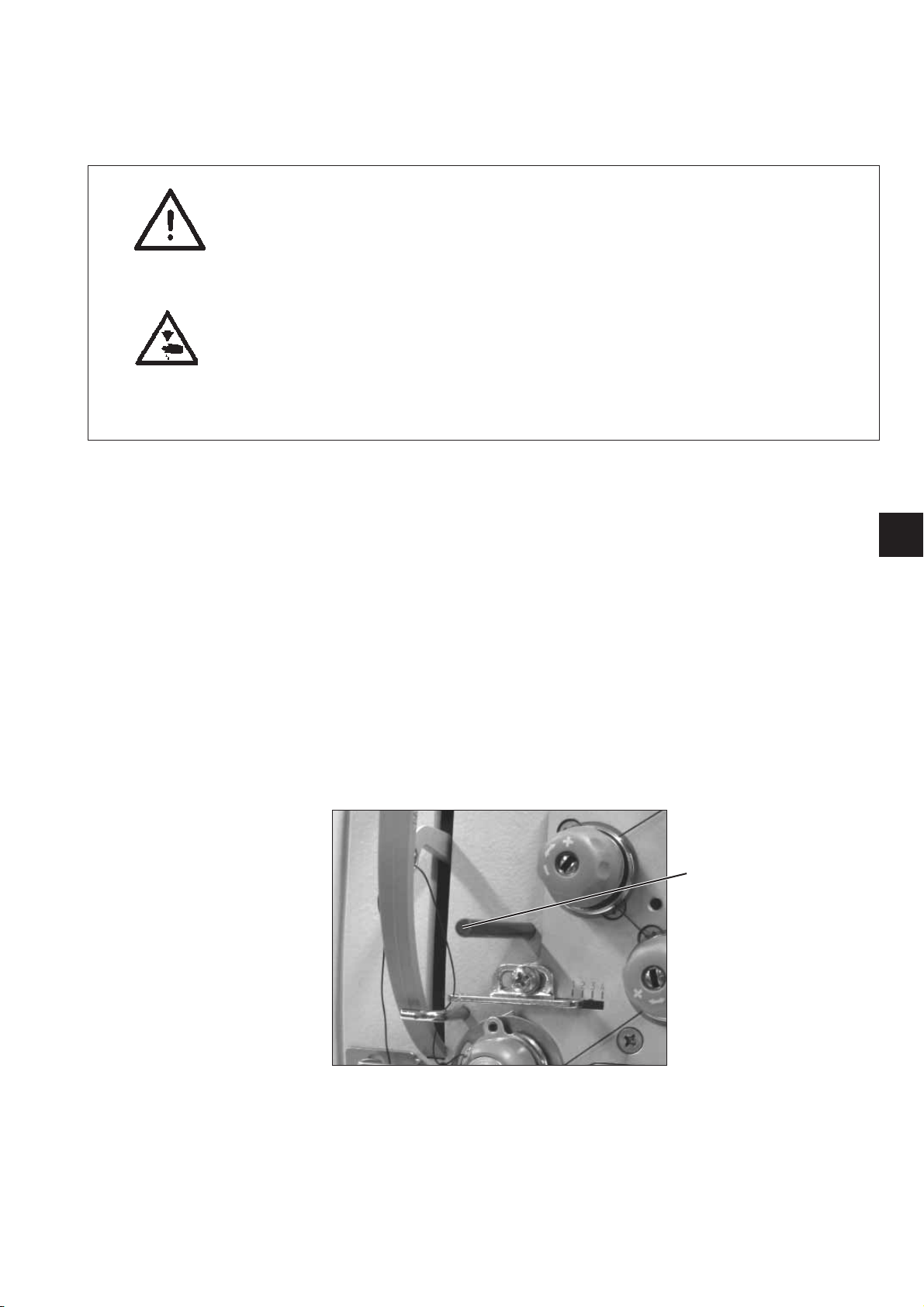
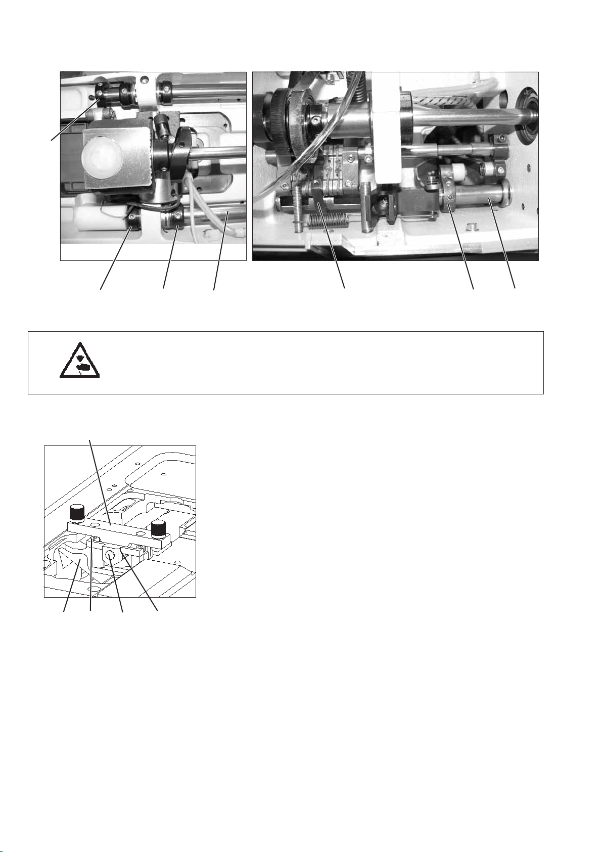
1
The locking pin 1 required for adjusting the machine belongs to the
serial equipment of the machine. It is in the accessories and can be put
at the bottom side of the oil pan.
3
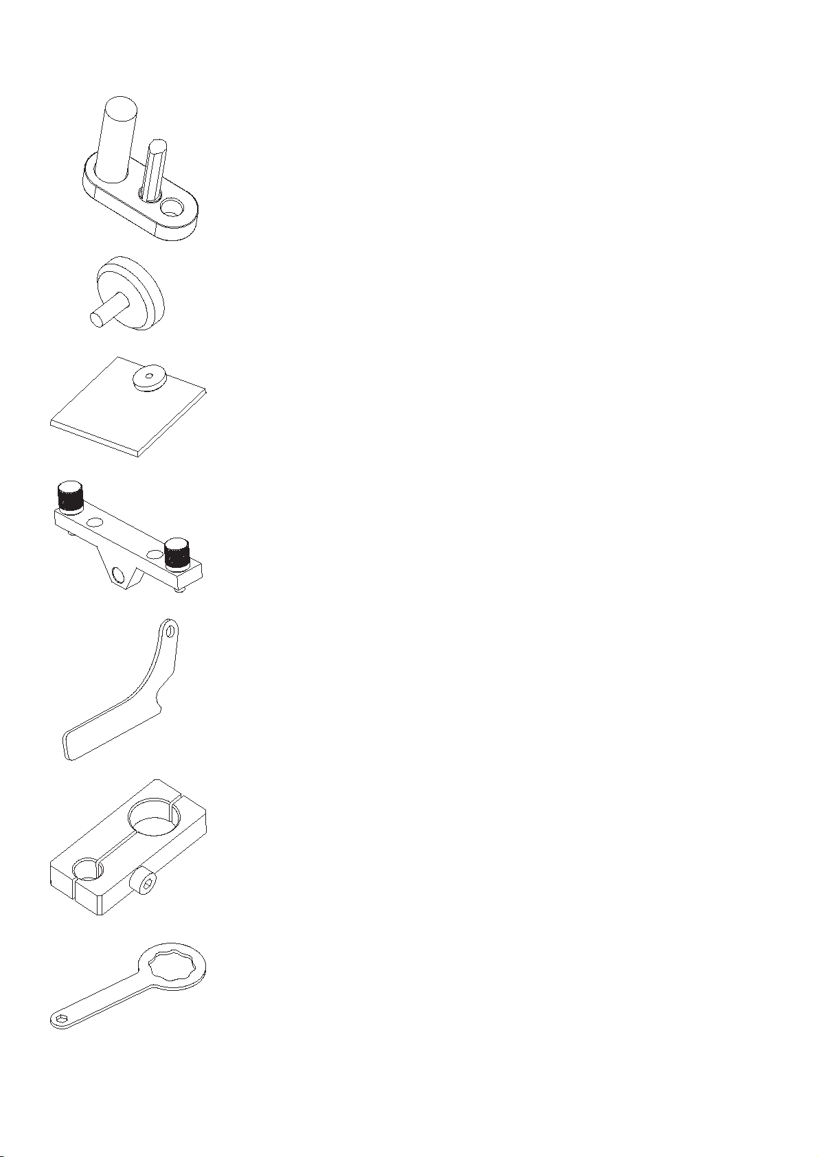
Further gauges:
Setting gauge 0868 290113
chapter 2.4 Needle bar linkage
Setting gauge 0868 290153
chapter 2.5 Post bed feed
Setting gauge 0868 290163
chapter 2.5 Post bed feed
Setting gauge 0868 290184
chapter 2.3.3 Position of the advance shaft
Setting gauge 0868 290020
chapter 2.4.2 Transmission lever
Setting gauge 0868 290194
chapter 2.4 Needle bar linkage
chapter 2.5 Post bed feed
Auxiliary gauge 0667 295050
chapter 2.3.1 Basic setting of stitch adjustment
4

Notes:
GB
5
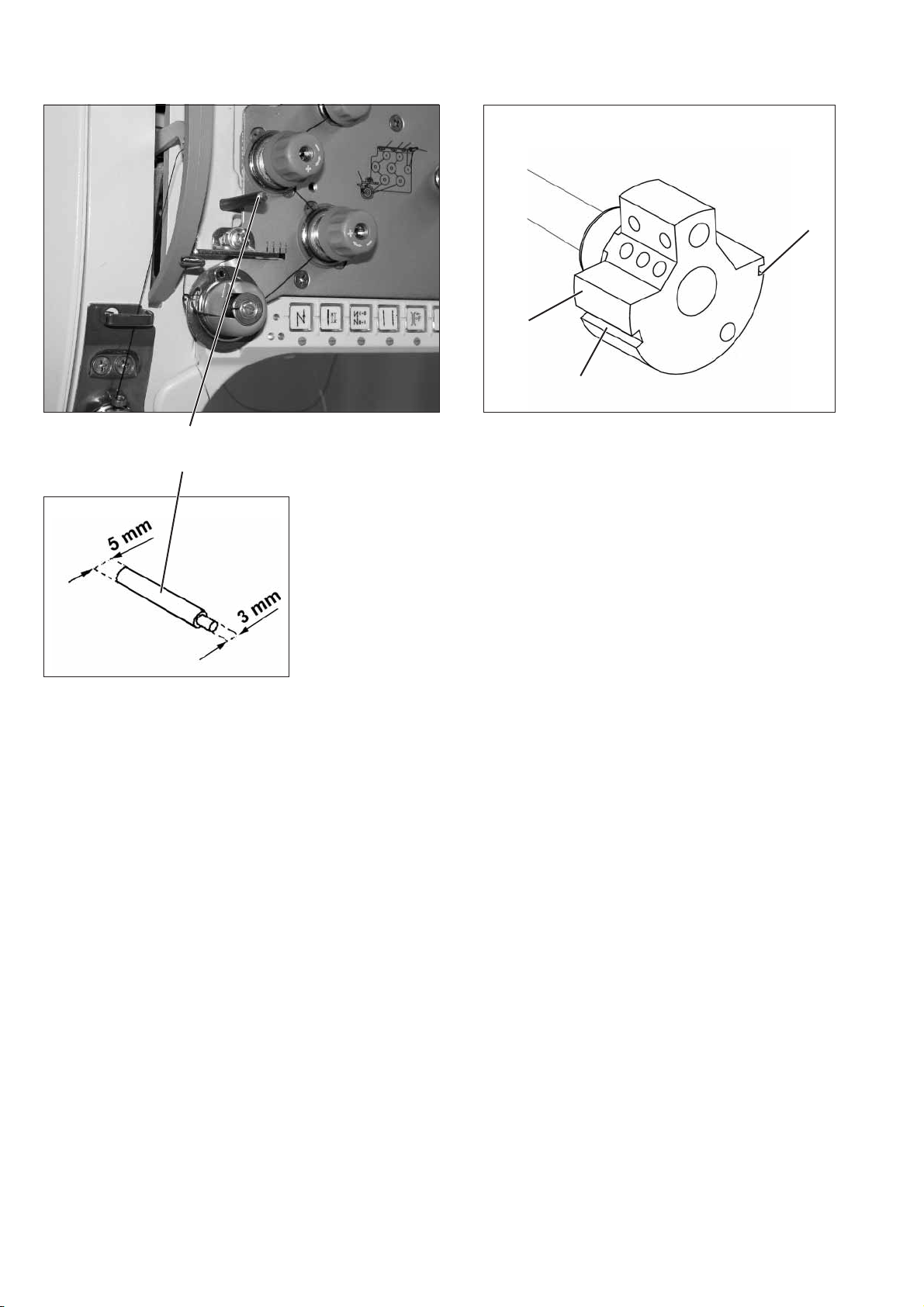
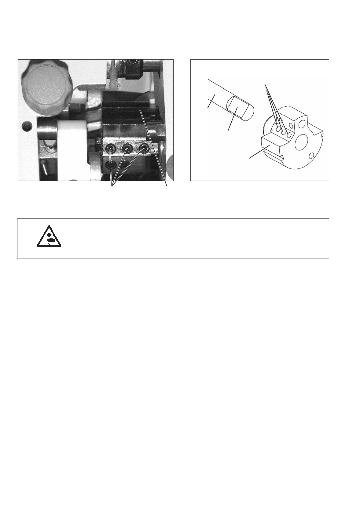
1.2 Description of the locking positions
1
With the locking pin 1 and the arresting grooves 2 and 3 in the arm
shaft crank 4 the sewing machine can be arrested in two adjusting
positions.
3
4
2
Position I = Locking pin Ø5mmfor large groove
= Looping stroke, needle bar height
Position II = Locking pin Ø3mmfor small groove
= Needle bar at its upper dead centre, 0° on the
handwheel.
6

1.3 Graduation on the handwheel
The handwheel 2 has degree marks printed on it.
Certain settings are effectuated by using these handwheel positions.
–
Turn the handwheel until the degree mark mentioned in this manual
points to the index 3.
–
Carry out the described adjustment.
1
2
3
GB
Setting the handwheel
–
Arrest the machine in position II by using the locking pin Ø3mm.
–
Loosen the fastening screw for the handwheel through opening 1.
–
Turn the handwheel so that the degree mark “0" points to the
index 3.
–
Tighten the fastening screw again.
–
Set the handwheel to 50° and tighten the second fastening screw.
7
2. Sewing machine
2.1 Position of the arm shaft crank on the arm shaft
21
2
4
3
1
Caution: Risk of injury !
Turnthemainswitchoff!
Check and set the position of the arm shaft crank only when the
machine is switched off.
Standard checking
The arm shaft crank 1 is fastened with the three screws 2 on the arm
shaft 4. The screws have to sit on the flat spot 3.
Correction
–
Loosen screws 2 at the arm shaft crank.
–
Twist arm shaft crank 1 on the shaft in such a way that
the screws 2 sit on the flat spot 3.
–
Push arm shaft crank 1 axially to the right as far as it will go.
–
Tighten screws 2.
8
2.2 Upper and lower toothed belt wheel / toothed belt
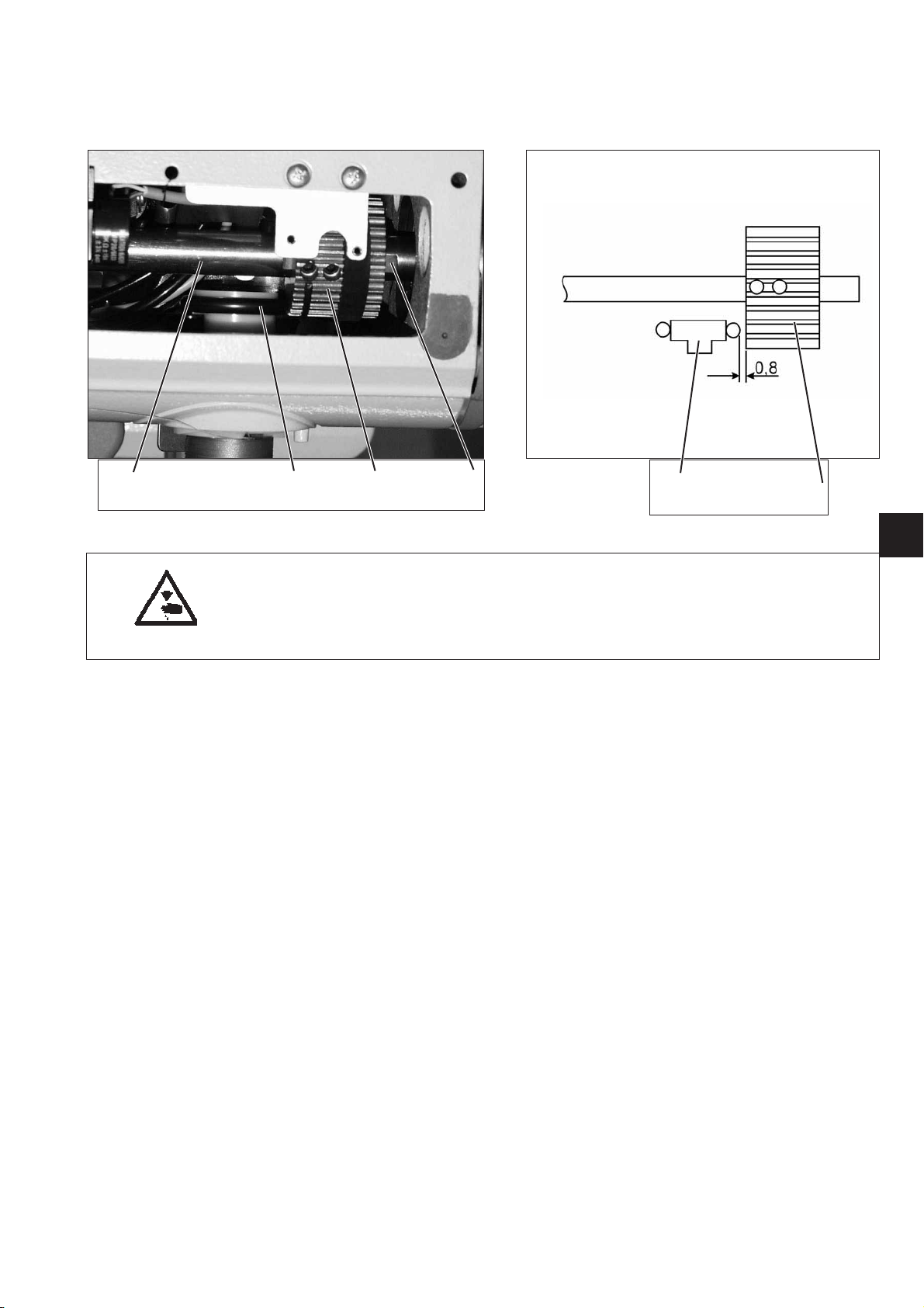
2.2.1 Position of the upper toothed belt wheel
4321
Caution: Risk of injury !
Turnthemainswitchoff!
Check and set the position of the upper toothed belt wheel only with
the sewing machine switched off.
Standard checking
The toothed belt wheel 2 is fastened with two screws on the arm
shaft 4. The screws have to sit on the flat spot 1.
The distance between the toothed belt wheel 2 and the bobbin winder
wheel 3 should amount to 0.8 mm when the bobbin winder is switched
off.
–
Check the distance between the toothed belt w heel 2 and the
bobbin winder wheel 3 by means of a thickness gauge.
Correction
–
Loosen the threaded pin in the toothed belt wheel.
–
Turn the toothed belt wheel, until the screws sit on the flat spot 1
of the arm shaft 4.
–
Set a lateral distance of 0.8 mm between the toothed belt wheel 2
and the bobbin winder wheel 3 by using the thickness gauge.
–
Tighten the threaded pin in the toothed belt wheel.
32
GB
9
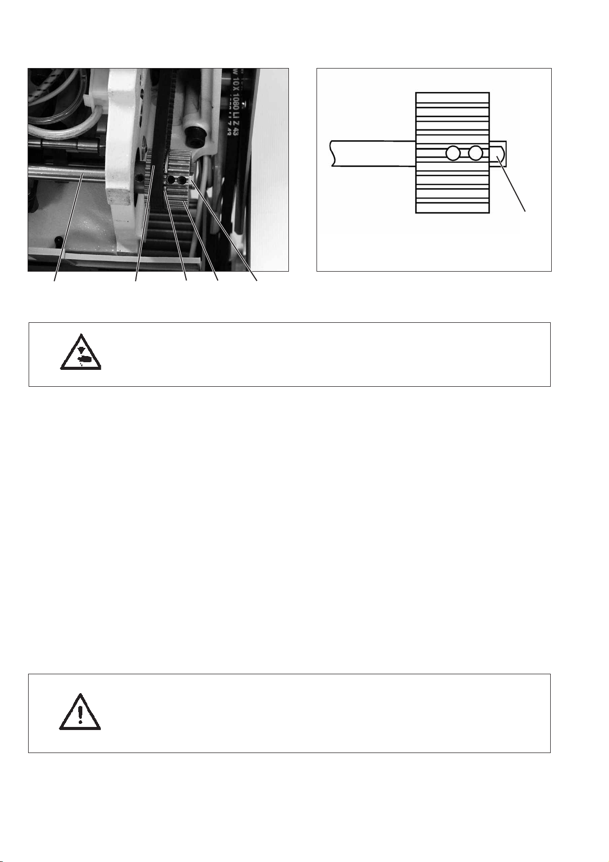
2.2.2 Position of the lower toothed belt wheel
54321
Caution: Risk of injury !
Turnthemainswitchoff!
Check and set the position of the lower toothed belt wheel
only with the sewing machine switched off.
1
Standard checking
The screws in the toothed belt wheel 2 have to sit on the flat spot 1 of
the lower shaft 5.
The toothed belt wheel must be positioned in a way that the toothed
belt 4 bears against the belt tensioner ring 3 but without being
dislocated.
–
Check the position of the toothed belt wheel.
Correction
–
Pull out the toothed belt from the lower toothed belt wheel 2.
–
Loosen the threaded pin in the toothed belt wheel 2.
–
Turn the toothed belt wheel 2, until the screws sit on the flat spot of
the lower shaft 5.
–
Tighten the threaded pin in the toothed belt wheel 2.
–
Put the toothed belt on the toothed belt wheel 2 again.
–
Check the course of the toothed belt.
ATTENTION Danger of breakage !
After replacing the toothed belt, check the following:
Hook adjustment (see chapter 2.6), feeding motion of the
feed dog (see chapter 2.5.2) and lifting motion of the feed dog
(see chapter 2.5.3).
10
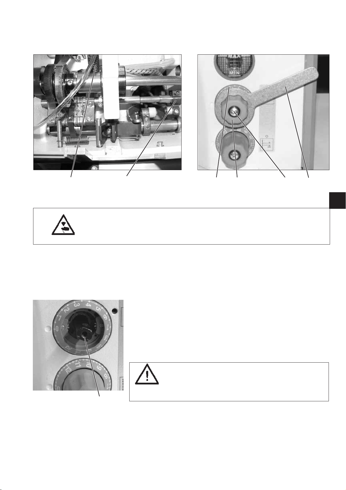
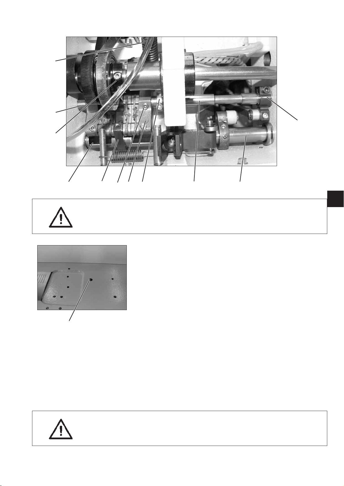
2.3 Bottom feed and stitch regulator gear
2.3.1 Basic setting of stitch adjustment
21
Caution: Risk of injury !
Turnthemainswitchoff!
Set the basic setting of stitch adjustment only with the sewing
machine switched off.
Standard checking
When the setting wheel 5 is set to the position “0", the stitch regulator
gear should not have any clearance.
–
Set stitch length “0” at the setting wheel 5.
–
Check the clearance of the stitch regulator gear at the stitch
regulator lever 1.
Correction
–
Unhook the spring 2.
–
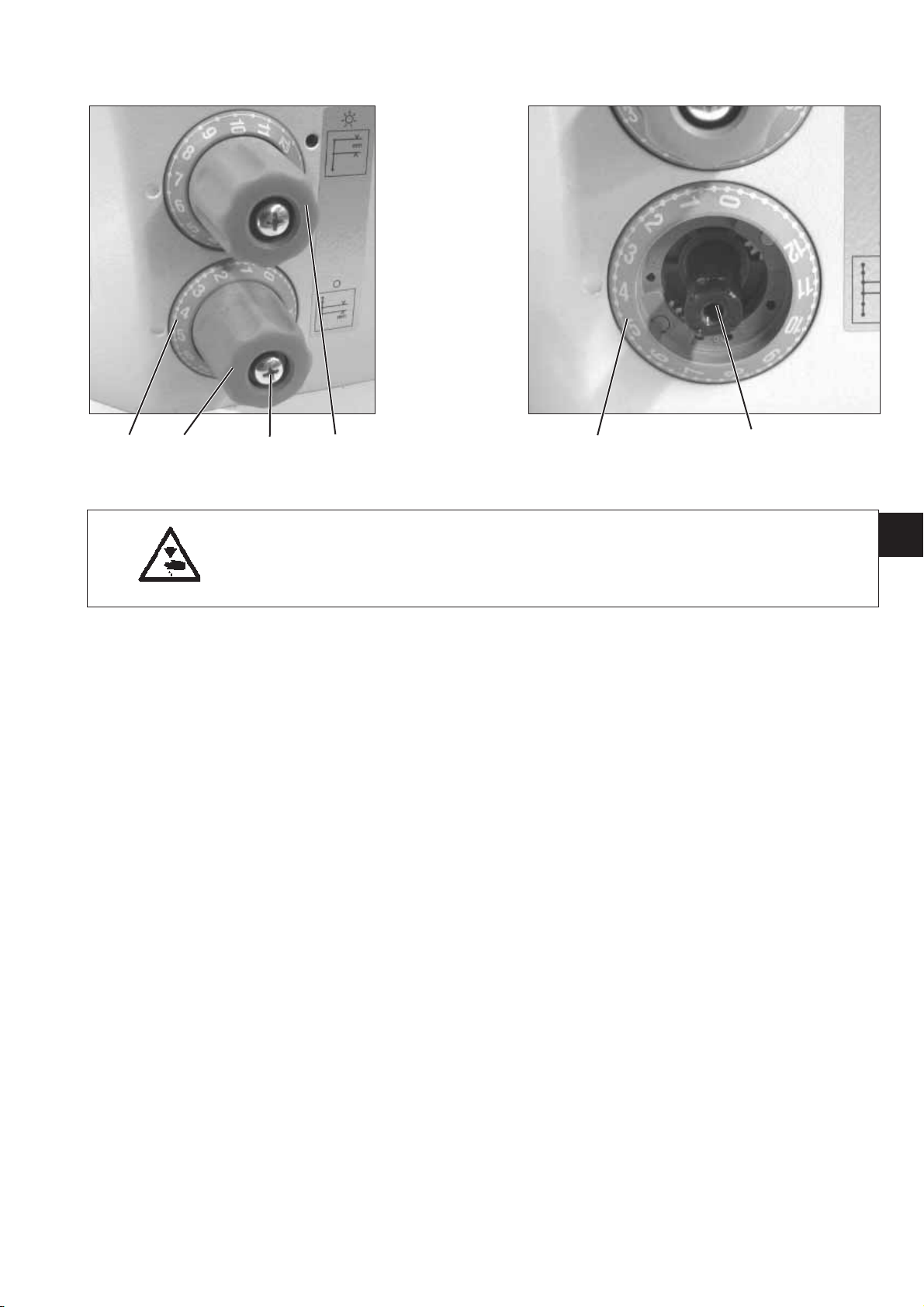
Retain the setting wheel 5 using the wrench 3 (0667 295050).
–
Unscrew screw 4 and pull off the setting wheel 5.
–
Turn the shaft 7 to the right using a 10 mm w rench until the stitch
regulator lever 1 has no more clearance.
65 4 3
GB
ATTENTION: Danger of breakage !
Do not turn the shaft too far to the right .
The stitch regulator parts may jam and the
maximum stitch length of 8 mm and 6 mm
can respectively no longer be achieved.
7
–
Set the scale 6 to “0”.
–
Put the setting wheel 5 on again and tighten it with screw 4.
–
Put the spring 2 back in place again.
–
Check the clearance of the stitch regulator lever 1.
11

1
32
3
4
2
12
Adjusting the eccentric
The eccentric 3 has to be adjusted so that the open end 4 of the
eccentric slot superposes with screw 2.
–
Loosen screw 2.
–
Turn the eccentric 3 through the bore hole 1 so that the open end 4
of the eccentric slot points to screw 2.
–
Tighten screw 2.
2.3.2 Adjusting the 2nd stitch length
43 2 1
Caution: Risk of injury !
Turnthemainswitchoff!
Set the basic stitch adjustment only with the sewing
machine switched off.
–
Set the upper setting wheel 1 to “0”.
–
Unscrew screw 2 and pull off the setting wheel 3.
–
Cautiously turn the shaft 5 byusinga10mmwrenchinclockwise
direction as fas as it will go.
–
Set the scale 4 to position “0”.
–
Put the setting wheel 3 back on again an tighten it with screw 2.
45
GB
13
2.3.3 Position of the advance shaft
6
231 4 51
7
912 8 10
Caution: Risk of injury !
Turnthemainswitchoff!
Set and check the feed dog and the stitch adjustment gear only
with the sewing machine switched off.
–
Unscrew the advance shaft.
–
Loosen the screws on the adjustment rings 2 and 3.
–
Loosen the clamping screw on the lever 4.
–
Loosen the screws on the lever 5 (2x).
–
Loosen the screws on the lever 6 (2x).
–
Slightly screw the holder 10 onto the feed dog beam 9.
–
Screw the gauge 7 (0868 290184) onto the bed plate.
–
Connect holder 10 with the gauge 7 by using the bolt 8.
–
Align the feed dog beam 9 according to the holder 10.
–
Tighten screws 12 (2x) of the holder 10 again.
–
Arrest the s haft 1 with the adjustment rings 2 and 3 and tighten the
screws.
–
Set the stitch length to “0" and fasten the clamping screw on the
lever 4.
–
Position the needle bar in the centre by using the gauge
0868 290194 and tighten the screws on the lever H ebel 5 (2x)
(note chapter 2.4.2).
–
Tighten the screws on lever 6 (2x) (note chapter 2.5.4 - Feed dog
height).
–
Unscrew gauge 7.
14
2.3.4 Feed gear basic setting
1
8
5
743109 11 7
2
GB
Caution: Risk of injury !
Turnthemainswitchoff!
Set and check the feed dog and the stitch adjustment gear only
with the sewing machine switched off.
–
Unhook spring 1.
–
Loosen the clamping screw on the block 2.
–
Loosen the clamping screw on the block 4.
–
Loosen screw 6.
–
Align the positioning frame 10 laterally so that it sits centrical
between the cutouts on the shaft 7.
–
Arrest the positioning frame 10 axially with the bearing bolt 8
(fastened with screw 6) and adjustment ring 9.
–
Set the upper stitch setting wheel (chapter 2.3.2) to “0“.
–
Twist the positioning frame 10 so that the tongues come parallel to
6
each other.
–
Tighten the clamping screw on the block 2.
–
Tighten the clamping screw on the block 4.
–
Refit spring 1 on the positioning frame 10 and on the fastening
bracket.
Note: The shaft 11 is fixed on the level of the positioning
frame 10 in position 3 with two screws in tandem
arrangement on a flat spot.
ATTENTION: Danger of breakage !
The shaft 11 must not reach so far into the positioning frame 10
that the tongues are hindered in their movements.
15
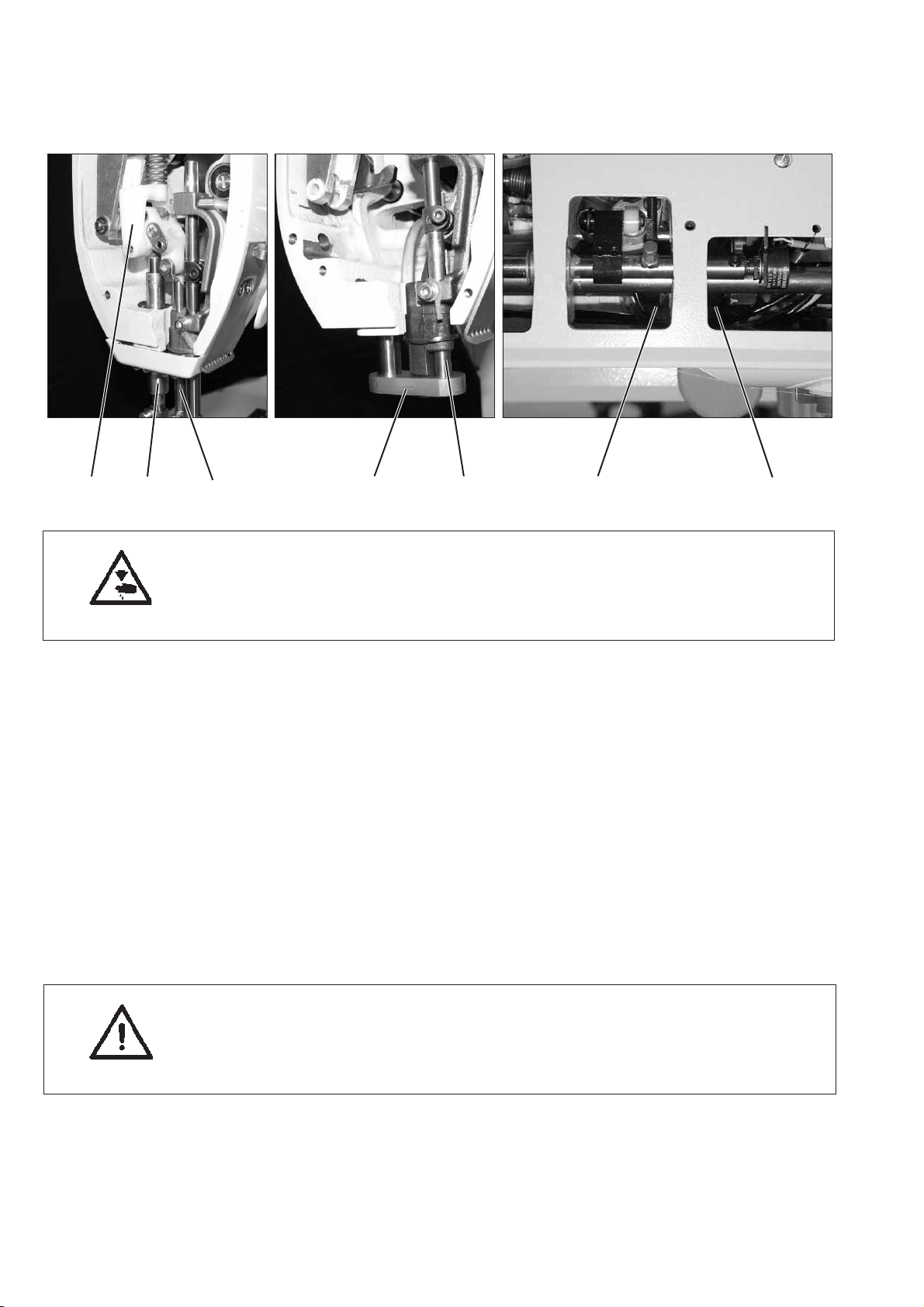
2.4 Needle bar linkage
2.4.1 Align the needle bar linkage laterally
435617 2
Caution: Risk of injury !
Turnthemainswitchoff!
Check and set the needle bar linkage only with the sewing
machine switched off.
–
Loosen the screws on the adjustment rings 3 and 4.
–
Remove the spring-loaded guide 1 and the bushing 7.
–
Remove the feeding foot bar 2.
–
Insert the gauge 5 (0868 290113) as shown in the photograph.
–
Insert the needle bar 6 without needle block and thread guide into
the bore hole of gauge 5.
–
Fix the adjustment rings 3 and 4 and tighten the screws.
–
Remove the gauge 5.
–
Mount the spring-loaded guide 1 the feeding foot bar 2 and the
bushing 7 again.
16
ATTENTION: Danger of breakage !
Check the distance between the hook tip and the needle after
adjusting the lateral position of the needle bar linkage.
If necessary, readjust the distance (see chapter 2.6.4).
 Loading...