


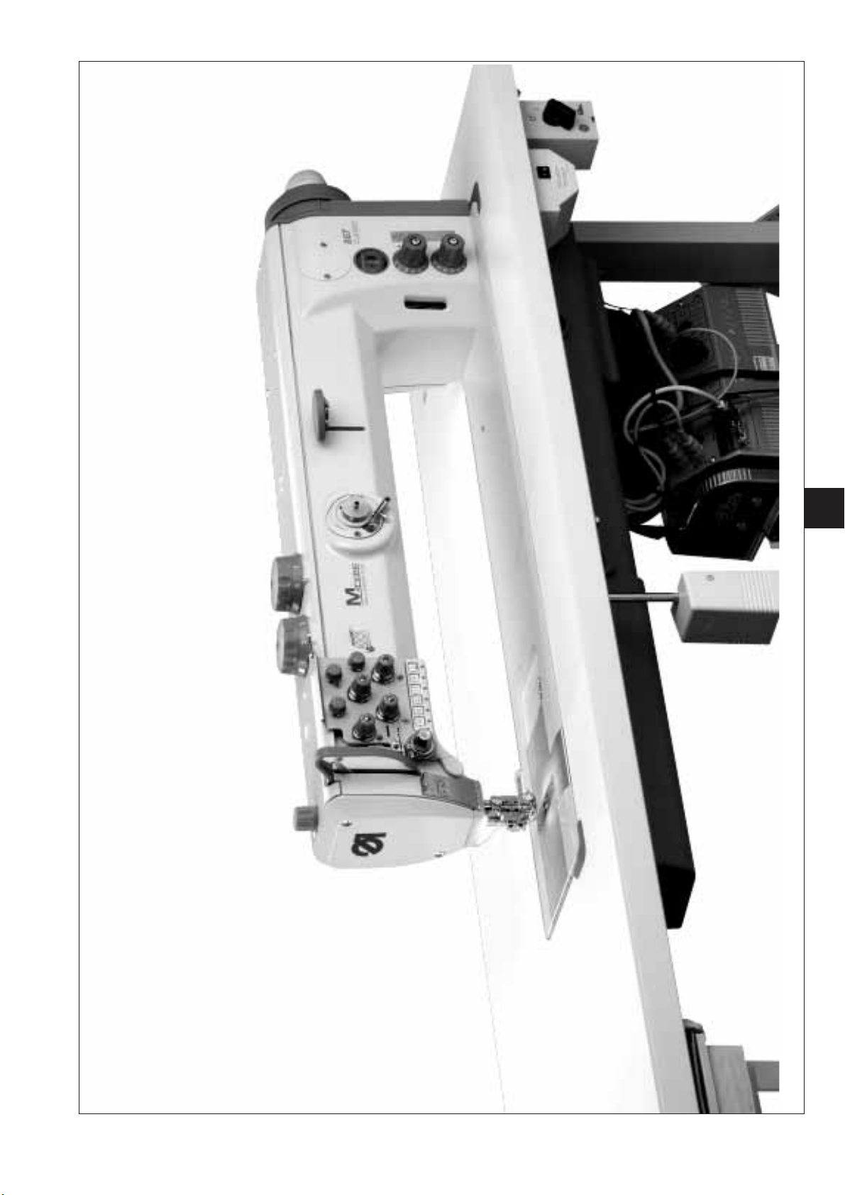
867
Spezialnähmaschine
Betriebsanleitung
Instruction manual
Instructions d’emploi
D
GB
F
Postfach 17 03 51, D-33703 Bielefeld • Potsdamer Straße 190, D-33719 Bielefeld
Telefon +49 (0) 521 / 9 25-00 • Telefax +49 (0) 521 / 9 25 24 35 • www.duerkopp-adler.com
Ausgabe / Edition: Änderungsindex Teile-Nr./Part.-No.:
01/2008 Rev. index: 02.0 Printed in Federal Republic of Germany 0791 867740

Alle Rechte vorbehalten.
Eigentum der Dürkopp Adler AG und urheberrechtlich geschützt. Jede, auch auszugsweise Wiederverwendung
dieser Inhalte ist ohne vorheriges schriftliches Einverständnis der Dürkopp Adler AG verboten.
All rights reserved.
Property of Dürkopp Adler AG and copyrighted. Reproduction or publication of the content in any manner, even
in extracts, without prior written permission of Dürkopp Adler AG, is prohibited.
Tous droits réservés.
Propriété de la société Dürkopp Adler AG et protégé par la loi sur le droit d’auteur. Une copie ou reproduction
par quelque procédé que ce soit du contenu sans accord écrite de l’auteur est interdite.
Copyright ©
Dürkopp Adler AG - 2008

Foreword
This instruction manual is intended to help the user to become familiar
with the machine and take advantage of its application possibilities in
accordance with the recommendations.
The instruction manual contains important information on how to
operate the machine securely, properly and economically. Observation
of the instructions eliminates danger, reduces costs for repair and
down-times, and increases the reliability and life of the machine.
The instruction manual is intended to complement existing national
accident prevention and environment protection regulations.
The instruction manual must always be available at the machine/sewing
unit.
The instruction manual must be read and applied by any person that is
authorized to work on the machine/sewing unit. This means:
– Operation, including equipping, troubleshooting during the work
cycle, removing of fabric waste,
– Service (maintenance, inspection, repair) and/or
– Transport.
The user also has to assure that only authorized personnel work on the
machine.
The user is obliged to check the machine at least once per shift for
apparent damages and to immediatly report any changes (including the
performance in service), which impair the safety.
The user company must ensure that the machine is only operated in
perfect working order.
Never remove or disable any safety devices.
If safety devices need to be removed for equipping, repairing or
maintaining, the safety devices must be remounted directly after
completion of the maintenance and repair work.
Unauthorized modification of the machine rules out liability of the
manufacturer for damage resulting from this.
Observe all safety and danger recommendations on the machine/unit!
The yellow-and-black striped surfaces designate permanend danger
areas, eg danger of squashing, cutting, shearing or collision.
Besides the recommendations in this instruction manual also observe
the general safety and accident prevention regulations!

General safety instructions
The non-observance of the following safety instructions can cause
bodily injuries or damages to the machine.
1. The machine must only be commissioned in full knowledge of the
2. Before putting into service also read the safety rules and
3. The machine must be used only for the purpose intended. Use of
4. When gauge parts are exchanged (e.g. needle, presser foot, needle
5. Daily servicing work must be carried out only by appropriately
instruction book and operated by persons with appropriate training.
instructions of the motor supplier.
the machine without the safety devices is not permitted. Observe all
the relevant safety regulations.
plate, feed dog and bobbin) when threading, when the workplace is
left, and during service work, the machine must be disconnected
from the mains by switching off the master switch or disconnecting
the mains plug.
trained persons.
6. Repairs, conversion and special maintenance work must only be
carried out by technicians or persons with appropriate training.
7. For service or repair work on pneumatic systems, disconnect the
machine from the compressed air supply system (max. 7-10 bar).
Before disconnecting, reduce the pressure of the maintenance unit.
Exceptions to this are only adjustments and functions checks made
by appropriately trained technicians.
8. Work on the electrical equipment must be carried out only by
electricians or appropriately trained persons.
9. Work on parts and systems under electric current is not permitted,
except as specified in regulations DIN VDE 0105.
10. Conversion or changes to the machine must be authorized by us
and made only in adherence to all safety regulations.
11. For repairs, only replacement parts approved by us must be used.
12. Commissioning of the sewing head is prohibited until such time as
the entire sewing unit is found to comply with EC directives.
13. The line cord should be equipped with a country-specific mains
plug. This work must be carried out by appropriately trained
technicians (see paragraph 8).
It is absolutely necessary to respect the safety
instructions marked by these signs.
Danger of bodily injuries !
Please note also the general safety instructions.

Contents Page:
Part 2: Installation Instructions Class 867
1. Scope of Delivery ............................................ 5
2. General and transport packing .................................... 5
3. Assembling the stand
3.1 Assembling the stand components (Standard) ............................ 7
3.2 Assemblingthetableplate........................................ 7
3.2.1 Machines without edge cutter ...................................... 7
3.3 Assembling the stand components (Long arm)............................ 9
3.4 Assemblingthetableplate........................................ 9
3.5 Settingtheworkingheight........................................ 10
4. Sewing drives
4.1 Drive category, type and use ...................................... 11
4.2 Drive-pack components ......................................... 12
4.3 Fittingthesewingdrive.......................................... 12
4.4 Fitting the pedal .............................................. 12
4.5 Fittingthesewing-drivecontrolformachineswithdirectdrive .................. 13
4.6 Fittingthesetvalueinitiator....................................... 13
4.7 Fitting the pedal .............................................. 14
GB
5. Assembling the machine head
5.1 Fitting the machine head ......................................... 15
5.2 Fittingtheoilsuctiontube........................................ 15
5.3 FittingandtensioningtheV-belt .................................... 17
5.4 Attachingthekneelever......................................... 18
5.5 Fitting the operating panel ........................................ 19
5.6 Fitting the sewing lamp (optional equipment) ............................. 19
6. Electrical connection
6.1 General ................................................... 21
6.2 Checkingthemainsvoltage....................................... 21
6.3 Connecting the sewing drive....................................... 21
6.3.1 Connecting the clutch motor ....................................... 21
6.3.2 Connecting the coupling-positioning actuator ............................ 21
6.3.3 Connecting the direct-current positioning actuator ......................... 21
6.4 Earthing................................................... 22
6.5 Connecting the sewing drive to the mains............................... 23
6.6 Drive-control connection sockets .................................... 23
6.7 Fittingtheproximityswitch ....................................... 24
6.8 Connecting the machine head ..................................... 24
6.9 Directionofrotationofsewingdrive.................................. 25

Contents Page:
6.9.1 Checking the direction of rotation with the coupling-positioning
actuator (mounted under the table) .................................. 25
6.9.2 Changing the direction of rotation with the coupling-positioning
actuator (mounted under the table) .................................. 25
6.9.3 Checkingthedirectionofrotationofthedirect-currentpositioningactuator .......... 26
6.9.4 Changing the direction of rotation of the direct-current positioning actuator .......... 26
6.9.5 Adjusting the positions with the VD552/6F82FA coupling-positioning actuator ......... 26
6.10 Settingmachine-specificparameters ................................. 27
6.10.1 General ................................................... 27
6.10.2 Autoselect.................................................. 27
6.11 Connecting the sewing light transformer (optional equipment) .................. 28
6.11.1 Attaching and connecting the sewing light transformer (optional equipment).......... 28
6.11.2 Connection to the DA321G ....................................... 29
6.12 Connecting the direct drive ....................................... 30
6.12.1 Connecting the Hall sensor (optional equipment) .......................... 30
6.12.2 Connecting the DA321G controls .................................... 32
7. Pneumatic connection
7.1 Pneumatic sewing foot lifting ...................................... 35
8. Lubrication ................................................ 36
9. Sewing test ................................................ 37
GB
3
10
9
1
2
12
3
4
8
11
7
5
6
4

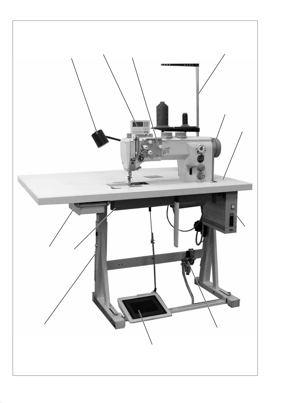
1. Scope of Delivery
What items are supplied depends on your order.
Prior to setting up, please check that all the required parts are present.
This description refers to a special sewing machine, of which all individual
components can completely be delivered by Dürkopp Adler AG.
–
1 Machine head incl. oil sump
Dürkopp Adler accessory set with:
–
2 Reel stand
Protection cover (not represented)
–
11 Oil tray
Set of electronic parts, depending on the order, for:
Machines with direct-current actuator
–
4 Sewing-drive control
–
10 Operating panel
–
12 Cover
Machines with positioning actuators
–
Main switch
–
Sewing-drive
–
Synchronizer
–
Belt guard
Optional equipment
–
7 Stand (option)
–
6 Pedal and pedal linkage (option)
–
3 Table top (option)
–
8 Drawer (option)
–
Knee lever
–
Pneumatic sewing foot lifting
2. General and transport packing
Caution:
The special sewing machine must be set up by trained specialist
personnel.
GB
If the special sewing machine you have bought is already set up, the
following transport packing must be removed:
–
Safety straps and battens on the machine head, table and stand.
–
Safety block and straps on the sewing drive
5
12
Observe the punch-marks of the table plate!
1
13
4,5x15 (x 4)
2
3
11
3,5x17 (x 6)
10
9
14
4
5
6
3,9x15 (x 5)
3,5x17 (x 2)
7
B8x35 (x 4)
8
DIRECT DRIVE
6
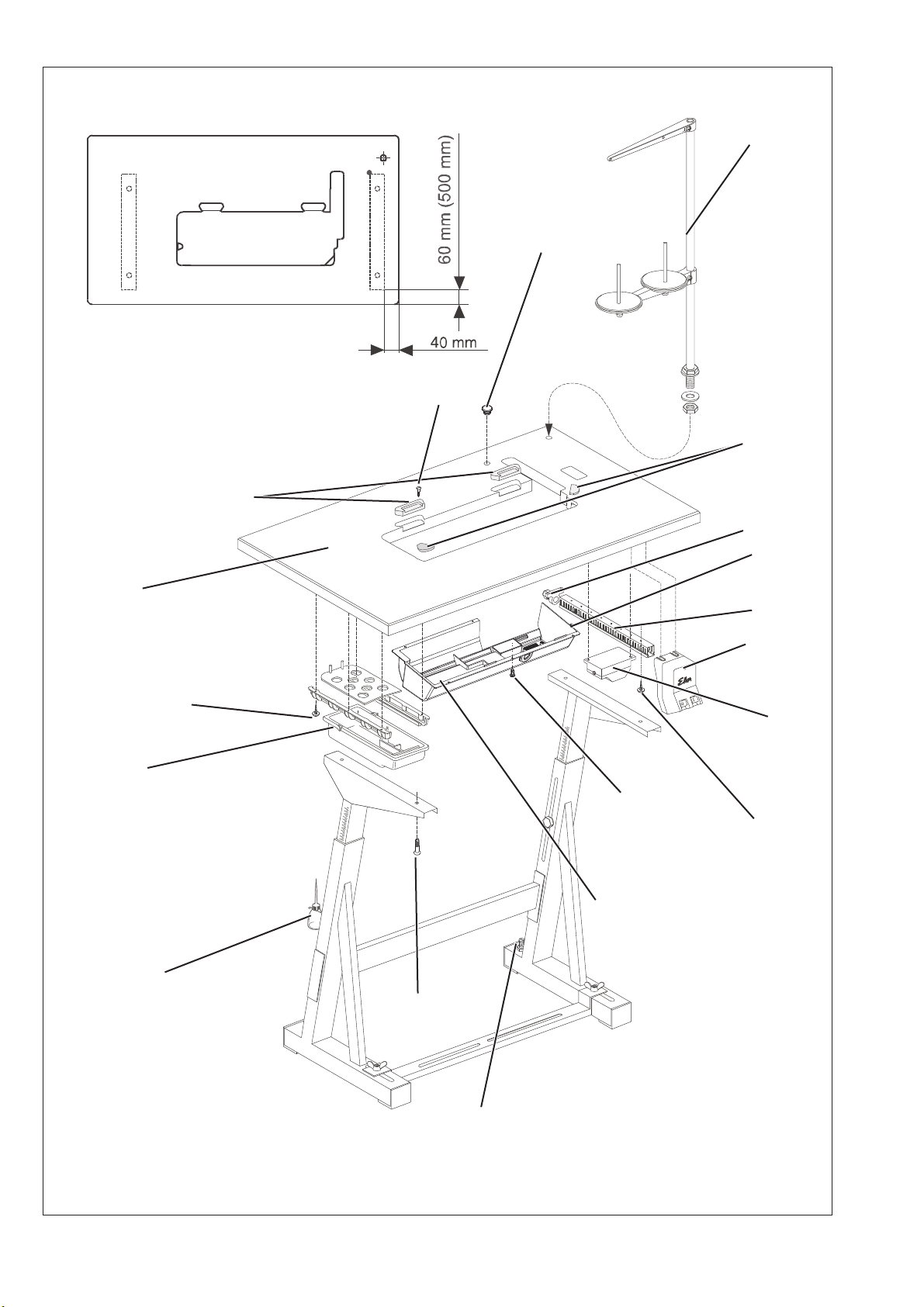
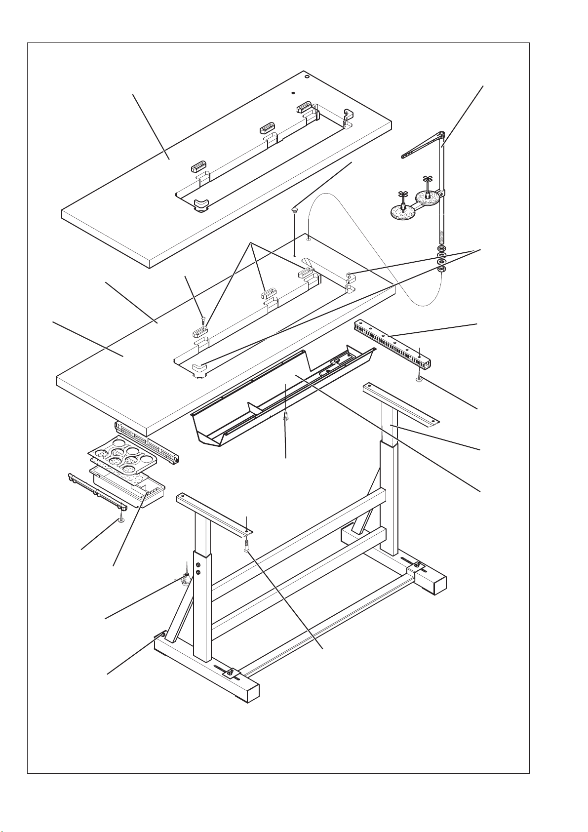
3. Assembling the stand
3.1 Assembling the stand components
–
Assemble the individual stand components as shown in the illustration.
–
Adjust the set screws 8 to insure the stability of the stand.
Make sure that the stand is safe by insuring that every single foot
of the stand touches the ground.
3.2 Assembling the table plate
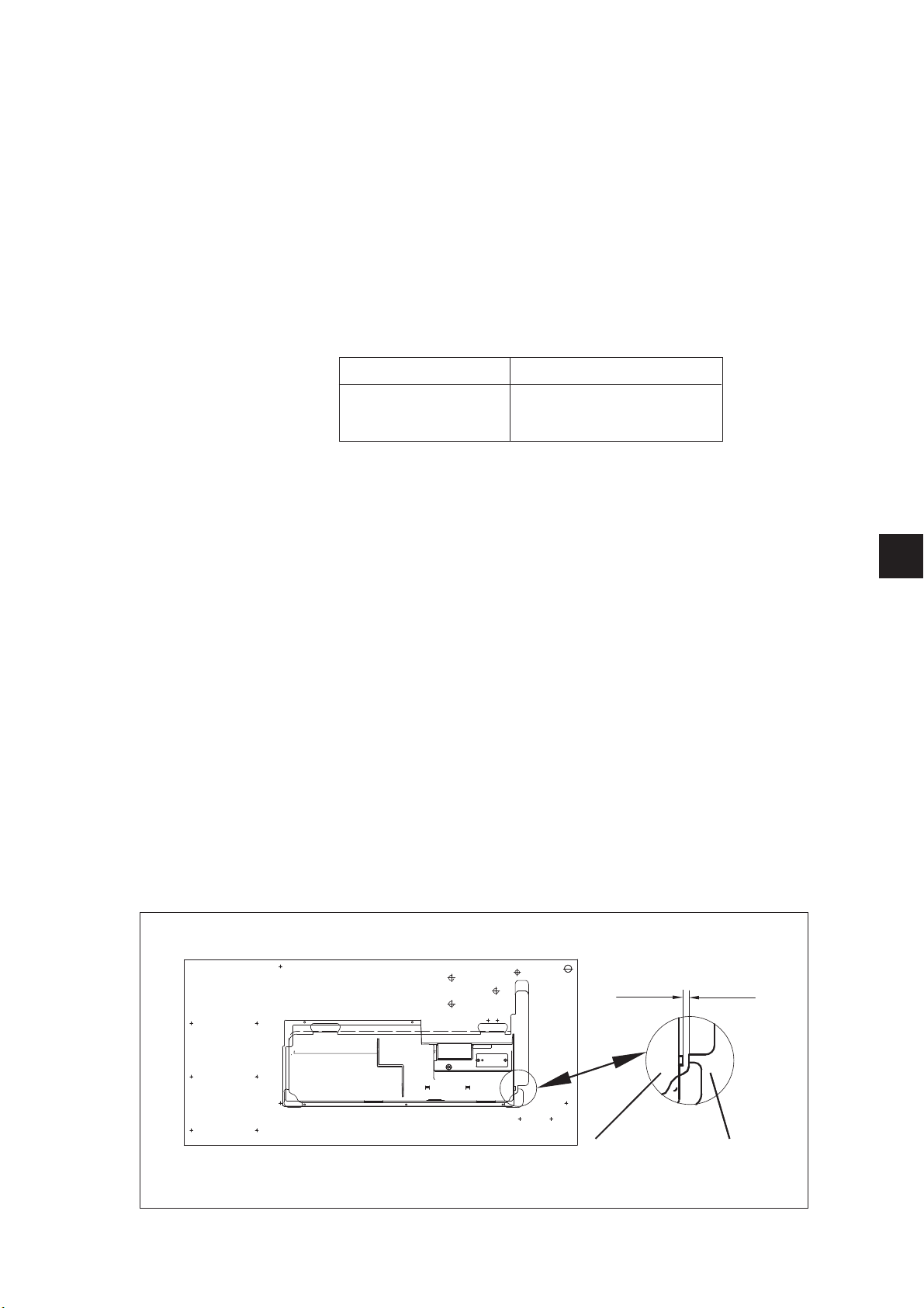
3.2.1 Machines without edge cutter
(867-190020, 867-190040, 867-290020, 867-290040, 867-190322,
867-190342, 867-190345, 867-290322, 867-290342, 867-290345)
In order to have an optimal arrangement of the components, follow the layout.
Stand Layout
MG55 400304 0791 867710
MG55 400314 0791 867711
–
Screw the drawer 10 with its holders onto the left side underneath
thetableplate.
–
Screw the oil sump 7 under the table plate.
With sewing machine equipped with direct drive, all the three stops
should lie against the table opening.
With sewing machine equipped with the drive mounted under the table,
the stop 14 must have 9 mm distance from the table top opening.
–
Screw the main switch 5* to the right side under the table plate.
–
Screw the cable duct 4* behind the main switch 5 under the table plate.
–
Screw the holder 3 for the traction relief of the connecting cable
behind cable duct 4 under the table plate.
–
Screw the sewing-lamp transformer 6 (optional equipment) under
thetableplate.
–
Put the cap 13 into the bore hole of the table plate.
–
Place the hinge bottoms 12 for the machine head into the cutout
of the table plate 9 and tighten the screws.
–
Insert the rubber corner 2.
–
Attach the tabl e p lat e 11 to the stand with woodscrews (B8 x 35)
(see sketch for position).
–
Insert the reel stand 1 in the hole in the table plate and secure it with the
nuts and washers. Fit and align the yarn-reel and unwinding holders. The
yarn-reel holder and the unwinding arm must be vertically in line.
–
Screw the holder for the oil-can 9 onto the left-hand stand brace.
* Not applicable with sewing machines with direct drive.
GB
oil sump table plate
DRIVE UNDER THE TABLE
9mm
7
MG58 400414
1
5
MG58 400404
11
12
2
4,5x15 (x 6)
4
3,5x17 (x 2)
6
3,9x15 (x 11)
7
3,5x17 (x 6)
8
10
9
B8x35 (x 4)
8

3.3 Assembling the stand components (Long arm)
–
Assemble the individual stand components as shown in the
illustration.
–
Adjust the set screws 8 to insure the stability of the stand.
Make sure that the stand is safe by insuring that every single foot
of the stand touches the ground.
3.2 Assembling the table plate
(867-190040-70, 867-190342-70*, 867-290040-70, 867-392242-70*)
In order to have an optimal arrangement of the components,
please follow the layout.
Stand Layout
MG58 400414 0791 867716
MG58 400404 0791 867715
–
Screw the drawer 10 with its holders onto the left side underneath
thetableplate.
–
Screw the oil sump 7 under the table plate.
–
Put the cap 5 into the bore hole of the table plate.
–
Screw the cable duct 4
–
Place the hinge bottoms 12 for the machine head into the cutout
of the table plate and tighten the screws.
–
Insert the rubber corner 2.
–
Attach the tabl e p lat e 11 to the stand with woodscrews (see sketch
for position).
–
Insert the reel stand 1 in the hole in the table plate and secure it
with the nuts and washers.
Fit and align the yarn-reel and unwinding holders.
The yarn-reel holder and the unwinding arm must be vertically in
line.
–
Screw the holder for the oil-can 9 onto the left-hand stand brace.
* MG58 400414 only available for the above-quoted underclass.
#
Not applicable with sewing machines with direct drive.
#
under the table plate.
GB
9

3.5 Setting the working height
1
1
–
The working height is adjustable between 750 and 900 mm
(measured to the upper edge of the table plate).
–
Undo screws 1 on the stand braces.
–
Adjust the table plate horizontally to the required working height.
To prevent tilting, pull the table plate out or push it in by the same
distance on both sides.
–
Tighten both screws 1.
10

4. Sewing drives
4.1 Drive category, type and use
The following sewing drives are available:
Subclass Clutch motor Clutch- DC-positioning drive
positioning drive positioning drive
867-190020 FIR 1147-F.752.3 * Efka VD552/6F82FA Efka DC1600/DA82GA
867-190040 FIR 1148.552.3 *1 Efka DC1550/DA321G
867-290020
867-290040
867-392342 Efka DC1600/DA82GA
867-393342 Efka DC1550/DA321G
867-394342
867-190122 Efka DC1600/DA82GA
867-190142 Efka DC1550/DA321G
867-190322
867-190342
867-190145
867-190445
867-290445 Efka DC1550/DA321G
867-290322 Efka DC1600/DA82GA
867-290342 Efka DC1550/DA321G
GB
867-190040-70 Efka VD552/6F82FA Efka DC1600/DA82GA
867-290040-70 *1 Efka DC1550/DA321G
867-190342-70 Efka DC1600/DA82GA
867-290342-70 Efka DC1550/DA321G
* This clutch motor incorporates an electromagnetic brake that rapidly
stops the rotor when it runs on after the motor has been switched off.
This prevents the sewing machine from starting up unintentionally if
the pedal is operated shortly after switching off.
*1 only for machines with the drive under the table
11

4.2 Fitting the sewing drive
8
7
1
6
5
4.3 Fitting the pedal
2
3
4
–
Attach the sewing drive 2 with its base 1 on the underside of the
table plate.
By screwing the three hexagonal screws (M8x35) with washers
into the table-plate nuts 8.
–
Attach the pedal 4 to the stand brace 3.
–
For ergonomic reasons align the pedal 4 as follows:
The center of the pedal must be approximately under the needle.
There are slots in the stand brace 3 to help align the pedal.
–
Screw the ball pins from the middle to the front hole in the lever 7.
–
Attach pedal linkage 5.
–
Slightly undo screw 6.
–
Adjust the height of the pedal linkage 5 as follows:
when released the pedal 4 should be at an angle of about 10°.
–
Tighten screw 6.
4
12

4.4 Fitting the sewing-drive control for machines with direct drive
8
7
2
6
1
3
–
–
4.5 Fitting the set value initiator
–
–
4
5
Fix the sewing-drive control 1 with 4 screws underneath the table
plate 8.
Fix the power supply cable of the sewing-drive control with the
traction relief clip underneath the table plate.
Screw angle 7 under the table plate 8.
Screw the set value initiator 2 onto the angle 7.
GB
13

4.6 Fitting the pedal
–
Attach the pedal 5 to the stand brace 4
–
For ergonomic reasons align the pedal 5 as follows:
The center of the pedal must be approximately under the needle.
There are slots in the stand brace 4 to help align the pedal.
–
Screw the ball pins from the middle to the front hole in the lever 7.
–
Hinge the pedal linkage 3 with the ball sockets on the s et value
initiator 2 and into the pedal 5.
–
Loosen screw 6.
–
Adjust the height of the pedal linkage 5 as follows:
when released the pedal 4 should be at an angle of about 10°.
–
Tighten screw 6.
14

5. Assembling the machine head
5.1 Fitting the machine head
1
–
Fit the machine head 1 into the opening in the table plate.
5.2 Fitting the oil suction tube
521
–
Unscrew the cover 1 from off the oil sump 2.
–
Put the end of the suction tube 3 into the cover 1.
–
Screw the cover 1 back onto the oil sump.
GB
34
15

21
3
54
7
64
8
16

5.3 Fitting and tensioning the V-belt
Remove protective devices
–
Remove the handwheel 2.
–
Remove the belt guard 1 on the machine head.
–
Remove the cover of the belt guard 3 on the sewing drive.
Fit the V-belt and reinstall the protective devices
–
Attach the belt pulley 5 (in the accessory pack) onto the
sewing-drive shaft.
–
Place the V-belt 4 on the belt pulley of the machine head.
–
Pass the V-belt 4 down through the opening in the table plate.
–
Fold back the upper part of the sewing machine.
–
Place the V-belt 4 on the belt pulley 5 of the sewing drive.
–
Return the upper part of the sewing machine to its original position.
–
Fit the belt guard 1 to the machine head.
–
Replace the handwheel 2.
Tension the V-belt
–
Undo screws 7 on the base of the sewing drive.
–
Tension the V-belt 4 by swivelling the sewing drive.
When the belt is correctly tensioned it must be possible to depress
it by about 10 mm by gently pressing on it with a finger at its
mid-point.
–
Tighten screws 7.
GB
Fit the belt guard to the sew ing drive
–
Adjust the anti-throw protectors 8 (either the cams or the brackets
are adjustable, depending on the drive type) of the belt guard 3 as
follows:
The V-belt 4 must remain on the belt pulleys when the upper part of
the sewing machine is folded back.
See the motor manufacturers’ operating manuals.
–
Screw on the belt-guard cover 3.
17

5.4 Attaching the knee lever
3
1
2
2
The knee lever 2 mechanically raises the sewing foot.
–
Attach the knee lever 2.
–
Undo the screws on the joint 1.
–
Adjust the knee lever s o that it can be conveniently operated with
the right knee.
–
Tighten the screws on joint 1 again.
–
Undo screw 3.
–
Align the knee-pad.
–
Tighten screw 3 again.
Caution !
The knee lever 6 must be detached before the machine head is folded
back.
18

5.5 Fitting the operating panel
43 1
–
Unscrew the thread guide 2 from off the sewing machine head.
–
Fix the control panel fixing angle 1 together with the thread
guide 2.
–
Lift off the arm cover 3 and the valve cap 4.
–
Lay the power supply cable 5 of the operating panel:
along the arm and down through the opening in the table plate 6
or
down through the arm and the base plate - and secure it.
–
Insert the connection plug into the B776 socket of the drive c ontrol.
–
Replace the arm cover 3.
–
Replace the valve cap 4.
5.6 Fitting the sewing lamp (optional equipment)
Caution !
Turning off the main switch does not turn off the current to
the sewing lamp.
Remove the mains plug before connecting.
65
GB
19

43 1
65
7
The sewing lamp can be mounted on the operating-panel bracket if
present.
–
Stick the safety warning label on the front of the main switch 7.
–
Fix the sewing light on the holder 2.
–
Lift off the arm cover 3 and the valve cap 4.
–
Lay the power supply cable in the cutout of the machine arm.
–
Pass the power supply cable down through the hole in the table
plate or the arm and the base plate.
–
Attach the transformer 8 under the table plate with chipboard
screws.
–
Attach the power supply cable under the table plate with cable ties.
–
Plug in the sewing-light transformer lead.
–
Fit the arm cover 1 and valve cap 4.
8
20

6. Electrical connection
6.1 General
Caution !
All work on the electrical equipment of this special sewing
machine may only be carried out by qualified electricians or
other appropriately trained persons.
The mains plug must be removed.
6.2 Checking the mains voltage
Caution !
The mains voltage must coincide with the rated voltage specified
on the model-identification plate.
6.3 Connecting the sewing drive
6.3.1 Connecting the clutch motor
–
Lay the connection cable from the main switch through the cable
conduit to the sewing drive and connect it to the sewing drive. See
connection diagram 9800 169002 B (in the connection pack) or the
circuit diagram on the clutch motor.
–
Lay the mains cable from the main switch back through the cable
conduit and attach to the mains-lead cleat.
6.3.2 Connecting the coupling-positioning actuator
–
Lay the c onnection cable from the motor-protection switch through
the cable conduit to the sewing drive and connect it to the sewing
drive.
See connection diagram 9800 129002 B (in the connection pack) or
the circuit diagram on the coupling-positioning actuator.
–
Lay the mains cable from the main switch back through the cable
conduit and attach to the mains-lead cleat.
–
Plug the cable from the set-point generator into socket b80 of the
drive control. See figure page 20.
6.3.3 Connecting the direct-current positioning actuator
GB
–
Lay the connection cable from the main switch through the cable
conduit to the sewing drive and connect it to the sewing drive. See
connection diagram 9800 139001 B (in the connection pack).
–
Lay the mains cable from the main switch back through the cable
conduit and attach to the mains-lead cleat.
–
Plug the lead from the set-point generator into socket b80 of the
drive control. See figure page 20.
21

6.4 Earthing
1
Illustration!!!!!!!!!
The earthing cable 1 is in the machine’s accessory pack.
The earthing cable 1 takes static charges from the machine head to
earth via the motor base.
–
Connect the earthing cable 1 to the flat plug 2 (already screwed on
the machine head) and lay it through the cable duct to the motor
base.
–
Screw the earthing cable 1 onto the motor base at the point
provided.
–
Attach the earthing cable 1 under the table plate with the nail
clamps.
Caution!
Please make sure that the earthing cable 1 does not touch
the drive belt.
Hint
You do not need to care for the earthing with machines having the
sewing motor fit onto the machine head, since it is already established
through the fitted motor.
22

6.5 Connecting the sewing drive to the mains
B 7 7 6
V 8 . .
B 1 8
L S M . . .
B 2
M
B 8 0
E B . . .
B 4 1
M
A
Caution:
The sewing machine must be connected to the mains with a plug.
Clutch motors and coupling-positioning actuators must be
connected toa3x380-415V 50/60 Hz or 3 x 220 - 240V 50/60 Hz
three-phase supply (see tables in section 4.1).
Connection takes place in accordance with connection diagram
9800 169002 B or 9800 129002 B.
The direct-current positioning actuator is operated with a
single-phase alternating current of 190 - 240V 50/60 Hz. Connection
takes place in accordance with connection diagram 9800 139001 B.
If it is connected to a three-phase supply of 3 x 380V, 3 x 400V or
3 x 415V the sewing drive is connected to one phase and the neutral
conductor.
If the mains supply is three-phase 3 x 200V, 3 x 220V, 3 x 230V or 3 x
240V the sewing drive is connected to two phases.
If a number of direct-current positioning actuators are connected to a
three-phase mains supply they should be equally distributed over all
phases to avoid overloading any one of them.
6.6 Drive-control connection sockets
DA321G control
GB
6F82FA control
DA82GA control
23

6.7 Fitting the proximity switch
–
–
21
Push the proximity switch 2 onto the handwheel flange so that the
retaining pin 1 on the belt guard engages in its groove.
Secure the proximity switch with the two screws.
6.8 Connecting the machine head
Connections
–
The 9870 367004 or 9870 867000 cable is plugged onto the
9850 867000 distributor in the upper part and passed down inside
the upper part.
–
Plug the 37-pole plug of the cable into socket A of the sewing drive
and secure with the screw.
24

6.9 Direction of rotation of sewing drive
Caution:
Before the special sewing machine is started it is essential to
check the direction of rotation of the motor.
Switching it o n can cause damage if the direction of rotation is
incorrect.
GB
6.9.1 Checking the direction of rotation of the clutch motors (mounted under the table)
The direction of rotation of the clutch motor (three-phase motor)
depends on its connection to the three-phase supply. The direction of
rotation must be checked before use. Proceed as follows:
–
Connect the clutch motor and earthing and connect the sewing
drivetothemains.
(see sections 6.3.1, 6.4 and 6.5).
–
Turn on the main switch.
–
Operate the pedal (or the motor’s clutch lever) until the belt pulley
turns.
–
The belt pulley must turn anti-clockwise (looking at the belt pulley).
6.9.2 Changing the direction of rotation of the clutch motors (mounted under the table)
If the sewing drive rotates the wrong way, the phases on the terminals
of the mains connection of the sewing drive 2 must be reversed. This is
done as follows:
–
Turn off the main switch and remove the mains plug.
–
Reverse two of the three phase conductors in the mains plug.
–
Insert the mains plug and turn on the main switch.
–
Check the direction of rotation (see section 6.9.1).
25

6.9.3 Checking the direction of rotation with the direct-current positioning actuator
The direction of rotation of the direct-current positioning actuator is
factory-set to right-to-left by entering the value 1 in parameter F-161.
Even so, the first commissioning stage must be to check the direction
of rotation. Proceed as follows:
–
The proximity switch must be fitted. See section 6.7.
–
The plugs of the s et-point generator, commutation switch, proximity
switch and operating panel must be plugged in. See figure page 23.
–
Do not plug in the 37-pole plug of the sewing machine.
–
Turn on the main switch.
The operating panel displays “Info A5", which means that no valid
Autoselect resistance is recognized and the maximum rotation
speed is therefore limited.
–
Push the pedal slightly forward; the drive rotates; check the
direction of rotation.
–
Replace the 37-pole plug of the machine head.
6.9.4 Changing the direction of rotation with the direct-current positioning actuator
If the sewing drive rotates the wrong way, technician-level parameter
F-161 must be set to the value 1.
Caution !
After a change in the direction of rotation the positions
must be reset.
6.9.5 Adjusting the positions with the VD552/6F82FA coupling-positioning actuator
General
The proximity switch contains an inner disc (generator disc) with
increments for regulating the rotation speed, a center, adjustable
disc 1 for position 1 and an outer, adjustable disc 2 for position 2.
Caution !
Exercise extreme care when adjusting the position discs .
Caution: danger of injury
Please ensure that the position discs and the generator
disc (the innermost disc) are not damaged.
26
1
2

6.10 Setting machine-specific parameters
6.10.1 General
The functions of the sewing-drive control are determined by the
program and the parameter settings.
All parameter values for the relevant machine class and subclass are
pre-set by EFKA prior to delivery of the sewing drives. For each class
and subclass some parameters at technician and manufacturer level
must be changed so that the control is perfectly coordinated with the
machine. The parameters concerned are listed in the table below and
in the parameter sheet (in the accessory pack).
6.10.2 Autoselect
The control “recognizes” which machine series is connected by
measuring the Autoselect resistance in the machine. Autoselect
selects control functions and the pre-set parameter values. If the
control fails to recognize a valid Autoselect resistance (or any at all),
the drive runs only with the so-called emergency operating functions to
prevent machine damage.
See the “EFKA DA82GA” or “EFKA 6F82FA” operating manual.
GB
27

6.11 Connecting the sewing light transformer (optional equipment)
6.11.1 Attaching and connecting the sewing light transformer (optional equipment)
21
–
Remove the machine’s mains plug.
–
Pass the mains cable 1 of the sewing-lamp transformer through the
cable conduit 2 to the main switch.
–
It is connected to the mains-connection side of the main switch (or
motor-protection switch). See connection diagram 9800 169002 B,
9800 129002 B or 9800 139001 B.
–
Stick the adhesive label with the safety instruction on the front of
themainswitch .
–
If the sewing-lamp transformer is connected toa3x380-415V
three-phase supply it must have a neutral conductor.
Caution !
The sewing-light transformer is directly connected to the mains.
It is therefore live even when the main switch is switched off.
The mains plug must be removed before carrying out any work
on the sewing-light transformer, e.g. changing the fuse.
28

6.11.2 Connection to the DA321G
26 5 1
–
Loosen the 4 screws on the front plate of the controls.
–
Remove the front plate.
–
Push the cable from the back through the cable duct 1 into the
controls.
–
Remove the black rubber grommet 2.
–
Push through the round opening of the rubber grommet with a
screwdriver.
–
Guide the cable of the sewing light transformer through the
resulting opening in the r ubber grommet.
–
Insert the rubber grommet again.
–
With a small screwdriver press on the terminal openings 4 and 3 to
open the terminals 5 and 6.
–
Connect the blue cable to terminal 6 and the brown cable to
terminal 5.
–
Fasten the front plate with the 4 screws again.
654 3
GB
29

6.12 Connecting the direct drive
6.12.1 Connecting the Hall-effect sensor (Optional Equipment)
Only with DC 1550 drive:
Motor mounted under the table
·
Gear reduction motor - machine 1,55:1
·
Attention !
Turn off the main switch.
Connect the Hall-effect sensor with the sewing machine switched off.
–
Fit the Hall-effect sensor 1 onto the machine head.
43
21
–
Check whether a magnet is fitted into the belt pulley 2 of the
machine. The magnet is positioned on the inner side of the belt
pulley towards the machine.
–
If no magnet is fitted into the belt pulley 2, it must be exchanged.
If the belt pulley is fitted correctly, the magnet must be positioned
above the Hall-effect sensor, when the tip of the needle penetrates
into the throat plate.
30

–
B 7 7 6
V 8 . .
B 1 8
L S M . . .
B 2
M
B 8 0
E B . . .
B 4 1
M
A
Connect the 9-pole SuB-D plug of the Hall-effect sensor to the
bushing “B18" (IPG / HSM / LSM) of the Efka control drive DA321G.
–
Set the correct machine class with parameter F-290 according to
the corresponding parameter sheet 9800 331104 PBXX.
–
In order to position the machine correctly and to optimize all
functions the following parameters must still be set:
Parameter F-111: set to 3.000 rpm or less.
Parameter F-270: setto6(selectionaccordingtothepositionsensor)
Parameter F-272: canbecalculatedaccordingtotheformulabelow:
Motor pulley diameter (teeth)
x 1000
Machine pulley diameter (teeth)
Inserted needle: up to a thickness of 160.
–
The correct machine class must be set with parameter F-290.
In order to do so, consult the corresponding parameter
sheet 9800 331104 PBXX.
Due to the gear reduction of 1,55:1 the maximum possible speed
is 3.000 rpm.
Due to the new transmission ratio of 1,55:1 a higher torque and a
higher penetration force of the needle of about 30% above a
transmission rate of 1:1 is achieved.
In order to achieve an even higher penetration force, the parameter
F-225 can be set from value “0" to value ”1".
It may happen, that the motor produces a snarling noise.
If this is the c ase, the toothed belt between motor and machine must
be tightened.
GB
31

6.14.5 Connecting the DA321G control
B 7 7 6
V 8 . .
B 1 8
L S M . . .
B 2
M
B 8 0
E B . . .
B 4 1
M
A
21
–
Insert the lead from the controller (pedal) into socket B80 of the
controls.
–
Insert the lead from the motor sensor 1 into socket B2 of the
controls.
–
Insert the lead 2 from the motor into socket B41 of the controls.
–
Insert the lead to the sewing machine into socket A of the controls.
–
Lay all leads through the cable duct.
–
Insert the lead from the control panel (if present) into socket B776.
32

Notes:
GB
33

2
4
6
8
10
1
2
3
4
5
34
6
7

7. Pneumatic connection
Caution:
The pneumatic units will only operate properly at a supply
pressure of 8 to 10 bar. The special sewing machine’s
operating pressure is 6 bar.
Pneumatic-connection pack
A pneumatic-connection pack for stands with compressed-air
maintenance units is available (Order no. 0797 003031).
It contains the following components:
- Connection hose, 5 m long (Ø = 9 mm)
- Hose nozzles and ties
- Plug-and-socket connector
Connecting the compressed-air maintenance unit
–
Attach the compressed-air maintenance unit 1 with bracket, screws
and strap to the stand-brace.
–
Connect the unit to the compressed-air supply with the connection
hose 4 (Ø = 9 mm) and connector R1/4".
GB
7.1 Pneumatic sewing foot lifting
Connecting the compressed-air maintenance unit to the upper
part of the sewing machine
–
Unscrew and remove the c over 6.
–
Connect the hose 3 (in the accessory pack) to the distributor plate
on the machine head.
–
Replace the cover 6.
Adjusting the operating pressure
The operating pressure is 6 bar.
It can be read off at the pressure gauge 4.
–
To adjust the operating pressure raise and turn handle 2:
Clockwise to increase the pressure
Anticlockwise to r educe the pressure.
–
Press the handle 2.
See Instructions 0791 867704.
35

8. Lubrication
1
2
3
Caution: danger of injury !
Oil can cause skin eruptions.
Avoid protracted contact with the skin.
In the event of contact, thoroughly wash the affected area.
CAUTION !
The handling and disposal of mineral oils is subject to legal regulation.
Deliver used oil to an authorised collection point.
Protect your environment.
Take care not to spill oil.
To lubricate the special sewing machine use only DA-10 lubricating oil
or an equivalent oil of the following specification:
–
Viscosity at 40° C : 10 mm
–
Flashpoint: 150 °C
DA-10 is available from DÜRKOPP ADLER AG retail outlets under the
following part numbers:
250 ml container: 9047 000011
1-litre container: 9047 000012
2-litre container: 9047 000013
5-litre container: 9047 000014
Lubricating the machine head (first filling)
NB:
All wicks and felts are saturated with oil prior to delivery. This oil is
returned to the oil reservoir 1, which should therefore not be overfilled.
–
Top up the oil reservoir 1 through the hole 2 to the “max.”mark3.
2
/s
36

9. Sewing test
A sewing test must be carried out when setting-up is complete.
–
Insert the mains plug.
Caution: danger of injury !
Turn off the main switch.
The needle and looper threads may only be threaded with the
sewing machine switched off.
–
Thread the bobbin-winder thread (see operating instructions).
–
Turn on the main switch.
–
Lock the sewing feet in the up position (see operating instructions).
–
Fill the bobbin at low speed.
–
Turn off the main switch.
–
Thread the needle and looper threads (see operating instructions).
–
Select the material to be processed.
–
Carry out the sewing test, first at low speed and then gradually
increasing it.
–
Check that the seams are of the requisite quality.
If not, alter the thread tensioners (see operating instructions).
If necessary the settings given in the servicing instructions should
also be checked and corrected
GB
37

Notes:
38
 Loading...