

Page 1

Contents Page:
Preface and General Safety Information
Part 1: Operating Instructions Class 841-27
1. Product Description
1.1. Proper Use . . . . . . . . . . . . . . . . . . . . . . . . . . . . . . . . . . . . . . . . . . . . . . . . . 5
1.2 Short Description . . . . . . . . . . . . . . . . . . . . . . . . . . . . . . . . . . . . . . . . . . . . . 5
1.2.1 Sewing Machine Head . . . . . . . . . . . . . . . . . . . . . . . . . . . . . . . . . . . . . . . . . . . 5
1.2.2 Feed Unit . . . . . . . . . . . . . . . . . . . . . . . . . . . . . . . . . . . . . . . . . . . . . . . . . . 6
1.2.3 New DÜRKOPP-ADLER-Controls (DAC) . . . . . . . . . . . . . . . . . . . . . . . . . . . . . . . . 6
1.3 Optional Equipment . . . . . . . . . . . . . . . . . . . . . . . . . . . . . . . . . . . . . . . . . . . . 6
2. Technical Data
3. Switching On/Off
3.1 Switching On . . . . . . . . . . . . . . . . . . . . . . . . . . . . . . . . . . . . . . . . . . . . . . . . 8
3.2 Switching Off . . . . . . . . . . . . . . . . . . . . . . . . . . . . . . . . . . . . . . . . . . . . . . . . 8
4. Operating the Sewing Machine Head
4.1 Threading the Needle Thread . . . . . . . . . . . . . . . . . . . . . . . . . . . . . . . . . . . . . . 9
4.2 Winding the Underthread . . . . . . . . . . . . . . . . . . . . . . . . . . . . . . . . . . . . . . . . . 10
4.3 Inserting the Bobbin . . . . . . . . . . . . . . . . . . . . . . . . . . . . . . . . . . . . . . . . . . . . 10
4.4 Changing the Needle . . . . . . . . . . . . . . . . . . . . . . . . . . . . . . . . . . . . . . . . . . . 12
4.5 Regulating Sewing Arch Pressure . . . . . . . . . . . . . . . . . . . . . . . . . . . . . . . . . . . . 12
4.6 Setting the Buttonhole Length . . . . . . . . . . . . . . . . . . . . . . . . . . . . . . . . . . . . . . 13
4.7 Setting the Number of Stitches . . . . . . . . . . . . . . . . . . . . . . . . . . . . . . . . . . . . . . 14
4.8 Replacing and Setting the Knife . . . . . . . . . . . . . . . . . . . . . . . . . . . . . . . . . . . . . 15
4.9 Replacing and Setting the Knife (Cutting Block) . . . . . . . . . . . . . . . . . . . . . . . . . . . . 17
4.10 Replacing the Plastic Cutting Plate (only with Cutting Block) . . . . . . . . . . . . . . . . . . . . . 18
4.11 Needle Thread Tension . . . . . . . . . . . . . . . . . . . . . . . . . . . . . . . . . . . . . . . . . . 19
5. Feeding and Sewing
5.1 Reference Position - Starting the Sewing Procedure - Voiding the Feed Procedure . . . . . . . . 21
5.1.1 Reference Position . . . . . . . . . . . . . . . . . . . . . . . . . . . . . . . . . . . . . . . . . . . . 21
5.1.2 Selecting a Sewing Program . . . . . . . . . . . . . . . . . . . . . . . . . . . . . . . . . . . . . . . 21
5.1.3 Starting the Sewing Procedure . . . . . . . . . . . . . . . . . . . . . . . . . . . . . . . . . . . . . . 21
5.1.4 Voiding the Feed Procedure . . . . . . . . . . . . . . . . . . . . . . . . . . . . . . . . . . . . . . . 22
5.1.5 Continuing Sewing after Thread Breakage . . . . . . . . . . . . . . . . . . . . . . . . . . . . . . . 22
5.1.6 "No Material under Light Barrier" Display . . . . . . . . . . . . . . . . . . . . . . . . . . . . . . . . 24
5.2 Bobbin Change . . . . . . . . . . . . . . . . . . . . . . . . . . . . . . . . . . . . . . . . . . . . . . 25
5.3 Underthread Bobbin Empty . . . . . . . . . . . . . . . . . . . . . . . . . . . . . . . . . . . . . . . . 25
5.4 Re-sewing of Buttonholes . . . . . . . . . . . . . . . . . . . . . . . . . . . . . . . . . . . . . . . . . 26
5.5 Setting of the Clearance of the Buttonholes to the Positioning Edge . . . . . . . . . . . . . . . . . 27
5.6 Programming the Arrangement of the Buttonholes . . . . . . . . . . . . . . . . . . . . . . . . . . . 27
5.7 Removing Material . . . . . . . . . . . . . . . . . . . . . . . . . . . . . . . . . . . . . . . . . . . . . 27
. . . . . . . . . . . . . . . . . . . . . . . . . . . . . . . . . . . . . . . . . . . . . . 7
1
3
Page 2

Contents Page:
6. Maintenance
6.1 Cleaning and Inspection . . . . . . . . . . . . . . . . . . . . . . . . . . . . . . . . . . . . . . . . . 28
6.2 Lubrication . . . . . . . . . . . . . . . . . . . . . . . . . . . . . . . . . . . . . . . . . . . . . . . . 29
4
Page 3

1. Product Description
1.1 Proper Use
DÜRKOPP ADLER 841-27
The
used for the sewing of light to medium weight material.
Such material is, as a rule, material made up of textile or synthetic
fibers. These materials are used in the garment industry. Generally,
only dry material may be worked with this sewing unit. The material
may not be thicker than
presser foot.
The material may not contain any hard objects because the machine
could otherwise only be operated with eye protection. Such eye
protection is not available at this time. The seam is generally sewn with
sewing yarns of a dimension up to 65/2 Nm (synthetic threads with cotton
covering or synthetic threads). Those wanting to use other threads must
first estimate the dangers arising the refrom and, if necessary, take
appropriate safety measures. This sewing unit may only be installed and
operated in dry and clean premises. If the sewing unit is used on other
premises which are not dry and clean, further measures, which are to be
agreed upon, may be necessary (see EN 60204-31:1999).
We, as a manufacturer of industrial sewing machines, assume that at
least semi-skilled operating personnel will be working on our products
so that all normal operations and, where applicable, their dangers are
presumed to be known.
4 mm
is a sewing unit which can properly be
when pressed together by the lowered
1
1.2 Short Description
1.2.1 Sewing Machine Head
The 841-27 is a sewing unit for the automatic sewing of buttonholes in
shirt and blouse fronts.
Because of the construction of the sewing unit in independent function
modules, such as feed, advancing, sewing station and stacker, a
completely overlapping work procedure is possible.
In the feed unit the fronts (material) are positioned along a stop and at
markers and fixed by a vacuum. After the transfer of the material into
the advancing unit the transport occurs in pre-programmed steps
(buttonhole spacing) to the sewing station. During the sewing of the
buttonholes the advancing unit moves synchronously to the transport
movement of the sewing machine. Then a return to the initial position
and the material is stacked.
–
Double saddle stitch - automatic buttonhole machine with bottom and
top feed.
–
Normal manner of sewing, right side of material (side seen) up
during sewing.
–
Pneumatically-operated cutting system with slot in the needle plate.
–
When the needle thread breaks, the needle thread monitor
interrupts the sewing cycle, the cutting is prevented. Then it is
possible to conduct a repair seam as well as removal of the
material.
–
The underthread quantity is controlled by an underthread counter.
–
Sewing drive via DC motor.
–
Material transport via step motor.
–
Mechanical quick change for the clearance of the buttonholes to
the front edge of the material.
5
Page 4
1.2.2 Feed Unit
The feed unit is prepared for connection to an in-house vacuum unit. A
vacuum distributor with filter is available as optional equipment. It
allows for the attachment of up to 3 sewing units to an in-house
vacuum unit.
If no in-house vacuum unit exists the rotary blower, which is available
as optional equipment, must be ordered. The vacuum performance is
sufficient for 3 sewing units.
1.2.3 New DÜRKOPP-ADLER-Controls (DAC)
The graphical operator guidance occurs exclusively via internationally
understandable symbols.
The various symbols are combined into groups within the menu
structure of the sewing and testing programs.
The simple operation makes possible short training times.
The user has 99 freely-programmable sewing programs and four
sequences which can be called up at his disposal.
Each sequence can be combined in any desired order out of a maximum of
3 buttonhole programs. All programmed buttonholes and sequences can be
saved on a RAM memory card.
The comprehensive MULTITEST testing and error diagnostic system
is integrated in the DAC.
A microcomputer assumes the control tasks, monitors the sewing
process and shows operator errors and malfunctions in the display of
the control panel.
1.3 Optional Equipment
A flexible system of optional equipment allows the sewing unit to be
optimally and economically fitted out for each individual application.
Equipment Material number
Vacuum distributor 0841 597514
Rotary blower 3 x 380-415 V; 50 Hz 9800 810001 1
Rotary blower 3 x 220-240 V; 50 Hz 9800 810001 2
Rotary blower 3 x 220-240 V; 60 Hz 9800 810001 3
Pneumatic connections kit 0797 003031
Halogen sewing light with support 9822 510000
Retrofit kit-block cutting, max. buttonhole length 22 mm 0577 590014
for 0841 E00114 22
Retrofit kit-block cutting, max. buttonhole length 35 mm 0577 590024
for 0841 E00114 35
6
Page 5
2. Technical Data
Machine head: Class 577-1111
Needle system: System 265
(slight ball point)
Needle thickness: [Nm] 70 to 100, Standard 80
Yarns: [Nm] synthetic threads and synthetic threads
with cotton covering up to 65/2
Sewing stitch type: 301/Double saddle stitch
Number of stitches: [min-1] 1000 to 4000
- at delivery 3500
Delivery with 841-E114/22
Number of stitches per seam construct: 91, 120 149
- at delivery 120
Buttonhole length: [mm] max. 22
Buttonhole width: [mm] 4
Incision length: [mm] 6, 8, 10, 12, 14, 16
- at delivery 12
Delivery with 841-E114/35
Number of stitches per seam construct: 127, 149, 173, 223, 261
- at delivery 173
Buttonhole length: [mm] max. 35
Buttonhole width: [mm] 4
Incision length: [mm] 18, 20, 22, 24, 26, 28
- at delivery 20
1
Max. length of the material [mm] 900
Minimum width of the material [mm] 250
Distance between the first and last buttonhole [mm] 650
Clearance between individual buttonholes [mm] 40
Clearance of the buttonhole to the front edge [mm] 10-22
Sewing motor: EFKA DC1600/DA82GL
Nominal rating: [kW] 0,75
Working overpressure: [bar] 6
Air consumption: [NL] approx. 15 per work cycle
Rated voltage: 1~ 190 - 240 V, 50/60 Hz
Electr. connected load [kVA] 1,5
Dimensions: [mm] 2100 x 940 x 1560
Work height: [mm] 930
Weight (without optional equipment): [kg] 290
Specified noise level: Lc dB (A)
7
Page 6
3. Switching On/Off
1
2
3
4
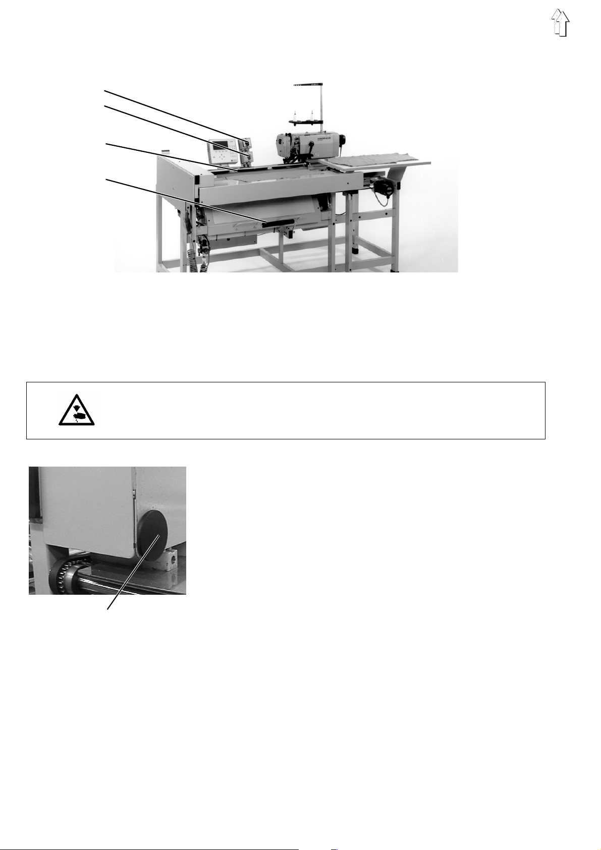
3.1 Switching On
For the operational readiness of the sewing unit the feed rail must be
run into the reference position once after switching on.
The reference position is required in order for the controls to receive a
defined base position for the feed rail.
5
3.2 Switching Off
Caution Risk of Injury !
Do not reach into the motion area of the feed rail 3 during the
reference run.
–
Turn on the switch 1 of the head of the sewing machine.
–
Turn on the main switch 2.
The controls load the machine program.
The DÜRKOPP-ADLER logo appears briefly in the display of the
control panel.
–
The operator is prompted to start the reference run by the
<==== REF
"
–
Operate the start switch 5.
The feed rail runs into its left end position.
–
The screen changes to the main display.
The sewing unit is ready for operation.
–
For switching the rotary blower (optional equipment) on: turn the
switch of the rotary blower to the "I" position.
–
Turn off the main switch 2.
–
Turn off the switch 1 of the head of the sewing machine.
–
The sewing unit is disconnected from the power supply.
It is no longer ready for operation.
–
For switching the rotary blower (optional equipment) off: turn the
switch to the 0 position.
" message.
8
Page 7
4. Operating the Sewing Machine Head
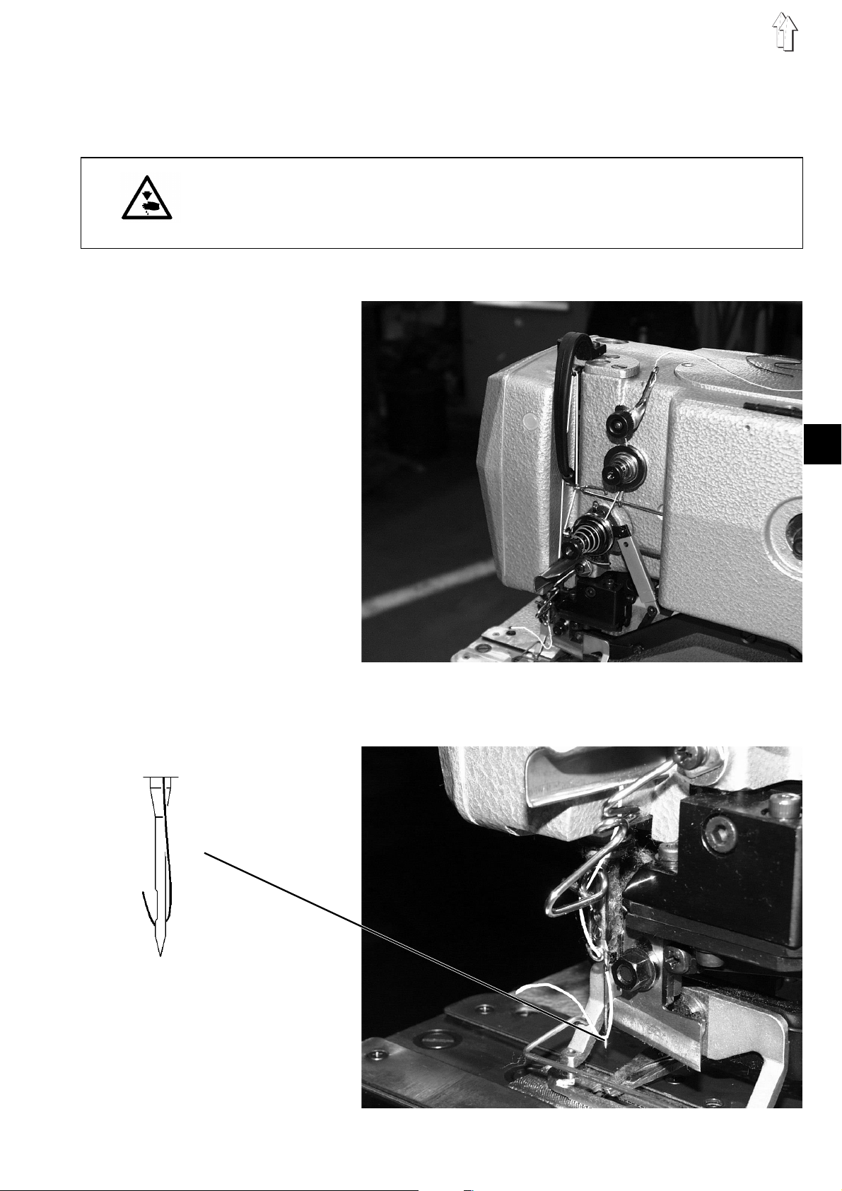
4.1 Threading the Needle Thread
Caution Risk of Injury !
Turn off the main switch 1 of the sewing machine head !
Thread the needle thread only with the machine head turned off.
–
Thread the needle thread as shown in the illustration.
1
9
Page 8
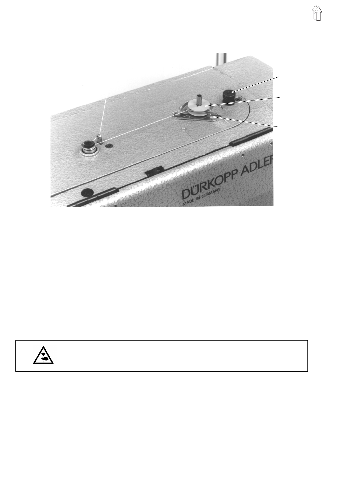
4.2 Winding the Underthread
3
1
2
4.3 Inserting the Bobbin
–
Place the yarn spool on the yarn stand.
–
Thread the underthread as shown in the illustration.
–
Place the bobbin on winder 1.
–
Wind the underthread clockwise approx. 5 times around the bobbin
core.
–
Swing winder lever 2 to the bobbin and let catch.
–
The bobbin is filled during sewing.
The bobbin can also be filled outside the sewing sequence (see
Chapter Bobbin Change)
–
Winder lever 2 ends the winding procedure as soon as the bobbin
is filled.
–
After the winding, tear off the underthread at thread clamp 3.
Caution Risk of Injury !
Turn off switch 1 for the sewing machine head!
The bobbin can only be changed with the machine head turned off!
10
Removing the empty bobbin.
–
Flip bracket 5 up and remove the bobbin case top with bobbin.
–
Remove the empty bobbin from the bobbin case top.
Page 9
5
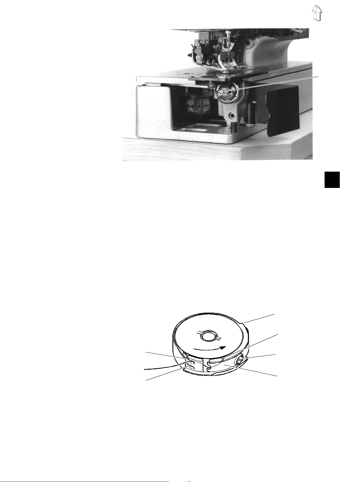
Threading the bobbin
–
Insert a full bobbin into the bobbin case top, the bobbin must
thereby turn counterclockwise when the underthread is pulled off.
–
Guide the underthread through slot 6 under spring 7.
–
Depending on the desired buttonhole, the underthread must be
guided through slot 9 for a
pulled forward over the hook back) or through slot 10 for a
flat-form
–
Cut off the thusly threaded underthread at knife 11.
Setting the underthread tension
–
Set the underthread tension by turning screw 12 so that the bobbin
case slowly lowers under its own weight with the thread end held
tight.
buttonhole (less thread).
raised-form
buttonhole (more thread is
11
6
1
9
12
7
10
Inserting the bobbin case top
–
Place the bobbin case top with bobbin on the bobbin case bottom
taking care that bracket 5 can be heard to catch.
11
Page 10

4.4 Changing the Needle
1
2
Caution Risk of Injury !
Turn off the switch 1 of the sewing machine head.
Change the needle only with the sewing machine head turned off.
–
Loosen screw 1.
–
Remove the needle from the needle bar.
–
Push the new needle into the drilled hole of the needle bar up to
3
the stop.
–
Align the needle so that the furrow 3 lies on the side not facing the
knife.
–
Tighten screw 1.
ATTENTION !
The factory-set clearance of the hook to the needle is set for needles
with a thickness of 80.
After the change to a different needle thickness the clearance must be
corrected (see Service Instructions).
4.5 Regulating Sewing Arch Pressure
The sewing arch pressure should be set to the maximum value. The
sewing arch pressure must only be lowered in case of delicate fabrics.
–
The sewing arch pressure can be regulated at screw 2.
12
Page 11

4.6 Setting the Buttonhole Length
Caution Risk of Injury !
Turn off the switch of the sewing machine head.
Change the buttonhole length only with the sewing machine head
turned off!
2
1
1
–
Turn off the switch for the machine head.
–
Pull off the hand crank 1.
–
Lift lid 2 up to the stop.
–
Loosen screw 3.
–
Adjust lever 4 in the link so that the set buttonhole length results.
–
Tighten screw 3.
–
Unlock support 5 and close lid 2.
–
Attach hand crank 1.
–
Turn on the switch for the machine head.
–
Set the new buttonhole length with the "
function in the "
–
Call up the "
–
Check if the set buttonhole length corresponds with the sewn
buttonhole.
Buttonhole Parameters
One-time Sewing
" menu (1X) and sew a buttonhole.
Buttonhole Length
" menu.
"
5
3
4
13
Page 12

4.7 Setting the Number of Stitches
2
6
Caution Risk of Injury !
Turn off the main switch!
Change the number of stitches only with the machine turned off!
–
Pull off the hand crank .
–
Lift lid 2 up to the stop.
–
Exchange the alternative wheels 6 pair-wise according to the table.
–
Unlock support 5 and close lid 2.
–
Attach hand crank.
–
Turn on the sewing unit.
–
Set the number of stitches to the same value in the "
Parameters
" menu with the "
Number of Stitches
Buttonhole
" function.
5
841 with sewing device 841-E114/22
Number of stitches Number of teeth
upper / lower
91 25 / 54
120 30 / 49
149 34 / 45
841 with sewing device 841-E114/35
Number of stitches Number of teeth
upper / lower
127 31 / 48
149 34 / 45
173 37 / 42
223 42 / 37
261 45 / 34
14
Page 13

4.8 Replacing and Setting the Knife
Caution Risk of Injury !
Turn off the main switch!
The sewing arch must be in the base position otherwise the knife
strikes on the sewing arch!
1
3
1
2
Removing the knife
–
Loosen nut 1.
–
Pull out knife 2.
Attaching the knife
–
Insert a new knife (nut 1 loosened) and first push all the way up.
ATTENTION !
It is essential to take care that there is a clearance of
between the needle thread shears and the lower edge of the knife.
Caution Risk of Injury !
When operating the keys on the controls do not reach into the area of
the knife for any reason.
1 mm min.
–
Tighten the nut.
–
Turn on the switch for the machine head.
–
Turn on the main switch.
–
Press the F2 key when the Dürkopp Adler logo displays.
The menu for the machine-specific setting and test programs
appears.
–
Select the "
Machine Head
" function.
15
Page 14

ATTENTION !
During the use of the setting program do not turn on the handwheel or
the hand crank!
–
If necessary, lower the sewing arch by pressing the
–
With the setting aid still turned on, the knife block can now be
moved downward with the
–
By pressing the F4
If the sewing arch is not lowered the knife block can not be run
downward with the F4
with the F3
blocked with the knife lowered.
Aligning the knife
The front edge of the knife should lay
edge of the needle plate with the knife block lowered.
Setting:
–
Lift the sewing arch.
–
Slightly loosen nut 1.
–
Move the knife.
–
Tighten nut 1.
–
Check the incision depth, if necessary repeat the procedure.
The incision of the knife should lie about 2 fabric threads in front of the
last sewn back tack.
Setting:
–
Loosen screw 3 and set the clearance accordingly.
Observe:
With the knife block lowered there
0.5 mm
plate insert.
–
Tighten screw 3.
key
. Also the function of the
between the front edge of the knife and the slot in the needle
key
key
F4 key
again the knife block can be run up again.
. First the sewing arch must then be lowered
.
F3 key
approx. 2 mm
must
be a safety clearance of
(lift sewing arch) is
F3 key
under the upper
.
Ending the setting aid
–
Press the "F1" key.
The setting program is ended.
16
Page 15

4.9 Replacing and Setting the Knife (Cutting Block)
Caution Risk of Injury !
Turn off the main switch!
The sewing arch must be in the base position otherwise the knife
strikes on the sewing arch!
3
1
2
1
45 4
Removing the knife
–
Loosen nut 1.
–
Pull out knife 2.
Attaching the knife
–
Screw in completely the knife depth stop
–
Insert a new knife (nut 1 loosened) and first push all the way up.
ATTENTION !
It is essential to take care that there is a clearance of
between the needle thread shears and the lower edge of the knife.
Caution Risk of Injury !
When operating the keys on the controls do not reach into the area of
the knife for any reason.
–
Tighten the nut.
–
Turn on the switch for the machine head.
–
Turn on the main switch.
–
Press the F2 key when the Dürkopp Adler logo displays.
The menu for the machine-specific setting and test programs
appears.
–
Select the "
Machine Head
" function.
1 mm min.
17
Page 16

ATTENTION !
During the use of the setting program do not turn on the handwheel or
the hand crank!
–
If necessary, lower the sewing arch by pressing the
–
With the setting aid still turned on the knife block can now be
moved downward with the
–
By pressing the F4
If the sewing arch is not lowered the knife block can not be run
downward with the F4
with the F3
blocked with the knife lowered.
Setting the knife to cut
With the knife block lowered and the knife depth stop screwed
completely in, the knife should lay onto the plastic cutting block.
Setting:
–
Lower the knife block.
–
Slightly loosen nut 1.
–
Press the knife onto the cutting block.
–
Tighten nut 1.
–
Conduct a sewing trial and check the cut, if necessary correct the
cutting depth with the knife stop.
The incision of the knife should lie about 2 fabric threads in front of the
last sewn back tack.
Setting:
–
Loosen screw 3 and set the clearance accordingly.
Observe:
With the knife block lowered there
0.5 mm
plate insert.
–
Tighten screw 3.
key
. Also the function of the
between the front edge of the knife and the slot in the needle
key
key
F4 key
again the knife block can be run up again.
. First the sewing arch must then be lowered
.
F3 key
must
be a safety clearance of
(lift sewing arch) is
F3 key
.
Ending the setting aid
–
Press the "F1" key.
The setting program is ended.
4.10 Replacing the Plastic Cutting Plate (only with Cutting Block)
–
Loosen screws 4.
–
Pry out cutting plate 5 with a screwdriver and remove it.
–
Insert a new cutting plate, press on the holder and tighten the
screws 4.
–
Conduct the setting as per the Chapter " Replacing and Setting the
Knife (Cutting Block)".
18
Page 17

4.11 Needle Thread Tension
At the factory the machine head is set so that buttonholes with
flat-form tacking and raised-form buttonhole seams are sewn.
4
5
6
Pre-tension
The pre-tension 4 is always in effect. It serves to quiet the needle
thread. The setting value should be very small (5-10 g). The
pre-tension 4 has little influence on the seam construct.
Main tension
The main tension 5 is effective when sewing the two buttonhole seams
of the buttonhole. The main tension 5 is open during sewing of the
tacking as well as during thread trimming.
Tacking tension
The tacking tension 6 opens only during thread trimming, otherwise
this tension is closed during the complete sewing procedure.
Buttonhole seam tension
The buttonhole seam tension is mutually generated by the main
tension 5 and tacking tension 6, whereby about 1/3 of the buttonhole
seam tension should be generated by the tacking tension 6.
1
Setting
–
Thread the needle thread so that it does not run through the main
tension 5.
–
Call up the "
One-time Sewing (1X)
" menu and sew a buttonhole.
19
Page 18

–
Set the tacking tension 6 so that, during the sewing procedure, the
greatest possible quantity of needle thread from the yarn spool is
used without the needle thread above the pre-tension fluttering too
much or tearing.
–
Thread the needle thread as per Chapter 4.1 (needle thread
through the main tension).
–
Call up the "
–
Set the main tension 5 so that, during sewing of the buttonhole
seams, a satisfactory seam construct is achieved (uniform
raised-form buttonhole seams).
If the seam quality worsens after a change of thread, a correction
should occur only by turning the main tension 5.
Checking
–
Thread needle thread and underthread of different colors.
–
Conduct a trial seam.
With two-color sewing the color of the needle thread should only be
visible in the tacking of the buttonhole from above.
One-time Sewing (1X)
" menu and sew a buttonhole.
20
Page 19

5. Feeding and Sewing
5.1 Reference Position - Starting the Sewing Procedure - Voiding the Feed Procedure
5.1.1 Reference Position
For the operational readiness of the sewing unit the advancing unit must be
run into the reference position once after switching on.
The reference position is required in order for the controls to receive a defined
base position for the advancing unit.
Caution Risk of Injury !
Do not reach into the motion area of the feed and advancing units during
the reference run.
–
Turn on the main switch.
The controls load the machine program.
The DÜRKOPP-ADLER logo appears briefly in the display of the control panel.
–
The operator is prompted to start the reference run by the display of the
<==== REF
"
–
Operate the start switch.
The advancing unit runs into its left end position.
–
The screen changes to the main display.
The sewing unit is ready for operation.
" message.
1
5.1.2 Selecting a Sewing Program
When the main screen displays, the program sequence can be changed using the ×
and Ø keys. The buttonhole program within the buttonhole sequence can be changed
with the Õ and Ö keys (see also Part 4: Programming Instructions "Main Display").
If a buttonhole sequence is to be changed or newly generated:
–
5.1.3 Starting the Sewing Procedure
Caution Risk of Injury !
When triggering the sewing procedure do not reach into the motion area of
the feed and advancing units.
Dependent on the setting of the "
Parameters menu, the sewing procedure is started in the following manner:
–
–
–
With the main display showing, press the F3 key.
The buttonhole sequence submenu appears.
The buttonhole sequences can be generated and changed here.
(see also Part 4: Programming Instructions "Buttonhole Sequence").
Knee Switch
Starting the sewing process only through
pressing the start key
Press the knee switch. The vacuum is turned on.
Press the start key. The sewing procedure starts.
Starting the sewing process with a delay, using
the knee switch
Press the knee switch.
The vacuum is turned on.
The sewing procedure starts automatically after the defined period.
" parameter in the Global
The sewing process starts after releasing the knee switch
–
Strike the knee switch. The vacuum is turned on.
–
Release the knee switch. The sewing procedure starts.
21
Page 20

5.1.4 Voiding the Feed Procedure
The feed procedure can be voided for making corrections:
–
Strike numeric key "3" on the control panel.
or
if the "
again.
–
The vacuum field is turned off.
5.1.5 Continuing Sewing after Thread Breakage
Knee Switch
1
2
" function is turned on, press the knee switch
When the thread monitor registers a breakage of the needle thread,
the following procedures are triggered :
–
The current buttonhole is completed without thread.
–
The thread breakage symbol appears in the display.
The sewing procedure is interrupted.
–
Select one of the symbols for continuing, which are described
under the points 1, 2 and 3, with the arrow keys "×" and "Ø".
1. Cover-seaming
2. New feed
3. Continuing sewing
Caution Risk of Injury !
Thread the needle thread only with the sewing machine head turned
off.
1. Cover-seaming
–
Strike the enter key or start key.
–
Turn off switch 1 for the sewing machine head.
The symbol for "Secured Stop" appears.
–
Rethread the needle thread.
–
Turn on the switch for the sewing machine head.
The indicator at the left appears.
–
Strike the enter key.
The sewing procedure continues.
22
Page 21

2. New feed
–
Select the symbol at the left with the arrow keys "×" and "Ø ".
–
Strike the enter key.
The advancing device swings to the back.
The indicator at the left appears.
–
Strike the enter key or start key.
The clamping rail opens.
–
Remove the material.
–
Turn off the switch for the sewing machine head.
–
Rethread the needle thread.
–
Turn on the switch for the sewing machine head.
–
Select the the buttonhole at which the sewing procedure should
continue with the arrow keys "Õ" and "Ö".
–
Strike the enter key.
The main menu appears in the display.
The thread breakage symbol appears at the bottom right in order
to indicate that the sewing unit is in the thread breakage mode.
–
To void the thread breakage mode strike key "3".
–
To continue sewing, feed the material again and strike the start key.
The sewing procedure is continued at the desired position.
3. Continuing sewing
–
Select the symbol at the left with the arrow keys "×" and "Ø ".
–
Strike the enter key.
The advancing device runs to the right and the clamping rail
swings.
–
Turn off the switch for the sewing machine head.
–
Rethread the needle thread.
–
Turn on the switch for the sewing machine head.
–
Select the buttonhole at which the sewing procedure should
continue with the arrow keys "Õ" and "Ö".
1
–
Strike the enter key.
A symbol appears on the side.
Eventually adjust the material position.
–
Strike the enter key.
The sewing process will continue from the wished position.
23
Page 22

5.1.6 "No Material under Light Barrier" Display
The light barrier 1 checks if material is present. If no material lies
under the light barrier, the indicator at the left appears in the display.
The indicator can appear under following conditions:
–
The material was displaced.
–
The material has run out.
–
The light barrier is incorrectly set.
–
There is no material under the light barrier.
–
The sewing procedure was started unintentionally.
1
2
3
Removing the material
–
Strike the enter key.
The advancing device runs into the base position.
–
Strike the enter key again.
The clamping rail opens.
–
Remove the material.
Realigning the material
–
When the material is realigned so that the light beam is
interrupted, the display changes so that the symbol at the left
appears.
–
Strike the enter key.
The sewing procedure is continued.
Light barrier
If there is still material lying under the light barrier, the sensitivity of
the light barrier must be altered.
–
Turn adjusting screw 3 clockwise until the LED 2 goes out.
"ESC" key function
Dependent on the display, a different function is triggered with the
"ESC" key than with the enter key.
–
–
The advancing device runs into the base position.
Strike the enter key.
The material can be removed.
The next buttonhole is sewn.
24
Page 23

5.2 Bobbin Change
The specified value (number of button holes) is shown with the
numeric key "2".
–
The symbol at the left appears in the display.
Now a new value can be specified with the numeric keypad.
–
In order to reset the counter for the number of underthread stitches
to the specified or the set value, strike the enter key.
–
To exit leaving the display unchanged, strike the "ESC" key.
Winding the underthread
–
Select the symbol at the left with the arrow keys "×" and "Ø".
–
When this symbol is selected the screen at the left appears.
–
The sewing drive is started with the "F2" key.
–
The sewing drive is stopped with the "F3" key.
–
One returns to the main menu with the "F1" key.
1
5.3 Underthread Bobbin Empty
When the underthread counter has counted down to 0, the following
procedures are triggered:
–
–
–
–
Caution Risk of Injury !
Change the bobbin only with the sewing machine head turned off.
–
–
–
–
When the underthread counter has counted down to 0 during the
sewing of the buttonhole facing, the advancing unit runs into the
right end position.
The "Underthread Bobbin Empty" symbol appears in the display.
The sewing procedure is interrupted.
Turn off switch 1 for the sewing machine head.
The "Secured Stop" symbol appears.
When the underthread bobbin is empty after the sewing of the last
buttonhole on the buttonhole facing, the material is stacked.
Change the bobbin.
Turn on the switch for the sewing machine head.
The indicator at the left appears.
The set underthread capacity is shown.
If the underthread capacity is to be changed, enter the new value with
the numeric keypad and confirm with the enter key.
If the value for the underthread capacity is not to be changed,
strike the enter key.
The sewing procedure is continued.
25
Page 24

5.4 Re-sewing of Buttonholes
Individual buttonholes of a buttonhole facing can be re-sewn with the
Re-sewing of Buttonholes
"
The re-sewing mode can also be turned on during the sewing
procedure.
–
–
–
Sewing procedure with turned-on re-sewing mode
–
–
–
1. Sewing
–
–
" function.
Strike key "5" in the main menu.
The symbol is shown as a negative.
The re-sewing of individual buttonholes is turned on.
To turn off the re-sewing of buttonholes strike key "5" in the main
menu.
The symbol is shown normally. The re-sewing mode is turned off.
After the next stacking procedure the re-sewing mode is turned off
automatically.
Insert material.
Strike the start key.
The sewing procedure is triggered.
The advancing device transports the material up to the first
buttonhole position.
A selection window with the following 4 options appears in the
display : 1. 2. 3. 4.
Select the symbol at the left with the arrow keys "×" and "Ø".
Strike the enter key.
The buttonhole in the current position is sewn.
2. Move on
–
Select the symbol at the left with the arrow keys "×" and "Ø".
–
Select the buttonhole up to which the advancing device should
transport the material with the arrow keys "Õ " and "Ö ".
–
Strike the enter key.
The material is transported to the entered buttonhole position.
3. Complete sewing of the material
–
Select the symbol at the left with the arrow keys "×" and "Ø".
–
Strike the enter key.
All buttonholes as of the current position are re-sewn.
After the sewing procedure the material is stacked.
4. Stacking
–
Select the symbol at the left with the arrow keys "×" and "Ø".
–
The following functions can be selected with the arrow keys "Õ"
and "Ö":
Remove material
Stack material
26
–
Strike the enter key.
Page 25

5.5 Setting of the Clearance of the Buttonholes to the Positioning Edge
1
2
The clearance of the buttonholes to the positioning edge can be set
with the setting wheel 1. The indicator 2 serves as orientation to
quickly see how the clearance is set.
The clearance of the buttonholes to the positioning edge can lie in a
range from 10 to 22 mm.
5.6 Programming the Arrangement of the Buttonholes
The buttonhole arrangement can, with the 841-27, be changed via the
controls. The following parameters can, among others, be altered :
–
Material - men’s shirt or women’s blouse
–
Regular or irregular arrangement of the buttonholes
–
Spacing of the buttonholes
–
Sewing begin
How the settings are made is described in Part 4:Programming
Instructions in the Chapter "Buttonhole Program".
5.7 Removing Material
1
–
Strike key "4" in the main menu.
The symbol is shown as a negative.
The stacker is opened.
–
Remove material.
–
After the next sewing procedure the stacker is automatically closed
again.
27
Page 26

6. Maintenance
6.1 Cleaning and Inspection
1
Caution Risk of Injury !
Turn off the main switch.
The maintenance of the sewing unit may only be conducted
when the machine is turned off.
The maintenance work must occur at the latest as per the
maintenance intervals listed in the tables (see column
Operating Hours).
2
3
Maintenance work
to be conducted
Machine head
Remove sewing dust, thread rests and
cutting residue.
Sewing drive
Check condition of the V-belt.
Pneumatic system
Check and/or set air pressure.
Check water level in the pressure regulator.
Clean the filter insert.
Remarks
Particularly to be cleaned:
- Underside of the needle plate, top of the needle plate
(slider)
- Sewing arch
- Area around the hook
- Bobbin case
- Thread trimmer
- Light barrier
The water level should not rise up to the filter insert 1.
After screwing in the drain screw 3, drain the water out of
the water separator 2 under pressure.
Dirt and condensation are removed through the filter insert
1. Separate the machine from the compressed air supply.
Screw in the drain screw 3. The pneumatic system of the
machine must be pressure-free. Screw off the water
separator 2. Screw off the filter insert 1 and wash out the
dirty filter bowl and filter insert with naphtha (no solvents!)
and blow dry. Reassemble the maintenance unit and attach.
Hours of
Operation
8
160
8
40
500
Check the system for leaks.
Running carriage
Switch cabinet
28
Renew lubrication
Clean the filter mat of the switch cabinet ventilator
500
500
8
Page 27

6.2 Lubrication
Caution Risk of Injury !
Oil can cause skin rashes.
Avoid longer skin contact.
After contact wash yourself thoroughly.
ATTENTION !
The handling and disposal of mineral oils is subject
to legal constraints.
Deliver used oil to an authorized reception point !
Protect your environment.Take care not to spill any oil.
For lubrication use only
ESSO SP-NK 10
lubricating oil or an
equivalent oil with following specification:
–
Viscosity at 40°C: 10 mm
–
Flash point: 150°C
2
/s
1
The oil is available from
following parts no.s:
–
2 liter container: 9047 000013
–
5 liter container: 9047 000014
1
DÜRKOPP ADLER AG
2
sales offices under the
Maintenance work
to be conducted
Hook lubrication
Check the oil level in reservoir 1.
Machine head lubrication
Check the oil level in reservoir 2.
Remarks
Tilt the machine head to the back.
Fill reservoir 1 through the filler opening up to the
with oil.
The oil level should not drop below the
If necessary, fill oil through the drilled hole in the viewing
window up to the
"max"
mark.
"min"
"max"
mark.
Hours of
Operation
8
mark
40
29
 Loading...