

Page 1

Contents Page:
Part 2: Installation Instructions Class 841-27
1. Scope of Delivery of the Sewing Unit
2. Installing the Sewing Unit
2.1 Transport Guards . . . . . . . . . . . . . . . . . . . . . . . . . . . . . . . . . . . . . . . . . . . 4
2.2 Aligning the Sewing Unit . . . . . . . . . . . . . . . . . . . . . . . . . . . . . . . . . . . . . . . 5
2.3 Attaching the Yarn Stand . . . . . . . . . . . . . . . . . . . . . . . . . . . . . . . . . . . . . . . 5
2.4 Connecting the Vacuum . . . . . . . . . . . . . . . . . . . . . . . . . . . . . . . . . . . . . . . . 5
2.5 Checking the V-belt Tension . . . . . . . . . . . . . . . . . . . . . . . . . . . . . . . . . . . . . 6
3. Electrical Connection
3.1 Mounting the Control Panel . . . . . . . . . . . . . . . . . . . . . . . . . . . . . . . . . . . . . . 7
3.2 Checking the Nominal Voltage . . . . . . . . . . . . . . . . . . . . . . . . . . . . . . . . . . . . 8
4. Pneumatic Connection
4.1 Connecting the Compressed Air Maintenance Unit . . . . . . . . . . . . . . . . . . . . . . . . . 9
4.2 Setting the Operating Pressure . . . . . . . . . . . . . . . . . . . . . . . . . . . . . . . . . . . . 10
5. Refilling the oil
5.1 Filling the oil reservoir . . . . . . . . . . . . . . . . . . . . . . . . . . . . . . . . . . . . . . . . . 11
5.2 Lubricating Wicks and Felts . . . . . . . . . . . . . . . . . . . . . . . . . . . . . . . . . . . . . . 12
5.3 Regulating of the Hook Lubrication . . . . . . . . . . . . . . . . . . . . . . . . . . . . . . . . . . 12
. . . . . . . . . . . . . . . . . . . . . . . . . . . . . . . 3
2
6. Commissioning
. . . . . . . . . . . . . . . . . . . . . . . . . . . . . . . . . . . . . . . . . . . . 13
Page 2
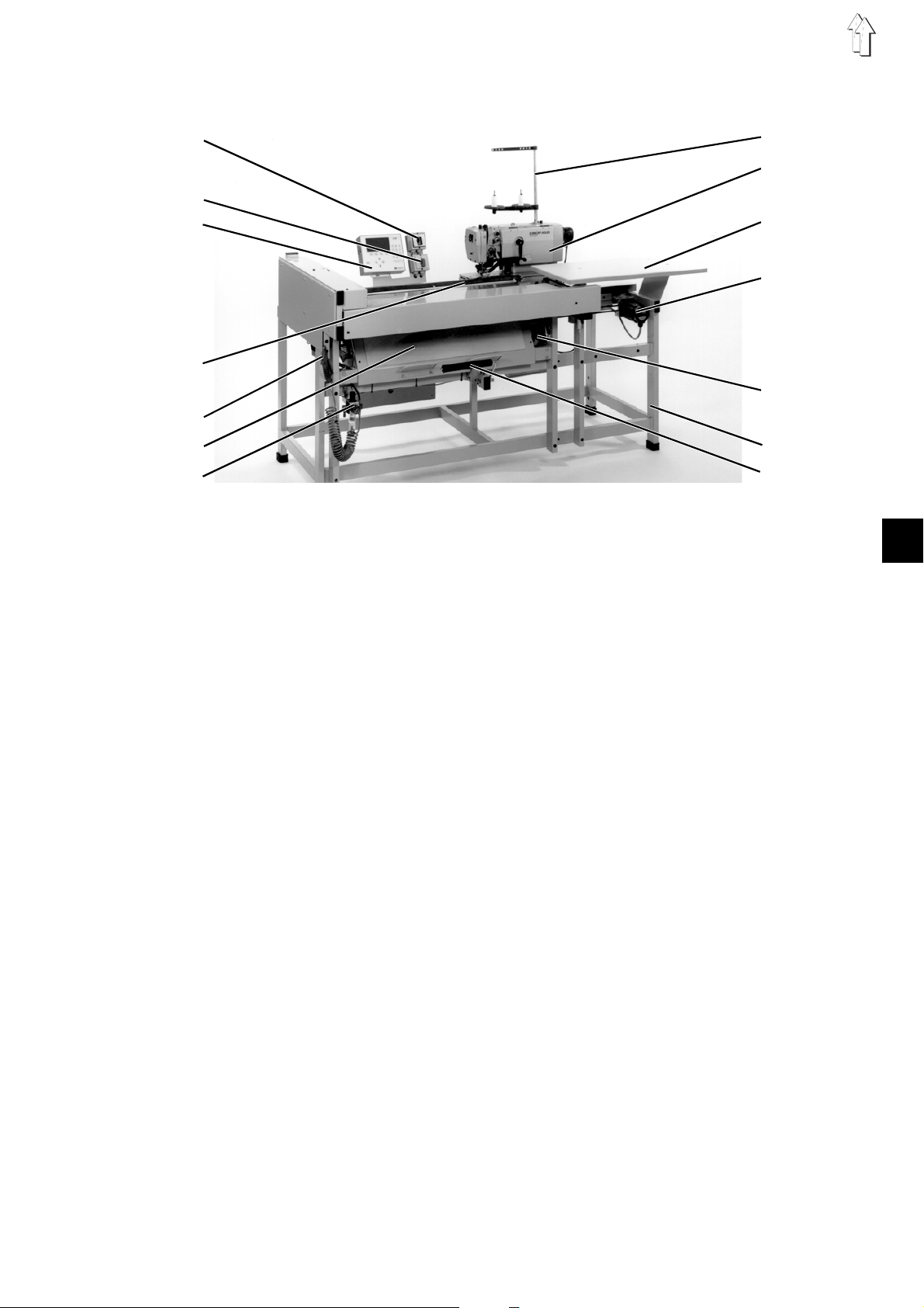
1. Scope of Delivery of the Sewing Unit
1
8
9
2
3
10
11
4
12
5
6
7
The scope of delivery depends on your order.
Please check if all required parts are available before installation.
–
1
Switch for the sewing machine head
–
2
Main switch
–
3
Control panel
–
4
Feed and advancing unit
–
5
Compressed air gun
–
6
Stacker
–
7
Compressed air maintenance unit
–
8
Yarn stand
–
9
Sewing head
–
10
Support table
–
11
Drive for advancing unit
–
12
Sewing drive
–
13
Stand
–
14
Knee switch
–
–
Optional equipment
Small parts in the accessories pack
13
14
2
3
Page 3
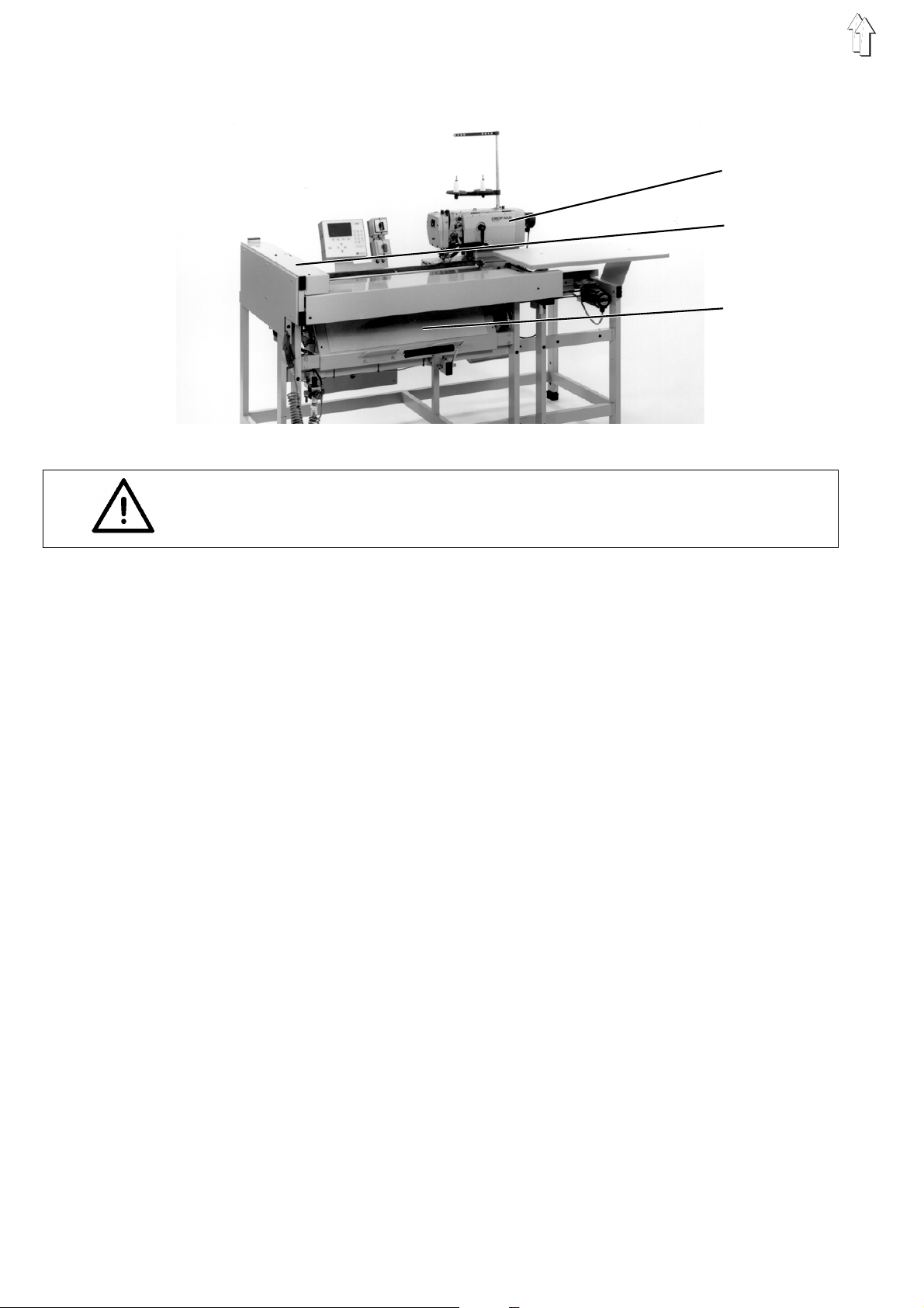
2. Installing the Sewing Unit
ATTENTION !
The sewing unit may only be installed by trained personnel.
1
2
3
2.1 Transport Guards
The transport guards are found at the following places:
–
Sewing head 1
–
Feed and advancing unit 2
–
Stacker 3
Removing the transport guards
–
Remove the securing bands and wooden laths on the machine
head, machine table and on the stand.
4
Page 4
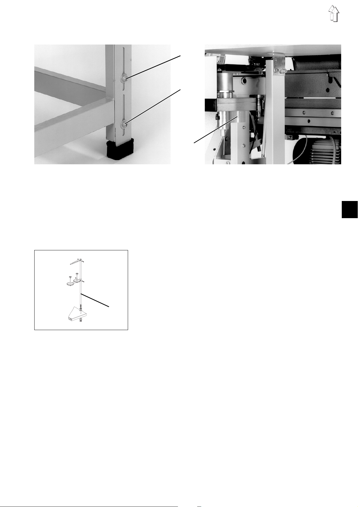
2.2 Aligning the Sewing Unit
1
2
3
The sewing unit can be aligned using the table leg. Care must be
taken to see that the table lies horizontal.
–
Place a water level on the stand.
–
Loosen screws 1 and 2.
–
Align the table top horizontal
–
Tighten screws 1 and 2.
2
2.3 Attaching the Yarn Stand
4
2.4 Connecting the Vacuum
–
Insert the yarn stand 4 into the drilled hole of the yarn stand holder 3.
–
Fasten the yarnstand with nuts and washers.
–
Mount and align the yarn spool holder and take-off arm as shown
in the illustration.
The vacuum of the feeding device fixes the aligned sewing material.
The feeding device is prepared for connection to an in-house vacuum
facility.
If no in-house vacuum facility exists, then the rotary blower and the
vacuum distributor available as optional equipment must be ordered.
–
Connect the suction hose of an in-house vacuum facility or a
vacuum distributor to the suction connexion 3.
5
Page 5

2.5 Checking the V-belt Tension
Caution Risk of Injury !
Check the V-belt tension only with the sewing unit turned off.
1
2
3
Checking the V-belt Tension
–
It must be possible to press in the V-belt 1 of the sewing drive
approx. 10 mm in the middle with a finger.
Correcting the V-belt tension
–
Loosen the nuts 2.
–
Adjust the V-belt tension by swinging the sewing drive 3.
–
Tighten the nuts 2.
6
Page 6

3. Electrical Connection
3.1 Mounting the Control Panel
1
ATTENTION !
All work on the electrical equipment of the sewing unit may only be
performed by electricians or appropriately instructed persons.
The mains plug must be pulled out.
It is essential that the enclosed operating instructions of the sewing
drive and the servo-motor manufacturers be observed!
2
3
4
5
–
Push control panel 2 with the two clamping pieces 3 onto bar 4.
–
Set the angle of the control panel.
–
Tighten the screws on the two clamps 3.
–
Loosen the clamping screw 5.
–
Turn the control panel so that the operator has an optimum view of
the display.
–
Tighten the clamping screw 5.
–
Carefully insert the connection plug 1 into the socket in the back of
the control panel.
–
Tighten the screws of the connection plug.
2
7
Page 7

3.2 Checking the Nominal Voltage
3 - 2: 190 V
3 - 1: 200 V
4 - 2: 210 V
4 - 1: 220 V
5 - 2: 230 V
5 - 1: 240 V
5 4 3 2 1
230 V
ATTENTION !
The nominal voltage listed on the ratings plate of the sewing drive and
the mains voltage must correspond!
An adaption to the local mains voltage occurs via the terminals 1 to 5
on the transformer 1 of the sewing drive.
At delivery, the sewing drive is set to a mains voltage of 230 V
(terminals 5 and 2).
–
Check the arrangement of the connections on the transformer of
the sewing drive.
–
Change the connections to correspond to the existing mains
voltage, if necessary.
The direct currect sewing drives used are operated with a "single
phase-alternating-voltage".
In order to avoid overloading a single phase of a threephase mains
supply when connecting multiple sewing units, the following is to be
observed:
–
The connections of the individual sewing units must be distributed
equally to the phases of the threephase mains supply.
–
The wiring for connection to a threephase mains supply is shown
in the construction circuit diagram.
8
Page 8

4. Pneumatic Connection
1
4.1 Connecting the Compressed Air Maintenance Unit
For operation of the pneumatic components, the sewing unit must be
supplied with water-free compressed air.
ATTENTION !
For a flawless functioning of the pneumatic control procedures the
compressed air supply must operate as follows:
The compressed air supply must be so that even at the moment of
greatest air consumption the minimum operating pressure may not
drop below
The pneumatic system of the sewing unit must be supplied with
water-free compressed air.
The line overpressure must be between 8 to 10 bar.
–
Connect the compressed air maintenance unit to the in-house
compressed air supply with connection hose 1 ( Ø = 9 mm) and the
hose coupling G1/4.
5 bar
.
2
Pneumatic connections package
A pneumatic connections package for stands with compressed air
maintenance unit and pneumatic optional equipment is available under
order no. 0797 003031.
The connections package contains the following components:
–
Connection hose, 5m long, Ø = 9 mm
–
Hose nozzles and hose clamps
–
Coupling socket and coupling plug
9
Page 9

4.2 Setting the Operating Pressure
1
2
The operating pressure of the sewing unit is
It can be seen at manometer 2.
–
To set the operating pressure pull up knob 1 and turn.
Turn clockwise = Increase pressure
Turn counterclockwise = Reduce pressure
6 bar
.
10
Page 10

5. Refilling the oil
Caution Risk of Injury !
Oil can cause skin rashes.
Avoid longer skin contact.
After contact wash yourself thoroughly.
ATTENTION !
The handling and disposal of mineral oils is subject to legal constraints.
Deliver used oil to an authorized reception point.
Protect your environment.
Take care nicht to spill any oil.
5.1 Filling the oil reservoir
For filling the oil reservoir use only
an equivalent oil with following specification:
–
Viscosity at 40 °C: 10 mm
–
Flashpoint: 150 °C
ESSO SP-NK 10
offices under the following parts no.s:
–
2 liter container: 9047 000013
–
5 liter container: 9047 000014
Hook lubrication
is available from
ESSO SP-NK 10
2
/s
DÜRKOPP -ADLER AG
lubricating oil or
sales
2
1
Caution Risk of Injury !
Fill oil only with the sewing unit turned off.
–
Turn off the sewing unit.
–
Swing the advancing unit to the side so that the machine head can
be tilted up.
–
Tilt the machine head up.
–
Fill reservoir 1 through the filling opening up to the "
–
Tilt the machine head down.
max
" mark.
11
Page 11

Lubrication of the machine head
2
–
Fill reservoir 2 through the filling opening up to the "
5.2 Lubricating Wicks and Felts
Before the initial operation and after a longer period of standstill the
Wicks and felts should be soaked in oil.
5.3 Regulating of the Hook Lubrication
WARNING !
To ensure sufficient lubrication during the running-in period, a
relatively high amount of oil supply is pre-set by the factory.
This setting is to be checked and corrected after the running-in period.
3
max
" mark.
12
–
The amount of the oil supply is adjustable with screw 3.
Page 12

6. Commissioning
<==== REF
A sewing trial is to be conducted after completion of the installation work!
–
Insert the mains plug.
Caution Risk of Injury !
Turn off the main switch.
Thread the needle thread and underthread only with the sewing unit
turned off.
–
Thread the needle thread (see Operating Instructions).
–
Insert a full underthread bobbin (see Operating Instructions).
Caution Risk of Injury !
During the reference run do nicht reach into the motion area of the
feed rail.
–
Turn on the main switch.
The controls load the machine program.
The DÜRKOPP-ADLER logo appears briefly in the display of the
control panel.
–
The operator is prompted to start the reference run by the
<==== REF
"
–
Operate the start key.
The feed rail runs slowly into its left end position.
–
The screen changes to the main display.
–
Feed the material to be worked.
–
Switch on the vacuum by operating the knee switch.
–
Start the sewing sequence by operating the start key.
–
Check if the buttonholes meet the desired requirements.
If the requirements are not met, change the thread tensions (see
Operating Instructions).
" message.
2
13
 Loading...