


Manual, complete
745 - 34 - 2
Sewing unit for runstitching of piped flap
and welt pocket openings and pocket corners
Working methods: A, B, D, F
Operating Instructions
Installation Instructions
Service Instructions
Instructions for Programming DAC
1
2
3
4
Postfach 17 03 51, D-33703 Bielefeld • Potsdamer Straße 190, D-33719 Bielefeld
Telefon + 49 (0) 5 21 / 9 25-00 • Telefax + 49 (0) 5 21 / 9 25 24 35 • www.duerkopp-adler.com
Ausgabe / Edition: Änderungsindex Teile-Nr./Part.-No.:
08/2007 Rev. index: 01.0 Printed in Federal Republic of Germany 0791 745181

745 - 34 - 2
Manual, complete
Contents
Operating Instructions
Installation Instructions
Service Instructions
Instructions for Programming DAC
Interconnection-diagram
9870 745154 B
9890 745002 B
Pneumatic circuit plan
9770 745005
All rights reserved.
Property of Dürkopp Adler AG and copyrighted. Reproduction or publication of the content in
any manner, even in extracts, without prior written permission of Dürkopp Adler AG, is
prohibited.
Copyright ©
Dürkopp Adler AG - 2007

Foreword
This instruction manual is intended to help the user to become familiar
with the machine and take advantage of its application possibilities in
accordance with the recommendations.
The instruction manual contains important information on how to
operate the machine securely, properly and economically. Observation
of the instructions eliminates danger, reduces costs for repair and
down-times, and increases the reliability and life of the machine.
The instruction manual is intended to complement existing national
accident prevention and environment protection regulations.
The instruction manual must always be available at the machine/sewing
unit.
The instruction manual must be read and applied by any person that is
authorized to work on the machine/sewing unit. This means:
– Operation, including equipping, troubleshooting during the work
cycle, removing of fabric waste,
– Service (maintenance, inspection, repair) and/or
– Transport.
The user also has to assure that only authorized personnel work on the
machine.
The user is obliged to check the machine at least once per shift for
apparent damages and to immediatly report any changes (including the
performance in service), which impair the safety.
The user company must ensure that the machine is only operated in
perfect working order.
Never remove or disable any safety devices.
If safety devices need to be removed for equipping, repairing or
maintaining, the safety devices must be remounted directly after
completion of the maintenance and repair work.
Unauthorized modification of the machine rules out liability of the
manufacturer for damage resulting from this.
Observe all safety and danger recommendations on the machine/unit!
The yellow-and-black striped surfaces designate permanend danger
areas, eg danger of squashing, cutting, shearing or collision.
Besides the recommendations in this instruction manual also observe
the general safety and accident prevention regulations!

General safety instructions
The non-observance of the following safety instructions can cause
bodily injuries or damages to the machine.
1. The machine must only be commissioned in full knowledge of the
2. Before putting into service also read the safety rules and
3. The machine must be used only for the purpose intended. Use of
4. When gauge parts are exchanged (e.g. needle, presser foot, needle
5. Daily servicing work must be carried out only by appropriately
instruction book and operated by persons with appropriate training.
instructions of the motor supplier.
the machine without the safety devices is not permitted. Observe all
the relevant safety regulations.
plate, feed dog and bobbin) when threading, when the workplace is
left, and during service work, the machine must be disconnected
from the mains by switching off the master switch or disconnecting
the mains plug.
trained persons.
6. Repairs, conversion and special maintenance work must only be
carried out by technicians or persons with appropriate training.
7. For service or repair work on pneumatic systems, disconnect the
machine from the compressed air supply system (max. 7-10 bar).
Before disconnecting, reduce the pressure of the maintenance unit.
Exceptions to this are only adjustments and functions checks made
by appropriately trained technicians.
8. Work on the electrical equipment must be carried out only by
electricians or appropriately trained persons.
9. Work on parts and systems under electric current is not permitted,
except as specified in regulations DIN VDE 0105.
10. Conversion or changes to the machine must be authorized by us
and made only in adherence to all safety regulations.
11. For repairs, only replacement parts approved by us must be used.
12. Commissioning of the sewing head is prohibited until such time as
the entire sewing unit is found to comply with EC directives.
13. The line cord should be equipped with a country-specific mains
plug. This work must be carried out by appropriately trained
technicians (see paragraph 8).
It is absolutely necessary to respect the safety
instructions marked by these signs.
Danger of bodily injuries !
Please note also the general safety instructions.

Index Page:
Part 2: Installation Instructions 745-34-2
1. Scope of delivery .............................................. 3
2. General notes ................................................ 3
3. Installing the sew ing unit
3.1 Transport.................................................... 4
3.2 Removingthesecuritydevices....................................... 5
3.3 Settingtheworkingheight ......................................... 6
3.4 Adjusting the foot pedals .......................................... 7
4. Attaching the machine parts removed for shipping
4.1 Threadreelholder.............................................. 8
4.2 Cylinder for pick-up folder stroke ..................................... 9
4.3 Workpieceboxes............................................... 10
4.4 Fastening the holder for control panel, bobbin winder and right-hand tray............. 11
4.5 Table extension (optional equipment)................................... 12
4.5.1 Table extension for working method with bundle clamp carriage ................... 12
4.5.2 Tableextensionforstackingtotheside ................................. 13
4.6 Throw-over stacker (optional equipment) ................................ 14
2
5. Electrical connection
5.1 Connecting the control panel DAC III ................................... 16
5.2 Connecting the external bobbin winder.................................. 16
5.3 Checking the nominal voltage and connecting to the mains ..................... 17
5.4 Checking the nominal voltage of the vacuum device (optional equipment) ............ 20
5.5 Directionofrotationofthesewingmotorandthevacuumblower ................. 20
6. Pneumatic connection ........................................... 21
7. Connection to the factory-own vacuum unit ............................. 22
8. Oil lubrication ................................................ 23
9. Commissioning ............................................... 24
10. Installing the sew ing software
10.1 General ..................................................... 24
10.2 Loading the program............................................. 25
10.3 Dongle-Update via the Internet ...................................... 26

1. Scope of delivery
–
Basic sewing unit for runstitching of piped, flap and welt pocket
openings with rectangular and slanted pocket corners, consisting
of:
–
Height-adjustable stand
–
Step motors for sewing drive, material feed, length adjustment
of the corner incision device
–
Twin needle lockstitch machine
–
DAC III control with control panel
–
Laser marking lamps
–
Sewing light
–
Compressed air maintenance unit with compressed air pistol
–
Thread reel holder
–
Workpiece boxes for additional parts to the left of the operator
and underneath the table top
–
Tools and small parts in the accessories
–
Feeding and sewing equipment according to the working
method
–
Optional equipment
2. General notes
2
ATTENTION !
The sewing unit must only be assembled by trained specialist staff.
Any work on the electrical equipment of the sewing unit must
only be c arried out by electricians or correspondingly instructed
persons.
The mains plug must be pulled out.
The enclosed operating instructions of the s tep motor manufacturer
have to be observed in any case.
3
3. Installing the sewing unit
3.1 Transport
For in-house transport the stand is equipped with four castors.
ATTENTION !
Do not lift the sewing unit at the table tops.
Use an elevating platform truck or a forklift truck.
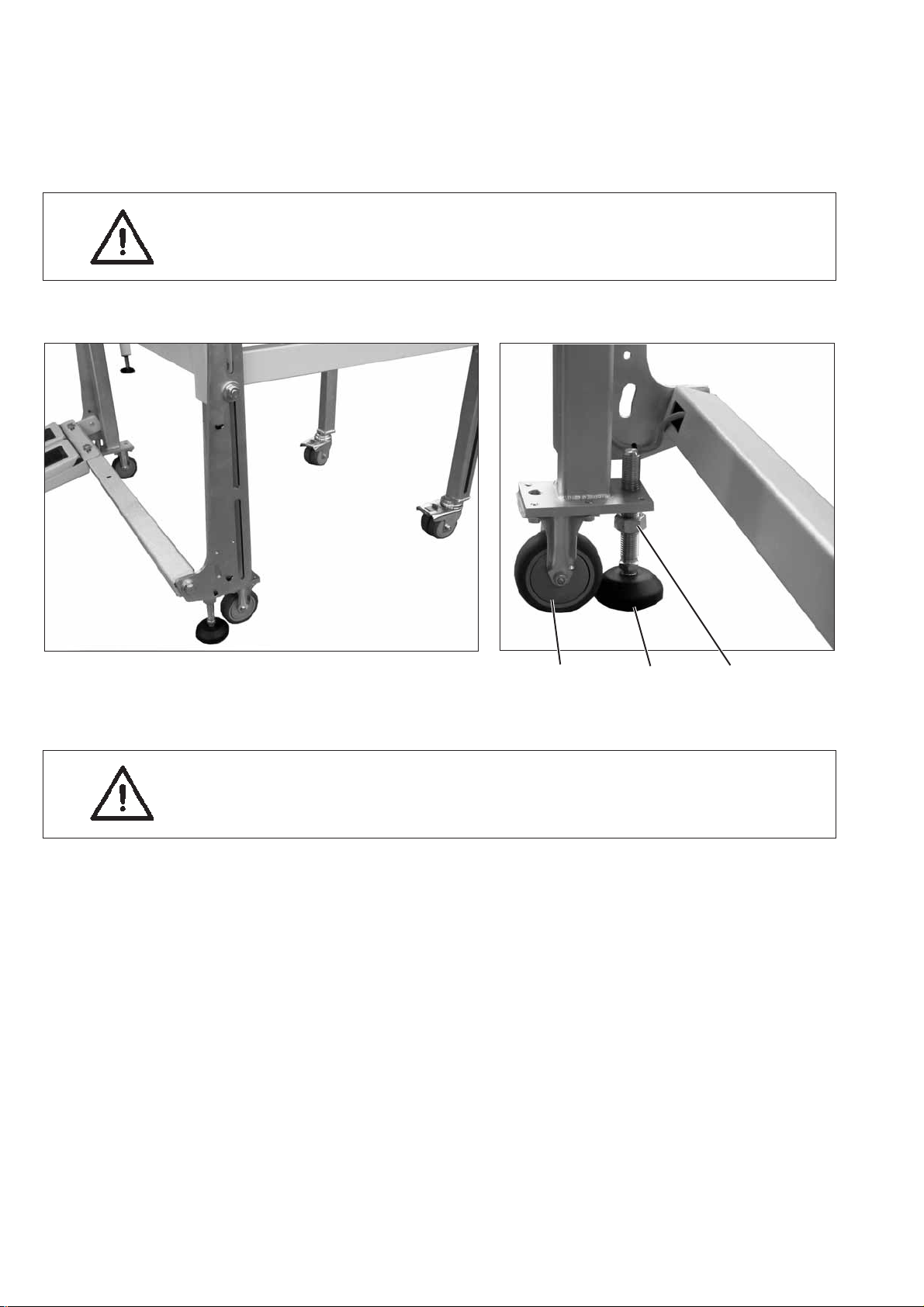
321
ATTENTION!
Before commissioning the sewing unit screw out the s tand
feet 2 and 3 until a s ecure footing is achieved.
Lifting the sew ing unit
–
Push the elevating platform truck or the forklift forks into the
openings 1 at the back of the sewing unit.
Rolling the sewing unit
–
For transport purpose unfasten the stand feet 2 and 3 by turning
them to the right.
–
After transport secure the sewing unit by turning the stand feet 2
and3totheleft.
4
3.2 Removing the securing devices
Before installing the sewing unit all six securing devices have to be
removed.
If the sewing unit has to be transported to another place, please use
the securing devices again.
2
5

3.3 Setting the working height
12
The working height can be set between 79 cm and 110 cm
(measured up to the upper edge of the table top).
The sewing unit is set to the lowest working height of 79 cm by the
manufacturer.
ATTENTION: Danger of breakage !
When loosening the securing screws.
The sewing unit may overturn when the tubular feet of the frame are
pulled out.
Set the height of the sewing unit by pulling equally the tubular feet of
the frame.
–
Loosen the nut 1 ( 4x) and the s houlder bolts 2 (4x) (clamping of the
front tubular foot).
–
Loosen screws 3 (4x) (clamping of the rear tubular foot).
–
Set the table top to the desired height to be flush.
–
To avoid a tilting, pull out / push in the tubular feet uniformly on
both side.
–
Tighten the shoulder bolts 2 and the screws 3.
–
If you want to set the foot pedal afterwards, please do not tighten
the nut 1 yet. Otherwise it can also be tightened.
3
6

3.4 Adjusting the foot pedals
1 243
43 5
The height of the foot pedals can also be set, independently of the
height of the sewing unit.
The angle of slope and the lateral position of the foot pedals are also
adjustable.
Setting the height
–
Loosen nut 1 and shift both guides 2 in the slotted hole.
Loosen the screws 3 additionally, in order to displace them in the
next slotted hole.
Make sure to have the same height in both guides 2.
–
Tighten the nut 1.
Setting the angle of slope
–
Unscrew the screw 4 and swivel the pedal.
–
Adjust the angle of slope of the pedal.
–
Tighten the screws 3 (2x) and screw 4 with the pedal at the desired
position.
Setting the lateral position
–
Loosen the screws 5 and shift the pedal laterally.
–
Tighten screws 5 again.
2
7

4. Attaching the machine parts removed for shipping
4.1 Thread reel holder
321
–
Insert the thread reel holder 2 in the drill-hole of the table top
and fasten it with nut 4 underneath the table top.
–
Mount and align the reel plate 1 and the unwinding arms 3 as
shown in the illustration.
4
8

4.2 Cylinder for pick-up folder stroke (745-34-2 B/F)
32 1
–
Remove the securing device and swivel the cylinder upwards.
–
Fasten the cylinder fixture 1 to plate 3 with screws 4.
–
Move the fixture for the pick-up folder by hand.
The movement must be fingertip easy over the whole cylinder
stroke.
Correction
–
Loosen screws 3 a little and move the fixture for the pick-up folder
over the whole cylinder stroke.
In the course of this the cylinder fixture aligns itself.
–
Tighten screws 3.
–
Check the free movement once again.
2
9

4.3 Workpiece boxes
43 21
–
Fasten the workpiece boxes onto rod 2.
For this purpose push the clamping pieces 4 and 3 on rod 2, align
the height and clamp them firmly by tightening the screws.
–
Loosen the screw at clamping lever 1 and align the workpiece
boxes to the sewing station.
–
Tighten the screw at clamping lever 1.
10

4.4 Fastening the holder for control panel, bobbin winder and right-hand tray
6 543 21
Control panel
–
Fasten angle 6 and control panel 5 to bolt 3 with nut 4.
–
Fasten cable 1 to bolt 3 with screw 2.
Bobbin winder and tray
–
Push holder 11 with angle 10 onto the table top and tighten
with the screw.
–
Align the arms 9 and 12.
–
Fasten the tray 8 to the lower arm.
–
Fasten the bobbin winder 7 to the upper arm.
See chapter 5.2 for connecting the bobbin winder.
7 1210119 8
2
11

4.5 Table extensions (optional equipment)
4.5.1 Tableextension for working method with bundle clamp carriage (Order No. 0745 597674)
321
–
Fasten the table extension 3 onto the table top brace with the
screws 2.
–
Loosen screws 1 slightly.
Create a clearance to the table top by shifting the table extension 3.
This clearance is required for the free passage of the positioned
pocket bag.
12

4.5.2 Tableextension for stacking to the side (Order No. 0745 597684)
53
–
Fasten table extension 2 to the front of the rest table brace with the
screws 1.
–
Screw angle 3 on table top 4 with two screws.
21
2
45
13

4.6 Throw-over stacker (optional equipment)
325 4 1
78
46
10 9
14
The throw-over s tacker 1 (Order No. 0745 597554) is fastened to the
stand of the sewing unit with mounting pipe 2.
–
Fasten the mounting pipe 2 in the right stacking opening 4 with
screws, washers and shackle 3.
–
Push the throw-over stacker towards the stand of the sewing unit.
–
Fasten spars 5 and 6 on spar 2 with the shackle and the two
brackets 7.
–
Insert the c oupling plug of the compressed air supply (thick hose)
into hose coupling 8.
–
Insert the coupling plug of the control conduit (thin hose) into
coupling 9.

Aligning the stacker
15 14
–
Shift the stacker laterally in such a way that spar 11 is flush with
the table top edge 13.
–
Loosen the clamping lever 14.
–
Move the stacker up on cylinder 15 so that the moving smoother 12
does not hit the table top.
–
Tighten the clamping lever 14.
12 11 13
2
15

5. Electrical connection
ATTENTION!
Any work on the electrical equipment of the sewing unit must
only be c arried out by electricians or correspondingly instructed
persons.
The mains plug must be pulled out.
5.1 Connecting the control panel DACIII
21
–
Carefully insert plug 1 into the rear panel of the control panel.
–
Tighten the screws 2 of plug 1.
5.2 Connecting the external bobbin winder
–
Insert the plug of the bobbin winder into the socket 3 underneath
the table top and secure with a cap nut.
–
Connect the potential compensation cable 4.
4
3
16

5.3 Checking the nominal voltage and connecting to the mains
The adaptation to the local mains voltage has to be done. The switch
element 2 of the main switch 1 has to be corrected accordingly.
–
Remove the mains plug.
–
Loosen the screw in the switch handle and remove the cover
(steps 2-5).
–
Check the configuration of the connections at the switch
element and change the c onnections accordingly
(see interconnection-diagram, s heet 1, e.g. next figure).
–
Attach the cover again and fasten the screw.
–
21
Connect the mains plug.
2
17

Legend: bl=blue / sw=black / bn=brown / gn-ge= green, yellow
18

Legend: bl=blue / sw=black / bn=brown / gn-ge= green, yellow
2
19

5.4 Checking the nominal voltage of the vacuum device (optional equipment)
1
The adaptation to the local mains voltage has to be done at the
terminal strip in control box 1.
–
Screw off the cover of control box 1.
–
Check the arrangement of the connections to the terminal strip.
(see circuit diagram).
–
If necessary, change the connections according to the local mains
voltage.
–
Put the cover on the control box 1 again and screw on.
Legend: bl=blue / sw=black / bn=brown / gn-ge= green, yellow
5.5 Direction of rotation of the sewing motor and the vacuum blower
•
The sewing unit is equipped with the latest s tep motor technology.
A check of the direction of rotation of the sewing motors is not
required because it is automatically set by the control.
•
The direction of rotation of the vacuum blower can be inverted by
exchanging the phase (plug).
20

6. Pneumatic connection
For the operation of the pneumatic components the sewing unit has to
be supplied with anhydrous compressed air.
ATTENTION !
For a trouble-free function of the pneumatic control procedures the
compressed air supply must operate as follows:
Even at the moment of the highest air consumption the minimum
operating pressure must not drop below 6bar.
In case of a too high loss of pressure:
–
–
3
Increase the compressor output.
Increase the diameter of the compressed air hose.
4
2
1
2
Connecting the maintenance unit for compressed air
–
Connect the connection hose 1 (Order No. 0797 003031)tothe
cut-off cock 2 and the compressed air line by means of a hose
coupling ¼ “.
Adjusting the operating pressure
–
The operating pressure amounts to 6 bar.
It can be read off at the manometer 4.
–
For adjusting the operating pressure lift the twist handle 3 and
turn it.
–
Turning in clockwise direction = the pressure is increased
–
Turning counter-clockwise = the pressure is reduced
ATTENTION !
No oil-bearing compressed air must be fed from the compressed
air line.
Behind the filter cleaned compressed air is withdrawn as blowing air
for cleaning machine parts and for blowing workpieces out.
Oil particles contained in the blowing air lead to malfunctions and
stains on the workpieces.
21

7. Connection to the factory-own vacuum unit
1
The suction unit facilitates the precise feeding and positioning of the
workpiece on the work table 1.
–
Connect the hose of the factory-own vacuum unit to the connection
valve 3.
Note:
In case no factory-own vacuum unit is available, the vacuum device
(Order No. 0745 597964) has to be ordered in addition.
ATTENTION !
When mounting the vacuum device (side-channel blower) it is
absolutely necessary to exchange the joint ring 2 (black) at the
connection valve against a filter ring (white) included in the
accessories.
32
22

8. Oil lubrication
1
Caution: Danger of injury !
Oil can cause skin rashes.
Avoid longer skin contact.
After contact wash yourself thoroughly.
ATTENTION !
The handling and disposal of mineral oils is subject to legal
regulations.
Deliver used oil to an authorized collecting station.
Protect your environment.
Be careful not to spill any oil.
For filling up the oil reservoirs use nothing but DA-10 lubricating oil or
an equivalent oil with the following specification:
–
Viscosity at 40° C: 10 mm
–
Ignition point: 150° C
DA-10 is available from the DÜRKOPP ADLER AG sales offices under
the following parts numbers:
250 ml-Container: 9047 000011
1 l - Container: 9047 000012
2 l - Container: 9047 000013
5 l - Container: 9047 000014
2
/s
32
2
23
Oil reservoir for the lubrication of the machine head
–
Fill oil reservoir 1 with oil through the drill-holes in the inspection
glass.
The oil level must be between the “Min” and “Max” markings.
Oil reservoir for the hook lubrication
–
Tilt the machine head up (see Operating Instructions, chapter 2.3).
–
Fill the oil reservoir 2 with oil up to the “max.” marking through
nipple 3 (see sketch).
23

9. Commissioning
After completion of the installation work a sewing test should be made.
–
Plug in the mains plug.
Caution: Danger of injury !
Switch off the main switch before threading in the needle and hook
thread.
Laser light.
Do not look into the light source.
–
Thread in the needle thread (see Operating Instructions,
chapter 2.5).
–
Thread in the hook thread (see Operating Instructions,
chapter 2.8).
–
Switch on the main switch.
The control is initialized.
–
Step back on the left pedal.
The reference run starts.
The transport carriage moves in its rear end position.
The reference run is necessary in order to get a defined initial
position of the transport carriage.
–
By actuating the left pedal the various steps of the positioning
procedure are triggered sequentially and the sewing cycle is
started.
ATTENTION !
At the sewing start the workpiece must lie under the feeding clamps.
Movement of the transport carriage without material damages the
coating of the feeding clamps.
–
–
10. Installing the software
10.1 General
Loading a specific sewing software in the DACIII control unit is
possible with the help of the “Programmed Dongle”.
The “Programmed Dongle” has a label indicating the class and
software version. Such a loading (booting) may be used in order to
provide several DACIII control unit with a sewing software (first
installation) or to install a newer machine software (update).
For selecting the sewing program and for the further settings of the
control unit s ee Part 4: Programming Instructions 745-34-2.
Positioning and operation are described in Part 1: Operating
Instructions 745-34-2.
24

10.2 Loading the program
With the delivery of the machine only the test software (allowing the
loading of sewing software) is installed in the control unit. The test
software offers no further functions. If the test software gets damaged
during the loading process, it is no longer possible to load a software
using a dongle.
In such a case use a PC with a loader cable.
Hint:
The sewing unit is delivered with a machine software installed on it.
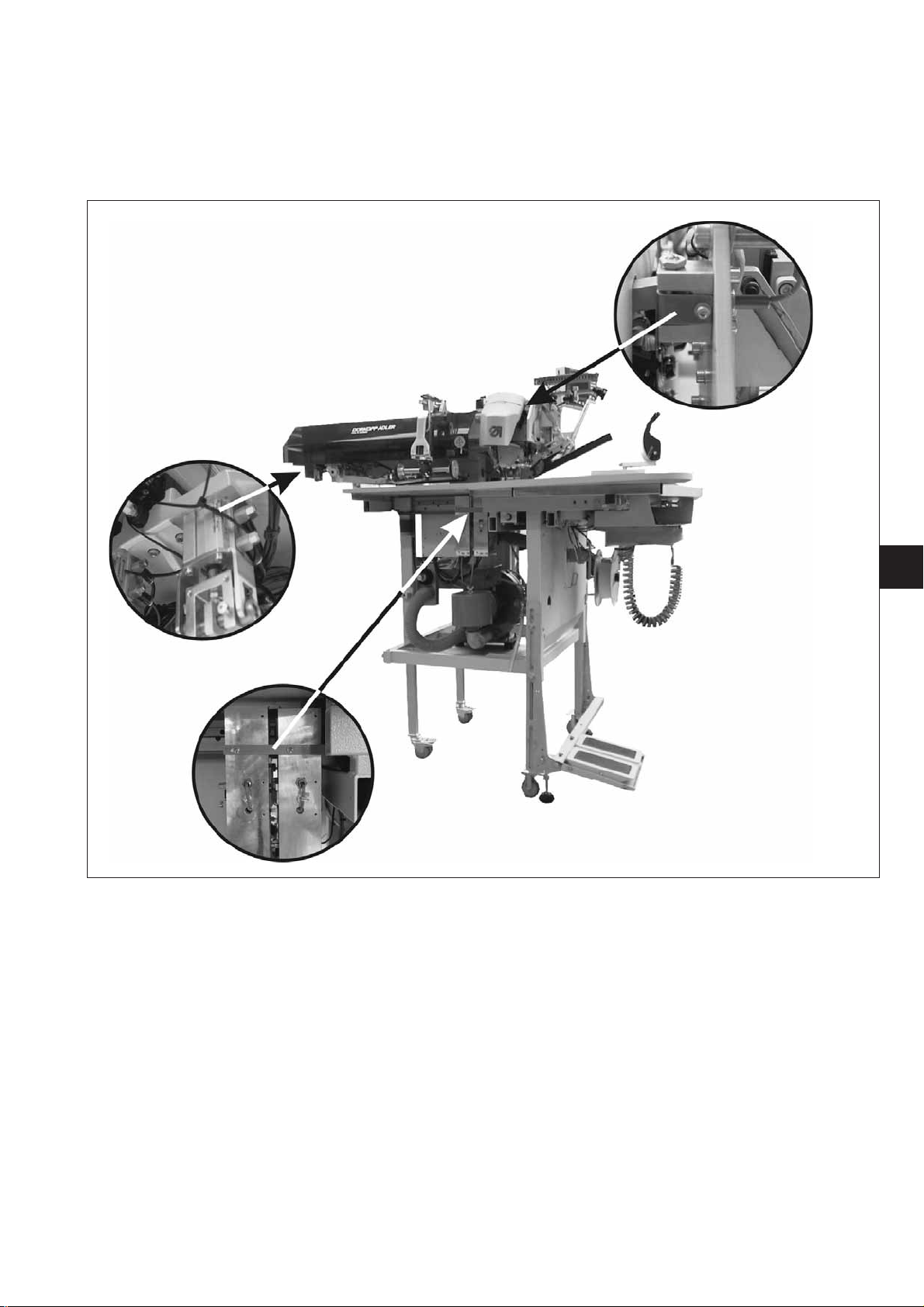
CAUTION !
Turn off the main switch before connecting the dongle.
–
Turn the machine off at the main switch.
–
Insert the dongle 2 into the socket X110 (TEST-Interface) 1 of the
control unit (see pictures).
–
Switch on the main switch. The Software will be loaded. The
loading process takes less than 60 seconds.
–
During the loading process do not remove the dongle and do not
switch off the machine (otherwise you will damage the software) !
–
During this time, the version of the control panel will be displayed ,
e.g. “BF1 C A 03" (blue screen).
–
When the loading process is finished, the program version will be
displayed e.g. “745 A01”.
–
The new operating system must be confirmed via the “OK”key.
Then the operating system will be started.
–
Remove the dongle 2 from the socket X110..
–
Confirm the software version by pressing the “OK” key.
–
The machine is ready for operation.
2
Hint!
Remove the dongle before re-starting the machine, otherwise it will
load the sewing program again.
After a replacement (first installation) of the DAC III control, the error
message Error 9900 or Error 9901 or Error 9902 will be displayed after
loading the operating system.
An initialization must first be carried out (see part 4 chapter 6).
.
1
2
25

10.3 Dongle-Update via Internet
Dongles can be updated with programs available from the Dürkopp
Adler homepage. Please visit our homepage
“www.duerkopp-adler.com” where you will find the relevant programs in
the “Download” - section. Prerequisite is our auxiliary download
software “ Dongle Copy ” which is available in the same section
together with instructions for easy use.
If you want to overwrite the machine software on it, the dongle
will first b e deleted (formatted).
The programs (sequences, parameters) saved in the dongle will then
be deleted. If still needed, please make a backup of the files into a
computer (desktop, notebook).
The required software “Dongle Copy” is available in the “Download
Area” of our web site.
26
 Loading...