

Page 1
609
Spezialnähmaschine
Betriebsanleitung
Instruction manual
D
GB
Postfach 17 03 51, D-33703 Bielefeld • Potsdamer Straße 190, D-33719 Bielefeld
Telefon +49 (0) 521 / 9 25-00 • Telefax +49 (0) 521 / 9 25 24 35 • www.duerkopp-adler.com
Ausgabe / Edition: Änderungsindex Teile-Nr./Part.-No.:
10/2007 Rev. index: 01.0 Printed in Federal Republic of Germany 0791 609741
Page 2

Alle Rechte vorbehalten.
Eigentum der Dürkopp Adler AG und urheberrechtlich geschützt. Jede, auch auszugsweise
Wiederverwendung dieser Inhalte ist ohne vorheriges schriftliches Einverständnis der Dürkopp Adler AG
verboten.
All rights reserved.
Property of Dürkopp Adler AG and copyrighted. Reproduction or publication of the content in any manner,
even in extracts, without prior written permission of Dürkopp Adler AG, is prohibited.
Copyright ©
Dürkopp Adler AG - 2007
Page 3

Foreword
This instruction manual is intended to help the user to become familiar
with the machine and take advantage of its application possibilities in
accordance with the recommendations.
The instruction manual contains important information on how to
operate the machine securely, properly and economically. Observation
of the instructions eliminates danger, reduces costs for repair and
down-times, and increases the reliability and life of the machine.
The instruction manual is intended to complement existing national
accident prevention and environment protection regulations.
The instruction manual must always be available at the machine/sewing
unit.
The instruction manual must be read and applied by any person that is
authorized to work on the machine/sewing unit. This means:
– Operation, including equipping, troubleshooting during the work
cycle, removing of fabric waste,
– Service (maintenance, inspection, repair) and/or
– Transport.
The user also has to assure that only authorized personnel work on the
machine.
The user is obliged to check the machine at least once per shift for
apparent damages and to immediatly report any changes (including the
performance in service), which impair the safety.
The user company must ensure that the machine is only operated in
perfect working order.
Never remove or disable any safety devices.
If safety devices need to be removed for equipping, repairing or
maintaining, the safety devices must be remounted directly after
completion of the maintenance and repair work.
Unauthorized modification of the machine rules out liability of the
manufacturer for damage resulting from this.
Observe all safety and danger recommendations on the machine/unit!
The yellow-and-black striped surfaces designate permanend danger
areas, eg danger of squashing, cutting, shearing or collision.
Besides the recommendations in this instruction manual also observe
the general safety and accident prevention regulations!
Page 4

General safety instructions
The non-observance of the following safety instructions can cause
bodily injuries or damages to the machine.
1. The machine must only be commissioned in full knowledge of the
2. Before putting into service also read the safety rules and
3. The machine must be used only for the purpose intended. Use of
4. When gauge parts are exchanged (e.g. needle, presser foot, needle
5. Daily servicing work must be carried out only by appropriately
instruction book and operated by persons with appropriate training.
instructions of the motor supplier.
the machine without the safety devices is not permitted. Observe all
the relevant safety regulations.
plate, feed dog and bobbin) when threading, when the workplace is
left, and during service work, the machine must be disconnected
from the mains by switching off the master switch or disconnecting
the mains plug.
trained persons.
6. Repairs, conversion and special maintenance work must only be
carried out by technicians or persons with appropriate training.
7. For service or repair work on pneumatic systems, disconnect the
machine from the compressed air supply system (max. 7-10 bar).
Before disconnecting, reduce the pressure of the maintenance unit.
Exceptions to this are only adjustments and functions checks made
by appropriately trained technicians.
8. Work on the electrical equipment must be carried out only by
electricians or appropriately trained persons.
9. Work on parts and systems under electric current is not permitted,
except as specified in regulations DIN VDE 0105.
10. Conversion or changes to the machine must be authorized by us
and made only in adherence to all safety regulations.
11. For repairs, only replacement parts approved by us must be used.
12. Commissioning of the sewing head is prohibited until such time as
the entire sewing unit is found to comply with EC directives.
13. The line cord should be equipped with a country-specific mains
plug. This work must be carried out by appropriately trained
technicians (see paragraph 8).
It is absolutely necessary to respect the safety
instructions marked by these signs.
Danger of bodily injuries !
Please note also the general safety instructions.
Page 5

Content Page:
Part 2: Installation Instructions Class 609
1. Scope of delivery .............................................. 3
2. General and transport packing ..................................... 3
3. Assembling the stand
3.1 Assembling the stand components (MG55-3 stand) .......................... 4
3.2 Assembling the table plate and mounting the control unit ...................... 5
3.3 Settingtheworkingheight ......................................... 7
4. Mounting the machine head
4.1 Fitting the machine head on the table plate ............................... 8
4.2 Earthing .................................................... 9
5. Mounting the table and pedal extension (optional equipment)
5.1 Mounting the table extension ........................................ 10
5.2 Mounting the pedal extension ....................................... 11
6. Sewing drive
6.1 Connecting the HoHsing HVP 70-4-ED-2-CE sewing drive ..................... 12
6.1.1 Connecting the control unit ........................................ 12
6.1.2 Mounting and connecting the external operating panel C300 .................... 13
6.1.3 Mounting and connecting the proximity switch ............................. 13
6.1.4 Connecting the control connection of the thread trimmer and thread tension release ...... 14
7. Checking the mains voltage and connecting the machine .................... 15
8. Setting the sewing drive
8.1 SettingtheHoHsingHVP70-4-ED-2-CEsewingdrive......................... 15
8.1.1 Settingparametersofthecontrolunit .................................. 15
8.1.2 Settingtheproximityswitchandcheckingitspositioning....................... 15
9. Lubrication .................................................. 17
GB
10. Sewing test .................................................. 18
Page 6
1
2
8
3
4
7
6
9
5
Page 7
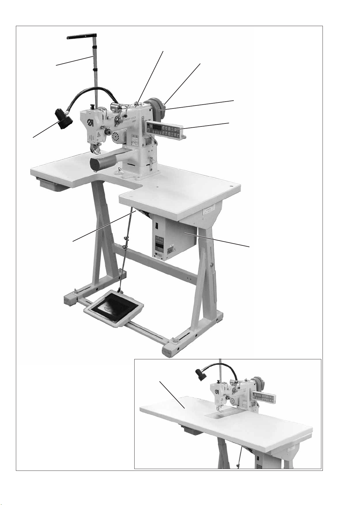
1. Scope of delivery
What items are supplied depends on your order.
Prior to assembling, please check that all the required parts are
present.
This instruction applies to a special sewing machine of which all
individual components are delivered by the Dürkopp Adler AG.
Basic equipment:
–
Machine head with integrated direct drive 1
–
Control unit 5
–
Set value initiator 6
–
External operating panel 4
–
Proximity switch 2
–
Belt guard 3
–
Yarn stand 8
–
Small parts in the accessories
Optional equipment
–
Stand MG55-3 with table plate, pedal with pedal linkage, drawer
–
Table extension 9 (incl. pedal extension)
–
Sewing light with table fastening 7
GB
2. General and transport packing
ATTENTION!
This special sewing machine may only be set up by qualified
personnel.
Transport packing
If you have purchased an assembled special sewing machine, the
following transport protections have to be removed:
–
Safety bands and wooden battens on the machine head, table and
stand.
3
Page 8

3. Assembling the stand
3.1 Assembling the stand components (MG55-3 stand)
3
2
1
–
Assemble the components as shown in the illustration above.
–
Turn the set screw 2 to ensure the stand’s stability.
Each of the stand’s four feet must touch the ground!
–
Screw the oil can holder 3 onto the stand’s left bar.
–
Fix the pedal 1 onto the cross brace.
4
Page 9

3.2 Assembling the table plate and mounting the control unit
The positions of the components that are to mounted are indicated in
the following sketch.
Mains socket (optional
add-on kit)
Cable channel
Punch-mark for the stand
Control
Punch-mark for
set value initiator
Drawer
GB
The measures in brackets are auxiliary sizes defined by the
components.
5
Page 10

5
7
6
1
4
3
2
–
Screw on the drawer 4 with the sockets underneath the left half of
thetableplate.
–
Fix the control unit 1 with three woodscrews (5x30) underneath the
right half of the table plate .
–
Screw on the holder for the strain relief of the mains cable
underneath the table plate.
–
Screw the set value initiator 7 onto the mounting bracket (4 screws
M5x10).
–
Fix the bracket with the set value initiator underneath the table
plate with 4 woodscrews (5x30).
–
Screw the cable channel 6 under the table plate.
–
Fix the table plate with woodscrews (6,0x30) on the stand. The
position of the table plate is indicated by the dimensions given in
the sketch.
–
Assemble the pedal linkage 2
–
Hinge the pedal linkage onto the pedal and the set value initiator of
thesewingdrive.
–
Adjust the height of the pedal linkage by turning the screw so that
the pedal, when released has an inclination of about 10°.
–
Insert the yarn holder 5 into the hole of the table plate.
–
Hammer the machine head support 3 into the hole on the table
plate.
6
Page 11

3.3 Setting the working height
1
1
–
The working height can be adjusted between 740 and 900 mm
(measure to the upper edge of the table plate).
–
Undo screws 1 on the stand braces.
–
Adjust the table plate horizontally to the desired working height.
In order to prevent tilting, the table plate must be pulled out or
pushed in regularly on both sides.
–
Tighten both screws 1.
GB
7
Page 12

4. Mounting the machine head
4.1 Fitting the machine head on the table plate
321
Fixing the machine head on the table plate
–
Fix the socket 2 of the machine head with the four screws 3
(M6X60), washers and nuts onto the table plate.
Tilting the machine head
–
Undo the winged screw 1.
–
Swivel the hook to the left.
–
The machine head is unbolted.
–
Tilt the machine head to the side and make it rest on the machine
head support.
8
Page 13

4.2 Earthing
1 2
The earthing cable conducts static electricity charges of the machine
head via the sewing drive to the ground.
–
Connect the earthing cable with push-on contact, flat plug, toothed
washer onto the earthing connection 2 of the control.
–
Bring the earthing cable through the hole in the table plate to the
machine head.
–
Attach the cable socket of the earthing cable with the toothed
washer and self-tapping screw on the socket 1 of the machine
head.
To this end the socket comes ex factory with a bore.
GB
9
Page 14

5. Mounting the table and pedal extension (optional equipment)
5.1 Mounting the table extension
Mount the table extension according to the sketch below:
Preassembling the bracket
–
Preassemble the bracket according to the sketch on left.
Preassembling the table extension
–
Turn the table plate upside down and put the insert plate into the
cutout provided for it.
–
Fix the blocks (4x) with screws on the position of the magnets of
the table plate cutout.
–
Adjust the blocks vertically so that the insert plate is always seated
in the table plate cutout but is kept tight enough by the magnets.
–
Fix the supports (4x) with screws on the punch-outs of the table
plate back side.
Attention !
The brackets must rest with the outside edge, not with the bending
radius, against the edge of the recess!
10
Page 15

Fix the table extension on the table plate
–
Screw the clamp levers into the thread insert, in order to leave an
interstice of > 4 mm.
–
Shift the table extension without the insert plate but with the 4 in a
way that the slits of the 2 brackets at the rear get engaged to the
bolts of the clamp lever.
–
that the into the bores of the table plate. Tighten the w inged
screws with washers from underneath the table plate.
–
Put on the insert plate.
–
Shift the table plate in position.
–
Tighten the clamp levers, if necessary adjust the height of the
extension table by screwing/unscrewing the screws of the front
brackets.
5.2 Mounting the pedal extension
Disassemble and preassemble the pedal and its linkage
–
Disassemble the pedal and its linkage from the stand; the original
linkage will no longer be needed.
–
Attach the pedal to the extension bracket (see sketch).
Mounting the pedal extension (see sketch)
–
Fix the extension bracket with the pedal to the stand.
–
Hook the pedal linkage (a longer one) into the pedal and the set
value initiator. Set it to have the proper length.
GB
11
Page 16

6. Sewing drive
6.1 Connecting the HoHsing HVP 70-4-ED-2-CE sewing drive
ATTENTION!
Only qualified electricians or other persons with an adequate training
may work on the electrical equipment of this special sewing machine.
The mains plug must be removed!
The instruction manual of the drive’s manufacturer must
imperatively be respected!
6.1.1 Connecting the control unit
Connector sockets HoHsing HVP 70-4-ED-2-CE
Effectuate all plug connections according to the sketch shown here.
–
Connection of the sewing drive 1
–
Encoder of the sewing drive 2
–
Set value initiator 3
–
Control connection of the thread trimmer and thread tension
release 4
–
Connection of the external operating panel 5
–
Connection of the proximity switch 6
1
2
6
3
5
4
12
Page 17

6.1.2 Mounting and connecting the external operating panel C300
21 1
–
Screw the external operating panel 2 on the mounting bracket 1.
–
Screw the mounting bracket 1 laterally on the machine head.
–
Bring the connection cable downwards through the cutout in the
table plate .
–
Connect the connection cable with the extension cable and plug it
into the corresponding socket of the control unit.
GB
6.1.3 Mounting and connecting the proximity switch
–
Push the proximity switch 3 onto the flange of the hand wheel.
–
The groove in the proximity switch housing must engage over the
twist protection of the belt guard.
–
Tighten both stud bolts on the proximity switch ring.
–
Bring the connection cable downwards through the cutout of the
table plate.
–
Plug the connection cable into the corresponding socket of the
control unit .
3
13
Page 18

6.1.4 Connecting the control connection of the thread trimmer and thread tension release
1
–
Bring the connection cable upwards through the hole of the table
plate underneath the machine head base.
–
Connect the cables according to the attached 609 wiring diagram,
part number 9890 609001 B and connect the cables to both plugs
with two pins 1.
–
Plug the connection cable into the corresponding socket of the
control unit.
14
Page 19

7. Checking the mains voltage and connecting the machine
ATTENTION!
The rated voltage mentioned on the type plate and the actual mains
voltage must be identical.
–
Fix an appropriate power plug on the cable end
–
Effectuate a power supply with 1x230V 50/60Hz
8. Setting the sewing drive
8.1 Setting the HoHsing HVP 70-4-ED-2-CE sewing drive
8.1.1 Setting parameters of the control unit
The control unit is delivered ex factory ready programmed with the 609
valid sewing parameters. Therefore a setting of parameters before the
putting into operation is not required.
In order to control the settings or after a reset the parameters must be
set according to the parameter list part number 9800 370001 PB40 in
the accessories.
The setting of parameters is explained in the instruction manual that
comes with the sewing drive.
8.1.2 Setting the proximity switch and checking its positioning
The proximity switch must be reset after the following works:
–
Mounting of the proximity switch when assembling the special
sewing machine
–
Unscrewing of the proximity switch
–
Exchange of the proximity switch
–
Exchange of the microprocessor of the drive control
–
Exchange of the complete drive control unit
The setting of the proximity switch is explained in the service
instructions (part number 0791 609681) in the accessories.
GB
15
Page 20

Checking the positioning:
–
Turn on the main switch.
–
Briefly push the pedal forward.
The sewing machine positions in thread lever upper dead center.
–
Push the pedal completely backwards and keep it pushed. The
thread is trimmed.
The sewing machine positions in thread lever upper dead center, if
the needle return function is deactivated
–
With the needle return function activated, the sewing machine
positions about 45 degrees before thread lever upper dead center.
–
Check, whether the thread lever reaches the position 2 mm after its
upper dead center after each stitch (without thread trimming). To
this end turn the hand wheel slightly to and fro.
In general the checking then is completed.
.
16
Page 21

9. Lubrication
123 45
6789
Caution: danger of injury !
Oil can cause skin eruptions.
Avoid protracted contact with the skin.
In the event of contact, thoroughly wash the affected area.
10
11
GB
12 13
CAUTION !
The handling and disposal of mineral oils is subject to legal regulation.
Deliver used oil to an authorised collection point.
Protect your environment.
Take care not to spill any oil.
To lubricate the special sewing machine only use DA-68 lubricating oil
or an equivalent oil of the following specification:
Viscosity at 40° C : 68 mm
Flashing point: 212 °C
DA-68 can be ordered at DÜRKOPP ADLER AG retail outlets under
the following part numbers:
1-litre-container: 9047 000041
5-litre container: 9047 000042
Lubricating the greasing points
–
Remove face cover, cap, throat plate and throat plate bottom.
–
Clean all visible parts with a cleaning rag from any antirust
protection grease and dirt.
–
Lubricate the greasing points 1 to 13 shown in the illustrations with
some drops of oil.
–
Fix face c over, throat plate bottom, throat plate and cap.
2
/s
14 15
17
Page 22

10. Sewing test
After completing the setting-up a sewing test must be c arried out.
–
Insert the mains plug.
Caution: danger of injury !
Turn off the main switch.
The needle and hook thread may only be threaded in with the
sewing machine switched off.
–
Thread in the hook thread for winding (see operating instructions).
–
Lift the sewing foot by turning the hand wheel.
–
Turn on the main switch.
–
Fill the bobbin at low speed.
–
Thread in needle and hook thread (see operating instructions).
–
Select the fabric to be sewn.
–
Carry out the sewing test first with low speed and then gradually
increasing the speed.
–
Check, whether the seams meet the desired requirements.
–
If the requirements are not met, change the thread tension (see
operating instructions).
–
If necessary the settings indicated in the service instructions may
also have to be checked and adjusted.
18
 Loading...