


550-867
Engineered work station for
side airbag tearing seam
Instruction manual
GB
Postfach 17 03 51, D-33703 Bielefeld • Potsdamer Straße 190, D-33719 Bielefeld
Telefon +49 (0) 521 / 9 25-00 • Telefax +49 (0) 521 / 9 25 24 35 • www.duerkopp-adler.com
Ausgabe / Edition: Änderungsindex Teile-Nr./Part.-No.:
01/2011 Rev. index: 00.0 Printed in Federal Republic of Germany 0791 550102

All rights reserved.
Property of Dürkopp Adler AG and copyrighted. Reproduction or publication of the content in any manner,
even in extracts, without prior written permission of Dürkopp Adler AG, is prohibited.
Copyright ©
Dürkopp Adler AG - 2011

Foreword
This instruction manual is intended to help the user to become familiar
with the machine and take advantage of its application possibilities in
accordance with the recommendations.
The instruction manual contains important information on how to
operate the machine securely, properly and economically. Observation
of the instructions eliminates danger, reduces costs for repair and
down-times, and increases the reliability and life of the machine.
The instruction manual is intended to complement existing national
accident prevention and environment protection regulations.
The instruction manual must always be available at the machine/sewing
unit.
The instruction manual must be read and applied by any person that is
authorized to work on the machine/sewing unit. This means:
– Operation, including equipping, troubleshooting during the work
cycle, removing of fabric waste,
– Service (maintenance, inspection, repair) and/or
– Transport.
The user also has to assure that only authorized personnel work on the
machine.
The user is obliged to check the machine at least once per shift for
apparent damages and to immediatly report any changes (including the
performance in service), which impair the safety.
The user company must ensure that the machine is only operated in
perfect working order.
Never remove or disable any safety devices.
If safety devices need to be removed for equipping, repairing or
maintaining, the safety devices must be remounted directly after
completion of the maintenance and repair work.
Unauthorized modification of the machine rules out liability of the
manufacturer for damage resulting from this.
Observe all safety and danger recommendations on the machine/unit!
The yellow-and-black striped surfaces designate permanend danger
areas, eg danger of squashing, cutting, shearing or collision.
Besides the recommendations in this instruction manual also observe
the general safety and accident prevention regulations!

General safety instructions
The non-observance of the following safety instructions can cause
bodily injuries or damages to the machine.
1. The machine must only be commissioned in full knowledge of the
2. Before putting into service also read the safety rules and
3. The machine must be used only for the purpose intended. Use of
4. When gauge parts are exchanged (e.g. needle, presser foot, needle
5. Daily servicing work must be carried out only by appropriately
instruction book and operated by persons with appropriate training.
instructions of the motor supplier.
the machine without the safety devices is not permitted. Observe all
the relevant safety regulations.
plate, feed dog and bobbin) when threading, when the workplace is
left, and during service work, the machine must be disconnected
from the mains by switching off the master switch or disconnecting
the mains plug.
trained persons.
6. Repairs, conversion and special maintenance work must only be
carried out by technicians or persons with appropriate training.
7. For service or repair work on pneumatic systems, disconnect the
machine from the compressed air supply system (max. 7-10 bar).
Before disconnecting, reduce the pressure of the maintenance unit.
Exceptions to this are only adjustments and functions checks made
by appropriately trained technicians.
8. Work on the electrical equipment must be carried out only by
electricians or appropriately trained persons.
9. Work on parts and systems under electric current is not permitted,
except as specified in regulations DIN VDE 0105.
10. Conversion or changes to the machine must be authorized by us
and made only in adherence to all safety regulations.
11. For repairs, only replacement parts approved by us must be used.
12. Commissioning of the sewing head is prohibited until such time as
the entire sewing unit is found to comply with EC directives.
13. The line cord should be equipped with a country-specific mains
plug. This work must be carried out by appropriately trained
technicians (see paragraph 8).
It is absolutely necessary to respect the safety
instructions marked by these signs.
Danger of bodily injuries !
Please note also the general safety instructions.

Index Page:
Preface and General Safety Instructions
Part 1: Operating Instructions Class 550-867 – Original Instructions
(Edition 01/2011)
1 Product Description ........................................... 5
2 Designated Use .............................................. 8
3 Optional Equipment ........................................... 8
4 Technical Data .............................................. 9
5 Operating
5.1 Threadingtheneedlethread....................................... 10
5.1.1 Machineswithelectronicallycontrolledneedlethreadtension(ETT)............... 11
5.1.2 Machines with mechanically set needle thread tension and with
electromagnetictensionrelease..................................... 12
5.2 Adjustingtheneedle-threadtension(mechanically)......................... 13
5.3 Adjustingtheneedle-threadtension(ETT)............................... 13
5.4 Adjustingthethreadregulator...................................... 14
5.5 Winding on the hook thread ....................................... 15
5.6 Threading in the hook thread....................................... 16
5.7 Inserting the hook thread bobbin with machines equipped with residual thread monitor. . . 17
5.8 Setting the hook thread tension ..................................... 18
5.9 Changingtheneedle............................................ 19
5.10 Liftingthesewingfeet........................................... 20
5.11 Lockingthesewingfeetinliftedposition............................... 20
5.12 Settingthesewing-footstroke...................................... 21
5.13 Sewing-footpressure........................................... 21
5.14 Settingthestitchlength.......................................... 22
5.15 Switch-keyonthemachinearm..................................... 22
5.16 LEDsonthetensionplate ........................................ 25
5.17 Residual-threadmonitorRFW20–7.................................. 25
5.18 Electro-pneumaticrapidstrokeadjustment.............................. 27
5.19 Uninterruptiblepowersupply(UPS) .................................. 28
5.20 Sewinglamp ................................................ 28
6 Operating the tearing seam visualization
6.1 Accessing the system ........................................... 29
6.1.1 Accessing the system for the first time (DA service personnel) .................. 29
6.1.2 Logging in with scanner and barcode ................................. 30
6.1.3 Logging in via the menu.......................................... 31
6.1.4 Logging out of the system ........................................ 32
6.1.5 Settinganewoperator .......................................... 33
6.1.6 Deletinganoperator............................................ 34
6.1.7 Displayingtheoperators......................................... 35
6.2 Seampatterns ............................................... 36
6.2.1 Creatinganewseampattern ...................................... 37

Index Page:
6.2.2 Editingaseampattern .......................................... 42
6.2.3 Copyingaseampattern.......................................... 43
6.2.4 Deletingaseampattern.......................................... 44
6.3 Database.................................................. 45
6.4 Checking................................................... 47
6.5 Exitingtheprogram............................................ 70
6.6 Errorcodes................................................. 71
6.7 Determiningtheendlabelbarcode................................... 72
6.8 Determiningtheendlabellayout.................................... 75
6.9 Adaptingbarcodedefinitions ...................................... 76
7Sewing
7.1 Seamscanner(optional) ......................................... 83
8 Maintenance
8.1 Cleaning and Checking .......................................... 84
8.2 Repair .................................................... 86

1 Product Description
The DÜRKOPP ADLER class 550-867 is a sewing unit designed for
documented airbag tearing seams.
Single needle flat bed double lockstitch sewing machine class 867
with bottom feed, needle feed and alternating upper feed.
With electromagnetic actuated thread trimmer and sewing foot lifting.
Electromotor driven stitch length setting and seam bartacking.
Technical specifications sewing unit
Extra-large, two-piece vertical hook (XXL)
·
The maximum fabric clearance under neath the sewing feet is
·
20 mm.
The remaining thread length after thread trimming is about 7 mm
·
with a short thread trimmer equipment.
The snap fit coupling prevents the displacing and damaging of the
·
hook at thread deflection
Automatic wick lubricating with an inspection glass on the arm for
·
the machine and hook lubrication.
Stitch length setting via step motor
·
Multi-position cylinder for the adjustment of the sewing-foot
·
stroke
Rapid stroke adjustment with automatic speed adaption
·
Electronically controlled needle thread tension (ETT= electronic
·
controlled needle thread tension)
or
mechanically set needle thread tension and with electromagnetic
tension release
Residual thread monitor RFW 20–7
·
Thread tension sensor
·
Motor driven bobbin winder with automatic wind on
·
Specially designed bobbin in order to prevent errors through the
·
insertion of inadequate bobbins
Stand is adjustable in height
·
Monitoring of the throat plate slide at bobbin change
·
Fabric edge guide with integrated glass fibre optics light barrier in
·
order to recognize the strip on the cuts and LED to recognize the
seam segment (tearing seam = red, free seam = green)
Upper feed pressure can be locked
·
Barcode printer
·
15" industrial touch panel PC
·
Needle and hook thread cone monitoring via proximity switch
·
Manual scanner
·
Log in system via manual scanning
·
Reel stand for 6 thread cones
·
5

Technical specifications software
Intuitive user interface
·
Sewing programs with up to 30 seam segments
·
Switching over via strip detection, stitch counting or manually
·
Different setup masks and endlabel masks can be memorized
·
Teach-in function for ETT (electronically controlled needle thread
·
tension)
Test window for the thread tension
·
Display of the thread tension during sewing
·
Recognition of the needle and hook thread via barcode scanning
·
(if the option is available)
Recognition of the material part 1 and / or part 2 (resp. part 3) via
·
manual scanning
Alle seam sections can be defined with various parameters
·
The following parameters are automatically suppressed in the
·
rupture seam segment
RS function (bartacking via step motor)
·
HP function (pneumatic stroke adjustment)
·
FA function (thread trimmer)
·
Optical indicator “tearing seam” in the visual field of the operator
·
(LED - red)
Evaluation of the collected material data
·
Monitoring and active adjustment of the needle tread tension (only
·
ETT (electronically controlled needle thread tension))
Automatic thread breakage recognition
·
Deviations from the nominal values during a seam are recognized
·
and lead to a sewing stop
The sewing process can be stopped in the segment of the lateral
·
airbag by the seamstress.
In order to do this the “FA” button has to be pressed a nd
additionally the foot pedal has to be pushed into position 2.
The message “not O.K.” will be automatically issued for this seat.
After completing the last seam section all sewing parameters will
·
be memorized and the request to scan the next material bar codes
appears
Data entry in a data base or in a ASCII file
·
Different levels authorized for operators, supervisors and
·
production manager
Data backup also during power outage via UPS (Uninterruptible
·
power supply)
6

Data entry
Date
·
Time
·
Line number
·
Endlabel barcode
·
Entrance barcode 1 - 3
·
Barcode needle thread
·
Barcode hook thread
·
Additional barcode information (max. 9)
·
Bobbin number
·
Bobbin winder information
·
Bobbin insertion information
·
Operator name
·
Number of seam sections
·
Set stitch length per seam section
·
Absolute seam section length
·
Calculated stitch length
·
Thread tension window
·
Stitch counting
·
Name of seam pattern
·
Machine number
·
Manufacturer’s identification number
·
Cycle time
·
Error code
·
Cycle number
·
Thread tension data for individual stitches
·
Daily number
·
7

2 Designated Use
The class 550-867 is an configured sewing station designed for the
sewing of light to medium-heavy material. Such material is generally
made of textile fibers, but it may also be leather.
These materials are used in the clothing industry and for domestic and
motor-vehicle upholstery.
It is also possible to produce so-called technical seams with this
configured sewing station. In this case, however, the operator must
assess the possible dangers which may arise (DÜRKOPP ADLER AG
would be happy to assist with this assessment), since such
applications are on the one hand relatively unusual and, on the other,
so varied that no single set of criteria can cover them all. The outcome
of this assessment may require to take appropriate safety measures.
Generally only dry material may be sewn with this sewing machine.
The material must not be thicker than 10 mm when compressed by the
lowered sewing feet. The material may not contain any hard objects.
Otherwise the machine may only be operated with an eye-protection
device. Such an eye-protection device is currently not available.
The seam is commonly sewn with sewing threads made from textile
fibers of the dimensions up to 11 / 3 NeB (cotton threads), 11 / 3 Nm
(synthetic threads) or 11 / 4 Nm (core threads). If other types of thread
aretobeused,thepossibledangersarisingfromithavetobe
assessed and, if necessary, safety measures have to be taken.
This configured sewing station may be set up and operated only in
dry, well-maintained premises. If the sewing unit is used in premises
which are not dry and well-maintained, it may be necessary to take
further precautions which should be agreed in advance (see
EN 60204-31:1999).
As manufacturers of industrial sewing machines we proceed on the
assumption that personnel that works on our products will have
received training at least sufficient to acquaint them with all normal
operations and with any hazards which these may involve.
3 Optional equipment
For the class 550-867 the following optional equipment is available:
Order-No. Optional equipment
9800 330010 Control panel V 820
0867 590724 Head cover scanner incl. holder to check the endlabel
0867 590904 Scanner with holder (2x) to enter the needle- and hook
thread cone bar codes
0867 590924 Scanner (2x) for the bobbin monitoring via barcode on
the bobbin winder and hook
0867 590014 Needle cooling NK 20-1
0867 590054 Needle cooling NK 20-5
8

4 Technical data
Noise: Lc = dB (A)
Workplace-related emission value in accordance with
DIN 45635-48-A-1-KL-2
Speed: min
Material:
Sewing stitch type: 301 / double lock stitch
Number of needles: 1
Needle system: 134/35
Needle size : [NM] 90 - 140
Needle thread size
- Cotton: [NeB] 20/3
- Synthetic sewing thread: [Nm] 20/3
- Core thread [Nm] 20/3
Bobbin wind-on capacity with
synthetic sewing thread
- 60/3: [m] 98
-1
Number of stitches:
- with HP equipment: [min
- factory setting: [min
-1
] 3400
-1
] 3400
Stitch length:
Forwards and backwards [mm] 0 - 6 (9)
Lift stroke of sewing feet:
- max. [mm] 9
Clearance underneath sewing feet
- Sewing [mm] 10
- Lifted: [mm] 20
Operating pressure: [bar] 6
Air consumption: about [NL] 0.7
Length, width, height (incl. PC) [mm] 1600 x 920 x 1550
Weight: [kg] about 194
Rated voltage: [V, Hz] 1~ 190 - 240 V, 50/60 Hz
Input power: [KVA] 1 kVA
9
5 Operating
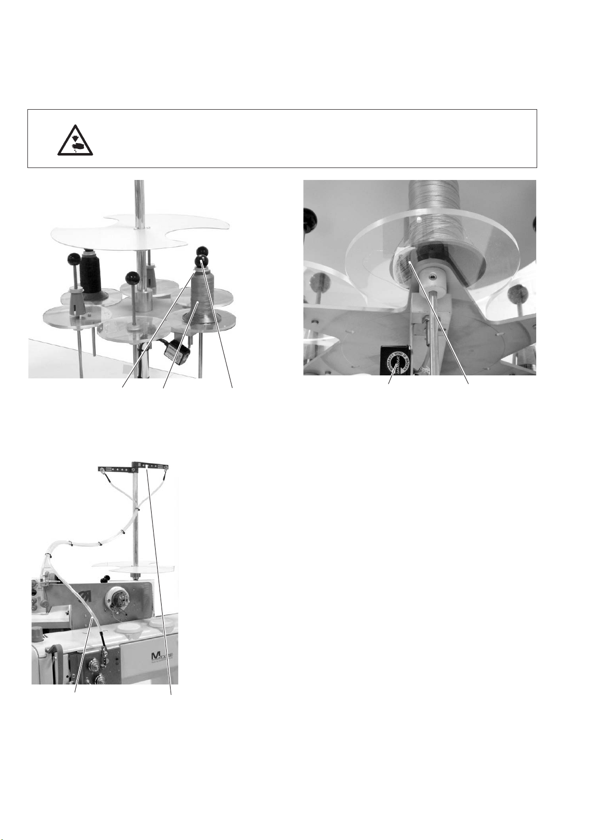
5.1 Threading the needle thread
Caution: Risk of Injury !
Turn off the main switch!
The needle thread may only be threaded with the sewing machine
being switched off.
32 1
Before putting in the needle thread cones they need to be scanned
with the hand scanner.
With thread barcode scanner equipment (optional):
–
Unscrew the ball 1.
–
Put the cone 2 on the stand and make sure that the barcode 4 on
the thread reel can be read by the optional thread barcode
scanner 5.
If the scanner does not recognize the barcode an error message
will appear on the monitor.
–
Tighten the reel with ball 1 and washer 3.
–
Lead the needle thread through the unwinder arm 6.
The unwinder arm must be in vertical position above the thread
reels.
–
Conduct the needle thread through the guiding tube 7.
54
10
76
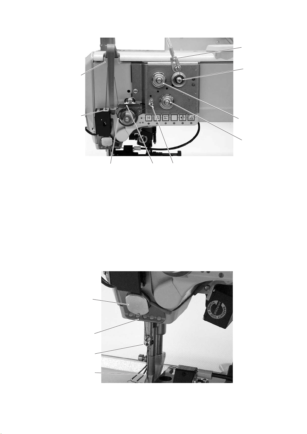
5.1.1 Machines with electronically controlled needle thread tension (ETT)
9
8
765
1
2
3
4
10
–
Conduct the thread through the threading guide 1 and clockwise
around the pretensioner 2.
–
Conduct the thread counter-clockwise around the tensioner 3.
–
Conduct the thread clockwise around the tensioner 4.
–
Conduct the thread through threading guide 5.
–
Pull the thread underneath the thread take-up spring 7 and
conduct it through the thread regulator 6 to the thread lever 9.
–
Conduct the thread through the thread lever 9 and the thread
tension sensor 8.
–
Conduct the thread through the thread clamp 10 and the threading
guides 11 and 12 on the needle bar.
–
Thread the thread into the needle eye 13.
11
12
13
11
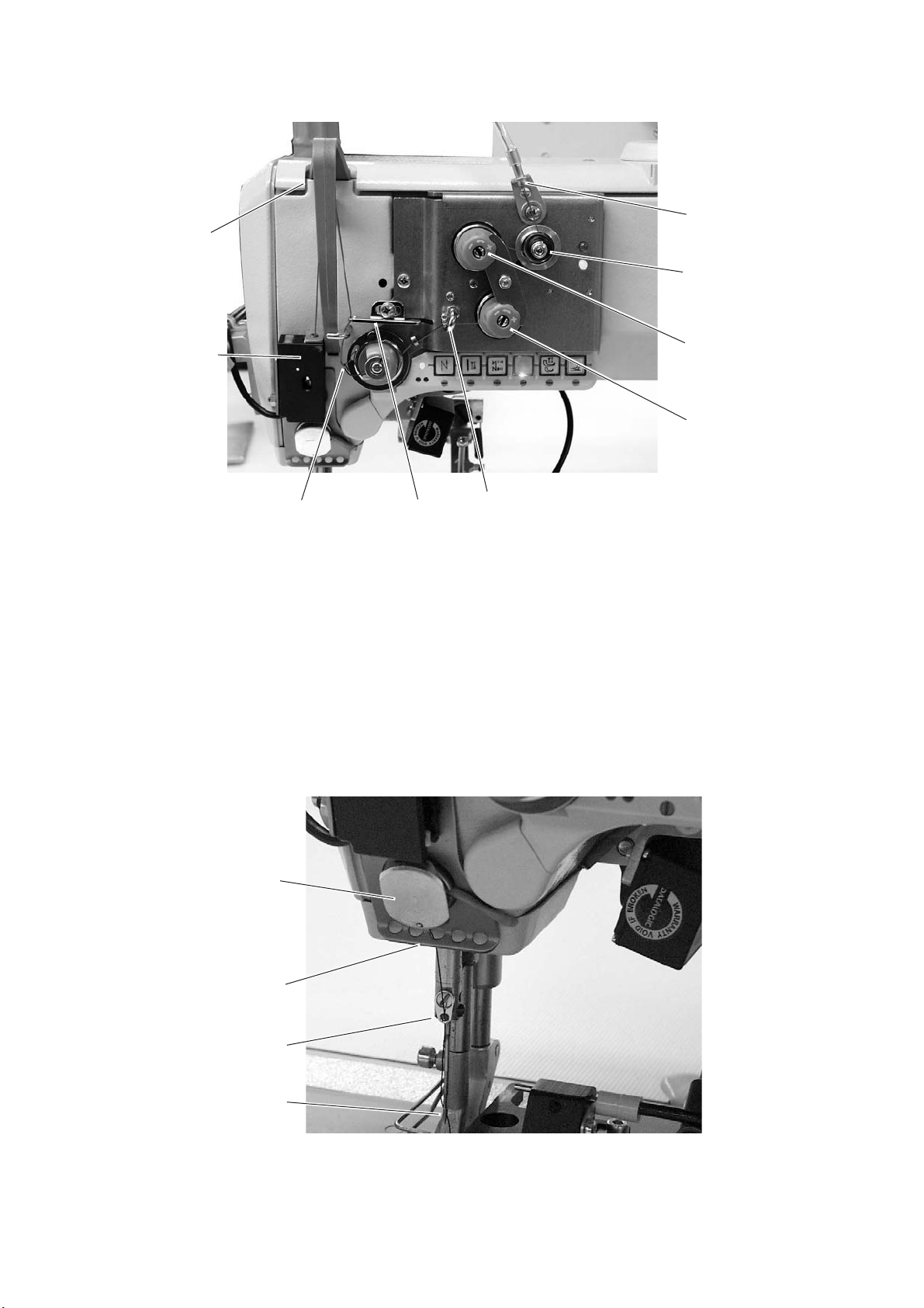
5.1.2 Machines with mechanically set needle thread tension and with electromagnetic
tension release
9
1
2
8
3
4
765
–
Conduct the thread through the threading guide 1 and clockwise
around the pretensioner 2.
–
Conduct the thread counter-clockwise around the tensioner 3.
–
Conduct the thread clockwise around the tensioner 4.
–
Conduct the thread through threading guide 5.
–
Pull the thread underneath the thread take-up spring 7 and
conduct it through the thread regulator 6 to the thread lever 9.
–
Conduct the thread through the thread lever 9 and the thread
tension sensor 8.
–
Conduct the thread through the thread clamp 10 and the threading
guides 11 and 12 on the needle bar.
–
Thread the thread into the needle eye 13.
12
10
11
12
13

5.2 Adjusting the needle-thread tension (mechanically)
The tension is to be set according to the values given by the seat
cover manufacturers. The cross-over point should lie in the center of
the material.
–
The pretensioner 1 is preset.
–
Unscrew the locking plate 3.
–
Set the main tensioner 2 and 4.
–
Mount the locking plate 3 again.
1
2
3
4
5.3 Adjusting the needle-thread tension (ETT)
The thread tension is set via the machine’s software.
13
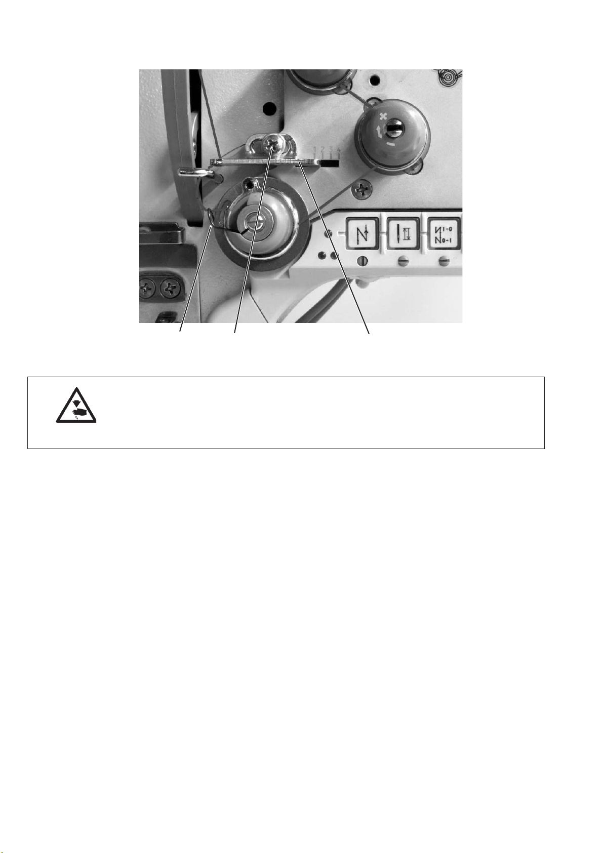
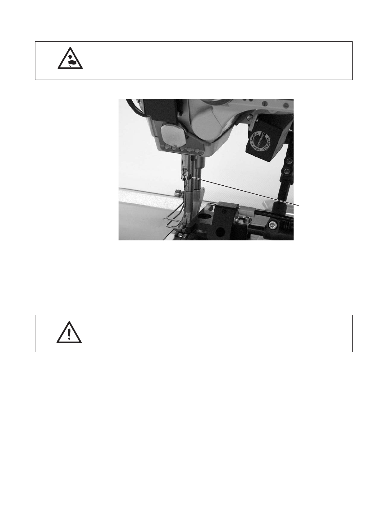
5.4 Adjusting the thread regulator
32 1
Caution: Risk of injury!
Turn off the main switch.
The thread regulator may only be adjusted with the sewing machine
switched off.
The thread regulator 1 controls the quantity of needle thread required
for stitch formation.
The thread regulator must be precisely adjusted for an optimum result.
With correct setting the needle-thread loop must slide with low
tension over the thickest point of the hook.
–
Loosen screw 2.
–
Adjust position of the thread regulator 1.
Thread regulator to the left = more thread
Thread regulator to the right = less thread
–
Tighten screw 2.
Adjustment information:
If the maximum quantity of thread is required, the thread-tensioning
spring 3 must be pulled upwards about 0.5 mm from its lower limit
position. This is the case, when the needle-thread loop passes the
maximum hook diameter.
14
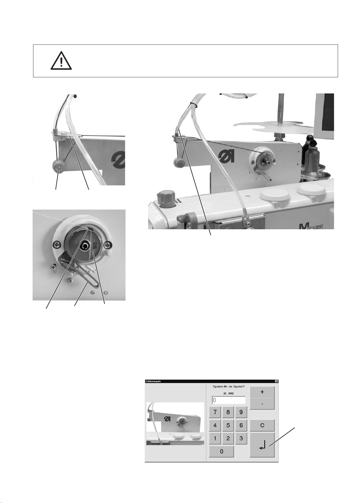
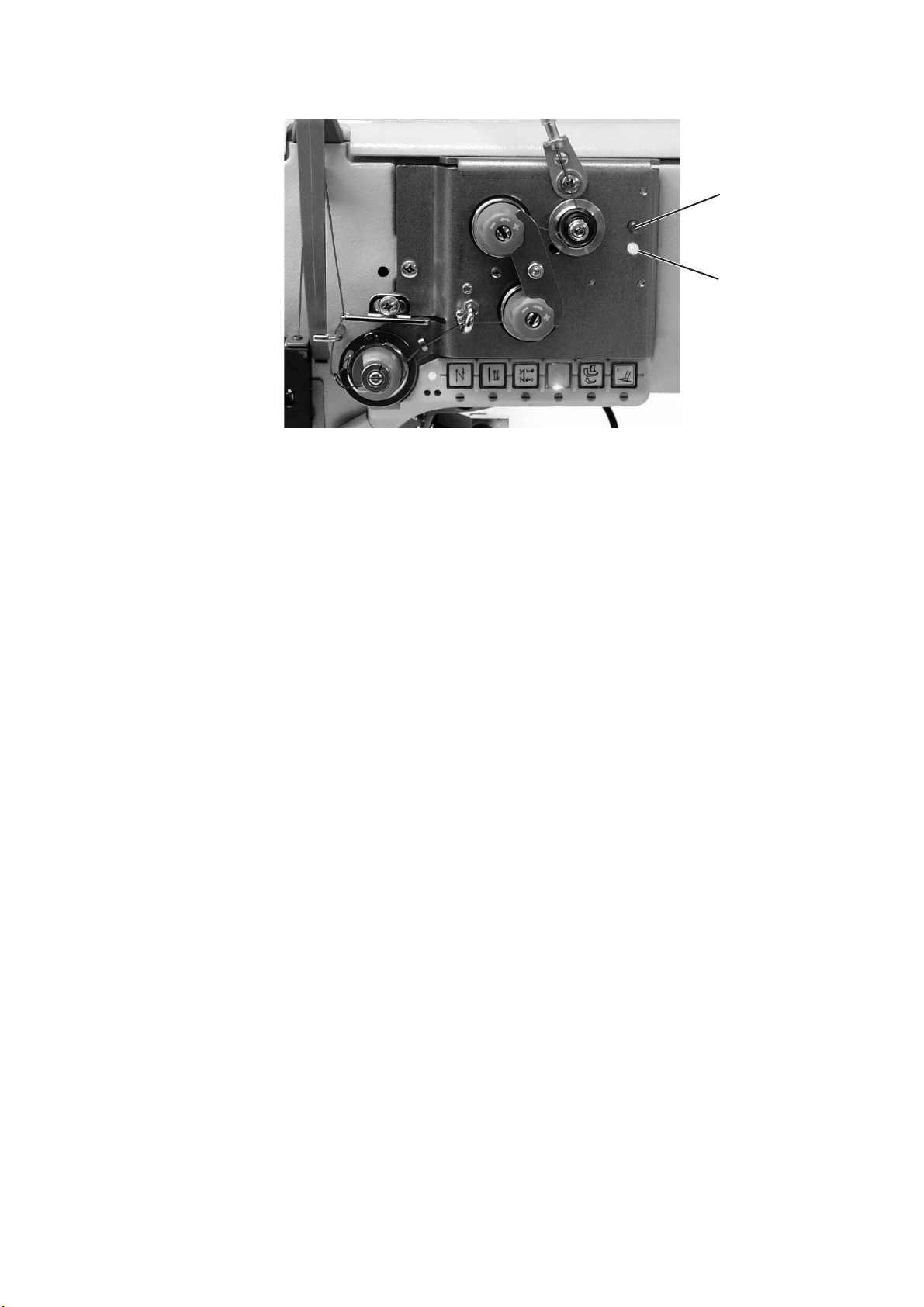
5.5 Winding on the hook thread
ATTENTION!
Only use bobbins that are specially designed for this machine type!
32
65 4
–
1
Put the hook thread cone on the thread stand.
–
Conduct the hook thread through the threading guide on the
unwinder arm and through the tube 1.
–
Conduct the thread counter-clockwise around the tensioner 3.
–
Conduct the thread through threading guide 2 to the bobbin 4.
–
Pull the thread beginning behind the tear-off knife 6 and tear it off.
–
Swivel the winder lever 5 against the empty bobbin.
–
Enter the number of the bobbin via touch screen on the monitor.
When the bobbin is filled, the winding will be automatically
stopped by the winder lever 5.
Caution!
Please make sure that the entered number corresponds to the
bobbin number before actuating the “Return” key.
“Return”
15
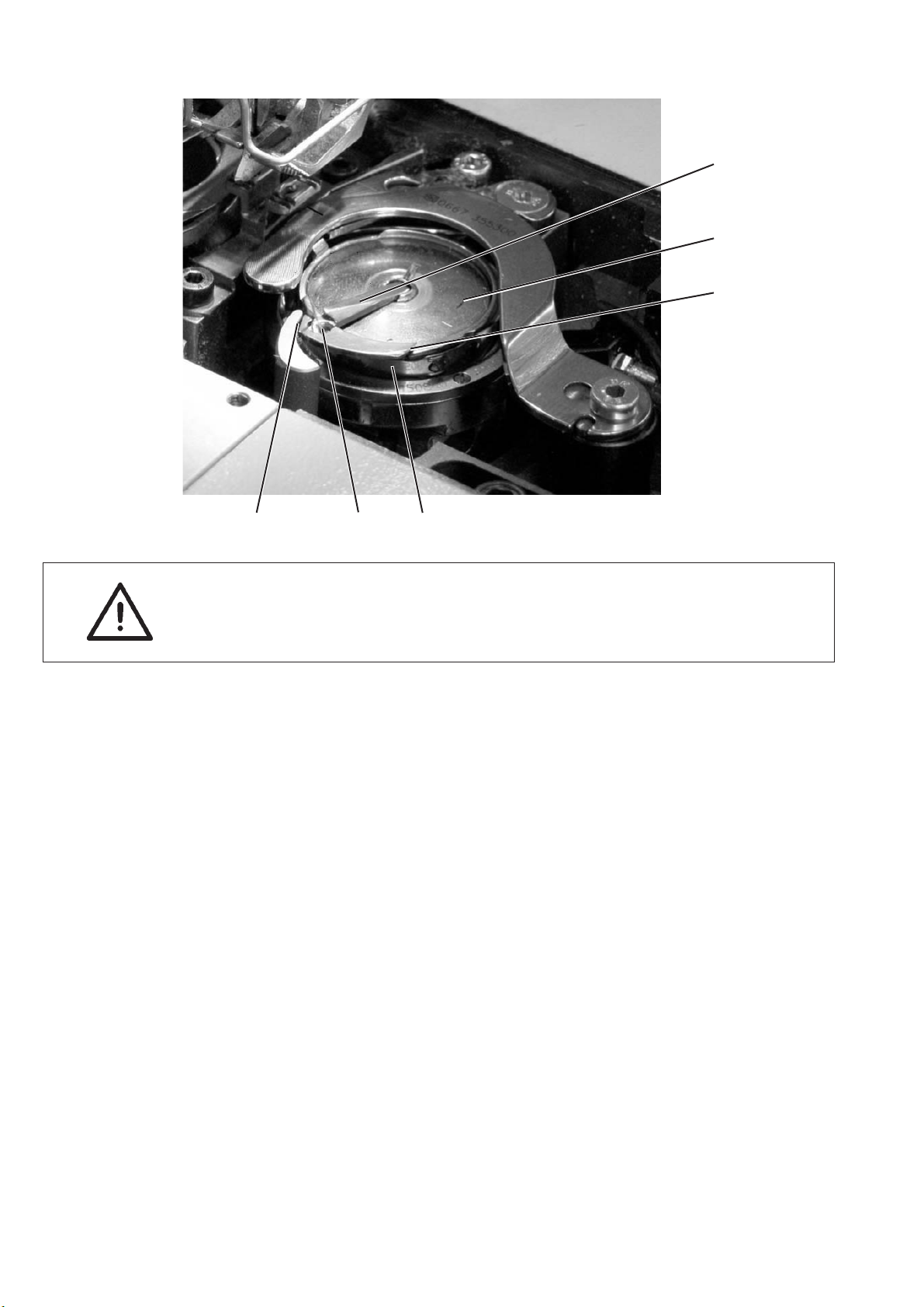
5.6 Threading in the hook thread
1
2
3
654
Caution: Risk of injury!
Turn off the main switch!
The hook thread may only be threaded with the sewing machine being
switched off.
–
Raise up the flap 1 and remove the empty bobbin 2.
–
Insert the bobbin 2 in a way that it moves in counter-clockwise
direction when unwinding the thread.
–
Conduct the thread through slot 3 and underneath the spring 4.
–
Pull the thread through the slot 6 and continue pulling until it
stands out about 3 cm.
–
Close the flap 1 and pull the thread through the thread guiding 5 of
the flap 1.
16
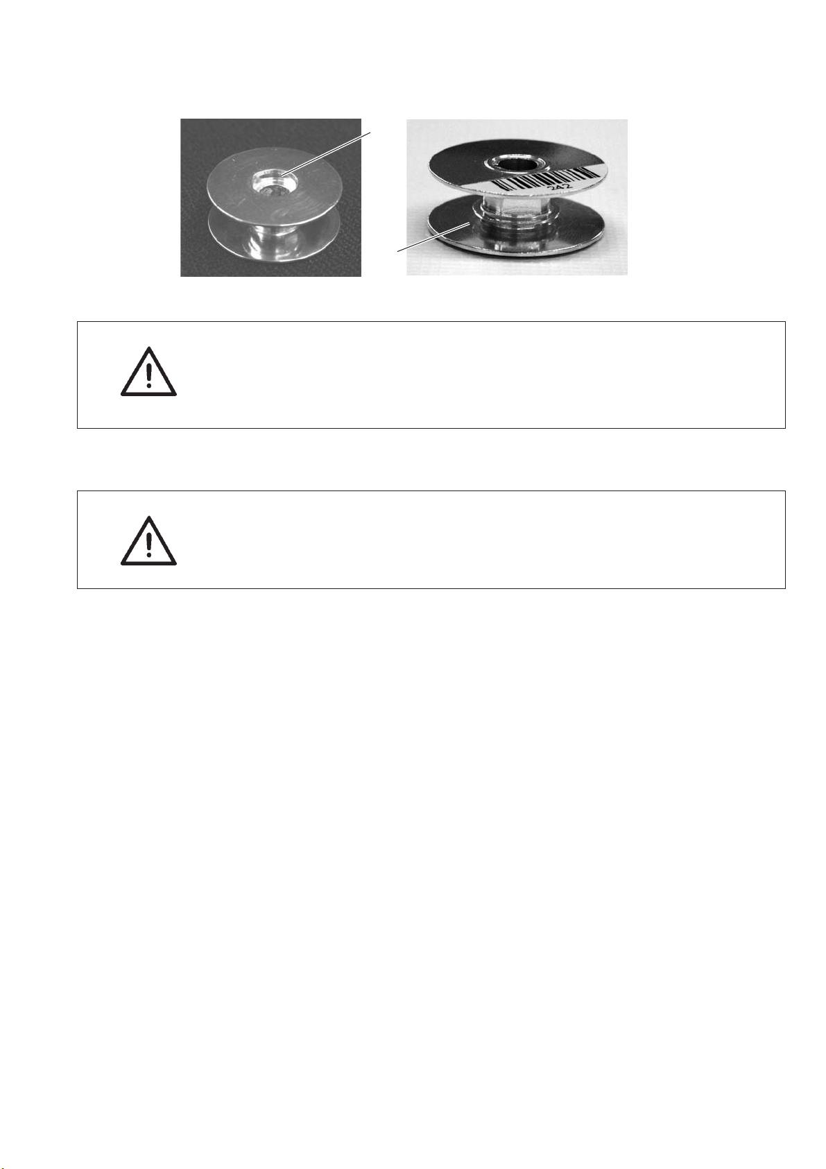
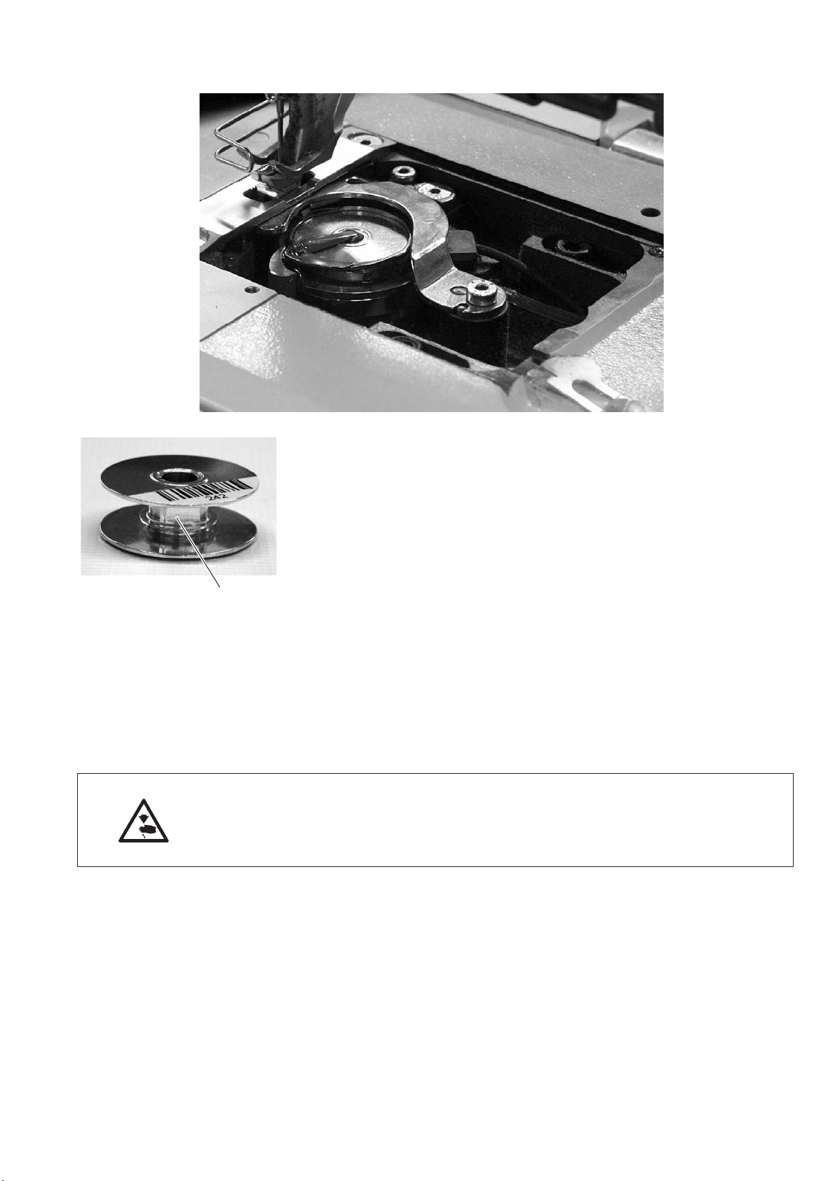
5.7 Inserting the hook thread bobbin with machines equipped with residual
thread monitor
1
2
ATTENTION!
The hook bobbin has to be inserted so that the milling 1 is turned
downwards.
The area around the bobbin housing and the light barrier has to be
cleared of sewing dust !
Winding on the bobbin thread
ATTENTION!
When winding the thread on, the milling 1 has t o be positioned
towards the machine so that the thread is first wound into the
reservegroove2.
17
5.8 Setting the hook thread tension
21
Caution: Risk of injury!
Turn off the main switch.
The hook thread tension may only be adjusted with the sewing
machine switched off.
Setting the tension spring 2
–
Set the tension spring 2 by turning the adjustment screw 1.
Increase the hook thread tension =
Turn screw 1 clockwise
Decrease the pressure =
Turn screw 1 counter-clockwise.
18
5.9 Changing the needle
Caution: Risk of injury!
Turn off the main switch!
The needle may only be threaded in and changed with the sewing
machine being switched off.
1
–
Turn the handwheel until the needle bar is in its upper dead center.
–
Loosen screw 1.
–
Remove the needle.
–
Insert the new needle aligning it, so that the needle scarf points to
the hook and push it to the top as far as it will go.
–
Tighten screw 1.
ATTENTION!
If a needle with a different size is inserted, the settings have to be
adjusted as mentioned in the Service Instructions.
Otherwise missed stitches or thread damage may occur when a
thinner needle is used.
When using a thicker needle the hook tip or the needle may be
damaged.
19
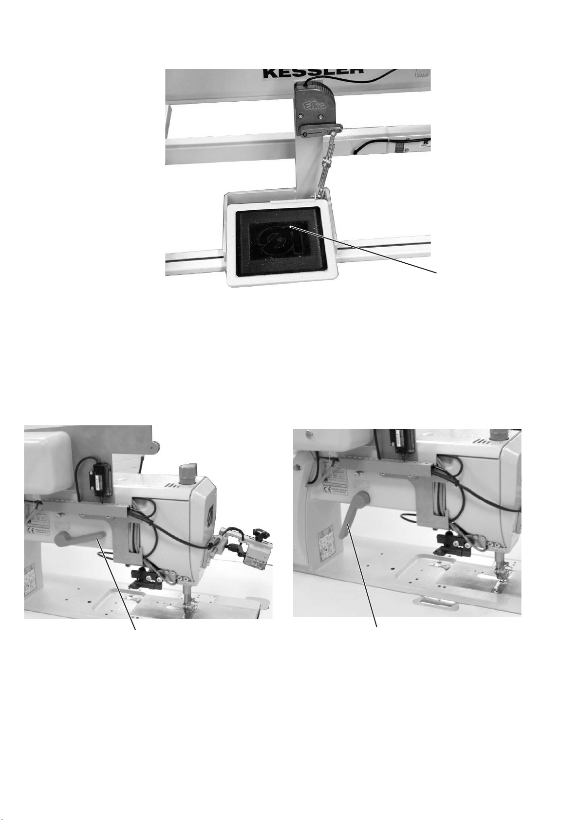
5.10 Lifting the sewing feet
1
The sewing feet can be lifted electro-pneumatically by actuating the
pedal 1.
–
Press the pedal 1 half-way back.
The sewing feet are lifted with the machine at a halt.
–
Press the pedal 1 all the way back.
The thread trimmer is actuated and the sewing feet are lifted.
5.11 Locking the sewing feet in lifted position
1
–
Swivel the lever 1 downwards.
The sewing feet are locked in lifted position.
–
Swivel the lever 1 upwards.
The sewing feet are unlocked.
Or
Lift the sewing feet pneumatically via foot pedal.
The lever 1 then swivels back into its initial position.
1
20
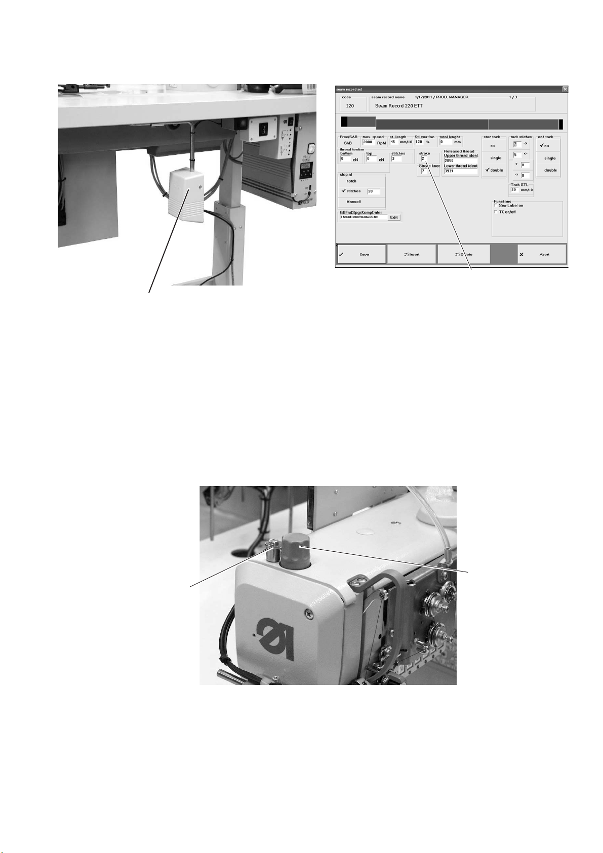
5.12 Setting the sewing-foot stroke
2
The lift stroke 1 of the sewing foot can be set to eight levels (0 – 7) via
the touch screen monitor in the menu item “seam pattern”.
The maximum stroke can be switched on during sewing in free seam
segments by actuating the knee switch 2.
For the documented seam sections this function is disabled.
Important note
Sewing-foot stroke and number of stitches are interdependent.
Through this potentiometer the control unit recognizes the set
sewing-foot stroke and limits the number of stitches. The values are
predetermined by the control unit.
1
5.13 Sewing-foot pressure
4
3
The required sewing-foot pressure is set with the rotary knob 3.
–
Unscrew the locking device 4.
–
To increase the sewing-foot pressure
Turn the rotary k nob 3 clockwise
–
Decrease the sewing-foot pressure
Turn the rotary knob 3 counter-clockwise.
–
Mount the locking device 4 again.
21
5.14 Setting the stitch length
The setting of the stitch length is effectuated via touch screen monitor
in the menu item “seam pattern”.
For each seam section different stitch lengths can be programmed.
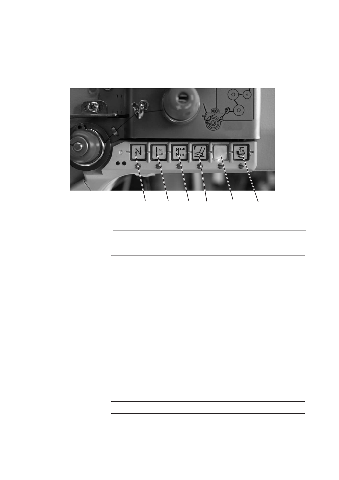
5.15 Switch-key on the machine arm
12345 6
Key Function
1
2
3
Manually sewing backwards.
The machine sews backward stitches as long as
the key 1 is being pushed.
Setting the needle in high or low position.
The function of the key can be defined with the
parameter F-140.
1 = Needle high,
2 = Needle high/low,
3 = Single stitch,
4 = Single stitch with 2nd stitch length/ short
stitch
5 = Needle high, when outside position 2
The factory setting is 1 = needle high.
Activating or suppressing the initial or final
bartack.
If the initial and final bartacks are generally
switched on, the next bartack is switched off by
actuating the key.
If the initial and final bartacks are generally
switched off, the next bartack is switched on by
actuating the key.
22
4
5
6 Quickstrokeadjustment
Forced break-off of the airbag tearing seam
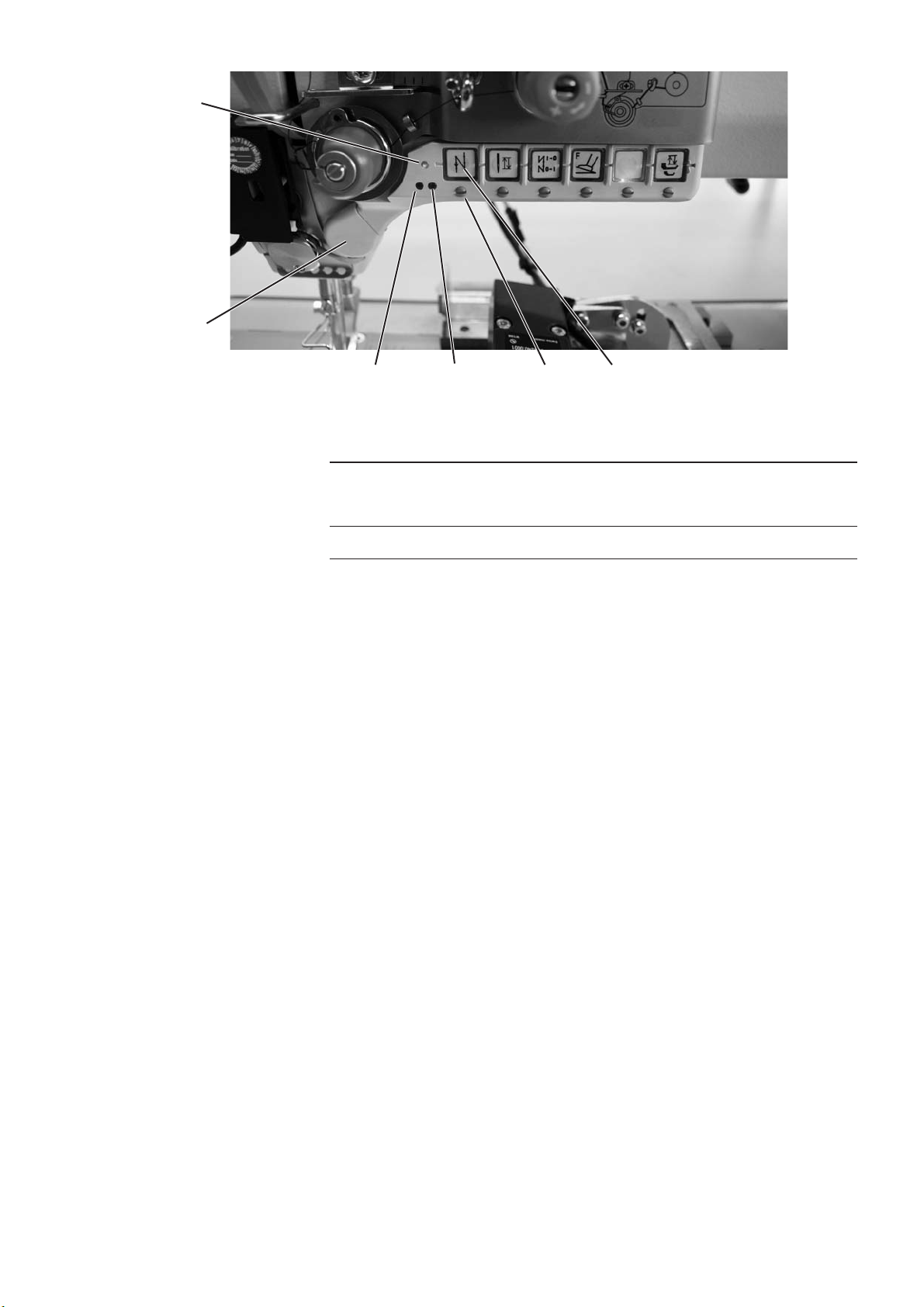
11
10
98 71
LED Function
8and9
11
With the screw 7 under neath the keys the respective function can be
set as “favorite function” for key 10.
–
Select a function.
Example: 1 = Manually sewing backwards
–
Turn in the screw underneath the key 1 and tur n it 90° to the right
(the slot stands vertically).
The function can now be called via both keys 1 and 10.
ATTENTION!
–
Before assigning a new function to key 10 the previous function
must be deactivated.
Display for an empty bobbin with residual thread
monitor
(left/ right bobbin)
LED display “power on”
23
5.16 LEDs on the tension plate
The red LED shines = a tearing seam is sewn
The green LED shines = a non-tearing seam is sewn
red
green
24
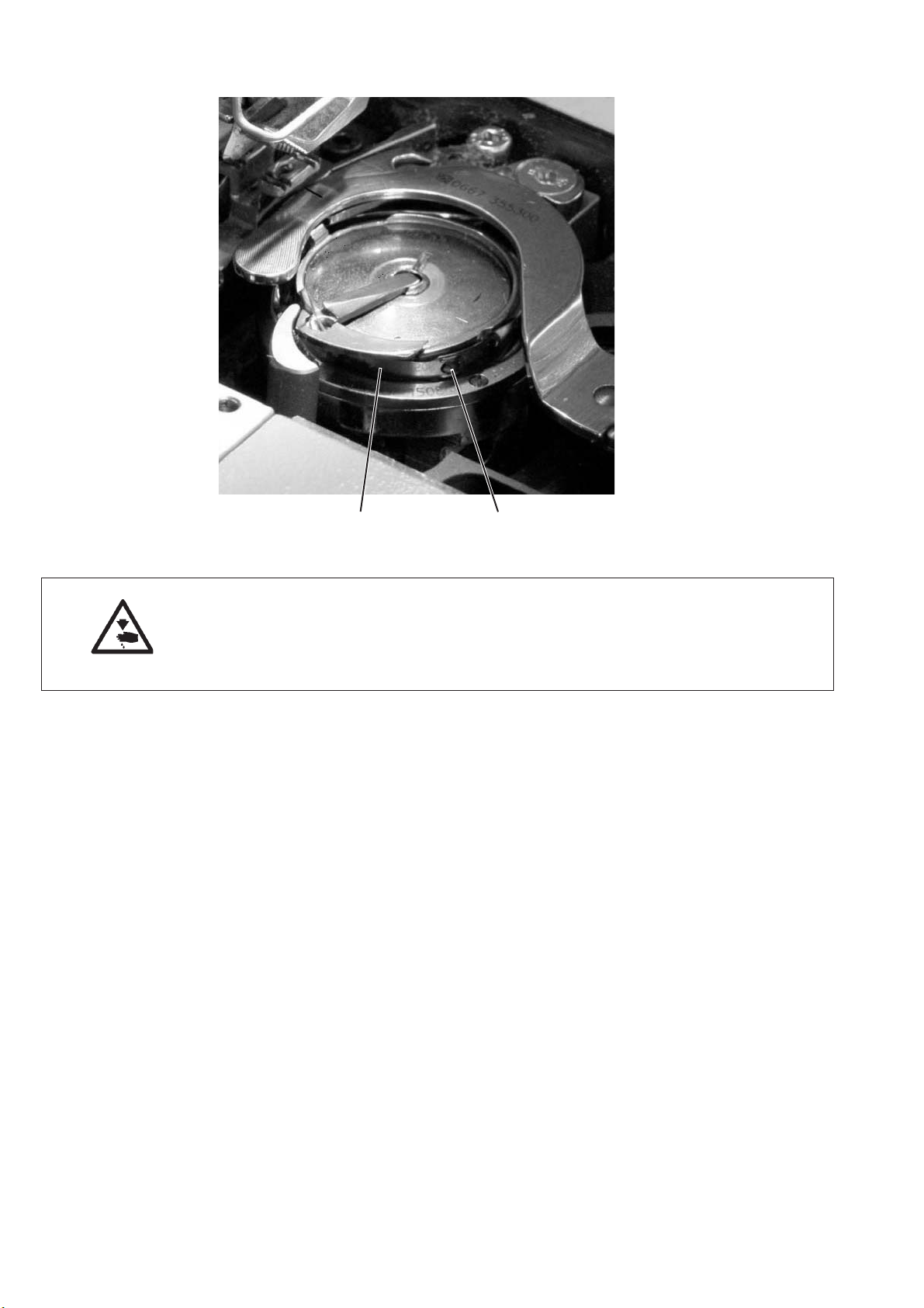
5.17 Residual-thread monitor RFW 20 - 7
The residual thread monitor monitors the quantity of the thread on the
bobbin. A signal is issued on the PC announcing that only a small
quantity of thread remains.
The operator can finish the seam and insert a new bobbin. This way
undesirable repairs or damage to the material are avoided.
Function and operation of the residual thread monitor
1
If the light beam from the light barrier is reflected by the surface 1 on
the bobbin core during sewing, a signal is issued on the PC and the
sewing process will be interrupted.
–
Confirm the message on the PC screen.
–
Release the pedal and then push it forward again. The seam will
be continued. Generally the quantity of thread left in the reserve
groove 2 of the bobbin will be sufficient to finish the seam.
–
At the end of the seam push the pedal back. The thread will be
cut.
–
Terminate the sewing mode with “Back” on the PC.
Caution: Risk of injury!
Turn off the main switch!
The bobbin may only be changed with the sewing machine being
switched off.
–
Replace the bobbin.
–
Reactivate the sewing mode on the PC with “Sew”.
A new seam can be started.
25

ATTENTION!
The hook bobbin has to be inserted so that the milling 3 is turned
downwards. The area around the bobbin housing and the light barrier
have to be cleared of sewing dust !
Important note
If the empty bobbin is not replaced by a full one, the signal will
reappear on the monitor at the end of the next seam.
–
Wind on the bobbin thread.
This process is described in this manual.
3
26

5.18 Electro-pneumatic rapid stroke adjustment
5
Sewing-foot stroke and speed are interdependent. Through the
potentiometer the control unit recognizes the set sewing-foot stroke
and limits the sewing speed. The values are predetermined by the
control unit.
The preset sewing-foot stroke can be switched on during free seam
sequences by actuating the knee lever 1 or the switch 5.
Setting the function of the knee lever
The function of the knee lever is set via the tilt switch 2 (rested or
pushed operation).
Switching on the maximum stroke during sewing
–
Actuate the knee lever 1 .
The sewing-foot stroke is actuated as long as the knee lever 1 is
being kept pushed (pushed operation) or until the knee lever is
actuated the next time (rested operation).
1
2
27

5.19 Uninterruptible power supply (UPS)
The uninterruptible power supply is connected just before the main
switch. It must not be switched off separately so that the accumulator
is loaded permanently.
Switching on the UPS
–
Press the button 1.
The UPS is switched on.
For more details consult the instructions of the manufacturer.
1
5.20 Sewing lamp
1
54 32
Switching on the sewing lamp 1.
–
Set the switch 5 to “1”.
–
Press the switch 3.
The sewing lamp is switched on.
–
The brightness can be altered with the switches 2 (+) and 4 (-).
28

6 Operating the tearing seam visualization
The program is operated by pressing the appropriate buttons on the
touch panel PC 1.
The access to the program is partly protected through three security
levels. (Depending on the security level some buttons on the basic
screen cannot be selected).
1
6.1 Accessing the system
6.1.1 Accessing the system for the first time (DA service personnel)
2
–
Insert the dongle 2 into the USB slot.
–
Enter “Admin” as operator.
–
Confirm with “OK”.
29

6.1.2 Logging in with scanner and barcode
2
–
Press the switch 2 under neath the table top.
The integrated lamp lights up.
–
Scan in the barcode of the operator using the hand scanner 3.
The corresponding security level is activated.
3
30

6.1.3 Logging in via the menu
“Access”
The operator can also log in manually as follows:
–
Press the button “Access”.
The following screen will appear:
“Log in”
“Operator”
and
“Password”
–
Press the button “Log in”.
The following screen will appear:
–
Enter operator and password.
–
Press the “OK” button.
The operator is logged in.
31

6.1.4 Logging out of the system
“Access”
–
Press the button “Access”.
The following screen will appear:
“Log out”
–
Press the button “Log out”.
The following screen will appear:
Note:
Operators with security level 0 are automatically logged off after two
minutes without action.
32

6.1.5 Setting a new operator
Before a new operator can use the sewing unit a user account has to
be set for him. The one setting the account needs to have at least
security level 2.
Note!
In “Setup” the number of digits for the card barcode has to be defined
previously.
–
Log in to the system.
–
Press the button “Access”.
–
Press the button “New”.
The following screen will appear:
–
Enter the name of the new operator and determine his security
level.
–
Enter the personnel number.
–
Enter the password.
–
Repeat the password entry.
–
Press the button “Print BC”.
A barcode for the log-in via scanner will be printed for the new
operator.
–
Press the log-in switch (under neath the table top).
–
Enter the barcode with the hand scanner.
The number will be displayed in the field “Identity number”.
–
Press the “OK” button.
The entries will be adopted.
–
Memorize.
Note:
The log-in system works only with the barcode type 128.
Other barcode types are not accepted by the system.
The contents of the security level authorization barcode can be
checked later on with the hand scanner.
33

6.1.6 Deleting an operator
In order to carry out this operation the user must have the user
privilege of security level 2.
–
Log in to the system.
–
Press the button “Access”.
–
Press the button “Delete”.
The following screen will appear:
–
Select the corresponding operator.
(For example : Operator name Sam)
–
Press the button “Delete operator”.
The following screen will appear:
–
Press the button “Yes”.
The operator will be deleted from the list.
34

6.1.7 Displaying the operators
–
Log in to the system.
–
Press the button “Access”.
–
Press the button “Show users” (Dispaly users).
The following screen will appear:
–
Press “User photo”.
The following screen will appear:
–
Select a user photo from t he list.
–
Press “Open”.
The photo will be loaded.
Note:
The user photos are memorized in the following path:
C:\SABSoft\SystemDB\ -
Format: JPEG
Size: < 150 KB
35

6.2 Seam patterns
Upon pressing the button “seam patter ns” new seam patterns can be
created or existing seam patterns can be edited or deleted.
–
Press the button “Seam rec.” (Seam patter ns).
The following screen will appear:
36

6.2.1 Creating a new seam pattern
–
Press the button “new seam record set” (new seam pattern).
A screen displaying all existing seam patterns and their alteration
status will appear.
21
–
Press “seam par. rec.” (seam patter n code) 2.
The following input screen will appear.
“Return”
–
Enter the seam patter n code.
–
Press the “Return” button.
–
Press “seam record set name” (seam pattern name) 1.
The following input screen will appear.
–
Enter the name of the seam pattern.
–
Press the “Return” button.
The list of all existing seam patterns and their alteration status will
be displayed.
37

–
Press the “OK” button.
An input screen for the number of seam sections will appear.
–
Select the number of seam sections, for example “3”.
–
Press the “OK” button.
The new seam patter n will be displayed.
38

selected
seam section
–
Select the individual seam sections by clicking on them and enter
the corresponding seam parameters.
The selected seam section is displayed with a raised bar.
monitored (red) not monitored
(green)
Parameter Description
Free/SAB Indicates whether a free seam section
or a tearing seam is activated
Max. speed Maximum speed for the current seam
section
St length stitch length in the current seam section
St l corr.fac. Correction of the stitch length depending
on the material
Dist. Length Distance between the two strips on the
sewing material
Thread tension Tolerance range (lower value, top value)
and number of tolerance stitches
Thread tens. Value of power supply in % (only with ETT)
Stop at strip, stitch counting or manually (Pedal – 2)
GB thread ten.
Komp file Selection of a teach-in file (only with ETT)
Lift Stroke Lift stroke of the alter nating sewing feet
Lift stroke knee Lift stroke upon activating the knee lever
(Rapid stroke adjustment)
Bartack stitches Number of bartack stitches
(forwards/backwards)
Sew-in the label Activates the seam scanner
TT on/off Trims the thread at the end of the seam
section
–
After setting the seam parameters for all of the seam sections,
press the button “Save”.
39

Inserting a seam section
–
Select the seam section following the new section that is to be
inserted.
–
Press the “Insert” button.
The following screen will appear.
–
Press the “OK” button.
The inserted seam section 1 will be displayed.
1
–
Select the new seam section by clicking and enter the
corresponding seam parameters.
–
After setting the seam parameters, press the button “Save”.
40

Deleting a seam section
1
–
Press the seam section that is to be deleted.
For example: Seam section 1.
–
Press the button “Delete”.
The following screen will appear:
–
Press the “OK” button.
The seam section will be deleted.
Three seam sections are displayed.
41

6.2.2 Editing a seam pattern
–
Press the “Edit seam par. record” (edit seam patter n) button.
A list of all existing seam patterns and their alteration status will
be displayed.
–
Enter the seam patter n code.
–
Press the “OK” button.
The selected seam patter n will be displayed on the screen.
42
–
Call up the individual seam sections and effectuate the desired
alterations.
–
Press the button “Save”.

6.2.3 Copying a seam pattern
–
Press the button “Copy a seam pattern”.
A list of all existing seam patterns and their alteration status will
be displayed.
–
Enter the code of the seam pattern that is to be copied.
For example: Seam Record 220 ETT.
–
Press “seam pattern code”.
–
Enter a new number for the seam patter n code.
For example: 420
–
Press the “OK” button.
–
Press “seam pattern name” and enter a new name.
–
Press the “OK” button.
The following screen will appear.
–
Press the “OK” button.
The seam pattern 220 has been copied to the new seam patter n
420.
43

6.2.4 Deleting a seam pattern
–
Press the button “Delete seam record set" (delete a seam pattern).
A list of all existing seam patterns and their alteration status will
be displayed.
–
Enter the seam patter n code.
For example: seam 420 from 220
–
Press the button “OK”.
A confirmation request will appear:
–
Confirm the request with “Yes”.
The seam pattern 420 will be deleted.
44

6.3 Data base
The finished seams are recorded and the data are memorized in a data
base.
Via the button “Data base” these recorded data can be displayed,
printed and copied.
1
–
The selection of the desired data takes place via button 1.
“Files”
Each day a new file is created.
With the “Files” button an older file can be displayed.
–
Press the “Files” button.
The following menu will appear:
–
Press the requested file.
–
Press “Open”.
“Print”
If a printer is connected, the selected file can be printed via the button
“Print”.
45

“Copy”
The selected daily file will be copied to a previously determined
directory.
“Help”
A list of the error codes will appear (see chapter 6.6)
“Thread tens”
File that indicates the thread tension values of each individual stitch
within the documented seam sections.
46

6.4 Checking
Via the button “Check” functions are available that serve to secure
and restore files, to inform about sewing materials and sewing
parameters as well as to test, adjust and set-up the integrated sewing
unit.
“Backup System”
When this function is activated all system-relevant settings will be
saved.
–
Press “Backup system”.
The following screen will appear:
47

–
Press the “OK” button.
A selection window will appear.
–
Select the backup location.
–
Press “OK”.
The backup will be saved.
“Restore System”
System-relevant data are imported into the system.
The requested parameters can be set previously.
For the way of proceeding see “Backup System”
48

“Print BC Label”
When this function is activated the label printer will print a barcode
label.
“Backup Record DB”
When this function is activated all data base records of the sewing
station will be saved under the corresponding machine number.
For the way of proceeding see “Backup System”.
“Data import”
Backup files of older software versions will be imported.
For the way of proceeding see “Backup System”.
“Copy dump files”
When this function is activated all dump files will be copied.
For the way of proceeding see “Backup System”.
“Connections”
When this function is activated all connections of the computer will be
listed.
49

“Setup”
When this function is activated system settings can be carried out.
“General settings”
In “General settings” the language is selected, code numbers for the
manufacturer and the machine are attributed, the number of relevant
barcode digits determined and the sewing equipment to be used is
selected.
“Components”
Here the operating equipment or the functions are activated or
deactivated.
Barcode printer For the printing of barcode labels
during sewing
existing / not existing
Protocoll printer (optional) for the printing of
recorded data after sewing
existing / not existing
With batch mode Allows for repeated sewing
after one-time scanning
activated/ deactivated
Scanner needle thread Reading the needle thread barcode
with a fixed scanner
(optional)
existing / not existing
Scanner hook thread Reading the hook thread barcode
with a fixed scanner
(optional)
existing / not existing
Bobbin winder Automatic Bobbin winder
existing / not existing
Step motor Stitch length adjustment via
step motor
existing / not existing
50

Read bobbin no. with
fixed scanner Bobbin identification via
barcode (optional)
existing / not existing
With seam scanner Monitoring of the end label
(optional)
existing / not existing
Cone switch for needle thread Monitoring of the thread cone
via proximity switch.
The bar codes are read with
the hand scanner.
existing / not existing
Cone switch for hook thread Monitoring of the thread cone
via proximity switch.
The bar codes are read with
the hand scanner.
existing / not existing
Multibarcodes Entering additional bar codes
besides the primary bar codes
possible/ not possible
Needle control Regular control / exchange
of the needle
activated/ deactivated
Multibarcode switch Automatic entering of additional
bar codes in batch mode
activated/ deactivated
Save individual stitch data of
SAB-seam Saving the thread tension values
in a TXT-file
on/off
Stitch counting with PC card The stitch counting of t he PC
not of Efka is being considered
activated/ deactivated
Efka decorative bartack
switched on Make selection according to
Efka parameter settings
(decorative or regular bartack)
on/off
Thread tens. individual stitch
check Definition whether the number
of tolerance stitches in a row
should be outside of the tolerance
or be repartitioned
over the whole length
on/off
Calibration control Regular checking of the step
motor and the thread tension
sensor
on/off
Thread tension graphic Visualization of the thread tension
during the sewing process
on/off
51

Thread tension regulator on When using an ETT nominal and
and actual values are compared
and corrected (adjusted)
On/off
Edge detection Optional equipment for the
detection / controlling of the
distance between needle and
material edge
existing / not existing
Bartack stitches progr.
for each SS Allows for different bartack
stitches for the initial and end
bartack in the particular seam
section
On/off
“Values”
In “Values” the scanners to be used are selected, the barcode type for
the card reader is defined and the number of relevant card barcode
digits is determined.
If in the field “Components” the function “Sew-in label separately” has
been activated, the number of stitches for the additional seam can be
determined in this function.
In order to prevent that each thread that gets into the light barrier
simulates a strip, the sensibility of the light barrier can be adjusted in
the function “Strip detection filter stitches”. If the value 2 is entered,
thesizeofthestripmustbeextendedovertwostitchesinordertobe
recognized as such.
By altering the user levels the access rights to the system can be
influenced. The entered values represent the security levels that are at
least required in order to carry out the program functions.
In the field “Lot size” can be entered the number of sewing procedures
that a singular scanning of the entry barcode will allow for.
52

“Bar codes”
Via the “Barcode” field the barcode definitions can be adjusted, saved
or newly loaded.
In order to do so the relevant barcode digits are defined through the
setting of masks.
1 = The digit of the barcode will be read.
0 = The digit of the barcode will be ignored.
Entry of
the nominal
values
1
Changing the barcode definition
–
Press the corresponding barcode row 1
An input screen will appear.
–
Enter the barcode definition.
–
Press the “OK” button.
The new definition is adopted.
–
Press the button “Save”.
Loading a barcode definition
–
Press the “Load” button.
A selection window will appear.
–
Select a file.
–
Press “Open”.
The file will be loaded.
53

Memorizing a barcode definition
–
Press the “Save” button.
A selection window will appear.
–
Enter a file name.
–
Press “Save”.
The definition is memorized.
“Label”
Via the button “Label” the layout of the end label is defined. The
barcode information that will be printed is determined.
Via the button “Define ext. label print" additional information can be
included on the end label.
3
1
2
1 Determining the end label barcode type
see chapter 6.7.
2 Determining the end label layout
see chapter 6.8.
3 Determining the text to be printed
54

“Load”
Via this button a barcode setup file can be loaded.
–
Press “Load”.
A selection window will appear.
–
Press the requested file.
–
Press “Open”.
The file will be loaded.
“Save”
Via this button a barcode definition can be memorized.
–
Press “Save”.
A selection window will appear.
–
Enter a file name.
–
Press “Save”.
The file will be memorized.
“Define extended label printing”
Via this button an extended label print can be edited. With this
function, variable information can be printed on the endlabel.
55

“Path + Network”
Via the button “Path+Netw.” the paths for the memorizing of the
record data base and the system data base as well as the time interval
for automatic saving are determined.
–
Press “Change path”.
The following screen will appear:
56
–
Select the path.
–
Press “OK”. The path will be adopted.
Note:
When using a network connection the path for the automatic copy of
the record data base will be changed to the desired path.

“Threads”
When this function is activated a data base with the thread types that
have been determined for this system will be displayed.
New thread types can be entered and existing thread types can be
edited or deleted.
Important note
When entering a new thread type the Ident-No. has to be entered.
Through the Ident-No. the system recognizes the thread. It is made up
of the predefined digits of the thread barcode.
Entering a new thread type
–
Press the button “New thread”.
The thread type data base editor will appear.
–
Enter the thread barcode.
or
–
Scan the thread barcode.
57

–
Press the button “Scan”.
The following screen will appear:
–
Read the thread barcode with the hand scanner.
–
Press “OK”. The thread barcode is adopted.
–
Enter further thread data and confirm with “OK”.
“Change thread type”
When this function is activated the selected thread type can be
modified.
“Delete thread type”
When this function is activated the selected thread type can be
deleted.
58

“Print DB”
When this function is activated the seam data base is printed (only if a
record printer is connected and has been activated at setup)
“Display DB”
When this function is activated the seam data base will be opened and
all seam parameters will be displayed.
59

“Bobbins”
When this function is activated all registered bobbins will be
displayed. When pressing the button “Delete” selected bobbins can
be deleted.
–
Press the bobbin that is to be deleted.
–
Press “Delete”.
A confirmation request will appear:
60
–
Press “OK”.
The bobbins will be deleted.

“Needle DB”
If during the setup the component „needle control“ has been
activated, the operator will be asked in certain intervals to check the
needle and replace it, if necessary.
These activities are recorded in the needle replacement data base.
–
Press “Exchange”.
The following screen will appear:
–
Press “Checked”.
The following screen will appear:
61

SM Cali
“SM-Cali” and “Cali”
If during the setup the component „calibration control“ has been
activated, the operator will be asked in certain intervals to check the
settings of the step motor and the thread tension sensor or to
recalibrate them.
These activities are recorded in the thread tension and step motor
calibration data base.
Cali
62

“SM”
When this function is activated the stitch length adjustment can be
calibrated and checked.
Checking the stitch lengths
–
Pull the needle thread out of the needle.
–
Put a piece of cardboard 1 under the sewing foot.
–
Press the button “Check 2 mm”.
–
Press the foot pedal.
A predetermined section will be sewn.
–
Measure the stitch length.
–
Proceed as described for the other stitch lengths.
1
63

Calibrating the stitch lengths
–
Pull the needle thread out of the needle.
–
Put a piece of cardboard 1 under the sewing foot.
–
Press the button “Cali. 1”.
The following screen will appear:
–
Press the button “Enter 100 stitches + length”.
The following screen will appear:
–
Press the foot pedal.
A predetermined section will be sewn.
–
Measure the stitch length and enter it with the keys.
–
Press “Return”.
–
Repeat the procedure for “Cali. 2”.
–
Memorize.
64

“I/O”
When this function is activated the inputs and outputs of the system
can be checked.
“Scanner”
When this function is activated the barcode scanners can be tested.
65

“Sewing motor”
When this function is activated all the functions of the Efka DC motor
can be checked.
The preset settings like initial bartack, end bartack, speed, stitch
length and so forth will be transmitted to the control unit via pressing
the “Send” button and a seam will be released.
Note:
These entries can only be carried out via external operating panel of
the type V820.
66

“Thread tension”
This function is for the setting of the thread tension in consideration of
the preset tolerance limits, the sewing speed, the lift stroke as well as
the stitch length and for the checking of the thread tension after a
teach-in process in connection with an ETT.
See chapter 6.6 Tolerance range of the thread tension.
“Thread tens.file”
After pressing this button a thread tension file can be loaded.
67

“Teach-In” (only available with ETT)
During the monitored seam sections the values of the occurring thread
tensions will be compared to a preset tolerance range. If the thread
tensions deviate from the tolerance range more often than desired the
seam will be defined as bad seam.
Adjusting the thread tension to the required tolerance range
The value of the needle thread tension is influenced by several factors
like sewing speed, material, sewing thread, seam section etc. With the
function “Thread tension” the upper and lower limits for the needle
thread tension can be set.
68
Step 1:
Setting the thread tension at the operating point and at the limits.
–
Enter the corresponding values for the tearing seam into the field
for “lower limit”, “upper limit” and “target value”.
(Manufacturer’s data)
–
Enter the maximum speed.
–
Enter stitch length and lift stroke.
–
Press “Set Fa”. The thread tension value is adopted.
–
Check the thread tension using a thread scale.
–
Adjust the value for “Current lifting magnet” correspondingly.
Lower value = Lower thread tension
Higher value = Higher thread tension
–
Also check “Lower limit” and “Upper limit” (Fu, Fo).
–
Press the button “Next step”.

Step 2
Thread tension at the operating point
–
Press “Begin test seam”.
The following screen will appear:
The calculated values for step 2 will be displayed.
–
Press the button “Next step”.
–
Carry out steps 3 and 4.
A screen displaying all registered values will appear.
With the field “File name (NB number)” the calculated values can be
memorized.
69

6.5 Exiting the program
–
Press the button “End”.
The following screen will appear:
70
–
Press the button “PC off”.
The program will shut down and the computer will be switched off.
Note:
If the program is exited with “Yes”, the windows level will be entered
(only possible with security level 2).

6.6 Error codes
EC10000 Acknowledging an error through the supervisor
EC20000 Check the thread tension, currently not in use
EC21000 Forced thread trimming in a t earing seam
EC21500 Received a wrong error message from the Efka motor
EC21600 Received a wrong bobbin thread message from the
Efka motor
EC22000 Forced bartack in a t earing seam
EC22500 Wrong bartack in the seam
EC22600 Wrong stitch counting motor and PC
EC23000 Thread breakage in a tearing seam
EC23500 Thread tension too low in a tearing seam
EC23600 Thread tension too high in a tearing seam
EC25000 Thread breakage within a free seam
EC25500 Thread tension too low in a free seam
EC25600 Thread tension too high in a free seam
EC25700 Edge detection upper limit overran
EC25800 Edge detection lower limit overran
EC26000 Did not read the extra bar code label (additional bar code)
EC27000 Hardware-error, Efka control unit does not react properly
EC27500 Hardware-error, Thread tension measuring device does
not react properly
EC28000 Remained below the allowed stitch area
EC29000 Exceeded the allowed stitch area
EC31010 Incorrect reading of the final label bar code
EC31000 Incorrect reading of the final label bar code with the
manual scanner of the supervisor
EC31500 Wrong final label sewn into the workpiece
EC32000 A bobbin with a non approved thread has been inserted
during the sewing process
EC33000 Bar code printer not ready
ECxxxxxACK The supervisor has acknowledged the error “xxxxx”
ECxxxxxCNT The supervisor has released the further processing
of the workpiece despite the error “xxxxx”
71

6.7 Determining the endlabel barcode
In order to carry out changes in the barcode labeling system, the
operator must have the user privilege of security level 2.
–
Log in to the system.
–
Call up “Check”.
–
Call up “Setup”.
–
Call up “Label”.
1
In field 1 the layout of the endlabel barcode is displayed.
The meaning of the predefined codes is now explained:
D2 Current day (two digits); e.g.: June 9 = 09
M2 Current month (two digits); e.g.: June 9 = 06
Y2 Current year (two digits); e.g.: 2010 = 10
Y4 Current year (four digits); e.g.: 2010 = 2010
J3 Number of days in the year (three digits);
e.g.: February 20 = 051
H2 Current hour (two digits); e.g.: 8:52:13 = 08
U2 Current minute (two digits); e.g.: 8:52:13 = 52
S2 Current second (two digits); e.g.: 8:52:13 = 13
P1 Current personnel number (one digit); e.g.: 1234 = 1
P2 Current personnel number (two digits); e .g.: 1234 = 12
P3 Current personnel number (three digits); e.g.: 1234 = 123
P4 Current personnel number (four digits); e.g.: 1234 = 1234
E1 Current machine number (one digit); e.g.: 567 = 5
E2 Current machine number (two digits); e.g.: 567 = 56
E3 Current machine number (three digits); e.g.: 567 = 567
F1 Manufacturer code (one digit); e.g.: 1357 = 1
F2 Manufacturer code (two digits); e.g.: 1357 = 13
F3 Manufacturer code (three digits); e.g.: 1357 = 135
F4 Manufacturer code (four digits); e.g.: 1357 = 1357
N2 Daily number of pieces (two digits); e.g.: 1234 = 34
N3 Daily number of pieces (three digits); e.g.: 1234 = 234
N4 Daily number of pieces (four digits);e.g.: 1234 = 1234
N5 Daily number of pieces (five digits); e.g.: 12345 = 12345
N6 Daily number of pieces (six digits);
e.g.: 123456 = 123456
72

CP Number of digits and coding are defined by the mask
that is specified under “Prim.barcode mask label”.
1 = the digit will be read; 0 = the digit will be ignored
TU Number of digits and coding are defined by the mask
that is specified under “Needle thread mask label”.
1 = the digit will be read; 0 = the digit will be ignored
TL Number of digits and coding are defined by the mask
that is specified under “Hook thread mask label”.
1 = the digit will be read; 0 = the digit will be ignored
WE Calender week (1 - 53)
WD Weekday from 1 = Sunday to 7 = Saturday
MB Element from multi-barcode
KX Constant sign
LR Identification left/right/L/R/U
LN Identification left/right 0/1/2
SN Seam pattern number
Y1 Year 1-digit
CQ Part I primary barcode
CR Part II primary barcode
R2..R8 Resident counter
V1..3 Machine number from the back
CD, CE Numerics from the file
73

Defining the extended label print
This option allows to additionally print the information listed below on
the endlabel.
The desired information is positioned on the endlabel by means of a
defined program line.
When the extended label print is activated, the information will always
be printed at the predefined position, regardless of the barcode set-up
file that has been
loaded.***********************************************************************
*
* 550-867
* This is the extended label printing setup file
* for customer specific printing
*
* Format of the control lines:
* ————————————————————————* POSX , POSY , FONT , DESCRIBING TEXT , INFO-CODE
* Each line, which has a “*” as first character is
* ignored.
*
*AvaibleInfo-Codes:
* ————————————————* MB1 - MB9 : scanned mutli bar codes 1-9
*ONM:operatorname
* OPN : operator personnel number
* FAB : manufacturer code
* MAC : machine number
* TRN : needle thread barcode
* TRB : bobbin t hread barcode
* DPC : daily piece number
* DNF : daily piece number formatted to 4 digits
* DNT : daily piece number formatted to 3 digits
* ERC : actual e rror code
* SNM : seam record name
* SRN : seam record number 00-99
*DAT:date
*TIM:time
* JDY : Julean Day
* YR2, YR4 : Year with 2 or 4 digits
*DAY:Tag
* MON : Month
* BON : bobbin number
* PB1,PB2,PB3 : parts barcode 1,2,3
* SRT : text from the seam record
* CYN : cycle number
* DT2 : Date : Day, Month, Year but each with 2 digits
* RC2,RC3,RC4,RC5,RC6,RC7,RC8 : resident part counter with 2..8
digits
* GRP : Graphics, Print BMP-file, Filename without “.bmp” instead
DESCR.TEXT
**************************************************************************
74
*40,33,1,,SNM
*85,33,6,,DT2
*85,15,6,,DT2

6.8 Determining the endlabel layout
In order to carry out changes in the barcode labeling system the
operator must have the user privilege of security level 2.
–
Log in to the system.
–
Call up “Check”.
–
Call up “Setup”.
–
Call up “Label”.
1
1
2
3
4
–
Enter the measured height of the label in the field “Label length”.
For example: 25 mm
–
Enter the space between the labels in the field “Gap”.
For example: 3 mm
–
Enter the desired label text into the fields 1.
For example:
Endlabel text 1 = Manufacturer
Endlabel text 2 = Model
Endlabel text left = Left-hand seat
Endlabel text right = Right-hand seat
–
Set the origin for the text coordinates in the fields 2.
–
Set the position of the endlabel text 1 in the fields “Pos. text 1 X”
and “Pos. text 1 Y”.
–
Set the position of the endlabel text 2 in the fields “Pos. text 2 X”
and “Pos. text 2 Y”.
–
Set the position of the barcode in the fields “Pos. BC X" and “Pos.
BC Y”.
–
In the field 3 the desired font is set.
–
With button 4 the set label is printed out.
75

6.9 Adapting barcode definitions
In order to carry out changes in the barcode labeling system the
operator must have the user privilege of security level 2.
–
Log in to the system.
–
Call up “Check”.
–
Call up “Setup”.
–
Call up “Bar codes”.
–
Select the corresponding type in the field “Primary barcode type”.
This barcode is read via hand scanner.
–
Select the corresponding type in the field “Thread barcode type”.
This selection applies to both needle and hook thread.
–
Select the corresponding type in the field “Endlabel barcode
type”.
–
In the following fields masks can be defined to transmit
system-relevant information (entry: “1”) and ignore unimportant
information (entry: “0"): “Prim. barcode identifier A” (barcode for
material and colour), “Prim. barcode identifier B” (barcode for the
top and bottom piece), “Prim. barcode identifier C” (barcode for
theseampattern)and“Prim.barcodemaskL/R”(barcodeforthe
left and right piece).
76

For example
Primary barcode:
·
(read via hand scanner)
11112233001234567890
Primary barcode identification in the field “Prim. barcode identifier
·
A”:
(barcode for material and colour)
11110000000000000000
ID number:
·
1111
If only pieces with the ID number “1111” are to be processed, this
number can be entered in the field “Identifier A set value”. If pieces
with various ID numbers are to be processed, the ”Identifier A set
value" field must remain blank.
–
The “Prim barcode identifier B” field determines whether the piece
is a top, middle or bottom piece.
For example:
Primary barcode:
·
(read via hand scanner)
11112233001234567890
Primary barcode identification in the field “Prim. barcode identifier
·
B”:
00001100000000000000
ID number:
·
22
–
The ID number must be defined in one of the fields “ID piece 1”,
“ID piece 2” and “ID piece 3”. It is not possible to enter the same
ID number in more than one of the fields.
–
In the field “Prim. barcode identifier C” the sewing parameters are
set.
For example:
Primary barcode:
·
(read via hand scanner)
11112233001234567890
77

Primary barcode identification in the field “Prim. barcode identifier
·
C”:
0000011100000000000
ID number: 330
·
Via the ID number the corresponding parameters will be requested
from the data base (here the seam pattern with the number 330).
Note:
Three-digit seam patterns have to be identified with seam pattern
numbers between 100 – 999 (identifying numbers between 001 and
099 are not permitted.
–
The “Prim. barcode mask L/R” determines whether it is a right or
left-hand seat.
For example:
Primary barcode:
·
(read via hand scanner)
11112233001234567890
Primary barcode identification in the field “Prim. barcode mask
·
L/R”:
00000000110000000000
ID number:
·
00
–
The corresponding ID number must be defined in the fields “ID
left” and “ID right”.
Example with two pieces:
11112233001234567890 11112333001234567890
“Prim. barcode identifier A”:
11110000000000000000 11110000000000000000
ID number:
1111 1111
The ID numbers are identical = OK
11112233001234567890 11112333001234567890
“Prim. barcode identifier B”:
00001100000000000000 00001100000000000000
ID number:
22 23
The ID numbers are different = OK.
The piece with the ID number 22 is the top layer, the ID number 23 is
the bottom layer.
78
11112233001234567890 11112333001234567890
“Prim. barcode identifier C”:
00000011100000000000 00000011100000000000
ID number:

330 330
The ID numbers are identical = OK.
The sewing parameters No. 330 will be requested from the data base.
11112233001234567890 11112333001234567890
“Prim.barcodemaskL/R”:
00000000110000000000 00000000110000000000
ID number:
00 00
The ID numbers are identical = OK.
A right-hand seat will be sewn.
The text for a right-hand seat will be printed on the endlabel.
–
Via the field “Prim. barcode mask label” information from the initial
barcode can be printed on the endlabel.
–
Via the field “Mask multi barcode on” is determined how many
additional bar codes (multi bar codes) should be scanned and
memorized.
The desired number of bar codes is realized by selecting the
corresponding digit of the primary barcode.
–
Via the field “Mask multi BC print” information from the
multibarcode of the endlabel can be printed out.
(See information code “MB” chapter 6.7)
79

7 Sewing
CAUTION !
Sewing may only be carried out with a fully-assembled sewing unit on
which all protective devices have been fitted!
2
Switching on the engineered sewing station
–
Switch on the UPS 2.
–
Turn on the main switch 1.
Windows will be loaded and the program “Soll.exe” will be started.
The machine will be tested and initialized.
–
Scan needle thread cone if necessary.
–
Scan hook thread cone if necessary.
–
Insert a bobbin.
1
80

Logging in to the system
–
The log-in takes place by scanning the operator barcode.
–
The operator can also log in manually as follows:
–
Press “Access”.
–
Press “Log in”.
–
Enter operator name and password.
Sewing can only begin if the system start and the scanning of needle
thread cone, hook thread cone and bobbin have been accomplished
faultlessly.
Otherwise the system is not ready for sewing and instead an error
message will be displayed
Sewing
–
Press “Sewing”.
The following screen will appear:
–
Scan in the pieces to be sewn.
Up to 9 additional bar codes can be defined in advance.
All predefined bar codes must be read in.
–
The seam sections can be sewn.
Green seam sections are unmonitored, the diode at the stop glows
81

green, in the red seam sections (monitored segments) the diode
glows red.
–
If an error occurs in a monitored seam section an error message
will be displayed.
–
For operators with the security level 0 sewing is blocked
–
Operators with the security level 1 or 2 can unlock the sewing
process by logging in to the system (via barcode card) and
pressing the field “Continue”.
82

7.1 Seam scanner (optional)
1
A seam scanner 1 can be optionally fixed onto the machine head.
At the end of the seam the scanner checks whether the correct
barcode label has been sewn in.
If the label is not recognized, first a reminder appears and then the
following warning:
Operators with the security level 1 or 2 can scan the label after the
end of sewing manually or print out a new label.
83

8 Maintenance
8.1 Cleaning and Checking
Caution: Risk of injury!
Turn off the main switch.
The maintenance of the sewing machine must only be done when the
machine is switched off.
Maintenance work must be carried out no less frequently than at the
intervals given in the tables (see ”operating hours” column)
Maintenance intervals may need to be shorter when processing
heavy-shedding materials.
A clean sewing machine is a trouble-free sewing machine.
21
Caution: Risk of injury!
Switch off the main switch before tilting the machine head!
Maintenance work Explanation Operating
to be carried out hours
Machine head
- Remove sewing dust,
lint and thread waste
(e.g. with an air blow gun)
Direct drive
Places in special need of cleaning:
- area under the throat plate 2
- area around the hook 1
- bobbin housing
- thread trimmer
- needle area
CAUTION !
Hold the air blow in a way that you avoid the
sewing dust to be blown to the oil sump.
Clean motor ventilation filter 3 (e.g. with an
air blow gun) from sewing dust and thread
waste.
3
8
8
84

3
4
5
Maintenance work Explanation Operating
to be carried out hours
Sewing drive
Clean ventilation filter
(e.g. with an air blow gun).
Check condition and
tension of V-belt 1
Pneumatic system
Check water level in pressure
regulator.
Clean filter cartridge.
Remove lint and pieces of thread from
air-intake openings.
It must be possible to depress the V-belt
by about 10 mm by pressing it with a finger
at its mid-point.
The water level must not rise to the level of
the filter cartridge 3.
- After unscrewing the drain screw 5, the
water under pressure will flow out of
the water separator 4.
Dirt and condensation are separated out by
the filter cartridge 3.
- Disconnect the machine from the
compressed-air supply.
- Unscrew the drain screw 5.
There must be no pressure in the
machine’s pneumatic system.
- Unscrew water separator 4.
- Unscrew filter cartridge 3.
Wash the filter shell and cartridge
with cleaning fluid (not solvent) and
blast clean.
- Re-assemble the maintenance unit again.
8
160
40
500
Check the system for leaks.
500
85

8.2 Repair
When the machine is damaged or parts are wor n please contact:
DÜRKOPP ADLER AG
Potsdamer Str. 190
D-33719 Bielefeld
Phone: +49 (0) 180 5 383 756
Fax: +49 (0) 521 925 2594
E-mail: service@duerkopp-adler.com
Internet: www.duerkopp-adler.com
86
 Loading...