

Page 1

531
CNC Knopfannähautomat
CNC Automat for Button Sewing
Bedienanleitung / Operating Instructions
Aufstellanleitung / Installation Instructions
Serviceanleitung / Service Instructions
1
2
3
Postfach 17 03 51, D-33703 Bielefeld Potsdamer Straße 190, D-33719 Bielefeld
Telefon +49 (0) 5 21/ 9 25-00 Telefax +49 (0) 5 21/ 9 25 24 35 www.duerkopp-adler.com
Ausgabe / Edition: Änderungsindex Teile-Nr./Part.-No.:
02/2011 Rev. index: 01.0 Printed in Federal Republic of Germany 0791 531001
Page 2

Alle Rechte vorbehalten.
Eigentum de r Dürkopp Adler AG und urheberrechtlich ge schützt. Jede, auch auszugsweise
Wiederverwendung dieser Inhalte ist ohne vorheriges schriftliches Einverständnis der Dürkopp Adler AG
verboten.
All rights reser ved.
Property of Dürkopp Adler AG and copyrighted. Reproduction or publication of the content in any
manner, even in extracts, without prior written permission of Dürkopp Adler AG, is prohibited.
Copyright ©
Dürkopp Adler AG - 2011
Page 3

Foreword
This instruction manual is intended to help the user to become familiar
with the machine and take advantage of its application possibilities in
accordance with the recommendations.
The instruction manual contains important information on how to
operate the machine securely, properly and economically. Observation
of the instructions eliminates danger, reduces costs for repair and
down-times, and increases the reliability and life of the machine.
The instruction manual is intended to complement existing national
accident prevention and environment protection regulations.
The instruction manual must always be available at the machine/sewing
unit.
The instruction manual must be read and applied by any person that is
authorized to work on the machine/sewing unit. This means:
– Operation, including equipping, troubleshooting during the work
cycle, removing of fabric waste,
– Service (maintenance, inspection, repair) and/or
– Transport.
The user also has to assure that only authorized personnel work on the
machine.
The user is obliged to check the machine at least once per shift for
apparent damages and to immediatly report any changes (including the
performance in service), which impair the safety.
The user company must ensure that the machine is only operated in
perfect working order.
Never remove or disable any safety devices.
If safety devices need to be removed for equipping, repairing or
maintaining, the safety devices must be remounted directly after
completion of the maintenance and repair work.
Unauthorized modification of the machine rules out liability of the
manufacturer for damage resulting from this.
Observe all safety and danger recommendations on the machine/unit!
The yellow-and-black striped surfaces designate permanend danger
areas, eg danger of squashing, cutting, shearing or collision.
Besides the recommendations in this instruction manual also observe
the general safety and accident prevention regulations!
Page 4

General safety instructions
The non-observance of the following safety instructions can cause
bodily injuries or damages to the machine.
1. The machine must only be commissioned in full knowledge of the
2. Before putting into service also read the safety rules and
3. The machine must be used only for the purpose intended. Use of
4. When gauge parts are exchanged (e.g. needle, presser foot, needle
5. Daily servicing work must be carried out only by appropriately
instruction book and operated by persons with appropriate training.
instructions of the motor supplier.
the machine without the safety devices is not permitted. Observe all
the relevant safety regulations.
plate, feed dog and bobbin) when threading, when the workplace is
left, and during service work, the machine must be disconnected
from the mains by switching off the master switch or disconnecting
the mains plug.
trained persons.
6. Repairs, conversion and special maintenance work must only be
carried out by technicians or persons with appropriate training.
7. For service or repair work on pneumatic systems, disconnect the
machine from the compressed air supply system (max. 7-10 bar).
Before disconnecting, reduce the pressure of the maintenance unit.
Exceptions to this are only adjustments and functions checks made
by appropriately trained technicians.
8. Work on the electrical equipment must be carried out only by
electricians or appropriately trained persons.
9. Work on parts and systems under electric current is not permitted,
except as specified in regulations DIN VDE 0105.
10. Conversion or changes to the machine must be authorized by us
and made only in adherence to all safety regulations.
11. For repairs, only replacement parts approved by us must be used.
12. Commissioning of the sewing head is prohibited until such time as
the entire sewing unit is found to comply with EC directives.
13. The line cord should be equipped with a country-specific mains
plug. This work must be carried out by appropriately trained
technicians (see paragraph 8).
It is absolutely necessary to respect the safety
instructions marked by these signs.
Danger of bodily injuries !
Please note also the general safety instructions.
Page 5

Contents Page:
Foreword and general safety instructions
Part 1: Operating Instructions Class 531- Original instructions
(Version: 02.2011)
1 Product description ........................................... 5
2 Intended use ................................................ 6
3 Subclasses ................................................. 6
4 Additional equipment........................................... 7
5 Supporting frame ............................................. 7
1
6 Technical data
6.1 Technicaldataforthesubclasses.................................... 8
7 Operation
7.1 Threadingneedlethreads......................................... 9
7.2 Adjustingneedlethreadtension..................................... 10
7.3 Openingneedlethreadtensioner .................................... 10
7.4 Adjustingthreadregulator......................................... 11
7.5 Winding hook threads ........................................... 12
7.6 Changing hook thread bobbin ...................................... 13
7.7 Adjusting hook thread tension ...................................... 14
7.8 Changingtheneedle............................................ 15
7.9 Buttonshankshaper............................................ 16
7.10 Adjusting the button clamp hook feet .................................. 17
8 Operating the control unit
8.1 Theoperatingterminal........................................... 18
8.1.1 Thebuttons ................................................. 18
8.2 Userinterface................................................ 20
8.2.1 Menustructure ............................................... 20
8.3 Changingnumberandparametervalues,alternativeselection .................. 21
8.3.1 Changingnumbervalues ......................................... 21
8.3.2 Selectingaparameter........................................... 22
8.3.3 Alternativeselection............................................ 22
8.4 Sewingpattern ............................................... 23
8.5 Energysavingmode............................................ 23
Page 6

Contents Page:
8.6 Mainmenu.................................................. 24
8.6.1 Sewingpatternoperation......................................... 24
8.6.2 Programmingmode............................................. 29
8.6.3 Copyingfunctionforsewingpatternprograms............................ 33
8.6.4 Sewingpatternsequence(sequences)................................. 34
8.6.4.1 Switchingsewingpatternsequenceoperationonandoff...................... 34
8.6.4.2 Sequenceprogrammingmode...................................... 37
8.6.5 Technicianmode .............................................. 38
8.6.5.1 Machineconfiguration........................................... 40
8.6.5.2 Userconfiguration ............................................. 48
8.6.5.3 Servicefunction............................................... 52
8.6.5.4 Freecontours................................................ 64
8.6.5.5 Memory dongle ............................................... 73
8.7 Distributorcircuitboard.......................................... 80
8.8 Errormessages............................................... 82
8.8.1 Errorcategories............................................... 82
8.8.2 Applicationmessages........................................... 83
8.8.3 Machineerrors ............................................... 85
9Sewing.................................................... 89
10 Maintenance
10.1 Cleaning and checking ........................................... 90
10.2 Oillubrication................................................ 91
11 Standard sewing pattern ........................................ 92
12 Clamping feet................................................ 95
13 Repair .................................................... 96
Page 7

1 Product description
The Dürkopp Adler 531 is a CNC lockstitch button sewer. The
existing button patterns are scalable and can be saved in this
modified form. In addition it is possible to enter “free” stitch patterns
(programming). The button sewer is fitted with an automatic sewing
foot elevator, a thread cutter, a thread wiper, an electromagnetic
thread tensioner and an integral DC direct drive.
Technical features:
–
The sewing attachment is driven by an integral positioning drive. A
DAC control unit controls not only the sewing drive but also two
step motors for the X and Y movement to create the stitch
geometry.
–
The maximum size of t he sewing area is 40 mm in the X direction
and 20 mm in the Y direction.
–
The thread is tensioned electromagnetically. It can be freely
configured in specific areas of the stitch pattern.
–
The wick is lubricated centrally for the top part and hook. Two
separate oil reservoirs are available for this that are both supplied
by the top container. There is only one refilling point.
–
A maximum of 50 standard button patter ns are available. These
standard patterns can be modified temporarily (changing the
overall length, width, speed). When the machine is switched off
the modified values of the last used bar tack are retained when it
is switched on again.
–
40 modified standard patterns can also be stored.
–
There is also a maximum of 9 free stitch contours with a total of
3000 dynamically managed stitches available. Thus, for example,
free button patterns can be sewn. The co-ordinates of the free
stitch contours are entered on the operating panel. No other
machine is required.
–
25 sewing pattern sequence programs each with up to 20 sewing
patterns can be created and saved.
–
The accuracy of the co-ordinate entry is 0.1 mm.
–
It is possible to block special button and/or button sequence
programs and/ or modifications so that unauthorized use or
modification can be stopped from the technician level.
–
It is possible to perform an intermediate cut without raising the
button clamp so that a connection thread can be avoided.
–
The control unit can respond to exter nal signals (input) and can
also output signals itself (output).
–
There is a hook thread counter and a daily piece counter.
–
The arm shaft on the button sewer is driven directly by a brushless
direct current motor.
–
Speeds of 0 min
and Y drives) up to 2700 min
–
Service and maintenance work is supported by extensive test
-1
(manual operation with full functionality of the X
-1
can be reached in 100 min-1steps.
programs with which the individual functions can be tested
separately.
1
5
Page 8

2 Intended Use
The Class 531 is a button sewer that can be used as intended to sew
light to medium weight material. Such material is normally material
made out of textile fibers or leather. Such sewing materials are used in
the clothing, domestic upholstery and automobile upholstery industry.
In addition it is possible that even so-called technical seams can be
done with this button sewer. However, here the operator (in
co-operation with DÜRKOPP ADLER AG ) must assess the possible
risks because such applications are on the one hand comparatively
rare and on the other hand there is an enormous variety. Depending
on the results of this assessment suitable precautions may need to be
taken.
Normally only dry material must be processed with this button s ewer.
The material must not be thicker than 9 mm if it is to be compressed
through the lowered sewing feet. The material must not contain any
hard objects. The button sewer must not be operated without an eye
guard.
The seam is normally created with sewing threads made of textile
fibers (cotton thread, synthetic thread or braided yar ns) with the
following dimensions:
Class 531-211 50/3 - 120/3 thread thickness
If you want to use other threads you must also the assess risks arising
from this and if necessary take precautions.
This button sewer must only be installed and operated in dry, tidy
premises. If the button sewer is used in other rooms that are not dry
and tidy other measures will be required that will have to be agreed
(see EN 60204-31: 1999).
As a manufacturer of industrial sewing machines we assume that at
least skilled operating personnel work on our product so that a ll the
normal conditions and if necessary their risks can be assumed to be
known.
3 Subclasses
Cl. 531-211 Single needle lockstitch button sewer with automatic sewing foot
elevation, thread cutter and thread wiper and electromagnetic thread
tensioner.
Fitted with a special button clamp for:
- laundry = button sizes of Æ 7-Æ 18 mm
-DOB&HAKA=buttonsizesofÆ 11 - Æ 40 mm together
with optional button shank shaper unit.
The machine has a shank button rest.
6
Page 9

4 Additional equipment
The following additional equipment is available for the button sewer
531:
Order no. Additional accessories
9822 51 002 6 Sewing light
9822 51 002 7 Tab le cla mp
9870 00 102 1 K lead (socket adapter set for sewing light)
0511 59 001 4 Laser marking (3 lights)
0510 59 003 4 Additional laser light
0511 59 003 4 Manual switch
0531 36 064 4 Button shank shaper unit inc. clamping feet
1
5 Frame
The following supporting frame is available for the button sewer 531.
MG55 40 029 4 Frame package
Table plate size 600 x 1060 mm
Frame height 1160 to 1,305 mm
6 Technical Data
Noises: Lc = 78 dB (A)
Work place-related emission value in accordance with DIN
45635-48-A-1-KL-2
Speed: 2,700 min
Material: G1 DIN 23328 2 layers
-1
7
Page 10

6.1 Technical data for the sub classes
Subclass: 211
Sewing stitch type: 301
Hook type: Oscillating hooks
Needle system: DPx17 (135x17)
Needle thickness: [ Nm] 80 - 110
Needle thickness [ Nm] 90
standard:
Thread thickness: 50/3 - 120/3
Stitch length: [mm] Depending on seam construction
Max. speed [min-1] 2700
Clamp elevation [mm] 9
On delivery
maximum 13
Sewing area [mm]
max. in X direction: 40
max. in Y direction: 20
Number of standard 50
button patterns
Number of patterns that can be saved
and/or modified 40
Number of sewing pattern
sequence programs 25
Number of sewing patterns per
sewing pattern sequence program 20
Number of free max. 9
seam contours
Soft start can be switched on and off
Sewing drive: DC motor
Rated voltage: [V] 1 ~ 230V/ 50/60 Hz
Power rating: [ kW ] 0.45
8
Page 11

7 Operation
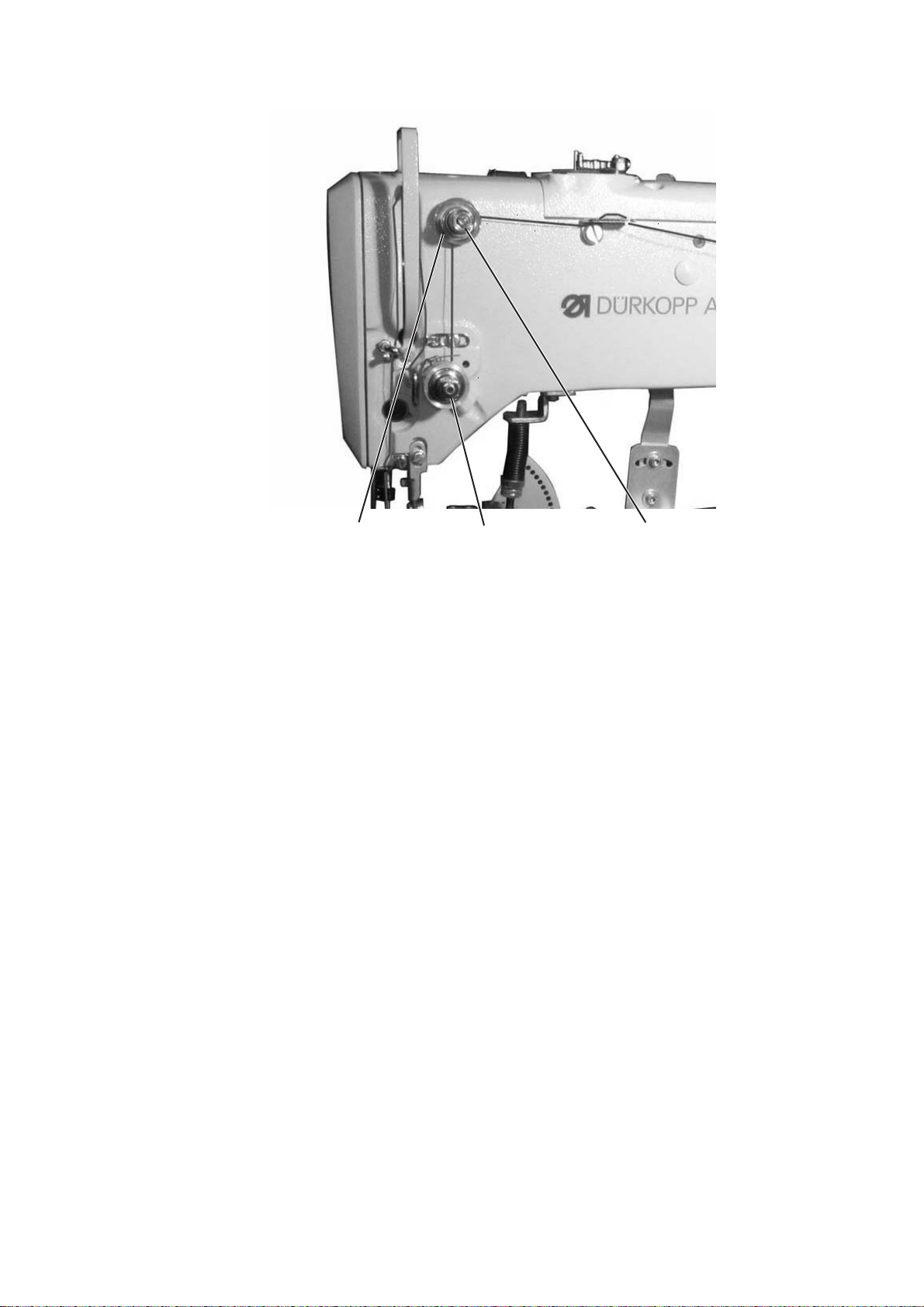
7.1 Threading needle threads
Caution, danger of injury!
Switch the main switch off.
Only thread needle threads when the button sewer is switched off.
–
–
Put reels of thread onto the thread stand and run t he needle and
hook threads through the feed arm.
The feed arm must be vertically above the thread reels.
Thread needle threads as shown in the following illustration
.
1
9
Page 12
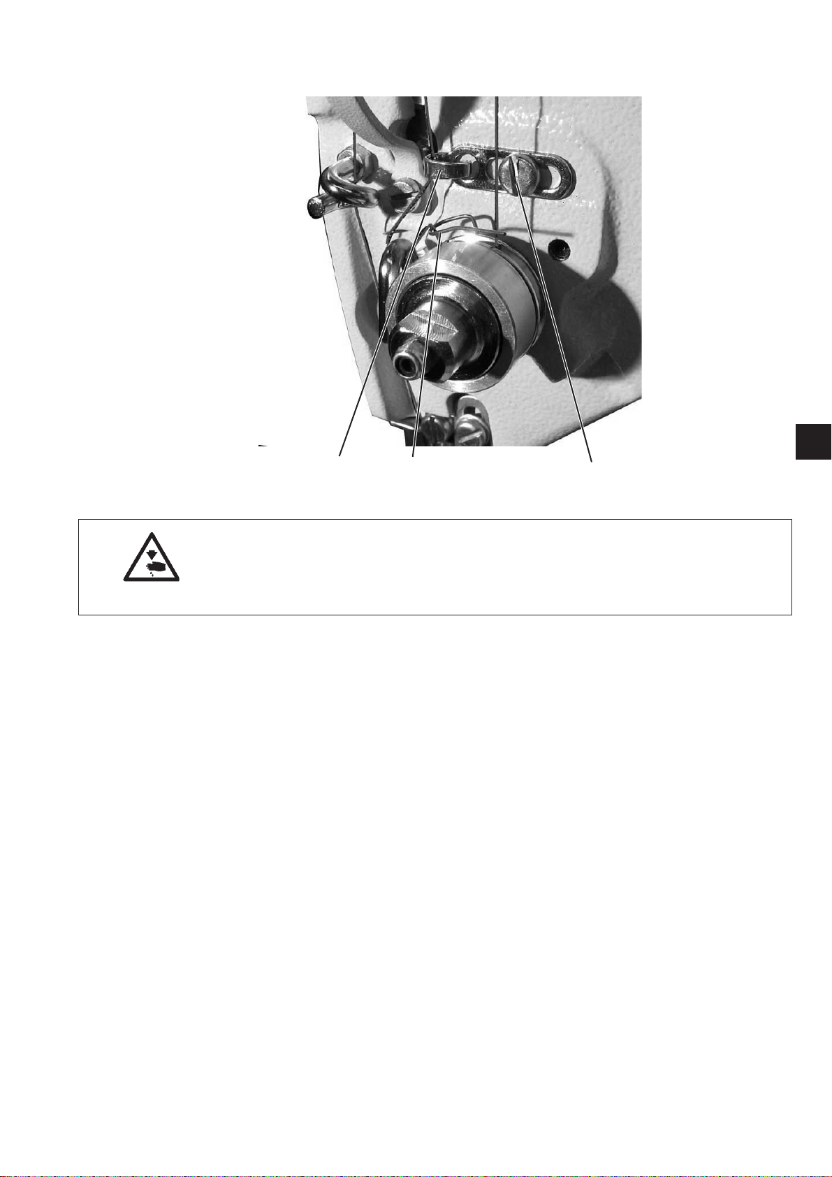
7.2 Adjusting needle thread tension
32 1
Pre-tensioning 3
When the main tensioner 2 is open a slight residual tension on the
needle thread is required. The residual tension is created by the
pre-tensioner 3.
At the same time the pre-tensioner 3 affects the length of the cut
needle thread end (starting thread for the next seam).
–
Shorter starting thread:
Turn the knurled nut 1 clockwise.
–
Longer starting thread:
Turn the knurled nut 1 anti-clockwise.
Main tensioner 2
The main tensioner 2 must be set as low as possible.
The threads should intertwine in the middle of the material.
If the thread tensions are too great this could lead to unwanted
crimping and thread tearing with thin material.
–
Adjust the main tensioner 2 so that an even stitch pattern is
achieved.
To increase tension = turn the knurled nut
clockwise
To reduce tension = turn the knurled nut
anti-clockwise
7.3 Opening needle thread tensioner
Automatic
The needle thread tension opens automatically when the thread is cut
and when the material clamping feet are raised.
10
Page 13
7.4 Adjusting thread regulator
1
32 1
Caution, danger of injury!
Switch the main switch off.
Only adjust the thread regulator when the button sewer is switched
off.
The thread regulator 3 adjusts the amount of needle thread required to
form the stitch.
Only a precisely adjusted thread regulator guarantees optimum
sewing results.
If the adjustment is correct the needle thread loop must slide over the
thickest part of the hook with slight tension.
–
Undo screw 1.
–
Change the position of the thread regulator 3.
Thread regulator to the left = greater needle thread quantity
Thread regulator to the right = smaller needle thread quantity.
–
Screw up screw 1.
Adjustment note:
If the greatest amount of thread is required the thread take up spring
2 must be pulled down about 0.5 mm from its final upper position.
This is the case if the needle thread loop passes the maximum hook
diameter.
11
Page 14

7.5 Winding hook threads
:1
: 2000
:35
: 3.4/ 3.4
/ :6-6
/Ó: 0
: Aus
: Ein
5
1
4
3
2
6
–
Put the bobbin on the bobbin winder 4.
–
Pull the thread through the guide 2 and round the tensioner 1 .
–
Wind the thread anti-clockwise about 5 times round the coil
bobbin.
–
Push the bobbin lever 3 onto the bobbin.
–
Sew
The bobbin lever ends the procedure as soon as the bobbin is full.
–
After winding break the thread on the thread clamp 5.
Note!
Should the thread be wound without sewing
the thread winding mode can be switched to in the “Special functions”
sub menu.
12
When the thread winding mode is switched on the sewing motor can
be started with the pedal or the manual switch regardless of the
sewing area drive (here unthread threads on the thread lever).
For settings see Section 8.5.1 “Thread winding mode”.
Page 15

7.6 Changing hook thread bobbin
1
7
4
2
5
6
2
3
1
Caution, danger of injury!
Switch the main switch off.
Only change the hook thread bobbin when the button sewer is
switched off.
Removing the empty bobbin
–
Pull the hook cover 3 downwards.
–
Lift up the bobbin case latch 1.
–
Remove bobbin case 2 with bobbin 6.
–
Take the empty bobbin out of the bobbin case 2.
To insert a full bobbin
–
Insert a full bobbin into the bobbin case 2.
–
Thread the hook thread through slit 5 under the tensioning spring
7 into the hole 4.
–
Pull about 2.5 cm of hook thread out of the bobbin housing.
The bobbin must tur n in the direction of the arrow when the thread
is being pulled out.
–
Replace the bobbin case 2.
–
Close the bobbin case latch 3.
13
Page 16

7.7 Adjusting hook thread tension
1
2
3
Caution, danger of injury!
Switch the main switch off.
Only adjust the hook thread tension when the button sewer is
switched off.
The required hook thread tension should be created by the tensioning
spring 1. The bobbin case 3 should drop slowly under its own weight if
the threaded hook thread is to be held fast.
Adjusting the tensioning spring
–
Remove the bobbin case 3 and the bobbin.
–
Change the tensioning spring 1 with the adjustment screw 2 until
the required tension is reached.
–
Replace the bobbin case.
14
Page 17

7.8 Changing the needle
2
21
Caution, danger of injury!
Switch the main switch off.
Only change the needle when the button sewer is switched off.
–
Undo screw 1.
–
Push the new needle into the hole in the needle bar 2 until it can
go no further.
CAUTION!
The hollow channel 3 on the needle must point towards the hook.
–
Screw up screw 1.
CAUTION!
After changing to a different needle thickness the distance between
the hook and the needle must be adjusted (see Service instructions).
3
1
1
15
Page 18

7.9 Button shank shaper (optional)
1
The button clamp on the button sewer is fitted with a button shank
shaper 1.
Setting the shank length
–
To change the s etting of the button shank shaper 2:
downwards = shank becomes shorter
upwards = shank becomes longer.
2
16
Page 19

7.10 Adjusting the button clamp hook feet
21
Caution, danger of injury!
Take great care when adjusting the button clamp when the button
sewer is switched on.
The button should be pushed as lightly as possible between the hook
feet on the button clamp and can be aligned.
But the button must be securely clamped so that it cannot turn when
it is inserted into the material.
Stop 4 adjusts the amount the hook feet open.
–
Switch the button sewer on.
The button clamp lifts up.
–
Put the button to be sewn on between hook feet 1 and 2.
–
Undo knurled nut 3.
–
Move the stop towards the screw 5.
–
Tighten knurled nut 3.
–
Check whether the button can be inserted easily and aligned.
543
1
17
Page 20
8 Operating the control unit 531
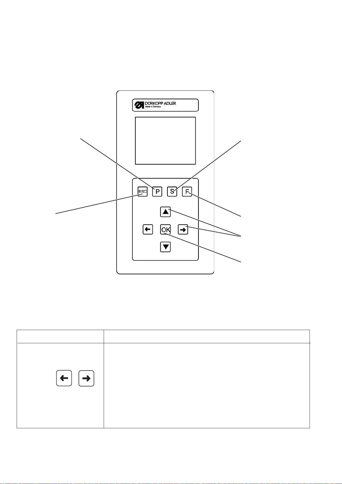
8.1 The operating terminal
An operating terminal with an LCD display and function buttons is
used for entering and outputting data.
P button: S button:
Programming mode Sequence
programming
ESC key F key
Technician mode
Cursor keys
OK key
8.1.1 The buttons
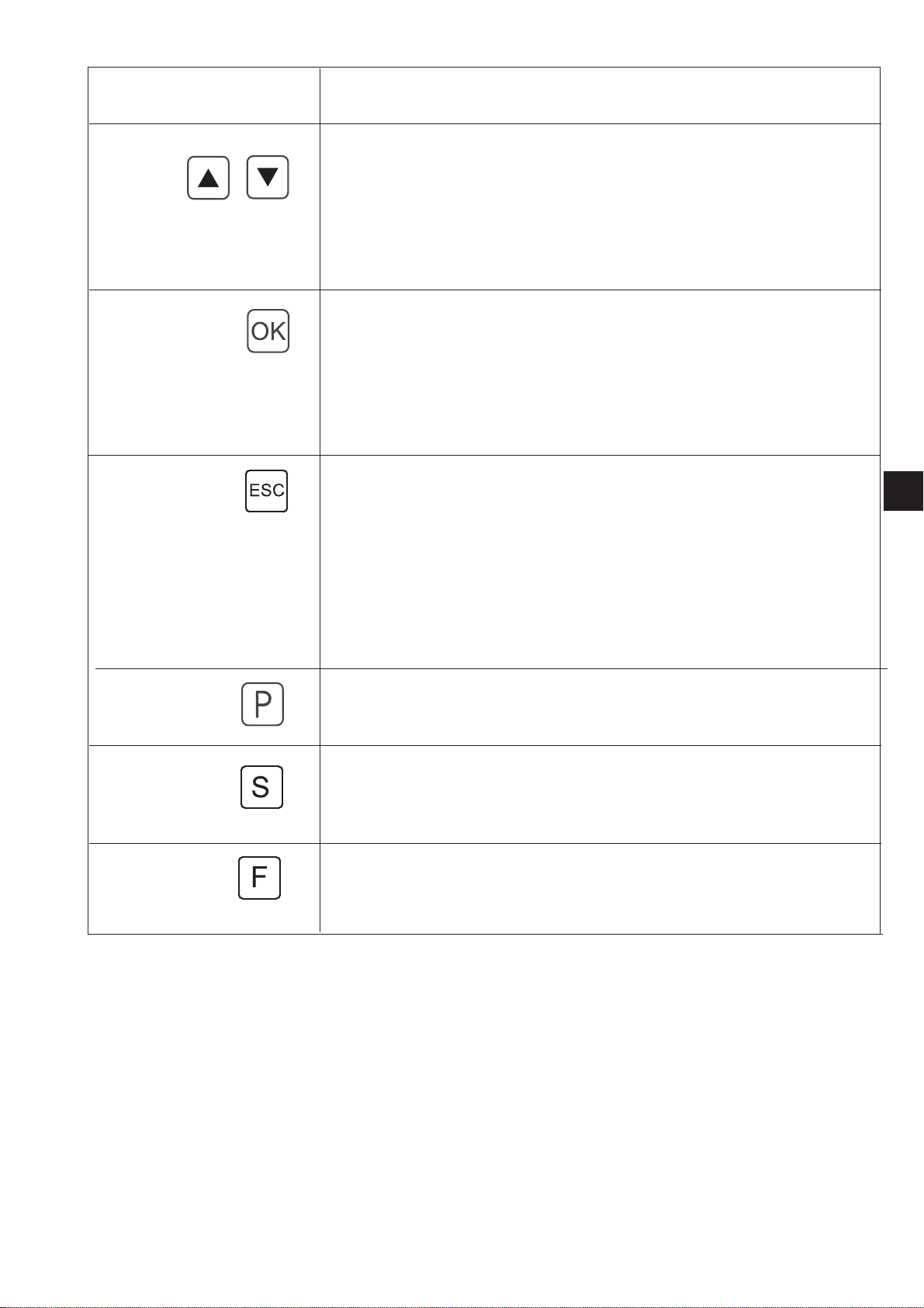
Function button Function
Cursor keys
If no input field is selected:
Press “ï” to get back to a sub menu in the higher menu.
If an input field is selected:
Switch between the positions (not when selecting the sewing patter n
or sequences).
18
In sewing mode with sequence mode:
Switch to the next or previous sewing patter n.
Page 21
Function button Function
If no input box is selected:
Switch between the rows in the menus.
The selected line is shown inversely.
If an input field is selected:
Increase or reduce the value of the relevant position by one or with
functions with several alter native options switch between the
parameters.
OK button If no input field is selected:
Select the input field.
The value can be changed with the “ñ “and“ò ” keys.
If an input field is selected:
The set value will be applied.
If the clamping foot has been lowered by pressing OK + F:
The test sequence starts.
ESC button If the test functions have started (Multitest / 180° disc):
You go back to the selection menu.
If an input box has been selected:
An entry is cancelled.
The previous value is retained.
1
At technician, programming level
The control unit switches to sewing mode.
In sewing mode
raise clamping foot and cancel sewing procedure.
P button The control unit switches from sewing mode to programming mode.
In this mode changed stitch patterns can be saved under a new
program number.
S button The control unit switches from sewing mode or s ewing pattern
programming mode to the sequence programming mode.
In this mode new sequences can be created or existing ones modified.
F button The control unit switches from sewing mode to technician mode.
This mode can only be selected by entering a code.
In this operating mode basic machine parameters can be set and
diagnosis and setting programs can be called up.
19
Page 22

8.2 User interface
8.2.1 Menu structure
on
ESC key F key
Turn the main switch
F button
Service
menu
Codes 1
Sewing mode
P button Codes 1
Button
ESC
Programming mode Technician mode
S button
S button
P button
Sequence programming mode
Calling up the service menu
–
Press F and hold it down.
–
Turn the main switch on.
The control unit is initialized.
After a short time the window to enter the number code appears.
–
Enter the number code (Code 1 see Section 8.6.4).
The display changes to the service menu (see Section 8.6.4.3).
20
Page 23

Calling up technician mode
:1
: 2000
:35
: 3.4/ 3.4
/ :6-6
/Ó: 0
–
Switch the main switch on.
The control unit is initialized.
The sewing menu appears on the screen.
–
Press “F”.
–
Enter Code 1 (see Section 8.6.4).
–
Press “OK”.
The display changes to technician mode.
8.3 Changing number and parameter values, alternative selection
8.3.1 Changing number values
1
–
Select the required row by pressing “ñ”or“ò”.
–
“Press OK .
The selected number value is indicated by a flashing cursor.
–
Press “ï”or“ð” to toggle between the places.
Press “ñ”or“ò ” to increase or reduce the value of the selected
position.
–
“Press OK.
The value currently set is applied
or
–
“Press ESC.
The original value is retained.
Note
All values can only be changed within the minimum and maximum
values.
21
Page 24

8.3.2 Selecting a parameter
:1
: 2000
:35
: 3.4/ 3.4
/ :6-6
/Ó: 0
With some parameters it is possible to select settings that cannot be
modified.
–
Select the required row with the parameters to be changed by
pressing “ñ”or“ò ”.
–
Press OK.
–
Press “ñ“or“ò ” to switch between the specified options.
Example:
Sewing pattern number.
8.3.3 Alternative selection
–
Press OK.
The parameter currently set is applied.
or
–
“Press ESC.
The original parameter is retained.
Some menu items can be selected as an alternative to each other.
The current selection is indicated by a tick (...ü).
When selecting another alter native the mark on the current selection
is cancelled and the new menu item is indicated.
Items that can be selected as an alternative are visually separated
from the other menu items by a dividing line.
22
Page 25

8.4 Sewing pattern
Energiespar-Modus
There are three different sewing pattern types available for the button
sewer 531.
Fixed standard sewing pattern (type 1) (See section 11)
·
The length, width and sewing speed parameters can be changed
in sewing mode. The laser marking lights can be switched on and
off. The changes are saved.
After selecting another sewing pattern the changes are lost,
however.
Sewing pattern numbers 1 - 50 are available for this sewing
pattern that cannot be deleted or overwritten.
Programmable sewing pattern (type 2)
·
Fixed standard sewing patterns can be changed at programming
level (length, width, sewing speed, laser light 1 - 8) and saved
under a new program number.
Sewing pattern numbers 51 - 90 are available for this sewing
pattern that can be changed or overwritten.
Free seam contours (type 3)
·
Sewing pattern numbers 91 - 99 are available for these seam
contours. How to create free seam contours is described in
Section 8.6.5.4.
The length, width and sewing speed parameters can be changed
in sewing mode. The laser marking lights can be switched on and
off. The changes are saved.
When another sewing patter n is selected the changes are lost,
however.
1
8.5. Energy saving mode
25 sewing pattern sequence programs each with up to 20 sewing
·
patterns for each sewing pattern sequence program can be
created and saved.
The energy saving mode is selected after a time that can be set (1 - 60
minutes) or switched off completely (0 minutes) by using t5 in the
Machine configuration/timesmenu.
When this is selected the clamping foot is lowered to save energy and
thus reduce the amount of heat developed too.
The set time expires if no user entries are made via the control panel,
pedal or manual switch.
Before selecting the energy saving mode the message flashes t wice
as an indication that the clamping foot will be lowered immediately.
Then the message stays on the screen.
Normal mode is enabled again. The clamping foot is raised and the
message deleted if the user makes an entry using the control panel,
pedal or manual switch.
The machine is now ready for operation immediately.
23
Page 26

8.6 Main menu
:1
: 2000
:35
: 3.4/ 3.4
/ :6-6
/Ó: 0
8.6.1 Sewing pattern mode
The parameters for the individual sewing patter ns are arranged in the
main menu.
The sewing patterns can be changed with these parameters.
–
Switch the main switch on.
The control unit is initialized.
The main menu appears.
–
Select the required parameters by pressing “ñ”or“ò”.
The symbol for the selected parameters is shown inversely.
–
Change the selected parameters as described in Section 8.3.
Menu item
The symbol at the top left of the screen describes the currently
selected menu item.
Button image
The symbol at the bottom left of the screen shows the current button
pattern.
Sewing pattern
The sewing pattern to be sewn is selected with these parameters.
Selection:1..51(52-99ifavailable)
Speed
The required speed is set with these parameters.
Enter: 0 - 2700 rpm
24
Page 27

Overstitch thread tension (see Table 1)
: 3.4
: 3.4
: 0.0
: 0.0
The thread tension for overstitches is set with this menu item.
Enter: 0 … 100 0 = lowest thread tension
100 = highest thread tension
The thread tension magnet sets the thread tension in accordance with
the current value so that this can be checked.
If the fixing stitches are active (only with sewing pattern programs),
the thread tension values in all other areas (see Table 1) of t he sewing
pattern is changed too depending on the difference from the previous
value.
With standard sewing patterns (1 - 50) the thread tension in the
different areas is not set separately. If this is necessary a sewing
pattern program must be created.
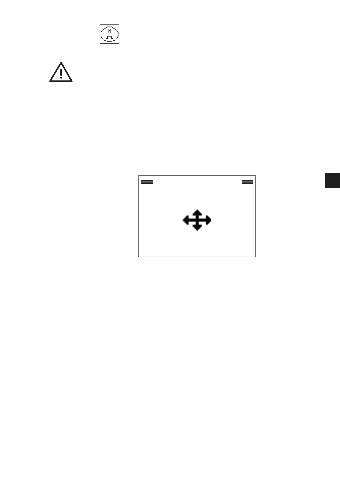
Sewing pattern size/ s ewing pattern offset sub menu
Switch to this sub menu to set the sewing patter n size of the sewing
pattern offset. The current sewing patter n size is shown in the X and Y
direction.
1
Sewing pattern width
Setting the sewing patter n width
Enter: 0.1 … 40 mm
Sewing pattern length
Setting the sewing patter n length
Enter: 0.1 … 20 mm
Sewing pattern offset in X direction
To set the sewing pattern offset in the X direction
Enter: -20.0 … +20.0 mm
Sewing pattern offset in Y direction
To set the sewing pattern offset in the Y direction
Enter: -10.0 … +10.0 mm
25
Page 28
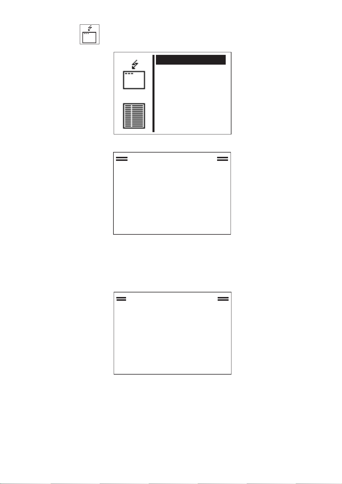
Sub-menu
: Aus
: Ein
There is a sub menu behind this symbol.
Number of stitches
With standard sewing patterns t his menu line displays the overstitch
distribution with the standard sewing patterns and the total number of
stitches with the free contours (cannot be changed).
Selecting the line by pressing “OK” takes you to the “Special
functions” sub menu.
Daily unit counter or capacity counter sub menu.
Selecting the line by pressing “OK” takes you to the “Daily piece
counter or the capacity counter” sub menu.
Resetting the daily piece counter
–
Press “ñ”or“ò ”toswitchtothe menuitem.
–
Hold “OK” down for 3 seconds until the number displayed goes
back to 0.
The daily piece counter can also be reset in this w ay if the capacity
level is displayed. However, the value does not go back to 0.
or
Capacity counter
Selecting the line by pressing “OK” takes you to the “Daily piece
counter or the capacity counter” sub menu.
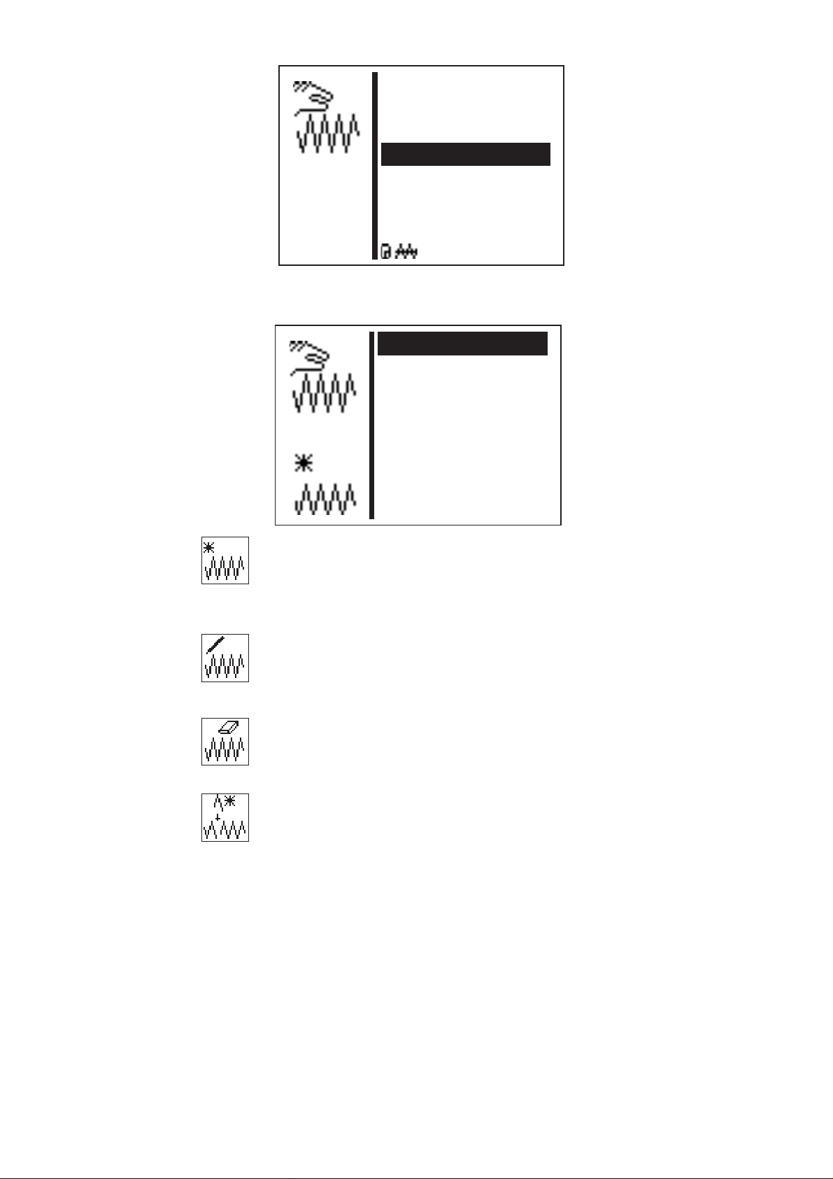
Special function and soft start status sub menu
26
Thread winding mode
The hook thread winder can be operated separately.
The sewing motor can be started with the pedal or manual switch
regardless of the step motors if ON is set.
Enter: ON / OFF
Page 29

Winding hook thread bobbins:
With the pedal
–
Move the pedal forwards (position 2).
The sewing motor starts.
–
Move the pedal back.
The sewing motor stops.
Using the control panel
–
Press “F”.
The sewing motor starts.
–
Press “ESC”.
The sewing motor stops.
With manual switch (optional)
–
Press switch 2.
The sewing motor starts.
–
Press switch 1.
The sewing motor stops.
1
Soft start
The soft start can be switched on or off with this parameter.
Enter: ON / OFF
Laser marking lights sub menu (optional)
This menu item is only displayed if the laser light option
is switched on in the Fittings menu (see Section).
Laser lights 1 ...3
Switching the laser marking lights 1 - 3 on or off
Enter: ON / OFF
27
Page 30

Daily piece counter or capacity counter sub menu.
P
Alternative display of daily piece counter or capacity counter.
Both counters work in parallel.
The counter that is to be displayed in the main menu can be selected.
The daily piece counter counts the number of sewing patter ns
·
sewn
Display: 0 … 65000
The hook thread counter works backwards.
·
When the value 0 is reached and a sewing procedure starts a
message appears.
Display: 9999 … 0
–
“Press ESC .
This switches back to the main menu.
If the daily piece counter is set the following appears:
Daily piece counter display in sewing mode
Enter: Select by pressing OK.
Capacity counter display in sewing mode
Enter: Select by pressing OK.
Capacity counter on/off
Enter: ON / OFF
Initial capacity counter value
Enter: 0 … 9999
28
Page 31

8.6.2 Programming mode
:51
:1
: 2000
:35
: 3.4/ 3.4
: 0.0/ 0.0
: 0/ 0.5
: 0/ 0.5
The parameters for programming sewing patterns are arranged under
this menu item.
The shape, length, width and speed etc. of the sewing patter n are
entered using the parameters.
–
Switch the main switch on.
The control unit is initialized.
The main menu appears.
–
When the main menu appears press P.
The display switches to the programming mode display.
–
Select the required parameters by pressing “ñ”or“ò”.
The symbol for the selected parameters is shown inversely.
–
Change the selected parameters as described in Section 8.3.
1
Sewing pattern number
The sewing pattern number that is to be created or changed is
selected using this parameter.
When creating a new program an asterisk (*) is displayed before the
number.
Enter: 51 … 90
–
Select the required sewing pattern program by pressing “ñ”or
“ò”.
–
“Press OK.
The program is selected.
Basic sewing pattern
A default sewing pattern can be selected with this parameter. The
new sewing pattern is to be created based on this.
Enter: 1 … 50 or
91 … 99 if available.
Sewing speed
The required sewing speed is set with this parameter.
Enter: 0...2700 rpm
29
Page 32

Thread tension sub menu
Switch to this sub menu to set the thread tension.
The values displayed correspond to the thread tension in area 2
(overstitches).
Securing stitch sub menu
Switch to this sub menu to change the parameters for the securing
stitches. The current values are displayed (number/ distance between
the stitches).
Interloop stitch sub menu
Switch to this sub menu to change the parameters for the interloop
stitches. The current values are displayed (number/ distance between
the stitches).
Distance betw een button holes sub menu
Switch to this sub menu to set the distance between button holes in the
X and Y direction seePage25).
Display: current distance between button holes X/Y
Sewing pattern offset sub menu
Switch to this s ub menu to move the sewing pattern in the X and Y
direction (see Page 25).
Display: current X offset/ Y offset
Stitch distribution/ number of stitches
Displays the overstitch distribution (with standard sewing patterns) or
total number of stitches (with free contours).
Soft start
The soft start can be switched on or off with this parameter.
Enter: ON / OFF
Laser marking lights sub menu (optional)
This menu item is only displayed if the laser light option is switched on
in the Fittings menu.
Laser lights 1 ...3
Switching the laser marking lights 1 - 3 on or off
Enter: ON / OFF
30
Page 33

Thread tension sub menu
:35
:35
:35
Ó :0
: 0.5
Thread tension for securing stitches
The thread tension for securing stitches is set with this menu item.
This menu item is only displayed if 0 is not set for the number of
securing stitches.
Overstitch thread tension
The thread tension for overstitches is set with this menu item.
Interlooped stitch thread tension
The thread tension for interlooped stitches is set with this menu item.
This menu item is only displayed if 0 is not set for the number of
interlooped stitches.
Thread tension area 2 … 4
With sewing pattern programs with a free seam contour as the basic
sewing pattern these menu items are displayed if they have been
programmed as stitch operations in the free seam contour.
Enter: 0 … 100 0 = lowest thread tension
100 = highest thread tension
Securing stitch sub menu
The number and distance between the securing stitches at the start of
the seam can be set. The distance between the securing stitches
remains at the set amount even if the sewing patter n is scaled.
1
31
Page 34

Number of securing stitches
Ó :0
: 0.5
The number of securing stitches at the start of the seam can be set
here.
Enter: 0 … 3 (0 = no securing stitches)
Distance between securing stitches
The distance between the securing stitches in the X and Y direction
can be set here.
Enter: 0…1.0mm
When sewing a sewing pattern without securing stitches it is possible
that, because of a very small number of stitches, the specified speed
will not be reached particularly with sewing patter ns with interim
cutting. If necessary the soft start function can be switched of or the
soft start speed adjusted to achieve an increase in speed.
Interloop stitch sub menu
The number and distance between the interloop stitches at the start of
the seam can be set. The distance between the interloop stitches
remains at the set amount even if the sewing patter n is scaled.
Number of interloop stitches
The number of interloop stitches at the s tart of the seam can be set
here.
Enter: 0 … 3 (0 = no interloop stitches)
Distance between interloop stitches
The distance between interloop stitches at the end of the seam can be
set here.
Enter: 0…1.0mm
When sewing a sewing pattern without interloop stitches it is possible
that, because of a very small number of stitches, the specified speed
will not be reached particularly with sewing patter ns with interim
cutting. If necessary the soft start function can be switched of or the
soft start speed adjusted to achieve an increase in speed.
32
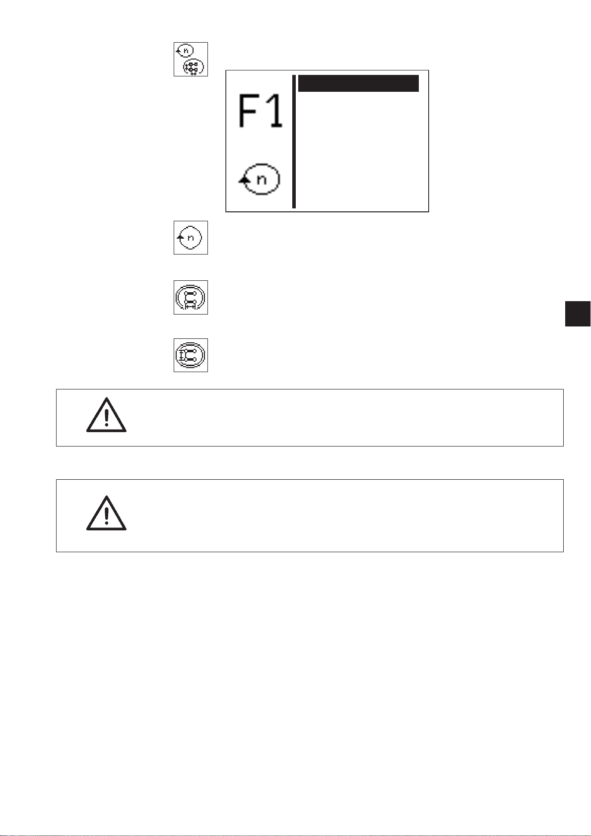
Page 35
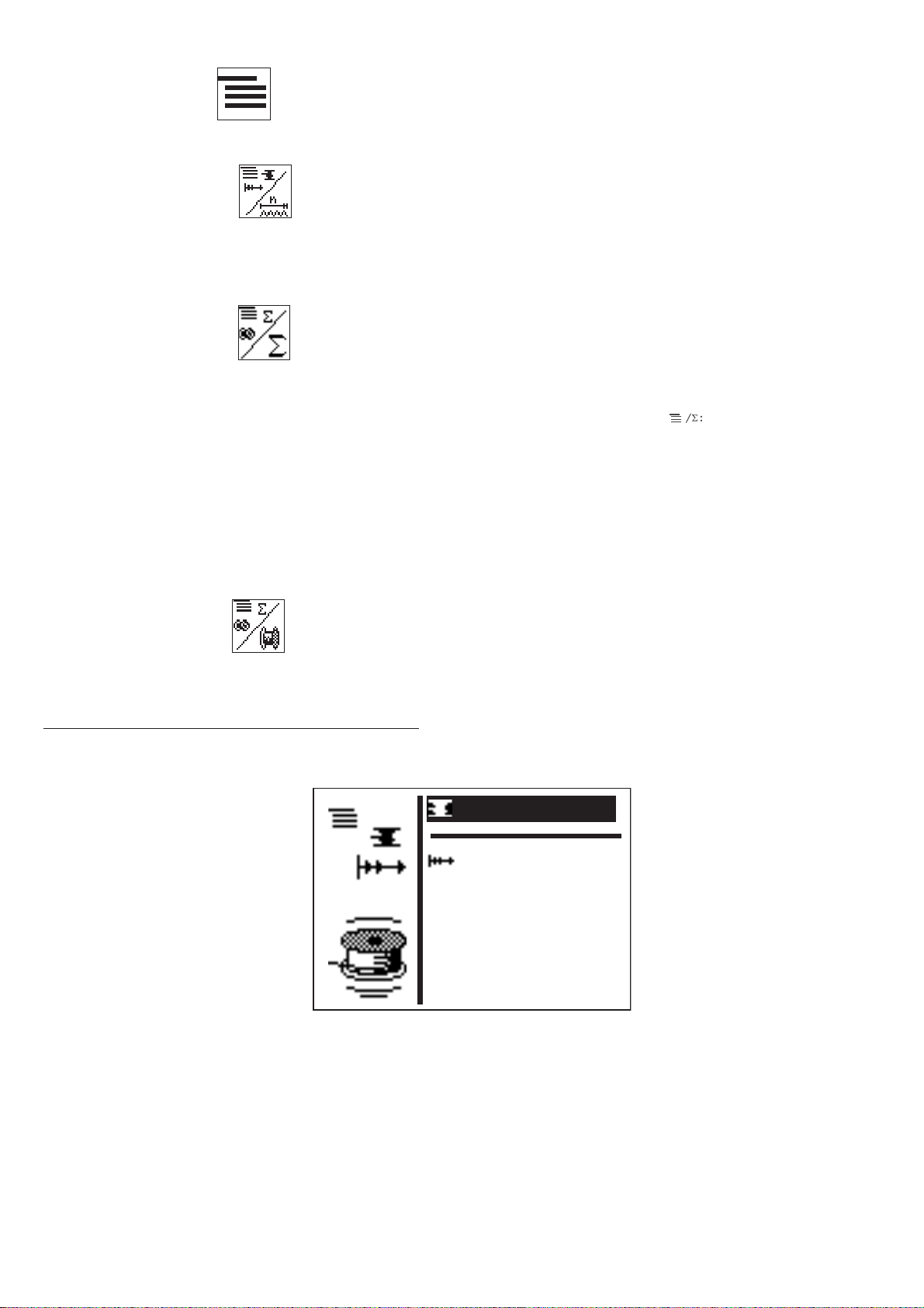
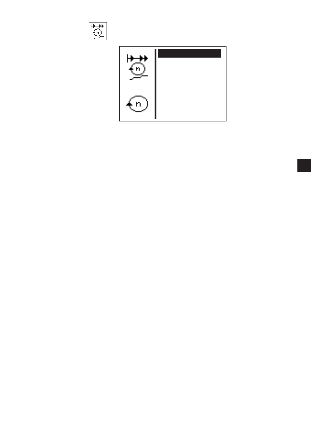
8.6.3 Copying function for sewing pattern programs
Any number of sewing patterns can be copied at programming level:
–
Press P to switch from the main screen to the sewing pattern
programming mode.
–
Press OK to select the sewing pattern program to be copied with
the “ñ”and“ò” cursor keys. Then confirm by pressing OK.
–
Press P to start the copying process. A dialogue box appears to
confirm:
1
(Example)
–
Press “ð” (Yes) to start the copying procedure. A copy of the
selected sewing pattern is attached to the existing ones and
selected as the current one.
–
Press “ï” (No) to cancel the copying procedure.
33
Page 36

8.6.4 Sewing pattern sequence (sequences)
: Aus
:1
01-02-51-91
: 2000
:35
: 3.4/ 3.4
/ :6-6
/Ó: 0
8.6.4.1 Switching sewing pattern sequence operation on and off
Switching from sewing pattern mode to sewing patter n sequence
mode
–
With the main menu displayed press S to go to the sequence
programming mode.
–
Press OK to start editing the sequence numbers.
–
Press ñ to select any sequence (1-25)
–
Press OK to confirm the selection.
The sewing pattern sequence mode is switched on.
–
Press ESC or “ï”.
The main menu for the sewing patter n sequence mode appears.
34
The sequence number and sequence menu items in the main menu are
described at the end of this section.
Page 37

Switching from sewing pattern sequence mode to sewing pattern
:1
01-02-51-91
: 2000
:35
: 3.4/ 3.4
/ :6-6
/Ó: 0
:1
: 2000
:35
: 3.4/ 3.4
/ :6-6
/Ó: 0
mode
–
With the main menu displayed press S to go to the sequence
programming mode.
–
Press OK to start editing the sequence numbers.
–
Press “ò” to select sequence number 0.
–
Press OK to confirm the selection.
The sewing pattern sequence mode is switched off.
–
Press ESC or “ï”.
The main menu for the sewing patter n mode appears.
1
35
Page 38

Menu items in the main menu in sewing pattern mode
01-02-51-91-
...51-91-01-02
...02-51-91-01-...
01-02-51-91
0102 51 91
01-02-51-91
01 02 51 91
01 02 51 91
Sequence
Selecting the sewing patter n sequence.
Enter: 1 (2 - 25, if available)
Sequence
Displaying the sequence.
The current sewing pattern number is indicated with a bar
(underlined).
The display scrolls if there are more than five numbers.
–
More sewing patterns to the right:
More sewing patterns to the left:
More sewing patterns to the left and right:
Automatic mode
After sewing a sewing pattern the control unit automatically switches
to the next sewing patter n.
After sewing the last sewing pattern the control unit switches back to
the first sewing pattern in the sequence.
The current sewing pattern is indicated by a bar under the number.
The design of the s elected sewing patter n is displayed in the left half
of the display.
Manual operation
The control unit does not switch automatically between sewing
patterns.
–
Press “ï”or“ð” to display the next sewing pattern.
The design of the s elected sewing patter n is displayed in the left
half of the display.
Switching between automatic and manual mode
–
Press “ñ”or“ò ” to s elect the second menu line (sequences).
–
Press OK.
–
Press “ñ”or“ò ” to s elect the operating mode.
An arrow will be displayed between the sewing patter ns in
automatic mode.
36
Automatic mode
Manual mode
Page 39

8.6.4.2 Sequence programming mode
: Aus
This menu item combines the individual sewing patterns for the
sewing pattern sequences that can be called up.
There is a total of 25 independent sewing pattern sequences
available. Each sewing pattern sequence can be made up of 20
sewing patterns in any order.
The sewing pattern sequence mode can also be switched on in this
menu.
–
Switch the main switch on.
The control unit is initialized.
The main menu appears.
–
When the main menu appears press S.
The display switches to the sequence programming mode.
–
Select the required menu item by pressing “ñ”or“ò”.
The menu line shown inversely.
–
“Press ESC or ï.
This switches back to the main menu.
Sequence number/ sewing patter n sequence mode
Selecting the sequence to be created or changed.
When creating a new program an asterisk (*) will be displayed before
the number.
Enter: 0 … 25
–
Select the required sequence number by pressing “ñ”or“ò”.
Should sewing pattern sequence mode be switched off select
sequence number 0.
The sequence number is shown inversely.
–
“Press OK.
The program is selected.
Sewing pattern number (1 .. 20)
This menu item is used to select the sewing patter n number that is to
be included in the current sequence.
Enter: 1 … 51 (52 - 99 if available)
1
37
Page 40
8.6.5 Technician mode
The following menus are included in technician mode:
Machine configuration
Machine-specific settings are configured in this menu.
User configurations
Operation-specific settings are configured in this menu.
Service functions
Service functions enable a rapid check of all hardware components.
Free contours
Up to nine freely defined seam contours can be created and sewn with
the button sewer 531. The co-ordinates are entered directly on the
control panel.
Memory dongle
Data can be transferred from the machine to the dongle or loaded
from there onto the machine using the memory dongle support.
Cycle time
Displays the cycle time of the last sewn sewing patter n.
(Time from start to end of sewing).
38
Page 41

Calling up technician mode
0****
Code
Maschine c
Benutzer
Service
Freie Konturen
Memory-Dongle
:----
–
Switch the main switch on.
The control unit is initialized.
The main menu appears.
–
When the main menu appears press F.
The display switches to the code query menu.
–
Enter code number “25483”(Code1).
The display switches to technician mode when the right code
number has been entered.
–
Press “OK” to confirm.
The following menu appears:
1
–
Select the required sub menu by pressing “?”or“?”.
–
Press “OK” to switch to the selected sub menu.
39
Page 42
8.6.5.1 Machine configuration
Parameter c
Softstart
Einrichtung
Zeiten
Ó
:262
Parameters
Various machine parameters can be set using this sub menu.
Soft start
The speeds for the soft start ramp can be set in this sub menu.
Equipment
The parameters for the sewing equipment and optional units can be
set in this sub menu.
Times
The different t imes can be set in t his sub menu.
Machine cycles
The total number of sewn cycles is displayed.
40
Page 43

Machine parameters
Absch.dz.: 210
Max.Dz.: 2500
Stoppos.: -15
Einlegepos.: A
Referenz.: 1
Kl.Fuß-Lüft: A
W.Rückdr.: 0
W.Fsp öf.: 320
–
Select the required parameters by pressing “?”or“?”.
The symbol for the selected parameters is shown inversely.
–
Start the selected parameters by pressing OK or switch to the sub
menu.
Cut off speed
Enter the sewing motor speed in the last three stitches.
Enter: 200 … 300 [rpm]
Maximum sewing speed
Enter the maximum sewing speed that can be set
Enter: 200 … 2700 [rpm]
Stop position
The positioning of the s ewing motor or needle bar can be changed
using the stop position.
Enter: 0 = Thread lever is at the upper dead center
(needle bar is lower)
-15 = Thread lever is 15° off the upper dead center
(Needle bar is higher)
Feed position
Selecting the feed position for the material.
Enter: A = Seam starting point
B = Machine zero point
1
Note
The following advantages or disadvantages arise depending on the
feed position:
Feed point A = low cycle time
Feed point B = easier feed for larger
sewing patterns, longer c ycle time.
41
Page 44
Referencing
The behavior for referencing the step motors after a sewing procedure
can be configured using this menu item.
Enter : 0 = no referenc in g
1 = reference each time
2 – 10 = after every 2nd - 10th sewing procedure.
Raising the clamping foot
Setting whether the clamping foot is to be raised after referencing the
step motors.
Enter: A = the clamping foot is raised before referencing.
B = the clamping foot is raised after referencing.
Sewing motor reverse rotation angle
After the end of t he sewing procedure it is possible to rotate the
sewing motor backwards so that the needle can reach a higher
position. Before the next sewing procedure the needle position is
moved once more to the sewing motor stop position. The angle that
the sewing motor is to be back rotated can be set.
Enter: 0 … 70° ( 0° = back rotation switched off)
(70° = highest needle position)
Opening the thread tension angle
Setting the angle to open the thread tension in the last stitch.
Enter: 200° … 355°
The thread tension is opened before reaching the thread cut off
position. Thus only the mechanical pre-tensioning works in the cutting
procedure.
All angles are given from the sewing motor reference position.
42
Page 45
Soft start
1. Stich: 400
2. Stich: 400
3. Stich: 1000
4. Stich: 2700
5. Stich: 2700
The speed parameters for the soft start can be set in this sub menu.
Speed of 1st stitch
Enterthespeedforthefirststitch.
Enter: 400...900 [rpm]
Speed of 2nd stitch
Enter the speed for the second stitch.
Enter: 400 … 2700 [rpm]
1
Speed of 3rd stitch
Enter the speed for the third stitch.
Enter: 400 … 2700 [rpm]
Speed of 4th stitch
Enter the speed for the fourth stitch.
Enter: 400 … 2700 [rpm]
Speed of 5th stitch
Enter the speed for the fifth stitch.
Enter: 400 … 2700 [rpm]
43
Page 46
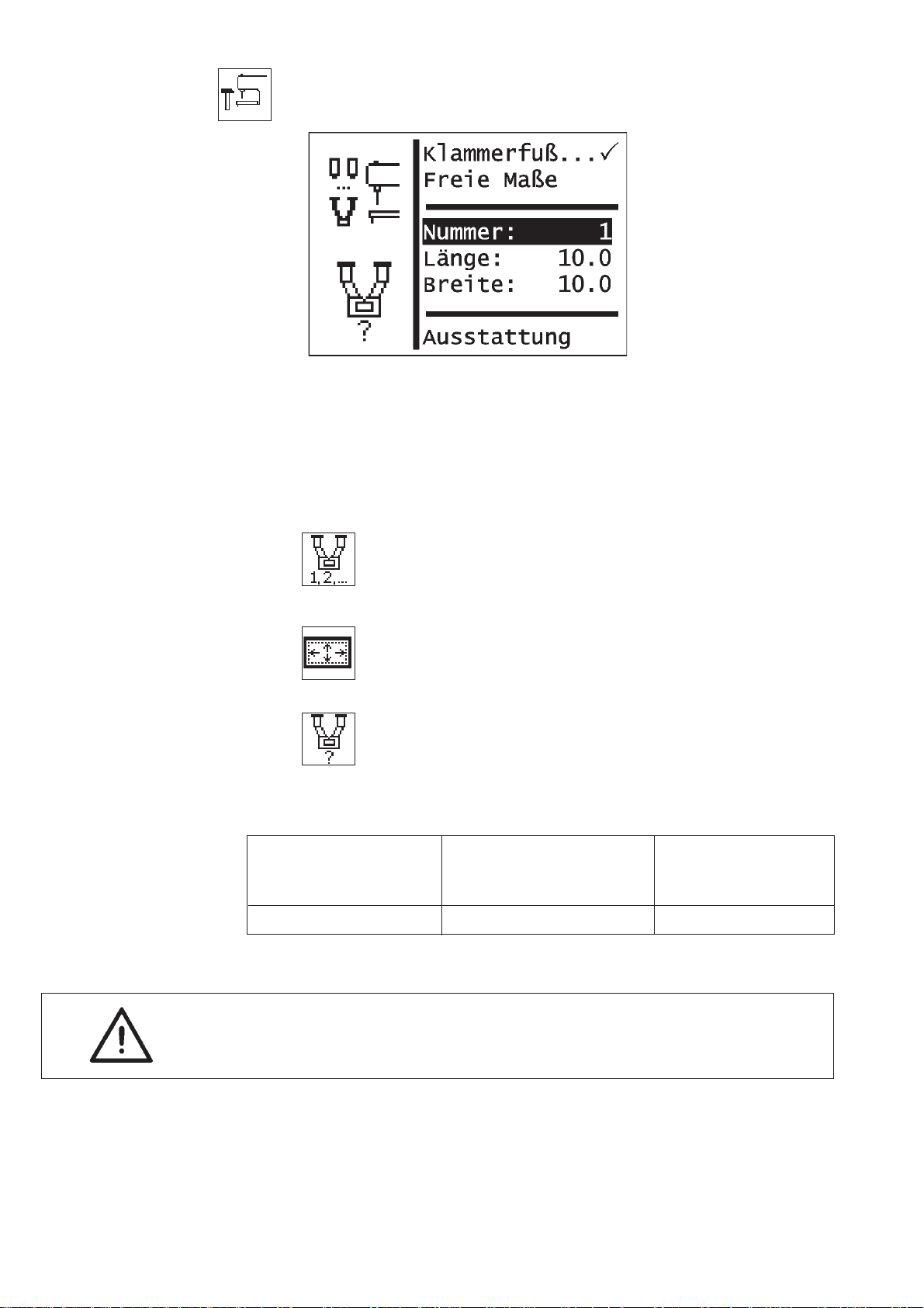
Equipment
The parameters for the sewing equipment can be set in this sub menu.
Note
Entering the clamping foot number automatically checks whether the
sewing pattern currently to be sewn is in the material support plate
opening.
If there are no specified clamping feet free dimensions can also be
defined.
Clamping foot
Selecting a fixed clamping foot as a device.
Enter: Alternative:
Free dimensions
Selecting a clamping foot with free sewing field
dimensions.
Enter: Alternative:
Number
Selecting a DA clamping foot number.
Enter: 1
Clamping foot number Material support plate Description
opening
dimensions X x Y (mm)
1 10x10 buttonclamps
For technical reasons and to provide a safety margin t he sewing
field is smaller than the material support plate opening.
44
Page 47

Length
Entering a freely selectable sewing field length.
Entry only possible if “free clamping measurement”
has been selected. Otherwise the length/ width of the
selected clamps are displayed (cannot be changed).
Enter: 0.5 … 20.0
Width
Entering a freely selectable sewing field width.
Entry only possible if “free clamping measurement”
has been selected. Otherwise the length/ width of the
selected clamps are displayed (cannot be changed).
Enter: 0.5 … 40.0
Equipment
Optional units can be
activated using this sub menu.
1
45
Page 48

Fittings sub menu
Handtast.: Aus
El.Fw.: Ein
Laserl.: Aus
Belegung Eing.
Belegung Ausg.
Manual switch
Activating the optional manual switch. If this option has been selected
a menu item to select the operating mode appears in the “User
configuration” menu.
Enter: ON / OFF
Electrical thread wiper
Switching the electrical thread wiper on/off.
Enter: ON/OFF
Laser lights
Activating the 3 optional laser lights.
Enter: ON / OFF
Assigning the inputs
This menu item gives an overview of the assignment of the inputs with
(optional) units.
Assigning the 24V outputs
This menu item gives an overview of the assignment of the 24v
outputs with (optional) units.
46
Page 49

Times sub menu
t1: 100
t2: 120
t3: 50
t4: 70
t5: 15
Waiting time between pedal position 1 (lower clamping foot) and
start of sewing (t1).
Time only relevant with rapid start using the pedal or the hand switch
(optional).
Enter: 50 ...300 ms
Default value: 150 ms
Switch on time for t hread wiper magnet (t2)
This menu item is only displayed if the electrical thread wiper option is
switched on in the Fittings menu.
Enter: 30 ...100 ms
Default value: 40 ms
1
Time when thread wiper magnet off - clamping foot magnet on (t3)
Waiting time between the thread wiper magnets being switched off
and the clamping foot magnets being switched on.
This menu item is only displayed if the electrical thread wiper option is
switched on in the Fittings menu.
Enter: 0 ...300 ms
Default value: 50 ms
Waiting time between clamping foot magnet coming on and the
refere n c e run (t4 ) .
Waiting time between the clamping foot magnets being switched on
and the step motors being referenced.
Enter: 0 ...300 ms
Default value: 70 ms
Time for activating energy saving mode (t5)
Waiting time between any operating component being operated
(control panel, pedal, manual switch) until energy saving mode is
activated.
Enter: 0 … 60 min 0 = energy saving mode
switched off
47
Page 50
8.6.5.2 User configuration
Sprache 0
Handtaster: A
Par.sperr: Aus
Nähm.sperren
Sequ.sperren
Operation-specific settings are configured in this menu.
–
Select the required parameters/ sub menu by pressing “?”or“?”.
The selected parameters/sub menu are shown inversely.
–
Start the selected parameters by pressing OK or switch to the sub
menu.
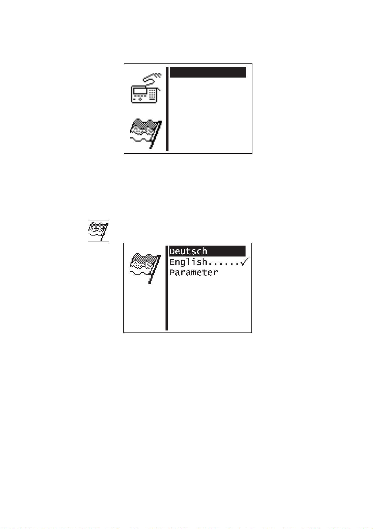
Language
The language can be selected in this sub menu.
48
German
Selects German for the technician level.
English
Selects English for the technician level.
Parameters
Selects the numbering of the menu items for
technician level.
Page 51

Manual switch operating mode (optional)
Selecting the manual switch mode.
This menu item is only available if the “manual s witch” option is
activated in the Fittings menu.
Enter: A = Rapid start
B=Normal
In the “NORMAL” manual switch mode the switches have the
following functions:
Switch 1:Raising and lowering the clamping foot.
Stopping the sewing procedure.
Cancelling the sewing procedure when it has been stopped.
Switch 2:Start sewing when the clamping foot is lowered.
Stopping the sewing procedure.
Continuing the sewing procedure when it has been stopped.
In the “RAPID START” manual switch mode the switches have the
following functions:
Switch 1:Raising and lowering the clamping foot.
Stopping the sewing procedure.
Cancelling the sewing procedure when it has been stopped.
Switch 2:Start sewing.
If the clamping foot is not lowered it is lowered.
Stopping the sewing procedure.
Continuing the sewing procedure when it has been stopped.
1
Parameter blocking
Switching the ability of parameters to be changed on or off in sewing
and programming modes.
Enter: ON / OFF
Note
If the parameter block is switched on no parameter changes are
possible any more in sewing and programming modes.
49
Page 52

Blocking sewing patterns
Alle sperren 0
Alle freigeben
2: Ein
3: Ein
4: Ein
5: Ein
6: Ein
7: Ein
Individual sewing patterns can be released for selection or blocked in
this sub menu.
The following restrictions normally apply:
1. Sewing pattern mode
The sewing pattern currently selected in sewing mode cannot be
·
blocked.
Blocked sewing patterns cannot be selected from the selection list
·
in sewing mode.
Blocked sewing patterns are indicated by “#”.
2. Sewing pattern sequence mode
A blocked sewing pattern can be selected in a sequence. At the
·
start of the sewing sequence (when the clamping foot is lowered,
an error message appears, however. The sewing sequence cannot
be started.
The last selected sewing pattern in sewing mode cannot be
·
blocked.
Block all
All sewing patterns are blocked with the aforementioned restrictions.
The status of the s ewing pattern numbers displayed switches to
“OFF”.
Activate all
All sewing patterns are activated.
The status of the s ewing pattern numbers displayed switches to
“ON”.
Blocking/ activating individual sewing patter ns
Enter: ON / OFF
50
Page 53

Blocking sequences
Alle sperren 0
Alle freigeben
2: Ein
3: Ein
Individual sequences can be released for selection or blocked in this
sub menu.
The following restrictions normally apply:
1. Sewing pattern mode:
The last selected sequence in sequence mode cannot be blocked.
·
2. Sewing pattern sequence mode:
1
The sequence currently selected in sewing mode cannot be
·
blocked.
Blocked sequences cannot be selected from the selection list in
·
sewing mode.
Blocked sequences are indicated by “#”.
Block all
All sequences are blocked with the aforementioned restrictions.
The status of the sequence numbers displayed switches to “OFF”.
Activate all
All sequences are activated.
The status of the sequence numbers displayed switches to “ON”.
Blocking/ activating individual sequences
Enter: ON / OFF
51
Page 54

8.6.5.3 Service functions
Service functions enable a rapid check of all hardware components.
Note
The service menu can be reached directly when switching the
machine on (see Section 8.2.1).
Multi-test
All hardware components can be checked in the Multi-test menu.
180° disc
This menu item makes a function available to set the referencing of
the sewing motor (180° disc) correctly (see Service instructions).
Events
Initialization
Using this menu the events memory and the permanent data can be
reset to factory settings.
52
Page 55

Multi-test
Ausgangstest e
PWM-Ausg.test
Eingangstest
Auto-Eing-Test
Nähmotortest
Schrittm.test
RAM-Test
EEPROM-Test
Selecting the Multi-test sub menu
Caution, danger of injury!
Do not put your hands into the running machine during the function
check of the output components.
1
Risk of breaking!
When testing individual output components first of all check whether
collisions may occur when the machine moves.
53
Page 56

Output test
Ausgang Y1: -
Ausgangstest
The function of the output components is checked with this test
function.
–
Start the test function by pressing OK.
–
Select the required output component by pressing “?”or“?”.
–
Switch the selected output component on or off by pressing OK.
–
To exit the test function press ESC.
Caution, danger of injury!
Do not put your hands into the running machine during the function
check of the output components.
Output Function
component
Y1 Thread wiper magnet
Y4 Thread tension magnet
Y21 Laser marking light 1, if option is activated
Y22 Laser marking light 2, if option is activated
Y23 Laser marking light 3, if option is activated
Cf. also paragraph 8.7 Distributor circuit board
54
Page 57

PWM output test
Ausgang Y31: 0
PWM-Ausgangstest
The function of the magnets is checked with this test function.
–
Start the test function by pressing OK.
–
Select the required output component by pressing “?”or“?”.
–
Switch the selected output component on or off by pressing OK.
–
The current that is flowing through the clamping foot magnet is
displayed.
–
To exit the test function press ESC.
1
Caution, danger of injury!
Do not put your hands into the running machine during the function
check of the output components.
Output component Function
Y31 Clamping foot magnet
Cf. also paragraph 8.7 Distributor circuit board
55
Page 58

Input test
Eingang S14: -
Eingangstest
The input components to be tested are selected with this test
function.
CAUTION!
The input components are set carefully at the factor.
Configuring and correcting them must only be done by trained service
personnel.
–
Start the test function by pressing OK.
–
Select the required input component by pressing “? ”or“?”.
The switching status of the input component is displayed.
–
Input component Function
S1 Manual switch 1, if the option is activated
S2 Manual switch 2, if the option is activated
S14 Pedal A
S15 Pedal B
S16. Pedal C
S17 Pedal D
N ref. Sewing motor reference switch
X ref. X refe re nc e switch
Y ref. Y refere n ce switch
To exit the test function press ESC.
The Multi-test menu appears.
56
The current assignment of the inputs is specified in the Fittings menu
in the “Assignment of inputs” sub menu.
Cf. also paragraph 8.7 Distributor circuit board
Page 59

Auto input test
Eingang S14: -
Auto-Eing-Test
The function of the input components is checked with this test
function.
–
Start the test function by pressing OK.
–
Operate the required input component.
The switching status and number of the input component operated
are displayed.
–
To exit the test function press ESC.
The Multi-test menu appears.
To assign input components see the Input test table.
1
57
Page 60

Sewing motor test
Nähmotortest
The sewing motor can be checked with this test function.
–
Start the test function by pressing OK.
–
Startthemotorbypressingñ.
–
Change the speed by pressing “?”or“?”.
The speed is displayed.
–
Press ESC.
The test finishes and the motor stops.
The sewing motor control unit performs a reference run and the
clamping foot is raised.
The Multi-test menu appears on the display.
58
Page 61
Step motor test
0
0+
+
Schrittmotortest
The step motors and the associated reference switches can be
checked with this test function.
CAUTION Risk of breaking!
Move the needle upwards with the hand wheel before the test.
–
Start the test function by pressing OK.
–
Check the step motor for transverse movement (X axis).
Move the step motor by pressing “ï”or“ð”.
The number of steps moved is shown by the arrow on the left.
The status of the reference switch is modified by the reference
setting.
–
Check the step motor for lengthwise movement (Y axis).
Move the step motor by pressing “ñ”or“ò”.
The number of steps traveled is shown above the arrow.
The status of the reference switch is modified by the reference
setting.
1
–
Press ESC.
The test finishes.
The Multi-test menu appears on the display.
59
Page 62

RAM test
The memory (SRAM and program data memory) is checked with this
test function.
–
Start the test function by pressing OK.
The test results are displayed.
Display Explanation
SRAM OK The memory is working properly
SRAM ERROR Error in the memory
NV-RAM OK Program data memory is OK
NV-RAM ERROR Error in program data memory
–
Press ESC.
The test finishes.
The Multi-test menu appears on the display.
60
Page 63

EEPROM test
ROM-Gr.: 675k
Klasse: 531
Version: A01.0
Datum: 30.09.09
Checks.: 0x1234 Ok
EEPROM-Test
This test function checks the microprocessor’s programmable read
only memory (ROM).
–
Start the test function by pressing OK.
The display shows the following rest results:
-ROMsize
- Machine class
- Software version
- Software date
- checksum and status
1
Note:
The details change depending on the software version.
–
Press ESC.
The test finishes.
The Multi-test menu appears on the display.
61
Page 64
Events
Ereignissp. .
Letzte Ereign.
E4304 3 x
E8254 1 x
Ereignisspeicher
1 E4304 Z 1154889
S 263
2 E4304 Z 1152558
S 263
3 E8254 Z 1150034
S 263
Letzte Ereignisse
In the event of a malfunction the menu can give important information
on the cause of the malfunction.
Event memory
62
(Example)
All events that have occurred are displayed in this menu item.
–
Exit the menu item by pressing ESC.
–
Display again by pressing ò .
Latest events
(Example)
The latest events that have occurred are displayed in this menu item.
Z = milliseconds after switching the machine on
S = Machine unit c ounter
E = Event/ error number
–
Exit the menu item by pressing ESC.
–
Display again by pressing ? .
Page 65

Initializing (Init)
Ereignissp. e
Progr./Sequ.
Masch./Benutz.
Fr. Konturen
Maschine kpl.
Selecting the sub menu to initialize the event memory and permanent
data.
Event memory
The event memory can be reset using this menu item.
Sewing pattern programs (variations) and sequences
Sewing pattern programs and sequences can be deleted using this
menu item.
Machine parameters
Machine parameters, soft start s peeds, times, user configuration,
hook thread counter data and options can be reset to factory settings
using this menu item.
Free seam contours
All free seam contours can be reset (deleted) using this menu item.
Note
By resetting sewing pattern programs and sequences are also deleted
and the numbers of subsequent programs and sequences modified.
Whole machine
All permanent data can be reset using this menu item. After resetting
the machine is restarted automatically.
1
Note
After the machine has been restarted the clamp number and fittings
must be selected again (see installation instructions Section 9).
63
Page 66
8.6.5.4 Free contours
Maschine
Benutzer
Service
Freie Konturen
Memory-Dongle
:----
Erstellen n
Ändern: 0
Löschen: 0
Kopieren: 0
Anz.v.St.:3000
Anz.v.Kont.: 9
Up to nine freely defined seam contours can be created and sewn with
the button sewer 531. The co-ordinates of the seam contour are
entered on the control panel.
Create
A new seam contour can be created with this menu item.
Note
The seam contour number is allocated automatically.
Modify
After selecting the seam contour to be modified you go to the sub
menu for changing the seam contour.
Delete
A selected seam contour can be deleted with this menu item.
Copy
Any basic sewing patter n number of free seam contour can be copied
and modified. After selecting the sewing patter n number you go to the
“Change seam contour” sub menu.
–
Select the required standard sewing pattern by pressing “ñ”or
“ò”.
–
Select the standard sewing patter n by pressing OK .
Note
The seam contour number is allocated automatically.
64
Number of available stitches:
The number of stitches still available is displayed (max. 3000).
Number of available contours:
The number of contours still available is displayed (max. 9).
Page 67

Determining contour co-ordinates
When creating a seam contour each individual stitch with details of
the position on the co-ordinate cross (S and Y axis) must be entered
into the control unit. The individual co-ordinate points must therefore
be determined in advance.
The co-ordinate points can be determined using millimeter paper.
1
Maximum sewing area stitch to be determined
(grey field)
seam contour recorded
Machine zero point
Co-ord i na t e cross w it h
XandYaxis
Note
The seam contour should be created so that the machine zero point is
in the middle of the contour as far as possible.
–
Draw the maximum sewing field size on the millimeter paper (X =
max. 40 mm, Y = max. 20 mm).
–
Put the co-ordinate cross in the middle of the sewing area.
–
Plot the seam contour.
–
Determine the X and Y co-ordinates for each required stitch.
–
Enter the X and Y co-ordinates into the control unit (see next
page).
65
Page 68

Creating the contour
X1: 0.0
Y1: 0.0
X2: 0.0
Y2: 0.0
X3: 0.0
Y3: 0.0
Stich anfügen
Parameter
The X and Y co-ordinates for each individual stitch are entered in this
menu.
Note:
To enter stitch operations (e.g. interim cutting) first of all complete the
contour (enter co-ordinates) and then insert into the C hange contour
menu by editing the stitch operation.
X1
Entering the X co-ordinates for stitch 1
Enter: -20.0 … +20.0
Y1
Entering the Y co-ordinates for stitch 1
Enter: -10.0 ...+10.0
66
Note:
The value X1 can be changed as shown in Section 8.3.1.
After confirming the value of X1 by pressing OK select menu item Y1
by pressing “ò”.
The values for Y1, X2, Y2, X3 and Y3 can be changed as described for
value X1.
After confirming the entry of Y3 by pressing OK select “Add stitch”
by pressing ò.
After selecting this line by pressing OK the next co-ordinates Xn1 +1
and Yn+1 are specified in the top two menu lines (here: X4 and Y4).
The selection bar switches automatically to the line Xn+1 (here: X4).
The values Xn+1 and Yn+1 can be changed if necessary as described
above. This procedure can be repeated until all the stitch co-ordinates
have been entered.
Adding a stitch
Function to add a stitch.
The co-ordinates for the first three stitches (here: X1/Y1, X2/Y2 and
X3/Y3) are moved upwards and Xn+1/Yn+1 (here: X4/Y4) appears on
the display.
Page 69
Parameter sub menu
Std.dz.: 1500
Abst. X: 0.0
Abst. Y: 0.0
Selecting the sub menu to enter the contour parameters
Default speed:
Default speed
Enter: 100...2700 rpm
Distance X:
Distance from the hole in t he X direction
Enter: 0 ...40.0 mm
1
Distance Y:
Distance from the hole in t he Y direction
Enter: 0...20.0 mm
Default values = exter nal stitches in X and Y direction
Values must be changed depending on the distance between the
button and the hole (refers to correct scaling in the main menu).
If the free seam contour is currently selected in the main display and if
one or both of the X/Y distances have been changed, the value for the
length or width or both must be changed accordingly in the main
menu.
67
Page 70

Change contour
Stichkoord. 0
St.entf.: 0
St.einf.: 0
Stich anfügen
Parameter
Anz.St.: 100
Anz.v.St.:2900
1- 99
100 - 110
Stitch co-ordinates
Selecting the sub menu to change the stitch co-ordinates.
Removing a stitch:
Delete stitch.
Enter: stitch number to be deleted
Inserting a stitch:
Insert stitch.
Enter: Stitch number before which a stitch is to be inserted.
The sub menu to change the stitch co-ordinates appears.
Adding a stitch (at the end)
The sub menu to change the stitch co-ordinates appears.
Parameters
Selecting the sub menu to change the contour parameters
Stitch co-ordinates sub menu
The sub menu appears immediately if the contour to be changed has
99 stitches or fewer.
The following menu appears if the contour to be changed has more
than 99 stitches:
68
–
Select the required stitch area by pressing “?”or“?”.
–
Select the stitch area by pressing OK.
The “Stitch co-ordinates” sub menu appears.
Page 71
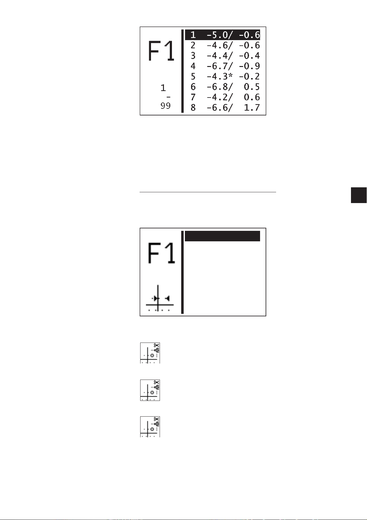
–
X10: 1.70
Y10: 1.70
Op1: Keine Op.
Op2: Keine Op.
Op3: Keine Op.
Select the required stitch by pressing “?”or“?”.
–
Select the stitch by pressing OK.
The sub menu to change a stitch co-ordinate appears.
If a stitch operation is allocated to a stitch this will be marked by an
asterisk (*) instead of a forward slash (/).
Changing the stitch co-ordinates sub menu
This sub menu appears when selecting a stitch co-ordinate from the “Stitch co-ordinates” menu after
inserting or changing a stitch.
Example:
Op 1
Changing the traveling operation of stitch 10.
Enter: see Table on page 70
1
Op 2
Changing the thread tensioning operation of stitch 10.
Enter: see Table on page 70
Op 3
Changing the speed operation of stitch 10.
Enter: see Table on page 70
Note:
The stitch operation entered is performed after the stitch.
69
Page 72

Type of operation Operation Description
Traveling operation
(Op 1)
Thread tension operation
(Op 2)
Intermediate cutting
Thread tension 1
Thread tension 2
Thread tension 3
Thread tension 4
Thread tension 5
Speed 200
Speed 400
Speed 600
Speed 800
Speed 1000
Speed 1200
Intermediate cutting can be programmed
in a contour up to 10 times.
There must be at least 3 stitches
between 2 intermediate cutting
procedures.
Thread tension area 1
Thread tension area 2
Thread tension area 3
Thread tension area 4
Thread tension area 5
Speed reduction to 200 1/min
Speed reduction to 400 1/min
Speed reduction to 600 1/min
Speed reduction to 800 1/min
Speed reduction to 1000 1/min
Speed reduction to 1200 1/min
Speed operation
(Op 3)
Speed 1400
Speed 1600
Speed 1800
Speed 2000
Speed 2200
Speed 2400
Speed 2600
Default speed
If “No operation” is selected the corresponding stitch operation is
switched off.
Speed reduction to 1400 1/min
Speed reduction to 1600 1/min
Speed reduction to 1800 1/min
Speed reduction to 2000 1/min
Speed reduction to 2200 1/min
Speed reduction to 2400 1/min
Speed reduction to 2600 1/min
Set to default speed
70
Page 73

Deleting a contour
Erstellen
Ändern: 0
Löschen: 0
Kopieren: 0
Anz.v.St.:2975
Anz.v.Kont.: 8
–
Select Delete by pressing ñ or ò.
–
“Press OK.
–
Select the required contour number by pressing “? ”or“?”.
–
Confirm the selection by pressing OK.
The contour is deleted.
1
CAUTION!
By deleting a free seam contour the numbering of sewing patter n
programs and/or sequences may change as these may be deleted too.
71
Page 74

Copying a contour
Stichkoord. 0
St.entf.: 0
St.einf.: 0
Stich anfügen
Parameter
Anz.St.: 25
Anz.v.St.:2975
Erstellen
Ändern: 0
Löschen: 0
Kopieren: 0
Anz.v.St.:3000
Anz.v.Kont.: 9
–
Select Copy by pressing ? or ?.
–
„Press OK.
–
Select the required sewing pattern number (1-50,91-99) by
pressing “?”or“? ”.
–
Confirm the selection by pressing OK.
The contour is copied and the “Change contour” menu is
displayed.
The contour is changed by following the “Change contour” section
on Page 68.
72
Page 75

8.6.5.5 Memory dongle
Inhalt 1
Laden
Speichern
Formatieren
Using the functions of this sub menu data from the machine can be
saved on a dongle or data from a dongle can be loaded onto the
machine.
Dongle content
Using this menu item the content of a memory dongle inserted into the
control unit can be displayed.
1
Load
Using this menu item program data (sewing pattern programs and
sequences) and machine parameters as well as free seam contours
can be uploaded from the dongle to the machine.
Save
Using this menu item program data (sewing pattern programs and
sequences) and machine parameters as well as free seam contours
can be saved on a data dongle.
Format
A dongle must be formatted as a data dongle to save data.
The dongle must be inserted into the control unit in the pin connection
marked Dongle (X110).
73
Page 76

Display dongle content
Klasse: 531
U-Klasse: 000
Version: A01
Datum: 300909
P01: 51
P02: 52
P03: 53
Boot dongle
If a boot dongle is inserted information about the machine program is
output.
(Example)
A boot dongle with a machine program for any machine class can be
inserted in order to display the dongle information.
Data dongle
If a data dongle is inserted that has been formatted for machine class
531 the saved sewing patter n programs or free seam contours are
displayed.
Reading out the saved sewing pattern programs
(Example)
Press ð to switch between the saved sewing patter n programs
display and the free seam contours display.
74
Page 77

Reading out the saved free seam contours
Data Dongle 1
Klasse: 511
Inhalt
Fr.Konturen n
Progr./Sequ.
Masch.param.
Maschine kpl.
(Example)
Data from a different machine class dongle
The following display appears if a dongle for a different machine class
is inserted.
1
(Example)
Loading data from the dongle to the machine
Using this menu item program data (sewing pattern programs and
sequences) and machine parameters or all free seam contours can be
loaded from the dongle to the machine.
(Example)
75
Page 78

Content
Using this menu item the content of a memory dongle inserted into the
control unit can be displayed.
Before loading the following four data areas a window appears for
each of them to confirm the selection.
–
Press
ï (No) to cancel the procedure or
ð (Yes) to perform the procedure.
The time required to load the data depends on the number of sewing
pattern programs and free seam contours.
Free seam contours
This menu item starts loading all free seam contours.
All free seam contours on the machine are deleted when loading the
dongle.
Sewing pattern programs and sequences
This menu item starts loading all sewing pattern programs and
sequences.
All sewing machine programs and sequences on the machine are
overwritten when loading the memory dongle.
If sewing machine programs or sequences relate to free seam
contours that are not available these are deleted again after loading.
In this case the free seam contours should be loaded first or the whole
machine.
Machine parameters
This menu item starts loading the machine parameters.
The following data is loaded from the memory dongle:
Cutting speed, number of referencing procedures, feed position,
maximum sewing speed, stop position, the current sewing pattern
number and standard sewing patter n data if the equipment matches.
The machine parameters on the machine are overwritten when loading
the memory dongle.
76
Whole machine
This menu item starts loading all the aforementioned data areas.
The data on the machine is deleted when loading the memory dongle.
Page 79

Saving data on the dongle
Inhalt
Fr.Konturen n
Progr./Sequ.
Masch.param.
Maschine kpl.
Here program data (sewing patter n programs and sequences) and
machine parameters or all free seam contours from the machine can
be saved on the dongle.
Content
Using this menu item the content of a memory dongle inserted into the
control unit can be displayed.
1
Before saving the following four data areas a window appears for each
of them to confirm the selection.
–
Press
? (No) to cancel the procedure or
? (Yes) to perform the procedure.
The time required to save the data depends on the number of free
seam contours on the machine.
All free seam contours
This menu item starts saving all free seam contours.
All free seam contours on the dongle are deleted during the save
procedure.
Sewing pattern programs and sequences
This menu item starts saving all sewing pattern programs and
sequences.
All sewing pattern programs and sequences on the memory dongle
are overwritten during the save procedure.
77
Page 80

A window to confirm t he selection appears.
Data Dongle n
Start mit ’P’
–
Press
? (No) to cancel the procedure or
? (Yes) to perform the procedure.
The program data and machine parameters on the dongle
are deleted during the save procedure.
Note
The time required to save the data depends on the number of sewing
pattern programs on the machine.
Formatting the dongle
Before a dongle can be used to save data it must be formatted as a
data dongle.
Data dongle
Formatting the dongle can be started using this menu item.
–
To start press P.
A window appears to confirm the selection.
–
Press
? (No) to cancel the procedure or
? (Yes) to perform the procedure.
When the dongle is formatted any data stored on it is
lost.
78
Page 81

Error messages
Pictogram Designation Possible cause Elimination
Dongle missing no dongle inserted
Dongle empty no data stored on the
dongle
Dongle has the wrong
wrong
type of dongle
format for the required
function.
Data dongle is not
wrong machine class
Format ID error
unknown dongle
type
formatted for Class 531.
• Dongle not correctly
formatted
• Dongle defective
• Dongle not correctly
formatted
• Dongle faulty
Insert dongle into the control unit
save data on the dongle
• use another dongle
• Format the dongle
• use another dongle
• Format the dongle
• Format the dongle again
• use another dongle
• Format the dongle again
• Use another dongle
1
79
Page 82

8.7 Distributor circuit board
The distributor circuit board is at the back of the machine under the
clamping foot magnet. All the inputs and outputs of the control unit
are accessible here. To get to the terminals you must remove the back
protective cover.
Description of the outputs
Output number Output assignment
Y1 (FW) 24V / 4 A Thread wiper magnet
Y2 24V / 0.5 A -
Y3 24V / 3 A -
Y4 (FS) 24V / 4 A* Thread tension magnet
Y5 24V / 0.5 A -
Y13 (FA) 24V / 3 A* thread cutter magnet
Y14 - Y17 24V / 0.5 A -
Y18 - Y19 24V / 6.5 A* -
Y21 - Y23 24V / 0.2A Option: Laser marking lights 1 - 3
Y24 - Y28 24V / 0.2A -
Y31(X11/ X12: FL) 60V / 8A(2A) Clamping foot magnet
*: Output is PWM-enabled
80
Magnets and magnetic valves are connected between +24V (X9) and
the corresponding output (X8, X10).
Page 83

Description of inputs
Input number Input Assignment
S1 24V Option: Manual switch 1
S2 24V Option: Manual switch 2
S3 - S10 24V -
S12 (N ref.) 24V Sewing motor reference switch
S14 24V Pedal A
S15 24V Pedal B
S16. 24V Pedal C
S17 24V Pedal D
S21 - S24 24V -
S25 (X ref.) TTL Step motor X axis reference switch
S26 (Y ref.) TTL Step motor Y axis reference switch
S27 - S28 TTL -
S1 - S17: The bottom switching threshold is 7.2V, the t op one 16.8 V
S21 - S24 The switching threshold is 1.5V.
1
81
Page 84

8.8 Error messages
If an error occurs in the control system or in the sewing patter n
program the display shows a corresponding symbol and an error
number.
Using the following table the cause of the error can be determined and
help obtained.
8.8.1 Error categories
No. Pictogram Name Description
1 Serious error The emergency stop s witch is activated.
The locking unit must be switched
off and on again.
2 Error Work can only continue after
the user has acknowledged the error.
3 Warning Work can only continue after
the user has acknowledged the warning.
82
Page 85

8.8.2 Application messages
Pictogram Description Category Reaction/ troubleshooting
Capacity counter is zero
Hand wheel turned
manually
Contour exceeds the
internal clamping foot
frame in the -X or +X
direction.
Contour exceeds the
internal clamping foot
frame in the -X or +X and
Y direction.
Contour exceeds the
internal clamping foot
frame in the -X and -Y and
+Y direction.
Contour exceeds the
internal clamping foot
frame in the +X and -Y or
+Y direction.
Contour exceeds the
internal clamping foot
frame in the X and -Y or +Y
direction.
Contour exceeds the
internal clamping foot
frame in the -Y or +Y
direction.
Note
Warning
Warning
Warning
Warning
Warning
Warning
Warning
· Clamping foot can only be lowered
after pressing OK
.
· The message disappears when
it has been confirmed.
· When the message has been confirmed
the capacity counter is reset to its
initial value.
After the sewing procedure is interrupted:
· no further sewing is possible
· Cancel the sewing procedure by
moving the pedal backwards, confirm with
manual switch 1 (clamps) or
press ESC on the
control panel.
· no further sewing is possible
. select another clamping foot
· select another sewing pattern
· Reduce the X offset in the appropriate
direction
.
· no further sewing is possible
. select another clamping foot
. select another sewing pattern
·
Reduce
the X offset in the appropriate direction.
Reduce the sewing patter n in the Y direction.
· no further sewing is possible
. select another clamping foot
. select another sewing pattern
. Reduce X offset
·
Reduce the X offset in the appropriate direction.
· no further sewing is possible
. select another clamping foot
. select another sewing pattern
. Reduce X offset
. Reduce
the Y offset in the appropriate direction.
· no further sewing is possible
. select another clamping foot
. select another sewing pattern
. Reduce the sewing pattern in the X direction
. Reduce
the Y offset in the appropriate direction.
· no further sewing is possible
. select another clamping foot
. select another sewing pattern
.Reduce
the Y offset in the appropriate direction.
1
83
Page 86

Pictogram Description Category Reaction/ troubleshooting
Contour exceeds the
clamping foot material
support opening in the X
direction
Contour exceeds the
clamping foot material
support opening in the Y
direction
Contour exceeds the
clamping foot material
support opening in the X
and Y direction
Sewing pattern blocked Note
Excessive
thread tension
magnet temperature
Warning
Warning
Warning
Warning
· Sewing cannot start
· select another clamping foot
. select another sewing pattern
. Reduce the sewing pattern in the X
direction.
. Sewing cannot start
. select another clamping foot
. select another sewing patter n
. Reduce the sewing patter n in the Y
direction.
. Sewing cannot start
. select another clamping foot
. select another sewing patter n
. Reduce the sewing patter n in the X
and Y direction
. Sewing cannot start
. select another sewing patter n
. Activate sewing pattern
· Flow adjuster (thread tension)
is switched off
Time expired without
operating input
· Clamping foot is lowered
84
Page 87

8.8.3 Machine error
Error Description Possible cause Troubleshooting
code
1051 Sewing motor time
1055 Sewing motor
1342
–
1343
2101 X axis step motor
2103 Step loss test:
2165
–
2167
2201 Y a xis step motor
2203 Step loss test:
2265
_
2267
2911
2914
3100 Machine control
3101 Machine power
out
overload
Sewing motor error Internal error
time out referencing
Step losses on
Xaxis
Step motor data
-Xaxis
time out referencing
Step losses on
Yaxis
Step motor data
-Xaxis
Step motor error Internal error
voltage
voltage
- Cable to sewing motor
referen c e switch faulty
- Sewing motor faulty
- Machinery not running
smoothly
- Sewing motor blocked
/not running smoothly
- Sewing motor faulty
- Control unit faulty
- Cable for sewing motor
not plugged in or faulty
- Cable for incremental encoder
not plugged in/ faulty.
- Reference switch
cable faulty
- Reference switch faulty
- Step motor faulty
Machinery not running
smoothly
Stitch length in the contour in
the X direction too great
Internal error
- Reference switch
cable faulty
- Reference switch faulty
- Step motor faulty
- Machinery not running
smoothly
Stitch length in the contour in
the Y direction too great
Internal Error
Temporary power failure
Temporary power failure
- Check cable
Chec k reference switch
- Check sewing motor
- Check mechanics
- Eliminate the blockage/ stiffness
- Check sewing motor
- Check control unit
- Connect or check sewing motor
cable
- Connect or check incremental
encoder
cable
- Switch machine
off and on again
- Update software
- Inform DA service
- Check cable
Chec k reference switch
- Check step motor
- Check mechanics
- Reduce speed
- Scale contour smaller in X
direction
- Reduce stitch length in the
contour in
the X direction
- Switch machine
off and on again
- Update software
- Inform DA service
- Check cable
Chec k reference switch
- Check step motor- Check
mechanics
- Reduce speed
- Scale contour smaller in Y
direction
- Reduce stitch length in the
contour in
the Y direction
- Switch machine
off and on again
- Update software
- Inform DA service
- Switch machine
off and on again
- Update software
- Inform DA service
Check mains voltage
Check mains voltage
1
85
Page 88

Error Description Possible cause Troubleshooting
code
3104 24V switching power
supply:
overload
-Overload
24V output
- Short circuit on the
distributor circuit board
outputs
- Cable connection to
distributor circuit board
damaged
3301
3320
3322
3330
3332
3340
3341
Error procedure
control / Test
procedure/ Step
motor test procedure/
Switch on procedure/
sewing procedure/
winding procedure/
adjustment aid
procedure
Internal error
3350
3351
3353
3360
3361
3400
3401
3403
3358 Sewing procedure:
Hand wheel turned
Hand wheel turned
while machine stopped
while machine
stopped
3500
3506
Command interpreter/
motor
synchronisation error
Internal error
3520
3530
3540
3721
3722
3830 Additional circuit
- Malfunction
board program:
Update error
3840 Additional circuit
- Additional circuit board faulty
- Malfunction
board does not
respond after
- Additional circuit board faulty
update attempt
4301 Dongle missing No dongle inserted
4302 Dongle empty - No data stored on the dongle
- Check output component and if
necessary
switch to another output
- Check connections, eliminate
short circuit
- Check cable connections
- Switch the machine off and
on again
. Update software
- Contact DA Service
Cancel sewing procedure:
Push pedal back
- Switch the machine off and on
again.
-Update software
- Contact DA Service
- Switch the machine off and on
again.
- Change control unit
- Switch the machine off and on
again.
- Change control unit
Insert dongle into the control unit
- Save data on the dongle
4304 Wrong type of dongle Dongle has the wrong format
for the required function.
4307 Wrong machine class Data dongle is not formatted
for Class 531.
4311 Format ID error - Dongle not correctly
formatted
- Dongle faulty
86
- Use another dongle
- Format the dongle
- use another dongle
- Format the dongle
- Format the dongle again
- Use another dongle
Page 89

Error Description Possible cause Troubleshooting
code
4312 Unknown dongle type - Dongle not correctly
formatted
- Dongle faulty
4530
4537
4900
5101 NV RAM empty Control unit is new. No data
5104 NV RAM checksum
5804 Free contours:
5808 Error - free seam
5809 Free contours:
5810 Free contours:
5900 Sequence error -
6152
6154
6204
6351
6354
6551
6554
6651
6751
6759
7460 Test interface
Menu system error/
user error message
error
Checksum incorrect
contour stitch number
cannot be determined
Maximum number of
partial contours
Minimum number of
stitches per partial
contour
Impermissible
sequence number
Input/ output error Internal error
2
Error I
Upperpartposition
error/ AD converter/
processorerror/step
motor driver
communication
C Control unit faulty Check control unit
Internal error
available
Control unit for a different
machine class, data
incompatible
NV SRAM faulty
Malfunction
-NVSRAMfaulty
- Malfunction
Internal error
Maximum number of partial
contours (interim cutting)
exceeded
Minimum number of stitches
per partial contour not adhered
to
Internal error
Internal error
-Cablefault
- Test interface cable
faulty
- Internal error
- Format the dongle again
- Use another dongle
- Switch machine off and on again
- Update software
- Inform DA service
Data is reset to factory settings
- Check with Multi-test, check
control unit
- Switch the machine off and
on again
- Data is reset to factory settings
- Check with Multi-test, check
control unit
- Switch machine off and on
again.
Data is reset to
factory settings
- Switch the machine off and
on again
- Update software
- Contact DA Service
Delete the interim cutting
operations in the free contours
Move interim cutting operations in
the free seam contours.
- Switch the machine off and on
again.
-Update software
- Contact DA Service
- Switch the machine off and
on again
- Update software
- Contact DA Service
- Switch the machine off and on
again.
-Update software
- Contact DA Service
- Switch off source of interference
- Check cable
- Switch the machine off and on
again
1
87
Page 90

Error Description Possible cause Troubleshooting
code
7551
7559
7556
7557
7700 Protocol: Max.
Operating panel
interface
communication
Operating panel
interface
communication
number of repeats
Internal error
-Cablefault
- Operating panel interface
cable faulty
-Cablefault
- Test interface cable
faulty
7701 Error log Internal error
8351
8700
8702
8800
-
Test pin error/ key
simulation/ signal/
event processing/
memory wrapper/
function list
Internal error
8806
8890
8891
9100
9105
9200
9201
9900
9902
9903
Sewing pattern
management error/
Sewing pattern
program/ Sewing
pattern activation/
Setting up/ Pressing
keys/ Memory
message output
Internal error
9905
- Switch the machine off and
on again
- Update software
- Contact DA Service
- Switch off source of interference
- Check cable
-
- Switch off source of interference
- Check cable
-
- Switch the machine off and
on again
- Update software
- Contact DA Service
- Switch the machine off and
on again
- Update software
- Contact DA Service
- Switch the machine off and
on again
- Update software
- Contact DA Service
If error 9110 occurs
repeatedly. Reset the sewing
pattern programs and sequences
using the Initialization menu
(see Page 60).
If an error occurs the corresponding unit can be checked to ensure it
is working properly using the Service/ Multi-test menu (see Page 49).
The Service menu can be accessed at technician level and when
switching the machine on by pressing F when the DA logo appears
(Enter code 25483).
88
Page 91

9. Sewing
Operating and function sequence when sewing:
Sewing procedure Operation/ Explanation
Before starting
sewing
Initial position - Pedal idle
Locking unit idle
Needle up, material clamps up.
Insert material
Sewing - Push pedal forward to position 1.
The clamps come down.
- Release pedal.
The clamps go up again.
The material can be repositioned.
- Push pedal completely forward.
The locking unit sews at the set
speed.
In the sewing cycle
Stop sewing
procedure- - Push pedal back.
The locking unit stops.
The clamps stay at the bottom.
To continue the
sewing procedure - Push the pedal all the way forward.
1
89
Page 92
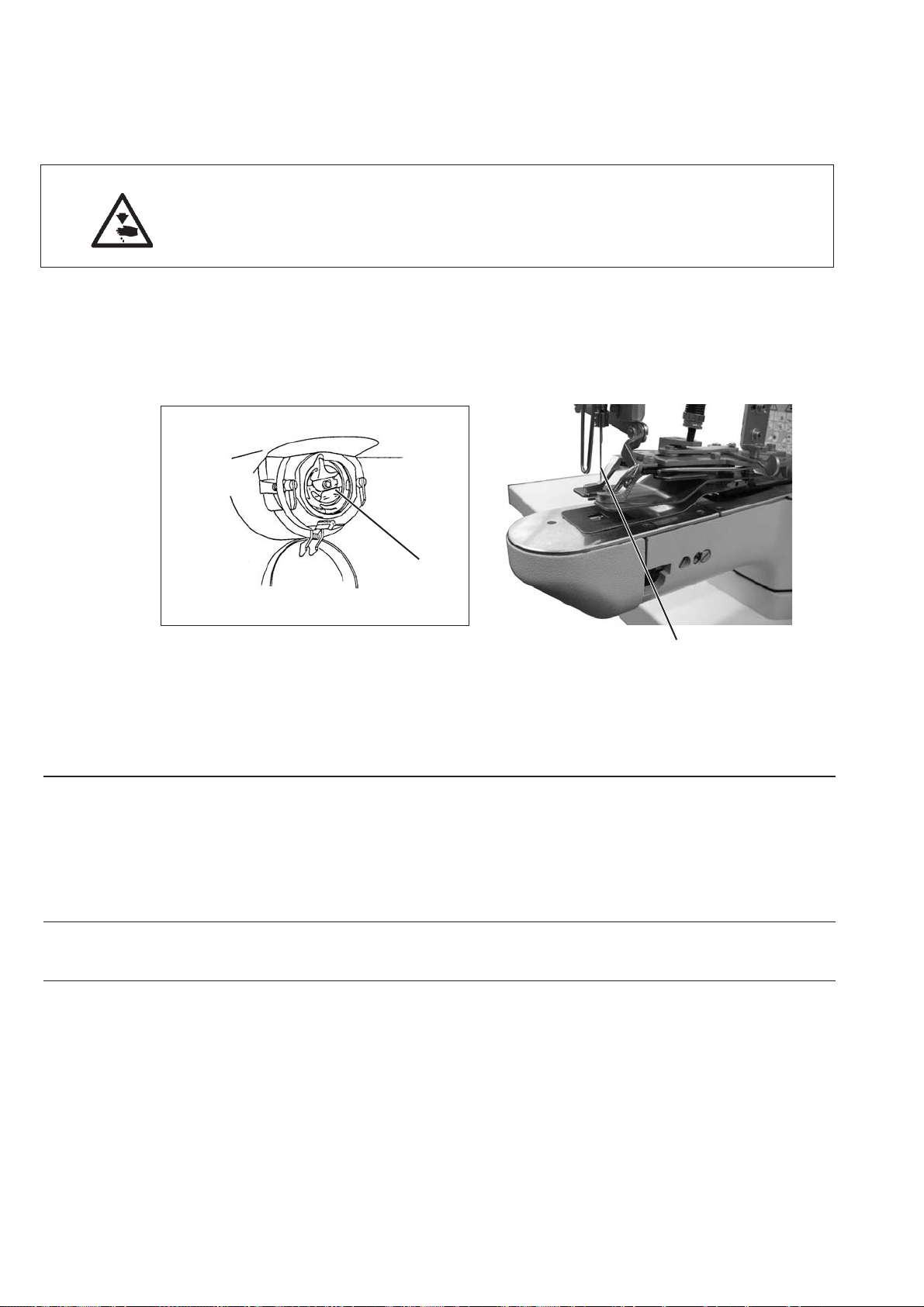
10 Maintenance
10.1 Cleaning and checking
Caution, danger of injury!
Switch the main switch off.
The locking unit must only be maintained when it is switched off.
Maintenance work must be done no later than the maintenance
intervals specified in the tables (see “Operating hours” column).
When dealing with very fluffy materials shorter maintenance intervals
may be necessary.
A clean locking unit protects against malfunctions.
1
2
Maintenance work Explanation Operating
to be carried out hours
Top of machine
8
- Remove sewing dust a nd loose
threads.
(e.g. with compressed air gun)
Control box
Places to be cleaned particularly:
- Underside of stitch plate
- Area under the hook 1
- Bobbin housing
- Thread cutter
- Area under the needle 2
- Keep ventilation filters clear
8
90
Page 93

10.2 Oil lubrication
321
1
Caution, danger of injury!
Oil can cause skin rashes.
Avoid excessive contact with the skin.
Wash thoroughly after contact.
CAUTION!
Handling and disposing of mineral oils is s ubject to statutory
regulations.
Take used oil to an authorised receiving center.
Protect the environment.
Ensure that you do not spill any oil.
Only use lubrication oil DA 10 or a similar oil with the following
specifications to lubricate the locking unit:
–
Viscosity at 40°C: 10 mm²/s
–
Flash point: 150°C
DA 10 can be obtained from DÜRKOPP ADLER AG sales centers
under the following part numbers:
20 ml container: 9047 000011
1 litre container: 9047 000012
2 litre container: 9047 000013
5 litre container: 9047 000014
Maintenance work Explanation Operating
to be carried out hours
Lubricating the button
sewing attachment
The button sewer is fitted with a central oil
wick lubrication system. The bearing points
are supplied from oil reservoirs 2 and 3.
8
- The oil level must not go below the red
line on the two oil reservoirs
.
- Top up with oil through hole 1 up to the red
line.
91
Page 94

11. Standard sewing patterns
No. Stitch pattern Stitch number of standard size Standard size
distribution Connecting threads x direction (mm) Y direction (mm)
15-613.43.4
27-813.43.4
37-833.43.4
49-1013.43.4
5 11 - 12 1 3.4 3.4
65-503.43.4
77-703.43.4
89-903.43.4
9 11 - 11 0 3.4 3.4
10 5 - 5 1 3.4 3.4
11 7 - 7 1 3.4 3.4
12 9 - 9 1 3.4 3.4
13 5 - 6 1 3.4 3.4
14 7 - 8 1 3.4 3.4
15 9 - 10 1 3.4 3.4
16 11 - 12 1 3.4 3.4
17 5 - 5 0 3.4 3.4
18 7 - 7 0 3.4 3.4
19 9 - 9 0 3.4 3.4
20 5 - 5 1 3.4 3.4
21 7 - 7 1 3.4 3.4
92
Page 95

No. Stitch pattern Stitch number of standard size Standard size
distribution Connecting threads x direction (mm) Y direction (mm)
22 9 - 9 1 3.4 3.4
23 11 - 11 1 3.4 3.4
24 5 - 3.4
25 7 - 3.4
26 9 - 3.4
27 11 - 3.4
28 15 - 3.4
29 19 - 3.4
30 6 - - 3.4
31 10 - - 3.4
32 12 - - 3.4
33 5 - 6 1 3.4 3.4
34 9 - 10 1 3.4 3.4
35 5 - 5 0 3.4 3.4
36 9 - 9 0 3.4 3.4
37 5-5-4 - 2.9 2.5
38 8-8-7 - 2.9 2.5
1
39 5-5-4 - 2.9 2.5
40 8-8-7 - 2.9 2.5
41 6 x 4 - 3.5 4.0
42 6 x 6 - 3.5 4.0
43 5 - 5 5 - 5 - 3.5 4.0
93
Page 96

No. Stitch pattern Stitch number of standard size Standard size
distribution Connecting threads x direction (mm) Y direction (mm)
44 7 - 7 7 - 7 - 3.5 4.0
45 3-4-4 - 3.4 3.4
46 4-4-3 - 3.4 3.4
47 3-4-3 - 3.4 3.4
48 3-4-3 - 3.4 3.4
49 6-6-6-5 - 3.4 3.4
50 8-8-8-7 - 3.4 3.4
94
Page 97
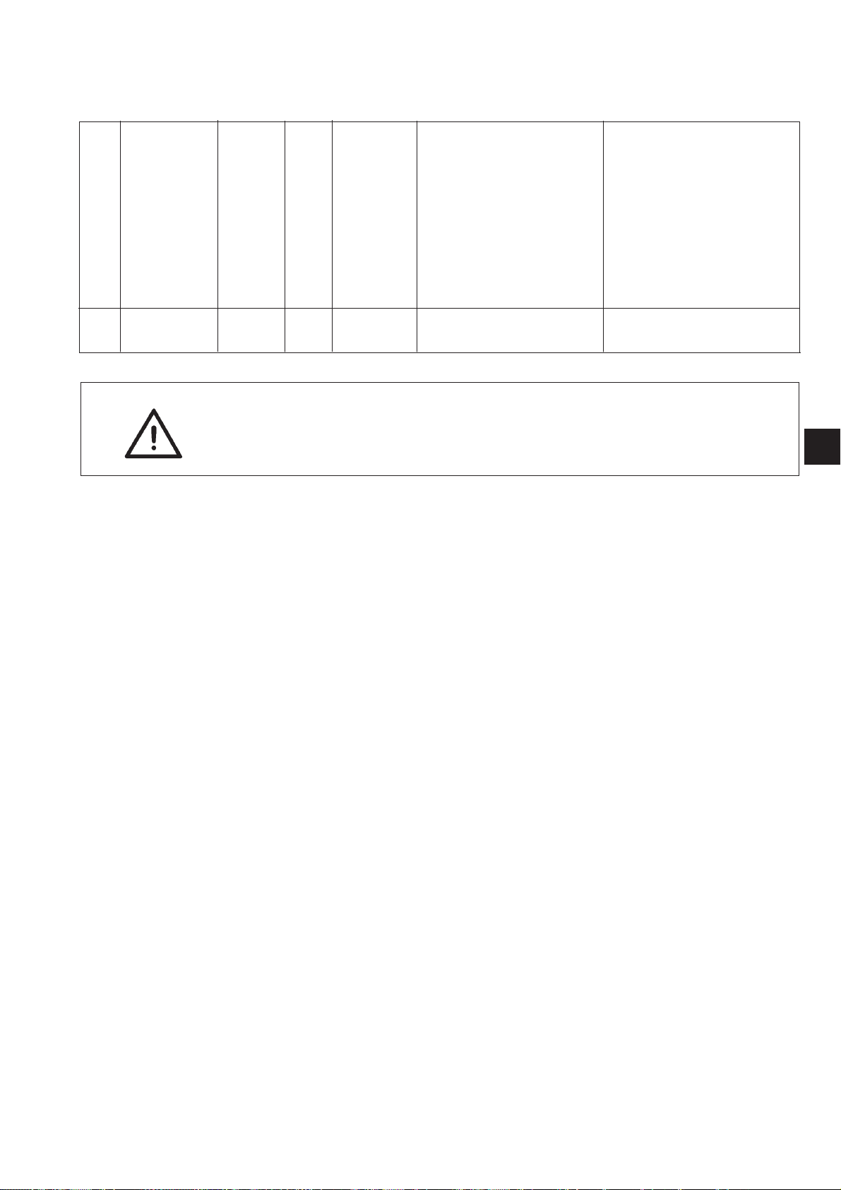
12. Clamping feet
Clamping foot number
1 10x10 yes 1 all buttonclamps
Dimensions X x Y [mm]
Material support plate
opening
Rectangular inner
frame
Standard sewing
pattern number
parameter
For technical reasons and to provide a s afety margin the sewing
·
field is smaller than the material support plate opening.
permissible
standard sewing
patterns
Description
1
95
Page 98

13 Repair
When the machine is damaged or parts are wor n please contact:
DÜRKOPP ADLER AG
Potsdamer Str. 190
D-33719 Bielefeld
Phone: +49 (0) 180 5 383 756
Fax: +49 (0) 521 925 2594
E-mail: service@duerkopp-adler.com
Internet: www.duerkopp-adler.com
96
 Loading...