

Duerkopp Adler 530 Service Manual

530
CNC Knopfannähautomat
CNC Automat for Button Sewing
Bedienanleitung / Operating Instructions
Aufstellanleitung / Installation Instructions
Serviceanleitung / Service Instructions
1
2
3
Postfach 17 03 51, D-33703 Bielefeld Potsdamer Straße 190, D-33719 Bielefeld
Telefon +49 (0) 5 21/ 9 25-00 Telefax+49(0)521/9252435 www.duerkopp-adler.com
Ausgabe / Edition: Änderungsindex Teile-Nr./Part.-No.:
06/2008 Rev. index: 01.0 Printed in Federal Republic of Germany 0791 530001

Anleitung, komplett
Manual, complete
530
Übersicht Summary
Bedienanleitung
Aufstellanleitung
Serviceanleitung
Bauschaltplan
9890 510001 B
Operating Instructions
Installation Instructions
Service Instructions
Interconnection-diagram
9890 510001 B
Alle Rechte vorbehalten.
Eigentum der Dürkopp Adler AG und urheberrechtlich geschützt. Jede, auch auszugsweise
Wiederverwendung dieser Inhalte ist ohne vorheriges schriftliches Einverständnis der Dürkopp Adler AG
verboten.
All rights reserved.
Property of Dürkopp Adler AG and copyrighted. Reproduction or publication of the content in any manner,
even in extracts, without prior written permission of Dürkopp Adler AG, is prohibited.
Copyright ©
Dürkopp Adler AG - 2008

Foreword
This instruction manual is intended to help the user to become familiar
with the machine and take advantage of its application possibilities in
accordance with the recommendations.
The instruction manual contains important information on how to
operate the machine securely, properly and economically. Observation
of the instructions eliminates danger, reduces costs for repair and
down-times, and increases the reliability and life of the machine.
The instruction manual is intended to complement existing national
accident prevention and environment protection regulations.
The instruction manual must always be available at the machine/sewing
unit.
The instruction manual must be read and applied by any person that is
authorized to work on the machine/sewing unit. This means:
– Operation, including equipping, troubleshooting during the work
cycle, removing of fabric waste,
– Service (maintenance, inspection, repair) and/or
– Transport.
The user also has to assure that only authorized personnel work on the
machine.
The user is obliged to check the machine at least once per shift for
apparent damages and to immediatly report any changes (including the
performance in service), which impair the safety.
The user company must ensure that the machine is only operated in
perfect working order.
Never remove or disable any safety devices.
If safety devices need to be removed for equipping, repairing or
maintaining, the safety devices must be remounted directly after
completion of the maintenance and repair work.
Unauthorized modification of the machine rules out liability of the
manufacturer for damage resulting from this.
Observe all safety and danger recommendations on the machine/unit!
The yellow-and-black striped surfaces designate permanend danger
areas, eg danger of squashing, cutting, shearing or collision.
Besides the recommendations in this instruction manual also observe
the general safety and accident prevention regulations!

General safety instructions
The non-observance of the following safety instructions can cause
bodily injuries or damages to the machine.
1. The machine must only be commissioned in full knowledge of the
2. Before putting into service also read the safety rules and
3. The machine must be used only for the purpose intended. Use of
4. When gauge parts are exchanged (e.g. needle, presser foot, needle
5. Daily servicing work must be carried out only by appropriately
instruction book and operated by persons with appropriate training.
instructions of the motor supplier.
the machine without the safety devices is not permitted. Observe all
the relevant safety regulations.
plate, feed dog and bobbin) when threading, when the workplace is
left, and during service work, the machine must be disconnected
from the mains by switching off the master switch or disconnecting
the mains plug.
trained persons.
6. Repairs, conversion and special maintenance work must only be
carried out by technicians or persons with appropriate training.
7. For service or repair work on pneumatic systems, disconnect the
machine from the compressed air supply system (max. 7-10 bar).
Before disconnecting, reduce the pressure of the maintenance unit.
Exceptions to this are only adjustments and functions checks made
by appropriately trained technicians.
8. Work on the electrical equipment must be carried out only by
electricians or appropriately trained persons.
9. Work on parts and systems under electric current is not permitted,
except as specified in regulations DIN VDE 0105.
10. Conversion or changes to the machine must be authorized by us
and made only in adherence to all safety regulations.
11. For repairs, only replacement parts approved by us must be used.
12. Commissioning of the sewing head is prohibited until such time as
the entire sewing unit is found to comply with EC directives.
13. The line cord should be equipped with a country-specific mains
plug. This work must be carried out by appropriately trained
technicians (see paragraph 8).
It is absolutely necessary to respect the safety
instructions marked by these signs.
Danger of bodily injuries !
Please note also the general safety instructions.

Index Page:
Part 3: Service Instructions Class 530
1. General notes ................................................ 3
2. Arm shaft
2.1 Preparatorywork............................................... 4
2.2 Assemblyofthecrank............................................ 5
2.3 Armshaftposition .............................................. 6
2.4 Bevel gear for the handwheel ....................................... 8
2.5 Adjust bobbin winder............................................. 9
2.6 Threadtrimmercam............................................. 10
2.7 Crankshaft drive to the hook shaft..................................... 11
2.8 Sewing motor coupling ........................................... 12
2.9 Referencepositionofthesewingmotor................................. 13
2.9.1 Positionoftheinitiator............................................ 13
2.9.2 Adjustreferenceposition.......................................... 14
3. Hook, looping stroke and needle bar height
3.1 Drivershaft .................................................. 17
3.2 Gearsegmentonthecamshaft ...................................... 18
3.3 Gearsegmenttothedrivershaft...................................... 19
3.4 Needle bar height............................................... 20
3.5 Distance between hook tip and needle .................................. 21
3.6 Looping stroke and needle guard ..................................... 22
4. Thread-guiding parts
4.1 Threadcontrollerspring........................................... 23
4.2 Thread regulator ............................................... 25
4.3 Change thread wiper............................................. 26
4.3.1 Threadwiperheight............................................. 26
5. Thread trimmer
5.1 Thread trimmer magnet ........................................... 27
5.2 Position of the hook knife .......................................... 28
5.3 Cutting pressure / Position of the stationary knife ........................... 29
5.4 Thread guiding sheet ............................................ 31
5.5 Threadtrimmer................................................ 32
3
6. Material feed
6.1 Gauge for reference position ........................................ 33
6.2 Referenceposition.............................................. 34
6.3 Position of the fabric clamps and the rest plate to the needle .................... 36

Index Page:
7. Oil lubrication
7.1 Oilcirculation................................................. 38
7.2 Lubricating oil pump ............................................. 39
8. Maintenance ................................................. 40

1. General notes
The service instructions on hand describe the adjustment of the button
sewing automat 530.
ATTENTION !
The operations described in the service instructions may only be
carried out by qualified staff or other appropriately trained persons!
Caution: Danger of injury !
In case of repair, alteration and maintenance work switch off
main switch.
Carry out adjusting operations and functional tests of the running
machine only under observation of all safety measures and with
utmost caution.
These service instructions describe the adjustment of the button
sewing automat in a logical order. Please observe in this connection
that various setting positions are interdependent. The adjustment
process must therefore be carried out int the order given.
For all setting operations of parts involved in the stitch formation a new
needle without any damage has to be inserted.
3
3
2. Arm shaft
2.1 Preparatory work
1
Some of the adjustments at the arm shaft 1 can be carried out easier if
the thread trimming mechanism 3 is removed before.
Caution: Danger of injury !
Switch off main switch.
Remove and mount thread trimming mechanism only when the button
sewing automat is switched off.
Remove mechanism
–
Unscrew arm cover.
–
Loosen screw 4 at the thread trimmer magnet.
–
Unscrew screws 2 and 5 and take off thread trimming
mechanism 3.
Mount mechanism
–
Push thread trimming mechanism 3 on the magnet and place it on
the machine head.
–
Insert screws 2 and 5 and screw tight.
–
Tighten screw 4 at the thread trimmer magnet.
–
Adjust thread trimmer (see chapter 5).
5432
4
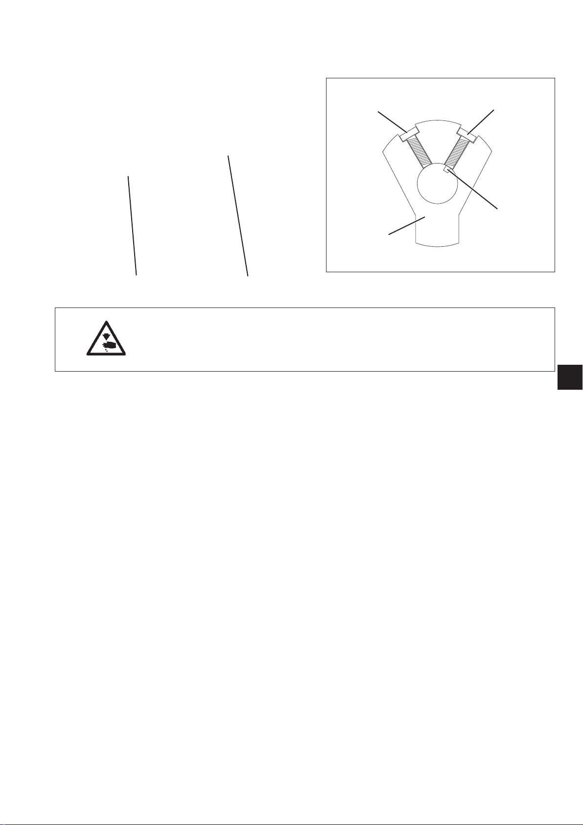
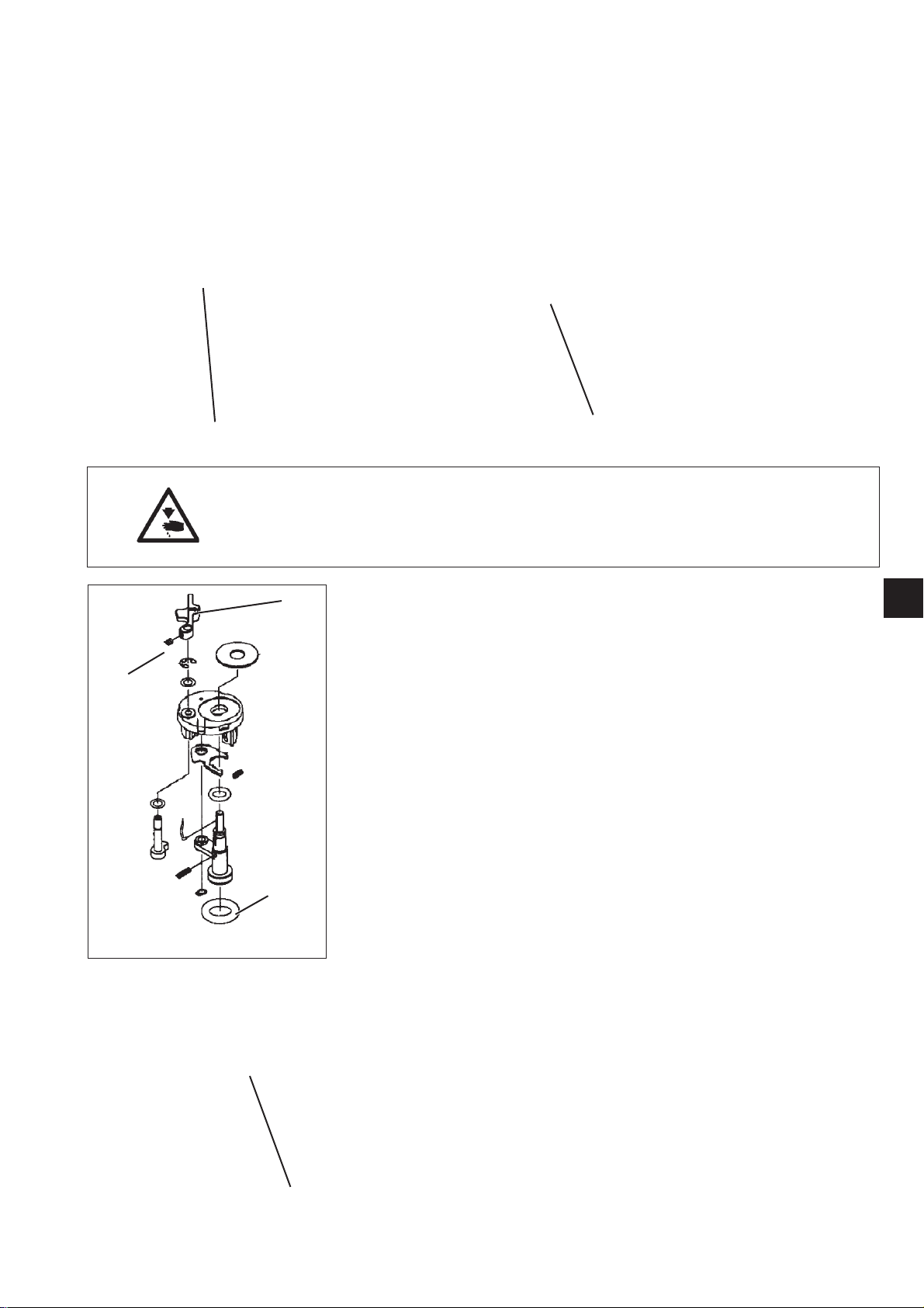
2.2 Assembly of the crank
41
Caution: Danger of injury !
Switch off main switch.
Remove and mount crank only when the button sewing automat is
switched off.
5
2
3
4
3
Standard
The crank 4 has to be mounted on the arm shaft 1 in such a way that
the pivot 3 of the screw 2 reaches into the drill-hole on the arm shaft.
The screw 2 is the first screw in the direction of rotation.
Assembly
–
Push crank 4 on arm shaft 1.
–
Twist crank 4 in such a way that its first drill-hole in the direction of
rotation lies above the drill-hole in the arm shaft 1. Insert screw 2
with pivot 3 and screw tight.
–
Insert screw 5 and tighten.
5
2.3 Arm shaft position
1
Caution: Danger of injury !
Switch off main switch.
Check and adjust position of the arm shaft only when the button
sewing automat is switched off.
Standard checking
The arm shaft 1 should have no axial backlash, but it must not move
too heavy.
–
Check the arm shaft with regard to axial backlash and rough
running.
Correction
8
6 543 2
–
–
–
–
6
3
Loosen screws at the thread trimmer cam 2.
Loosen screws at the adjusting ring 3.
Loosen screws at the bevel gear 4.
Loosen screws at the bobbin winder wheel 5.

8
6 543 2
–
Loosen screw at the motor coupling 7.
–
Push arm shaft cam 6 axially to the right as far as it will go.
–
Push adjusting ring 3 to the left against the bearing bush and
tighten screws.
–
Check arm shaft with regard to axial backlash and smooth running.
–
Tighten screws at the thread trimmer cam 2
(adjustment see c hapter 5).
–
Tighten screws at the bevel gear 4
(adjustment see chapter 2.2).
–
Tighten screws at the bobbin winder wheel
(adjustment see chapter 2.3).
–
Tighten screw at the motor coupling 7
(adjustment see chapter 2.6 ).
7
3
3
7
2.4 Bevel gear for the handwheel
1
Caution: Danger of injury!
Switch off main switch.
Check and adjust bevel gear only when the button sewing
automat is switched off.
Standard checking
The bevel gear 1 has to be positioned on the upper shaft in such a way
that - when the handwheel 2 is engaged - there is as little clearance as
possible between bevel gear 1 and bevel gear 3.
–
Engage handwheel 2.
–
Check whether there is as little clearance as possible between
bevel gear 1 and bevel gear 3.
Correction
–
Loosen screws at bevel gear 1.
–
Engage handwheel 2.
–
Press bevel gear 1 against the toothed wheel 3 and tighten
fastening screws.
–
Turn handwheel and check whether there is as little clearance as
possible between bevel gear 1 and toothed wheel 3.
132
8
2.5 Adjust bobbin winder
1
Caution: Danger of injury!
Switch off main switch.
Check and adjust bobbin winder only when the button sewing
automat is switched off.
4
3
2
Standard
The bobbin winding operation must stop automatically when the bobbin
is filled up to approx. 0.3 mm below the edge of the bobbin.
Correction of the bobbin winder wheel
–
Loosen screws at the driver wheel 1.
–
Shift driver wheel 1 axially in such a way that it abuts on the bobbin
winder wheel 2 with the bobbin cover screwed on .
–
Tighten screws at the driver wheel 1.
The second screw in the direction of rotation is located at a
spot-faced place.
–
Put on head cover and tighten.
–
Check bobbin winder and repeat adjustment, if necessary.
Correction of the bobbin capacity
–
Loosen screw 3.
–
Adjust bobbin winder clip 4.
–
Tighten screw 3.
1
3
Note:
When correcting the driver wheel take care that the oil wicks do not
collide with the driver wheel afterwards.
1
9
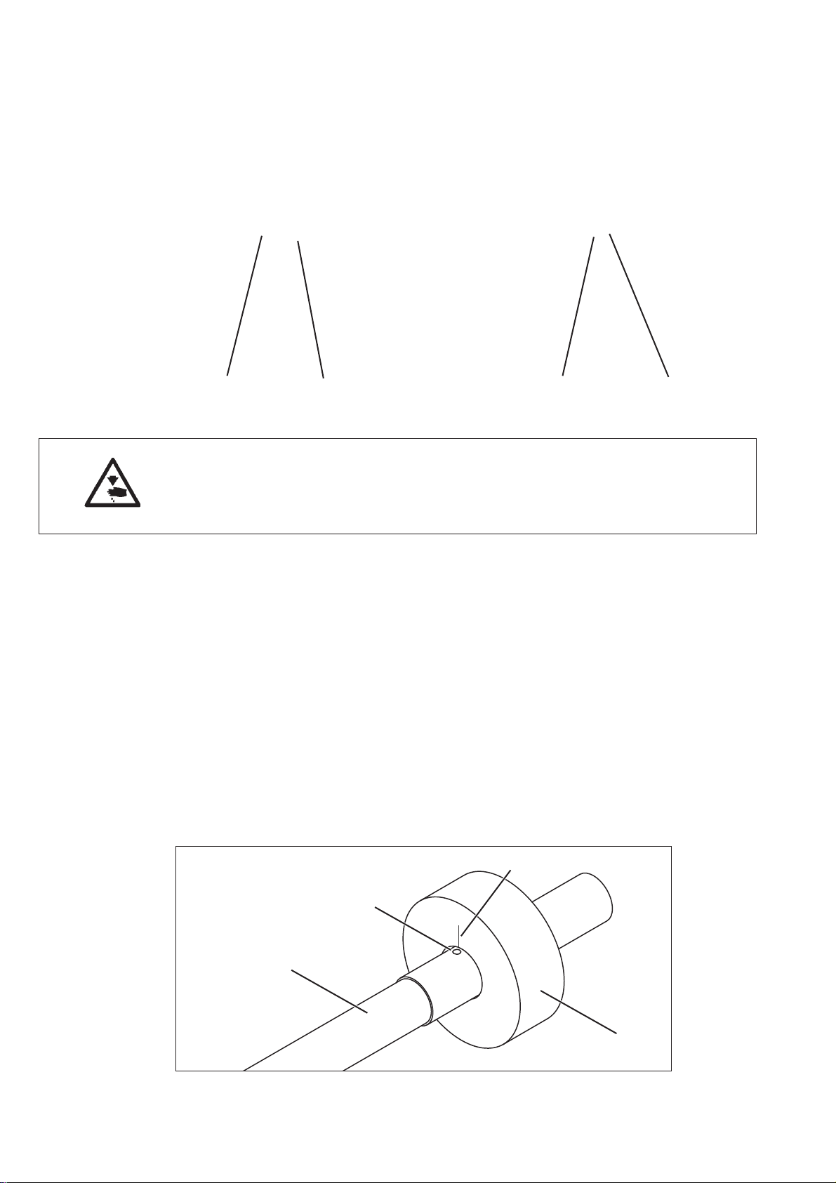
2.6 Thread trimmer cam
21
Caution: Danger of injury!
Switch off main switch.
Check and adjust thread trimmer cam only when the button sewing
automat is switched off.
Standard checking
The correct position of the thread trimmer cam 1 is marked by a point
on the upper shaft 2 and a line on the thread trimmer cam 1.
The position is correct when both markings are standing opposite.
–
Engage handwheel and turn until the marking points 4 and 5 on the
upper shaft and the thread trimmer cam are visible.
–
Check whether both markings are s tanding exactly opposite.
Correction
–
Loosen screws 3 at the thread trimmer cam.
–
Twist and axially shift the thread trimmer cam in such a way that
both markings 4 and 5 are standing exactly opposite.
–
Tighten screws 3.
31
10
5
4
2
1
 Loading...