


52Xi
Industrial sewing machine
Instruction manual
Betriebsanleitung
GB
D
Postfach 17 03 51, D-33703 Bielefeld • Potsdamer Straße 190, D-33719 Bielefeld
Telefon +49 (0) 521 / 9 25-00 • Telefax +49 (0) 521 / 9 25 24 35 • www.duerkopp-adler.com
Ausgabe / Edition: Aenderungsindex Teile-Nr./Part.-No.:
03/2010 Rev. index: 02.0 Printed in Czech Republic S735 000800

All rights reserved.
Property of Dürkopp Adler AG and copyrighted. Reproduction or publication of the content in any manner, even
in extracts, without prior written permission of Dürkopp Adler AG, is prohibited.
Alle Rechte vorbehalten.
Eigentum der Dürkopp Adler AG und urheberrechtlich geschützt. Jede, auch auszugsweise Wiederverwendung
dieser Inhalte ist ohne vorheriges schriftliches Einverständnis der Dürkopp Adler AG verboten.
Copyright ©
Dürkopp Adler AG - 2010

Foreword
This instruction manual is intended to help the user to become familiar
with the machine and take advantage of its application possibilities in
accordance with the recommendations.
The instruction manual contains important information on how to
operate the machine securely, properly and economically. Observation
of the instructions eliminates danger, reduces costs for repair and
down-times, and increases the reliability and life of the machine.
The instruction manual is intended to complement existing national
accident prevention and environment protection regulations.
The instruction manual must always be available at the machine/sewing
unit.
The instruction manual must be read and applied by any person that is
authorized to work on the machine/sewing unit. This means:
– Operation, including equipping, troubleshooting during the work
cycle, removing of fabric waste,
– Service (maintenance, inspection, repair) and/or
– Transport.
The user also has to assure that only authorized personnel work on the
machine.
The user is obliged to check the machine at least once per shift for
apparent damages and to immediatly report any changes (including the
performance in service), which impair the safety.
The user company must ensure that the machine is only operated in
perfect working order.
Never remove or disable any safety devices.
If safety devices need to be removed for equipping, repairing or
maintaining, the safety devices must be remounted directly after
completion of the maintenance and repair work.
Unauthorized modification of the machine rules out liability of the
manufacturer for damage resulting from this.
Observe all safety and danger recommendations on the machine/unit!
The yellow-and-black striped surfaces designate permanend danger
areas, eg danger of squashing, cutting, shearing or collision.
Besides the recommendations in this instruction manual also observe
the general safety and accident prevention regulations!

General safety instructions
The non-observance of the following safety instructions can cause
bodily injuries or damages to the machine.
1. The machine must only be commissioned in full knowledge of the
2. Before putting into service also read the safety rules and
3. The machine must be used only for the purpose intended. Use of
4. When gauge parts are exchanged (e.g. needle, presser foot, needle
5. Daily servicing work must be carried out only by appropriately
instruction book and operated by persons with appropriate training.
instructions of the motor supplier.
the machine without the safety devices is not permitted. Observe all
the relevant safety regulations.
plate, feed dog and bobbin) when threading, when the workplace is
left, and during service work, the machine must be disconnected
from the mains by switching off the master switch or disconnecting
the mains plug.
trained persons.
6. Repairs, conversion and special maintenance work must only be
carried out by technicians or persons with appropriate training.
7. For service or repair work on pneumatic systems, disconnect the
machine from the compressed air supply system (max. 7-10 bar).
Before disconnecting, reduce the pressure of the maintenance unit.
Exceptions to this are only adjustments and functions checks made
by appropriately trained technicians.
8. Work on the electrical equipment must be carried out only by
electricians or appropriately trained persons.
9. Work on parts and systems under electric current is not permitted,
except as specified in regulations DIN VDE 0105.
10. Conversion or changes to the machine must be authorized by us
and made only in adherence to all safety regulations.
11. For repairs, only replacement parts approved by us must be used.
12. Commissioning of the sewing head is prohibited until such time as
the entire sewing unit is found to comply with EC directives.
13. The line cord should be equipped with a country-specific mains
plug. This work must be carried out by appropriately trained
technicians (see paragraph 8).
It is absolutely necessary to respect the safety
instructions marked by these signs.
Danger of bodily injuries !
Please note also the general safety instructions.

Table of contents Page
Part 2 - Installation Instructions - 52Xi
1. Scope of machine supply ........................................ 3
2. Complete machine transport packing ................................ 4
3. Stand assembly
3.1 Standframeassembly ........................................... 4
3.2 Tabletopassembly ............................................. 5
3.2.1 Mounting of table top with clutch motor ................................. 5
3.2.2 Mounting of table top with DC1550/DA321G positioning motor ................... 6
3.2.3 Mounting of table top with integrated drive on machine head .................... 7
3.3 Standheightsetting ............................................ 8
4. Machine head fixing
4.1 Machine head fixing into stand ...................................... 9
4.1.1 Motor under table top ............................................ 9
4.1.2 Motor integrated on machine head .................................... 9
4.1.3 Adjustmentofmachineblockingswitch................................. 10
4.2 Mounting of V-belt driven machine head ................................ 11
4.3 Mounting of belt guards .......................................... 13
4.4 Mounting of positioning motor control panel .............................. 14
4.5 Mounting of connecting cable ....................................... 15
4.6 Mounting o f lighting lamp .......................................... 16
5. Machine electric connection
5.1 Machine connection to low voltage network .............................. 17
5.1.1 Connection of lighting transformer to network voltage ........................ 18
5.2 Grounding ................................................... 19
5.3 Connection of sewing head to EFKA DC1550/DA321G motor ................... 20
6. Setting of Efka positioning motor
6.1 Settingofpositioningmotorparameters ................................ 21
6.1.1 Setting of parameters through “autoselect” function ......................... 21
6.1.2 SettingofEfkamotorparameters..................................... 21
6.1.3 Parametervalues.............................................. 22
6.2 Settingofmachinepositioning ...................................... 22
6.2.1 Positiondefinition.............................................. 22
6.2.2 Setting of machine positioning for DC1550/DA321G motor ..................... 23
6.2.3 Checkingofsetpositions ......................................... 23
6.3 Masterreset ................................................. 23
7. Machine lubrication ............................................ 23
8. Sewing test ................................................. 23

For your notes:
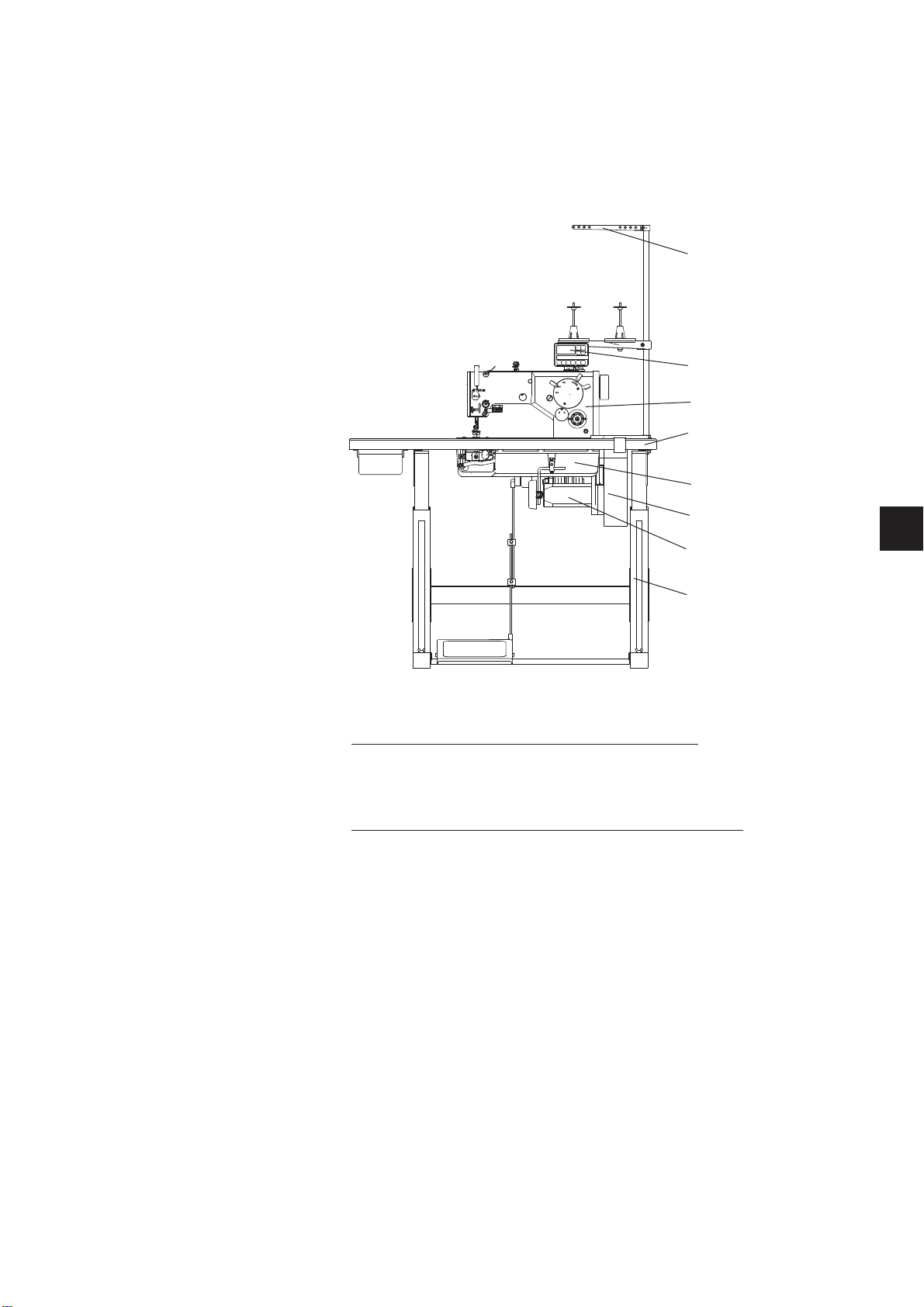
1. Scope of machine supply
The purchaser can order a complete machine or just some of the
components. Check before installation whether all parts are available.
These instructions describe assembly of a partly disassembled
machine the components of which are completely supplied by the
company Dürkopp Adler AG.
3
6
1
7
2
5
4
8
Obligatory components: (they are always supplied)
–
Sewing head (1)
–
Accessories (include oil tray (2), yarn stand (3), positioning motor
connecting cable /if there is any/, tools and other items)
Optional components: (they are supplied on request only)
–
Complete motor (includes motor (4), V-belt pulley, positioning
motor control box (5) or switch-circuit-breaker, electric cables)
–
Positioning motor control panel (6) /if there is any/
–
Stand/includes table top (7) and frame (8)/
GB
3
2. Complete machine transport packing
If the sewing machine is supplied as a complete machine, the following
transport packing must be removed:
–
safety straps and wooden slats on machine head and stand
–
safety blocks and straps on sewing drive
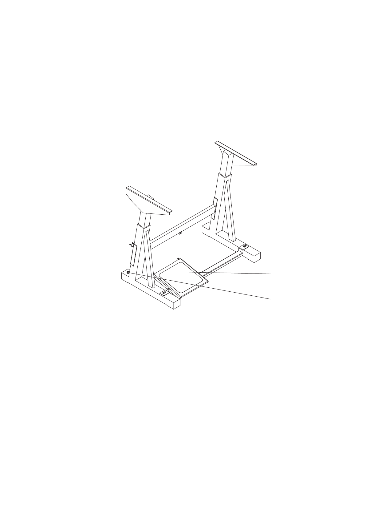
3. Stand assembly
3.1 Stand frame assembly
1
2
–
Assemble the frame according to the picture. Mount the pedal (1)
provisionally. Its position will be adjusted after the whole machine
is complete.
–
Adjust the bolt (2) so that the stand is stable.
4
3.2 Stand table assembly
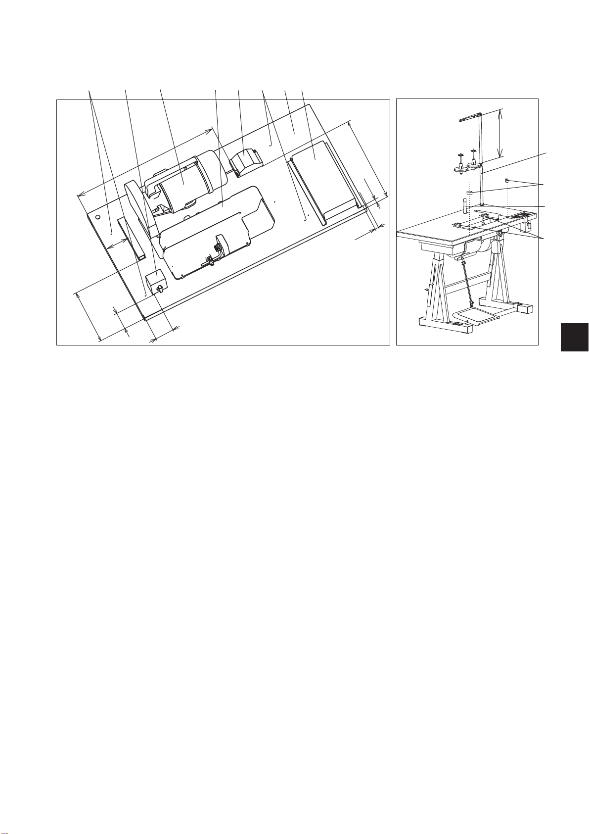
3.2.1 Mounting of table top with clutch motor
764 35712
250
100
80
640
80
390
15
15
–
Turn the table top (1) upper side down.
–
Screw the drawer (2) on.
–
Set the oil tray (3) so that the oil tray inside aligns with the recess
380
in the table top and screw it on.
–
Screw the clutch motor(4) on.
–
Screw the lighting transformer (5) on - attachment.
–
Screw the switch (6) on.
–
Mount electric cables according to section 5 of these Instructions
and fix them to the stand table top with clamps.
–
Screw the stand frame to the table top - pre-drilled holes (7).
Then turn the stand to the normal position.
–
Mount the yarn stand (8) according to the picture, insert it into the
hole in the table top and fix it with a nut with washer.
–
Fix the machine head support (9).
–
Stick rubber hinge bottoms (10) and rubber corners (11) with a
suitable contact glue. Stick horizontal fitting surfaces of the hinge
bottoms only. You can also fix the hinge bottoms by means of wood
screws which must be then screwed down so deep so that there is
no contact of the wood screws and the machine head.
8
11
9
10
GB
5

3.2.2 Mounting of table top with DC1550/DA321G positioning motor
98 54 6 3 79 1 2
640
430
390
380
10
120
500
490
49
100
15
15
–
Turn the table top (1) upper side down.
–
Screw the drawer (2) on.
–
Set the oil tray (3) so that the oil tray inside aligns with the recess
in the table top and screw it on.
–
Screw the motor(4) on.
–
Screw the motor control box (5) on.
–
Screw the set value sensor (6) on.
–
Screw the lighting transformer (7) on - /attachment/.
–
Screw the cable canal (8) on.
–
Mount the electric cables according to section 5 of these
Instructions and fix them to the table top with clamps.
–
Screw the stand frame to the table top - pre-drilled holes (9).
Then turn the stand to the normal position.
–
Mount the yarn stand (10) according to the picture, insert it into the
hole in the table top and fix it with a nut with washer.
–
Fix the support blinds (11).
–
Stick rubber hinge bottoms (12) and rubber corners (13) with a
suitable contact glue. Stick horizontal fitting surfaces of the hinge
bottoms only. You can also fix the hinge bottoms by means of wood
screws which must be then screwed down so deep so that there is
no contact of the wood screws and the machine head.
13
11
12
6

3.2.3 Mounting of table top with integrated drive on machine head
98 4 56 3 79 1 2
640
430
195
390
120
500
490
355
49
15
15
100
–
Turn the table top (1) upper side down.
–
Screw the drawer (2) on.
–
Set the oil tray (3) so that the oil tray inside aligns with the recess
in the table top and screw it on.
–
Screw the microswitch (4) on.
–
Screw the motor control box (5) on.
–
Screw the set value sensor (6) on.
–
Screw the lighting transformer (7) on - /attachment/.
–
Screw the cable canal (8) on.
–
Mount the electric cables according to section 5 of these
Instructions and fix them to the table top with clamps.
–
Screw the stand frame to the table top - pre-drilled holes (9).
Then turn the stand to the normal position.
–
Mount the yarn stand (10) according to the picture, insert it into the
hole in the table top and fix it with a nut with washer.
–
Fix the support blinds (11).
–
Stick rubber hinge bottoms (12) and rubber corners (13) with a
suitable contact glue. Stick horizontal fitting surfaces of the hinge
bottoms only. You can also fix the hinge bottoms by means of wood
screws which must be then screwed down so deep so that there is
no contact of the wood screws and the machine head.
GB
7

3.3 Stand height setting
–
The stand height is adjustable between 750 and 900 mm.
–
Loosen the screws (1).
–
Set the required table top height and make sure that it is identical
on both sides. To do so, make use of the scale on the stand feet.
Set the stand height so that it corresponds with the operator´s
bodily proportions.
1
Attention! Danger of injury!
Failure to adjust the stand height to the operator´s bodily proportions
may result in damage of the operator´s locomotive organs.
–
Tighten the screws (1).
8

4. Machine head assembly
4.1 Machine head fixing into stand
4.1.1 Motor under table top
–
Insert the machine head (1) in the recess in the table top according
to the picture.
1
GB
4.1.2 Motor integrated on machine head
3
4
1
2
–
Tilt the machine head (1) slightly and insert it in the recess in the
table top.
–
After inserting the machine head (1) into the inserts (2) /tilt
position/ loosen the screw ((3) and slide the prop (4) up to a stop
and tighten the screw (3).
9

4.1.3 Adjustment of machine blocking switch
D
1
2
–
The maschine adjust so that, the microswitch must be switched on
in the machine working position.
–
Loosen the screws (1), the microswitch shifting in the groove (2)
until the sound of the switch switching (a click) is heard.
–
Tighten the screws (1).
10

4.2 Mounting of V-belt driven machine head
15 mm
F=10N
2
3
3
1
4
–
Mount the V-belt pulley (1) which is a part of the motor supply - if it
was ordered from the supplier Dürkopp Adler. The belt pulley
should have dimensions according to the table below.
–
Fix the V-belt (2), loosen the screw (3) and stretch the belt.
–
Check the belt tension with force F = 10 N (~ 1 kg). The belt should
bend approximately by 15 mm.
–
Adjust the position of the stop (4) on the belt guard to the distance
approximately 3 mm from the belt pulley so that it prevents the belt
falling out of the belt pulley groove at the machine head tilting.
GB
11

Belt pulley selection according to the motor and machine class
FIR 1148/552/3 motor, power frequency 50 Hz, motor speed 2800 rpm
Data unit 523i 524i 525i 527i
operating sewing speed rpm 3230 3230 3230 2150
belt pulley outer diameter mm 80 80 80 55
belt pulley order number - S980 000050 S980 000050 S980 000050 S980 000189
FIR 1148/552/3 motor, power frequency 60 Hz, motor speed 3360 rpm
Data unit 523i 524i 525i 527i
operating sewing speed rpm 3880 3880 3880 2580
belt pulley outer diameter mm 80 80 80 55
belt pulley order number - S980 000050 S980 000050 S980 000050 S980 000189
Efka DC1550/DA321G positioning motor
Data unit 523i 524i 525i 527i
operating sewing speed rpm 3500 3500 3500 2000
belt pulley outer diameter mm 84 84 75 75
belt pulley order number - 9130 500770 9130500770 9130 500750 9130 500750
12

4.3 Mounting of belt guards
1
3
5
6
2
4
3
7
–
If the machine is equipped with the positioning motor, first mount
pins (2) on the belt guard (1) /they are included in the accessories/.
–
Partly screw two screws (3) in the machine head.
–
Fix the belt guard (1), screw the screw (4) down and slightly tighten
all fastening screws.
–
If the machine is not equipped with the positioning motor,
fix the proximity switch (5), which is a part of the motor supply,
on the pin inside the hand wheel to the stop. Make sure that the
peg (2) fits to the proximity switch fork. Fix the proximity switch
with three screws (6).
–
Pull the proximity switch cable (7) under the table top according to
the picture and subsequently pull it through the cable canal so that
no contact with the V-belt occurs.
GB
13

4.4 Mounting of positioning motor control panel
1
3
2
–
The control panel (1) is supplied on request with machines with
the positioning motor. The same applies to the panel holder (2).
The illustrated control panel has Efka V810 marking. Also a more
comfortable panel V820 can be mounted on the same holder
(picture in the spare parts catalog).
–
Screw out 2 screws (3) and subseqently screw by them the holder
(2).
–
Screw the panel (1) on the holder (2) and pull its cable under the
table top and subsequently throught the c able canal to the motor
control box.
14

4.5 Mounting of connecting cable
GB
12 3
–
If the machine is equipped with the positioning motor, the machine
head is electrically connected to the motor control box by means of
a connecting cable (1). The connecting cable is included in the
accessories.
–
Remove the distribution case cover (2).
–
Install the connecting cable (1) according to the picture.
–
Connect the connector (3) and mount the distribution box cover
back again.
–
Pull the connecting cable (1) under the table top according to the
picture and connect it to the motor control box.
15

4.6 Lighting installation
3
1
2
–
Screw the roll (2) with the screw (1) to the machine head,
fix the lighting lamp on the roll (2) and tighten with a handle (3).
–
The transformer installation is described in section 3.2.
16

5. Machine electric connection
The machine motor is fed from the low voltage network.
Attention!
All works on the machine electric installation may be performed by an
authorized electrician only.
It is absolutely necessary to study the instructions supplied by the
manufacturer about the motor!
5.1 Machine connection to low voltage network
According to the selected type, the machine motor has a single-phase
or three-phase feeding. If it has a three phase feeding, it includes an
asynchronous motor. In that case it is necessary to adjust the
connection of coils in the motor terminal box (in a star or a triangle) to
the local network voltage.
Attention!
The electric network voltage must comply with the voltage on the motor
label!
The asynchronous motor coil connection must correspond with the
local network voltage.
GB
A low voltage circuit includes the following items:
–
supply plug
–
main switch (in the minimotor drive the main switch is integrated in
the minimotor control box)
–
motor
–
lighting transformer (optionally)
–
cables
A part of these items is included in the motor packing.
The low voltage circuit is to be carried out according to the schedule
which is included in the package “the motor parts set”.
Attention! Danger of electric injury!
The motors may be operated only with a protective c onduit connected
to a protective system capable of function complying with prescriptions
and decrees to prevent personal injuries due to electric current or fire.
The motor operation becomes dangerous if the protective conduit
inside or outside the motor is disrupted. The protection must not be
broken by means of e.g. an extension cord without the protective
conduit.
17

5.1.1 Lighting transformer connection to network voltage
Attention! Danger of electric injury!
The lighting transformer is not switched-off by the main switch
(EN 60 204-31)! At the lighting installation and repair works in the
transformer box, e .g. a fuse replacement, the network plug must be
disconnected from the network unconditionally.
A. The machine is equipped with motors:
FIR 1148 - F752.3
–
Pull the network plug from the socket.
–
Lead the transformer cable to the main switch.
–
Connect the transformer cable according to the electric wiring
schedule which is included in the supply of “parts set” supplied
with the machine head.
–
Stick a self-sticker with safety instructions onto the front side of the
main switch.
B. The machine is equipped with Efka DC1550/DA321G motor
26 5 1
–
Pull the network plug form the socket.
–
Screw out 4 screws on the front plate of the control box.
–
Remove the front plate.
–
Pull the cable of the lighting transformer through the canal (1) in
the control box.
–
Take out the black rubber bushing (2).
–
Pierce the bushing with a screwdriver.
–
Pull the lighting transformer cable through the arisen hole.
–
Put the rubber bushing back again.
–
Gradually push the terminal openers (3) and (4) with a small
screwdriver until the terminals (5) and (6) open.
–
Connect the blue conduit (6) to the terminal and brown conduit (5)
to the terminal.
–
Screw the front plate back again.
–
Fix the lighting transformer cable against plucking out
(e.g. with a stick tape to the network supply cord).
65 4 3
18

5.2 Grounding
1
2
–
The grounding conduit (1) is included in the machine accessories.
–
Connect the conduit (1) to the plug (2) and pull its opposite end
under the table top.
–
Screw the opposite end of the grounding conduit to the respective
grounding point of the motor (marked ).
–
Fasten the conduit to the bottom side of the table top with a clamp.
GB
Attention!
Ensure that the grounding conduit does not touch the driving V-belt
(if there is any).
19

5.3 Machine head connection to EFKA DC1550/DA321G motor
3
4
B2
B18
1
–
Connect the machine head connecting cables to the connector (1).
–
Connect the control panel to the connector (2).
–
Connect the position sensor connector in the motor to the
connector (B2).
–
Connect the motor connector to the connector (3).
–
Connect the pedal position sensor (set value sensor) to the
connector (4).
–
Connect the proximity switch to the connector (B18).
2
20

6. Setting of Efka positioning motor
The function of the positioning motor is determined by its program,
setting of the motor parameters and the machine stop positions.
If the sewing machine is supplied as disassembled, the motor setting
must be performed by the purchaser. If the sewing machine is supplied
as complete, the motor is already set by the sewing machine
manufacturer.
6.1 Setting of positioning motor parameters
Setting of the motor parameters is carried out in two steps. In the first
step, parameters for a group of classes of sewing machines are set by
means of the “autoselect” function. In the second step, some of the s et
parameters change to adjust to the particular class.
6.1.1 Setting of parameters through “autoselect” function
The motor control system is equipped with the “autoselect" device
identifying which sewing machine was connected to the motor (with the
connecting cable). At the motor switch-on, the resistance value of the
resistor, for this purpose located inside the machine head, is
automatically measured. On this base, required parameter values are
automatically set up. If the control s ystem is not capable of identifying
the valid resistance, the motor control will run only with so-called
safety operating functions to prevent the sewing machine damage.
GB
6.1.2 Setting of Efka motor parameters
Attention!
Change of the parameter values must be performed responsibly and
with consideration. A wrongly set control may cause the machine
damage!
Warning!
Through the so-called master-reset (see section 6.3) all parameter
values can be set up back to the pre-set values.
21

6.1.3 Parameter values
The description of parameter entering is in the publication attached by
the motor manufacturer “Efka Operation Instructions” or on the website
www.efka.net.
For machines with gear rate 1:1 and with the toothed belt
Parameter Original value New value Parameter description
290* 0 19 Machine class
270 6 0 Choice of sensor type
111 1000 - Max. sewing speed
170 - - Reference position (see 6.2.1)
190 170 120 Switch on angle of thread trimmer
192 160 140 Delay angle of tensioner release
272 1063 1000 Gear rate
For machines with another gear rate and with another belt
Parameter Original value New value Parameter description
290* 0 19 Machine class
111 1000 - Max. sewing speed
170 - - Reference position (see 6.2.1)
190 170 120 Switch on angle of thread trimmer
192 160 140 Delay angle of tensioner release
* Parameter necessary to be entered as the first.
Warning:
To set parameters higher than 200 it is necessary to enter the control with a programmer´s authorization (through
code 3112). The access is then enabled to parameters lower than 200.
6.2 Setting of machine positioning
6.2.1 Position definition
Position 1
The needle is down at seam-stop. The needle thread loop is caught
with the hook. The needle is high enough so that it is possible to lift the
foot to the height 12 mm.
Position 2
The needle is up after trimming. At the foot lifting to the height 12 mm
the needle point must not protrude from the foot fitting surface.
Reference position
On the needle motion downwards, the needle point is at the throat
plate level. This position is used to carry out the positioning motor
basic setting. The above mentioned positions are derived from this as
well as other positions not mentioned here.
22

6.2.2 Setting of machine positioning for DC1550/DA321G motor
For the machine positioning the proximity switch on the hand wheel
is used together with the incremental sensor inside the motor. These
sensors permanently measure the angle between the actual position of
the upper shaft and its reference position. The reference position is set
up according to the accompanying Instructions for Use for the Efka
motor, sections 7.8.1, 7.8.2, 7.8.3, 7.8.4. The angle between the
reference position and the position 1 is numerically set in advance by
means of parameters in the factory or it can be set up by an aggregate
parameter entering by means of a USB flash disk supplied on request
or by manual entering of the motor parameters. The same applies to
position 2 and other positions which are not described here.
For the machine good function it is necessary to set up the reference
position in the most accurate way possible.
6.2.3 Checking of set up positions
Position 1
–
Switch the network switch on
–
Tread the pedal forwards shortly and release. The machine stops
in position 1 (see 6.2.1).
Position 2
–
Tread the pedal forwards shortly first and then with heel fully
backwards until the machine stops. The machine stops in position
2(see6.2.1).
GB
6.3 Master reset
7. Machine lubrication
8. Sewing test
By means of the so-called master-reset all changed values are set
back to the pre-set ones.
The process is described in the publication “Efka Operation
Instructions”, section 8.26.
Before starting up the machine must be properly lubricated with oil
according to section 9.2
of the first part of these Instructions.
This test can be performed after the machine completely stops.
Thread the machine and adjust the thread tension according to
sections 7.1; 7.2; 7.3; 7.4 of the first part of the Instructions.
Test the machine function e. g. according to section 9.2 of the first part
of the Instructions.
First sew slowly, then increase the sewing speed.
23
 Loading...