

Page 1

Instruction manual
525
Minerva Boskovice, a.s., Sokolská 60, CZ - 680 17 Boskovice
Tel.: +420-516-453434, 453433, 494111 Fax: +420-516-452165 http://www.minerva-boskovice.com
Edition : 01/2004 Printed: Czech Republic
Page 2

Contents - part A - Instruction manual:
1. Proper use of the machine .................................................................................................................................................. 1
2. Description of the machine ................................................................................................................................................. 1
3. Machine subclasses ............................................................................................................................................................ 1
4. Survey of equipment ............................................................................................................................................................ 1
4.1 -for the subclass -101 ............................................................................................................................................... 1
4.1.1 Necessary equipment ..................................................................................................................................... 1
4.1.2 Sewing equipment.......................................................................................................................................... 1
4.1.3 Optional equipment ........................................................................................................................................ 2
4.2 -for the subclass -105 ............................................................................................................................................... 2
4.2.1 Necessary equipment ..................................................................................................................................... 2
4.2.2 Sewing equipment.......................................................................................................................................... 2
4.2.3 Optional equipment ........................................................................................................................................ 2
5. Technical data ..................................................................................................................................................................... 3
Table 2 ........................................................................................................................................................................ 4,5
6. Operation of the machine .................................................................................................................................................... 6
6.1 Upper thread threading ............................................................................................................................................ 6
6.2 Winding of thread on the hook bobbin ................................................................................................................... 6
6.3 Needle insertion ....................................................................................................................................................... 6
6.4 Adjustment of the upper thread tension ................................................................................................................. 7
6.5 Change of the hook bobbin, threading and setting of the bottom thread tension .............................................. 7
6.6 Adjustment of the stitch length, reverse stitching ................................................................................................. 8
6.7 Adjustment of the pattern width .............................................................................................................................. 8
6.8 Regulation of the presser foot pressure, presser foot lifting ................................................................................ 8
7. Machine maintenance ......................................................................................................................................................... 9
7.1 Cleaning .................................................................................................................................................................... 9
7.2 Lubrication ............................................................................................................................................................... 9
8. Electronic control of the machine ...................................................................................................................................... 10
8.1 Control of sewing by means of control elements ................................................................................................... 10
8.1.1 Via treadle ....................................................................................................................................................... 10
8.1.2 Via pushbutton ............................................................................................................................................... 10
8.1.3 Via control panel Efka V 810/V 820 ................................................................................................................ 10
8.2 Adjustment of automatic functions via control panel for stop motor ................................................................... 11
8.2.1 By using stop motor Efka with panel V 810 ................................................................................................... 11
8.2.1.1 Adjustment by means of buttons with fixed setting function ........................................................... 11
8.2.1.2 Setting by means of parameters ......................................................................................................... 12
8.2.2 By using stop motor Efka with panel V 820 ................................................................................................... 13
8.2.2.1 Adjustment by means of buttons with fixed setting function ........................................................... 14
8.2.2.2 Setting by means of parameters ......................................................................................................... 14
Operating instructions for eventual trouble shooting ....................................................................................................... 16
Page 3

Foreword
This instruction manual is intended to help the user to become familiar with the machine and take advantage of its application
possibilities in accordance with the recommendations.
The instruction manual contains important information on how to operate the machine securely, properly and economically.
Observation of the instructions eliminates danger, reduces costs for repair and down-times, and increases the reliability and life
of the machine.
The instruction manual is intended to complement existing national accident prevention and environment protection regulations.
The instruction manual must always be available at the machine/sewing unit.
The instruction manual must be read and applied by any person that is authorized to work on the machine/sewing unit. This
means:
- Operation, including equipping, troubleshooting during the work cycle, removing of fabric waste
- Service (maintenance, inspection, repair and/or)
- Transport.
The user also has to assure that only authorized personnel work on the machine.
The user is obliged to check the machine at least once per shift for apparent damages and to immediatly report any changes
(including the performance in service), which impair the safety.
The user company must ensure that the machine is only operated in perfect working order.
Never remove or disable any safety devices.
If safety devices need to be removed for equipping, repairing or maintaining, the safety devices must be remounted directly after
completion of the maintenance and repair work.
Unauthorized modification of the machine rules out liability of the manufacturer for damage resulting from this.
Observe all safety and danger recommendations on the machine/unit! The yellow-and-black striped surfaces designate permanend
danger areas, eg danger of squashing, cutting, shearing or collision.
Besides the recommendations in this instruction manual also observe the general safety and accident prevention regulations!
Page 4

General safety instructions
The non-observance of the following safety instructions can cause bodily injuries or damages to the machine.
1. The machine must only be commissioned of the instruction book and operated by persons with appropriate training.
2. Before putting into service also read the safety rules and instructions of the motor supplier.
3. The machine must be used only for the purpose intended. Use of the machine without the safety devices is not permitted. Observe
all the relevant safety regulations.
4. When gauge parts are exchanged (e.g. needle, presser foot, needle plate, feed dog and bobbin) when tread-ing, when the workplace
is left, and during service work, the machine must be disconnected from the mains by switching off the master switch or disconnecting
the mains plug.
5. Daily servicing work must be carried out only by appropriately trained persons.
6. Repairs, conversion and special maintenance work must only be carried out by technicians or persons with appropriate training.
7. For service or repair work on pneumatic systems the machine must be disconnected from the compressed air supply system.
Exceptions to this are only adjustments and functions checks made by appropriately trained technicians.
8. Work on the electrical equipment must be carried out only by electricians or appropriately trained persons.
9. Work on parts and systems under electric current is not permitted, except as specified in regulations DIN VDE 0105.
10. Conversion or changes to the machine must be authorized by us and made only in adherence to all safety regulations.
11. For repairs, only replacement parts approved by us must be used.
12. Commissioning of the sewing head is prohibited until such time as the entire sewing unit is found to comply with EC directives.
It is absolutely necessary to respect the safety instructions marked by these signs.
Danger of bodily injuries !
Please note also the general safety instructions.
IMPORTANT WARNING!
To the feeding network cord, it is necessary to connect the respective network plug which has been approved in the country
of utilizing the machine. This operation should be performed by a worker acquainted with the electric safety rules being in
force in the given country. The supplier is not responsible for any damages caused by defective plug or owing to incorrect
assembly of the plug.
In spite of all safety measures made on the machines, inappropriate actions of the operator may lead to dangerous situations. In
industrial sewing machines, attention should be paid to the following still remaining possible sources of injury:
1. Moving sewing needle
- risk of injury when sewing with raised pressure foot or top roller, because the finger guard is then positioned too high.
2. Moving thread take-up lever
- risk of injury when inadvertently or intentionally inserting the finger(s) between the thread take-up lever and its guard.
3. Moving pressure member
- risk of injury when holding sewn work in immediate vicinity of the pressure member and beginning to insert under the pressure
member a considerably thicker sewn work portion,
- risk of injury when sinking the pressure member.
4. When switched off, the clutch motor slows down by inertia but would be reactivated by an accidental tread-ing down of the motor
treadle. To avoid such risk, it is advised to hold the handwheel by hand and slightly to depress the motor treadle.
Page 5
Part A - Instruction manual
1. Proper use of the machine
The machine is designed for decorative (figure) stiching in manufacture of outwear and of ladies´ underwear of elastic materials
(lycra). It can be used for decorative stitching of canvas footwear as well. In general, only dry material may be sewn on these
machines, which should not be thicker than 4 mm when being compressed by the presser foot. The material should not contain
any hard objects, because in such opposite case the sewing operation would be possible only with an eye protector. Such eye
protector is not supplied for the time being. When sewing very hard or compact materials with a thicker needle, the total
thickness thereof is limited. In such case it is also necessary to reduce substantially the sewing speed below the value quoted
in the par. 5. These machines may be installed and operated only in dry and maintained rooms.
As manufacturers of industrial sewing machines we start from the supposition that our machines will be operated at least by a
trained staff, so that all usual operating activities and their eventual risks may be supposed to be known.
Machine noisiness
The noisiness of machines is measured according to ISO 3746, ISO 11204 at the maximum sewing speed.
Laeq = equivalent noise level of the machine itself on the working place converted in % of the machine utilization (dB) – is given
in the following table
Type of the Noisiness % machine
machine dB employment
525-101 84 20
525-105 84 20
2. Description of the machine
Industrial flat-bed sewing machine for figure stitching of patterns formed by one or two needles. It stitches using a two-thread
lockstitch, with two-way drop feed. The stitch length is adjustable by means of a knob mounted on the web of the machine arm.
The backward stitching is controlled by a hand lever, eventually, by pedal or by electromagnet in accordance with the equipment
of the machine. The shape of the stitched pattern is given by an exchangeable cam, always for one pattern – table 2. The presser
foot lifting is controlled by a hand lever, eventually, by pedal, or by a knee lever or by electromagnet in accordance with the
machine equipment.
The machine is provided with a large diameter horizontal hook. It has a 1.8 x greater reserve (volume) of threads than a standard
hook. The lubricating system of the machine is of a group wick-feed type with automatic regreasing of the hook.
3. Machine subclasses
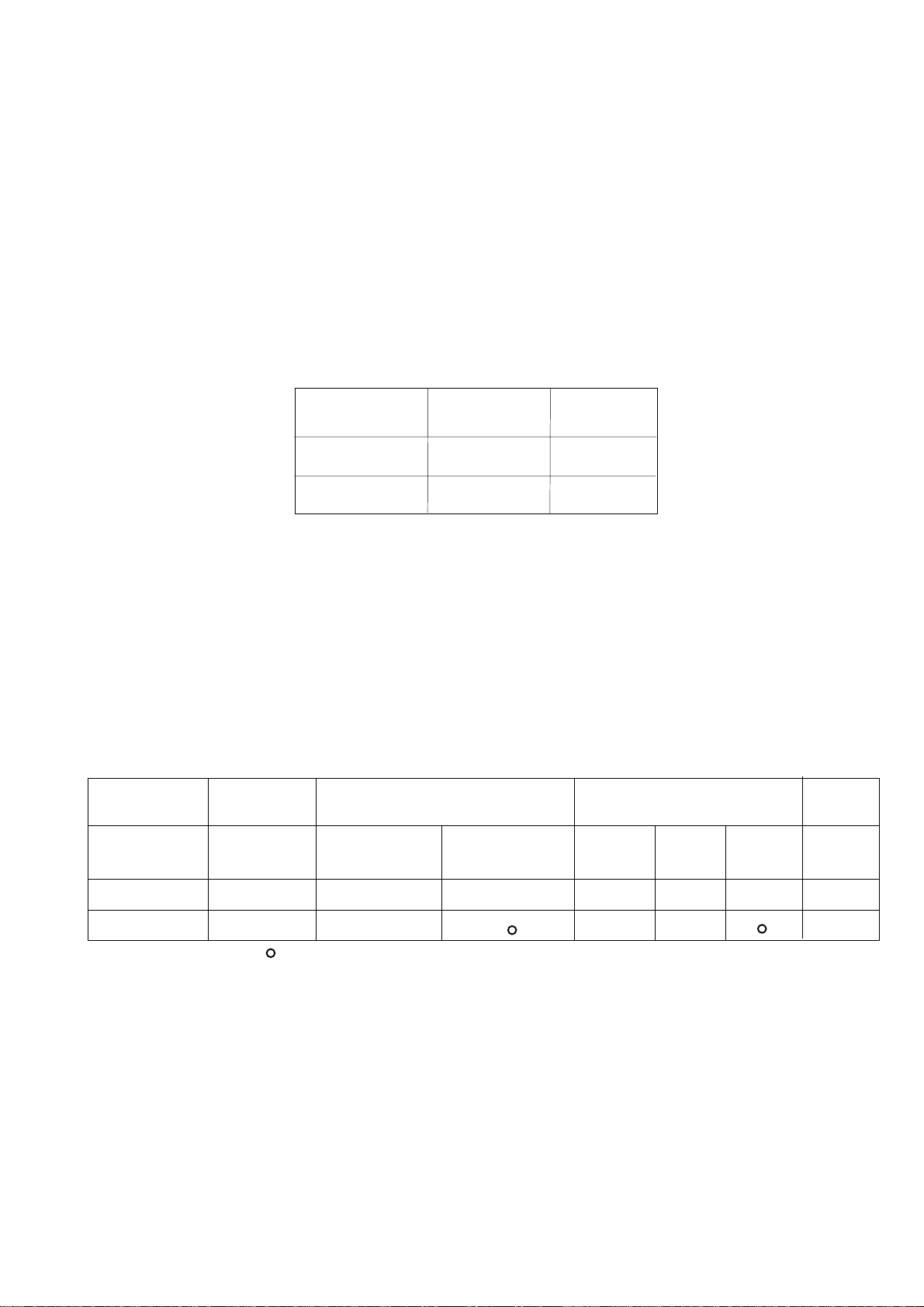
Table 1
Machine type Hook Presser foot lifting Backtacking Thread
trimmer
Class-subclass Large Via knee lever Via electro- Via hand Via Via electro-
or pedal magnet lever pedal magnet
525-101
525-105
standard equipment
•
•
•
optional equipment
•
•
•
•
•
•
•
4. Survey of equipment
This survey does not include the equipment assembled on the stand (see part B).
4.1 -for the subclass -101
4.1.1 Necessary equipment
S791 995068 Parts of backtacking (with pedal)
S791 642049 Cam for decorative stitching - standard
S791 642037 Adjusting cam – plain stitch
4.1.2 Sewing equipment
S791 124032 35 Sewing equipment 525 E 032 - standard
S791 124033 35 Sewing equipment 525 E 033
S791 124034 35 Sewing equipment 525 E 034
S791 224075 35 Sewing equipment 525 E 075
1
Page 6

4.1.3 Optional equipment
S791 149001 Attachment for serging operation
S791 235002 Unwinding device
S791 224074 Throat plate 811768 (for stitching fine materials)
S791 400023 Guiding for stitching together
S791 630002 Equipment for stitching with two needles
S791 642038 Cam for decorative stitching
S791 642039 Cam for decorative stitching
S791 642040 Cam for decorative stitching
S791 642041 Cam for decorative stitching
S791 642042 Cam for decorative stitching
S791 642043 Cam for decorative stitching
S791 642044 Cam for decorative stitching
S791 642045 Cam for decorative stitching
S791 642046 Cam for decorative stitching
S791 642047 Cam for decorative stitching
S791 642048 Cam for decorative stitching
S791 642050 Cam for decorative stitching
S791 642051 Cam for decorative stitching
S791 642052 Cam for decorative stitching
S791 642053 Cam for decorative stitching
S791 642055 Cam for decorative stitching
S791 151016 Hinged foot with front thread slit - zig-zag stitch width 6 mm
S791 151017 Hinged foot with front thread slit - zig-zag stitch width 10 mm
S791 947001 Adjustment gauges
S794 222012 Sewing lamp
S741 610118 40 High mortality spare parts kit in a plastics box
4.2 -for the subclass - 105
4.2.1 Necessary equipment
S791 995068 Parts of backtacking (with pedal)
S791 642049 Cam for decorative stitching - standard
S791 642037 Adjusting cam - plain stitch
S980 094051 Connecting cable to drive EFKA DC 1600/DA82GA and EFKA VD 552/6F82FA
4.2.2 Sewing equipment
S791 124032 35 Sewing equipment 525 E 032 - standard
S791 124033 35 Sewing equipment 525 E 033
S791 124034 35 Sewing equipment 525 E 034
S791 224075 35 Sewing equipment 525 E 075
4.2.3 Optional equipment
S791 149001 Equipment for overedging
S791 235002 Unwinding device
S791 224074 Throat plate 811768 (for stitching fine materials)
S791 400023 Guiding for stitching together
S791 630003 Equipment for stitching with two needles
S791 642038 Cam for decorative stitching
S791 642039 Cam for decorative stitching
S791 642040 Cam for decorative stitching
S791 642041 Cam for decorative stitching
S791 642042 Cam for decorative stitching
S791 642043 Cam for decorative stitching
S791 642044 Cam for decorative stitching
S791 642045 Cam for decorative stitching
S791 642046 Cam for decorative stitching
S791 642047 Cam for decorative stitching
S791 642048 Cam for decorative stitching
S791 642050 Cam for decorative stitching
S791 642051 Cam for decorative stitching
S791 642052 Cam for decorative stitching
S791 642053 Cam for decorative stitching
S791 642055 Cam for decorative stitching
2
Page 7

S791 151016 Hinged foot with front thread slit - zig-zag stitch width 6 mm
S791 151017 Hinged foot with front thread slit - zig-zag stitch width 10 mm
S791 947001 Adjustment gauges
S794 222012 Sewing lamp
S791 995153 Presser foot lift via electromagnet
S791 995154 Backtacking via electromagnet
S980 094057 Push button for backtacking EFKA DC 1600/DA82GA
S980 094060 Push button for backtacking EFKA VD 552/6F82FA
S741 610518 40 High mortality spare parts kit in a plastics box
5. Technical data
Sewing speed 4400 SPM - maximum
3500 SPM - standard
Stitch type double-thread lockstitch
Stitch length max. 5 mm
Pattern width continuously adjustable - max. 10 mm - according to the
respective accessory (cam) used
Presser foot lifting 5 mm - via hand lever
7 mm - via knee lever, pedal, electromagnet
Hook S980 008250 - horizontal, large diameter
Needle system 134 No. 90-110
Drive clutch motor 2800 RPM (min. 0,35 kW)
stop motor (min. 0,4 kW)
Head weight max. 38 kg
Stand weight 61 kg
Opening space of machine head 265 x 120 mm
Bedplate dimension 178 x 476 mm
Length of trimmed thread ends up to 20 mm
Machine power imput with clutch motor max. 700 W
Machine power imput with stop motor max. 800 W
Equivalent sound pressure level of the machine alone
at the working spot with 20 % utilization of the machine
during the working shift at the standard sewing conditions 83 dB/A
Ground plan machine dimensions (including stand) 1060 x 550 mm
Machine height (including stand and thread stand) 1490 mm
3
Page 8
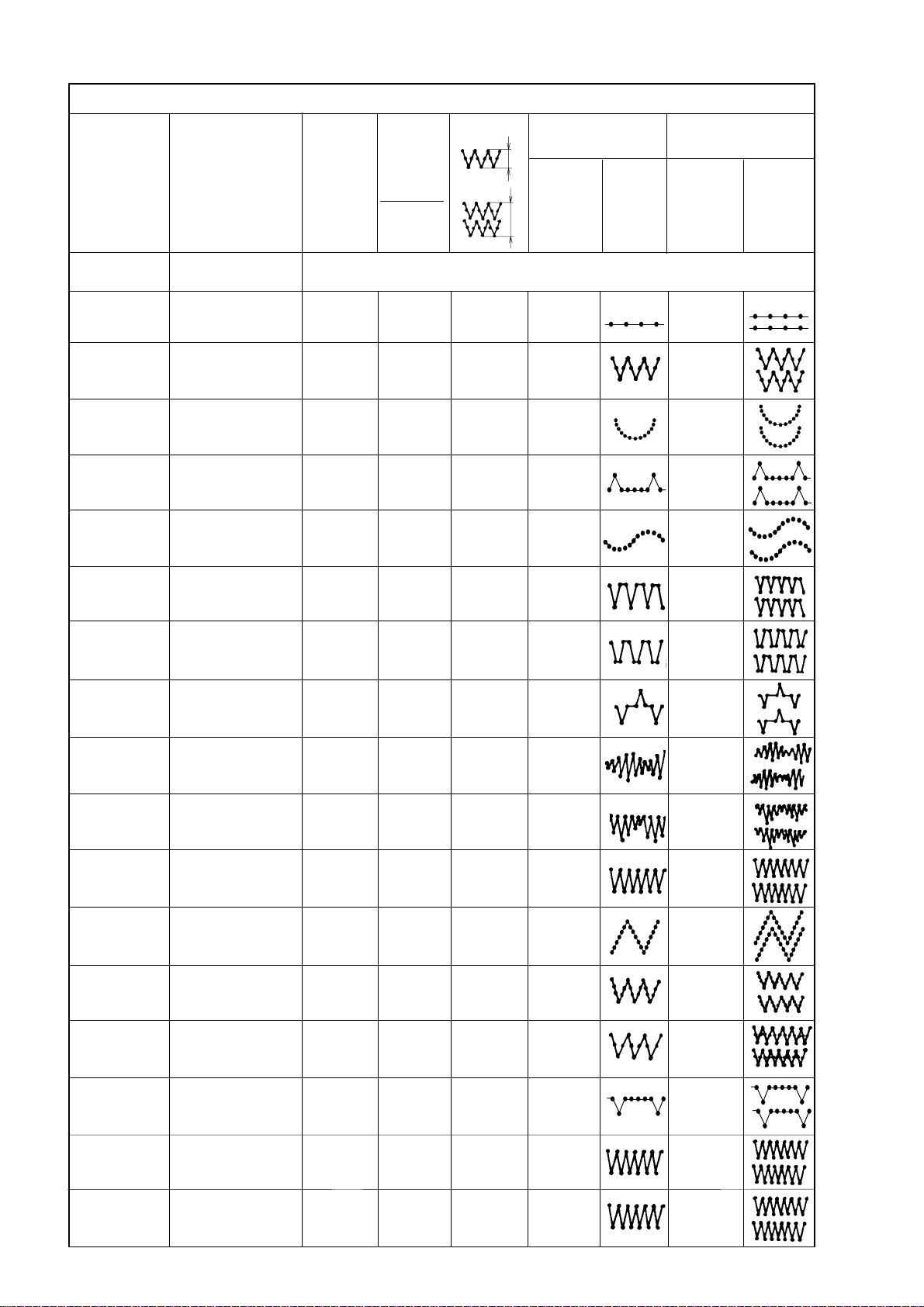
Table 2
Equipment and their method of use
Trade Ordering No Number Number Pattern width One-needle type Two-needle type
marking of needle of needle
punches/ punches/
1 rev. pattern Max. Pattern Max. Pattern
of came machine machine
Stitch speed speed
length SPM SPM
525 E 002 S791 630002 Equipment for stitching with two needles for the subclass 101 - needle distance 3; 4; 5 mm
525 E 003 S791 630003 Equipment for stitching with two needles for the subclass 105 - needle distance 3; 4; 5 mm
525 E 037 S791 642037 12 - 4400 3800
1,5-5
525 Z 038 S791 642038 12 4 4,5 - 10
1-3
525 Z 039 S791 642039 12 12 4,5 - 10 3800 3400
1-3
525 Z 040 S791 642040 12 6 3,5 - 6 3800 3400
1,5-3
525 Z 041 S791 642041 12 12 4,5 - 10 3800 3800
1,5-5
525 Z 042 S791 642042 12 3 3,5 - 6 3800 3400
1,5-4
525 Z 043 S791 642043 12 4 4 - 6 3800 3400
1-3
525 Z 044 S791 642044 12 6 4 -10 3800 3400
1-3
525 Z 045 S791 642045 12 12 2 - 5 3800 3400
1,5-3
525 Z 046 S791 642046 12 12 2 - 5 3800 3400
1,5-3
3800
3400
(
(
(
(
(
(
525 Z 047 S791 642047 12 2 3,5 - 6 3800 3400
1-3
525 Z 048 S791 642048 12 12 4,5 - 10 3800 3400
1-3
525 Z 049 S791 642049 12 6 4,5 - 10 4400 3800
1-3
525 Z 050 S791 642050 12 4 2 - 6 3800 3400
1-3
525 Z 051 S791 642051 12 6 3,5 - 6 3800 3400
1,5-3
525 Z 052 S791 642052 12 2 2 - 4,5 3800 3400
1-3
525 Z 053 S791 642053 12 2 1 - 2,4 3800 3400
1-3
4
Page 9
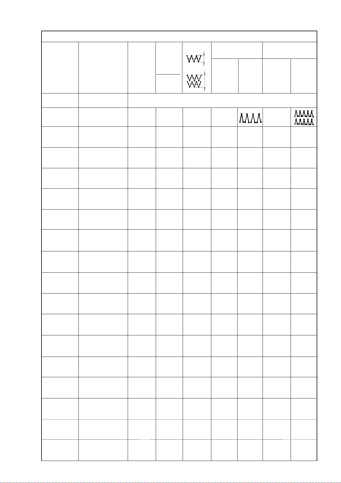
Table 2
Equipment and their method of use
Trade Ordering No Number Number Pattern width One-needle type Two-needle type
marking of needle of needle
punches/ punches/
1 rev. pattern Max. Pattern Max. Pattern
of came machine machine
Stitch speed speed
length SPM SPM
525 E 002 S791 630002 Equipment for stitching with two needles for the subclass 101 - needle distance 3; 4; 5 mm
525 E 003 S791 630003 Equipment for stitching with two needles for the subclass 105 - needle distance 3; 4; 5 mm
525 Z 055 S791 642055 12 3 3,5 - 6 3800 3400
1,5-4
5
Page 10
6. Operation of the machine
Caution!
Do not use this sewing machine without using the finger guard
(C, Fig. 4) and without the take-up lever guard (P, Fig. 2).
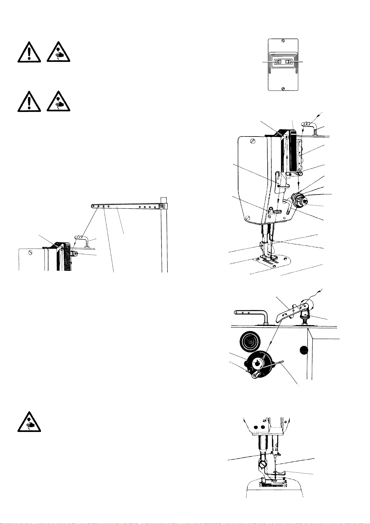
6.1 Upper thread threading (Fig. 1, 2)
Caution!
Before starting the threading operation, switch off the
main switch and put off the feet from the pedals on the
stand to avoid the starting of the machine by treading
the pedal.
After having inserted the bobbin with thread on the thread stand (N), unwind
the thread in sufficient length and pass it through the holes in the thread stand
(N). Direct it then through the thread guide (A) and through the guide (B) - with
the machines without any thread cutter, or through the auxiliary thread tensioner
(L) with the machines provided with such thread cutter. Feed the thread between
the dishes of the tensioner (C). Direct the thread through the adjusting spring
(D) around the guide (E) and through the guide (F) and (G) into the take-up lever
eye (H). From here the thread is directed downward through the guides (F) and
(J) and through the hole of the thread guide (K) on the needle bar towards the
needle eye. Thread the thread into the needle eye from the front (from the sewer)
rearward.
MAIN SWITCH
OFF ON
H
F
J
P
A
B
G
D
C
M
H
A
L
N
Fig. 1
6.2 Winding of thread on the hook bobbin (Fig. 3)
From the thread stand the thread is directed to the tensioner (A) through the
guide (B) on the machine head. From the guide the thread is directed on the
hook bobbin mounted on the shaft (C) of the winder. Wind up the thread
end several times on the bobbin in the clockwise direction and feed it towards
the spring (D). Introduce the thread between the coils thereof and, when
pulling it slightly, cut it with the knife which is mounted inside the spring.
Engage the winder by means of the lever (E). After having wound up the
thread on the bobbin, the winder stops automatically. After having removed
the bobbin from the winder shaft it is possible to cut the thread with the
knife protected by the spring (D) or to cut it with scissors. The thread (A)
serves for regulating the tension of the thread for winding.
6.3 Needle insertion (Fig. 4)
E
K
Fig. 2
B
A
C
D
E
Fig. 3
Caution!
Before starting the operation of the needle change, switch off
the main switch and put the feet off the pedals on the stand to
avoid the machine start by treading the pedal.
After having chosen the correct needle thickness (number) corresponding
to the system of the prescribed type (usually the system 134), loosen the
screw (A) in the needle holder and insert the needle (B) up to the bottom of
the hole in the needle holder. Turn it in such a way, so that its long groove is
directed ahead (towards the sewer).
Caution - when choosing a thicker needle it is necessary to check, whether
the hook beak does not catch the needle - the eventual setting of the hook
position is to be carried out by a qualified person. Check up, whether the
needle passes through the centre of the needle hole, change a faulty needle.
6
A
B
C
Fig. 4
Page 11
6.4 Adjustment of the upper thread tension
(Fig. 1, 2, 5)
The tension of the upper and that of the bottom thread must be
mutually adjusted in such a way, so that the stitch locking is being
done in the middle of the sewn material (Fig. 5). The tension of the
upper thread is to be adjusted by turning a bit the nut of the tensioner
(M, Fig. 2). In turning the nut to the right (in the clockwise direction),
we increase the tension of the upper thread, in turning it in the
opposite direction, we reduce the tension of the thread.
When the machine is provided with a thread cutter of thread (version
-105), its correct function is to be given major attention in adjusting
correctly the thread tension. It is necessary to set correctly the
auxiliary tensioner (L, Fig. 1) the function of which influences the
length of the upper thread end which is projecting from the needle
eye after having cut the thread. When correctly setting of the tensioner, the quality of the initial stitches is good and no unthreading of
the thread out from the needle occurs. When increasing the adjusted
tension of the auxiliary tensioner this end is shorter (the seam
starts are of better quality), but there is an increased danger that this length will not be sufficient for starting further stitching,
when the thread would leave the needle eye. In the opposite case, namely with a too small tension, the given ends are uselessly
too long which worsens the quality of the stitch start on the rear side of the sewn material.
Correct adjustment
of the tension of both
threads
Incorrect adjustment
Incorrect adjustment
Fig. 5
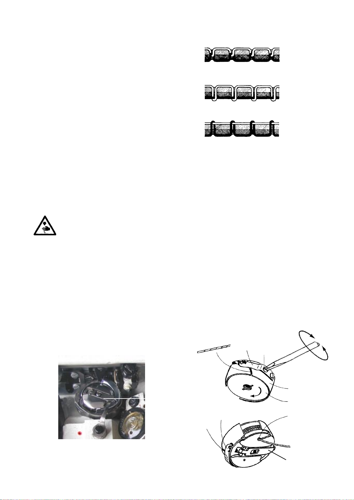
6.5 Change of the hook bobbin, threading and setting of the bottom thread tension (Fig. 6, 7)
Caution!
Do not start the machine before placing the hook covers in their working (protective) position.
Before changing the bobbin in the hook, switch off the main switch and put your feet off the pedals on the stand to
avoid the machine start by treading the pedal.
Using the flap (F), remove the bobbin case from the hook.
Put the full bobbin (A) into the bobbin case (B) and guide the thread through the groove (C) under the braking spring (D) and then
into the hole (E).
Let free about 5 – 6 cm of the thread end. It is recommended to turn the bobbin in the arrow direction when pulling the thread.
After having inserted the bobbin case into the hook be sure in assuring this by the flap (F). As usual, by means of the the upper
thread, we thread the bottom thread above the throat plate.
The tension of the bootom thread is regulated by a screw (G). In turning it in the (+) direction, the pulling power increases, in the
(-) direction it is reduced. When the tension of the bottom thread is correctly adjusted, then a good stitch laying is generally being
ensured by the respective adjustment of the upper thread tension by means of the tensioner nut.
+
C
F
D
G
B
A
-
Fig. 6
D
C
E
F
Fig. 7
7
Page 12
6.6 Adjustment of the stitch length, reverse stitching (Fig. 8, 9)
The stitch length is changed in turning the knob (A), which is placed on the arm web, according to the numbers indicating the
stitch length against the symbol (B) on the machine arm. In turning the knob in the direction of the arrows, the stitch length is
increased (+) or reduced (-).
The direction change of feeding the stitched material is mechanically controlled by the reversible stitch lever (C) in pushing it in
the direction of the arrow (S).
According to the chosen accessory, the machine can be provided with an electromagnetic backtacking control (see Part B, par.
8) or with a control by a backward stitch pedal (P).
+
-
B
A
C
S
Fig. 8a
P
Fig. 8b
6.7 Adjustment of the pattern width (Fig. 9)
Caution! Danger of injury!
Switch off the main switch! Before starting the setting operation,
wait until the motor stops!
Before any pattern width change. it is necessary to stop the machine with
the needle in its top position. According to the table 2, mount the cam for
the desired pattern and the pattern width is to be set in such a way, so that
it suits the interval of the respective cam indicated in the table 2. The
pattern width is continuously adjustable. Setting is to be done after having
removed the guard on the machine arm on the lever (E) which controls the
movement of the needlebar holder. Using a key, loosen the nut (G) on the
screw (H), on which the draw bar from the needlebar holder is mounted.
When shifting the screw in the slot of the lever (E) downwards, the pattern
is being narrowed, in shifting it upwards, the stitched pattern is widened.
When setting the maximum width of the patern, check the needle to avoid
its striking into the throat plate. Lock the set up position with the nut (G).
When using the accessory for sewing with two needles, the pattern width
is to be set in such a way, so that the needles pass with sufficient clearance
within the needle groove of the throat plate.
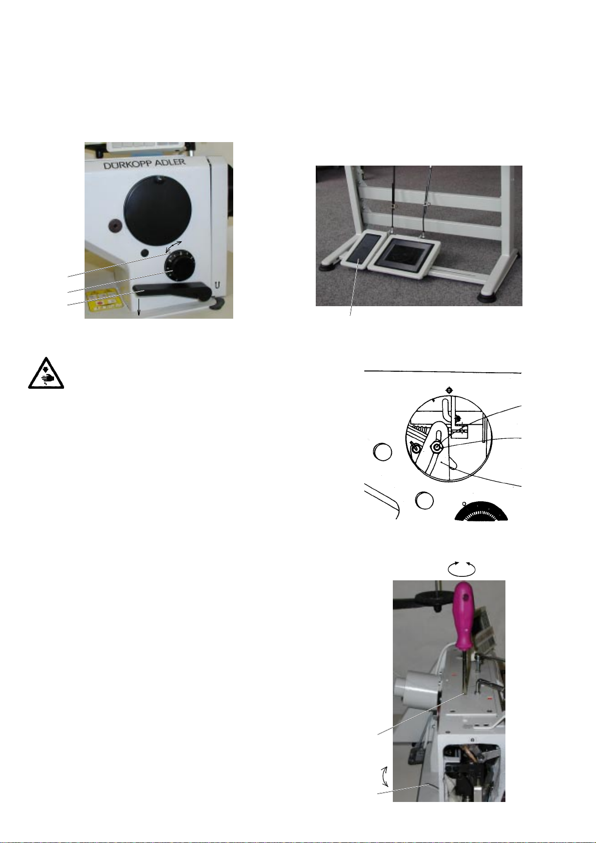
6.8 Regulation of the presser foot pressure,
presser foot lifting (Fig. 10)
H
G
E
Fig.9
+-
The pressure of the presser foot is regulated using an adjusting screw in the
hole (A) which is placed below the top cover of the machine arm and is accessible
from above through the hole in this cover. In turning the adjusting screw in
the direction of the arrows we increase (+) or reduce (-) the pressure of the
presser foot. The pressure of the presser foot must be sufficient for ensuring
a reliable and continuous feeding of the sewn materila with the maximum
sewing speed. A correct adjustment of the pressure of the pressure bar
influences, whether the sewn material is being continuously fed without any
damage and whether the stitch length is uniform.
The mechanical lifting of the presser foot is enabled by means of the hand
lever (B) which when lifted arrests the presser foot in its top position. The
presser foot can be lifted with the knee lever or with the left pedal too according to the machine subclass.
The assembling procedure of the automatic presser foot lifting using
electromagnet is described in the part B, par. 7.
8
A
B
Fig. 10
Page 13

7. Machine maintenance
Caution!
Before cleaning and lubricating the machine switch off the main switch and put your your feet off the pedals on the
stand to avoid starting the machine by treading the pedal.
7.1 Cleaning
Maintain the machine clean and at least once a day (according to the processed material) remove dirt from the hook and feeder
space by means of a brush, with the machines provided with a thread cutter, from the cutting space as well. Avoid using volati le
liquids for cleaning purposes, they damage the machine and the health too. Check up the filtering sieve on the electric motor for
not being choked with dust.
7.2 Lubrication (Fig. 11, 12, 13)
For lubricating the machine use Esso SP-NK 10 oil or another oil of the same quality (viscosity at 40° C: 10 mm2/s; inflammation
point: 150°C). Before starting the stitching operation, put one oil drop into the holes marked with red colour on the machine
(Fig. 12, 13). Check up specially the oil level on the oil level gauge (1) for lubricating the hook. Refill oil through the hole (2) above
the oil level gauge only when the oil lever considerably sinks below the middle of the oil level gauge.
From time to time, oil is to be dropped into the hole of the hook gearbox (Fig. 13). The quantity of the oil fed for lubricating the
hook is regulated by turning a bit a regulation pin (3) using a screwdriver within the extent of 0 - MAX, that is to the left, in
counterclockwise direction. The pin is placed on the front side of the oil vessel under the bedplate. When setting the indicator
of the regulation pin on “0”, the minimum oil feeding to the hook is ensured, so that its seizure is avoided. After having put the
machine into operation, check and refill regularly the oil level in the oil vessel at the hook and in the oil vessel on the machine arm.
It is necessary to refill ESSO BEACON EP2 grease in the shafts of the feeding mechanism (4, 5).
4
5
Fig. 11
12
3
Fig. 13Fig. 12
9
Page 14

-1 -2
0
1 ÷ 13
Fig. 14
8. Electronic control of the machine
(it is valid for sub-classes equipped with stop motor)
8.1 Control of sewing by means of control elements
8.1.1 Via treadle (treadle positions and function
possibilities) (Fig. 14)
The position of the treadle is read by the reader, which can
recognise 16 levels. Its meaning is shown on the table and
see Fig. 14.
Treadle Treadle Meaning
position
Foot full backwards Command for thread
-2
-1
0 Neutral position Note
1
2
3
: : :
13
Foot slightly Commandlifting
Slightly forwards Command releasing
Continually Sewing at minimum
forwards speed (1. gear)
Continually Sewing at second
forwards speed level
Fully forwards Sewing at maximum
trimming (seam finishing)
the foot up
foot
speed (12. gear)
1
Fig. 15
Note: It is possible to pre-adjust the needle position (up/down)
and foot position (up/down) by stopping in seam (introducing the treadle in neutral position). Foot position (up/down)
after seam finishing (pressing the treadle by foot fully backwards).
8.1.2 Via pushbutton (Fig. 15)
The pushbutton has got a firmly set function of bar operation
(when depressing the push button during the sewing operation, the sewn material is being reverse fed).
8.1.3 Via control panel Efka V 810/V 820
(Fig. 16, 17)
These functions are standardly assigned to the pushbuttons
A, B:
A - cancelling (recalling) the bar
B - needle up/down
Note: Function of the A,B pushbuttons can be changed by
different adjustment of parameters 293,294 (see original
operating instruction Efka DA82GA).
10
Page 15

Fig. 16
8.2 Adjustment of automatic functions via control
panel for stop motor
8.2.1 By using stop motor Efka with panel V 810
(Fig 16)
Functioning pushbuttons engagement:
Pushbutton P Recalling and program mode termination
Pushbutton E Confirmation of program mode changes
Pushbutton + Increase of value displayed in program
mode
Pushbutton - Decreasing value displayed in program
mode
Pushbutton 1 Start bar SINGLE/DOUBLE/OFF
Pushbutton 2 End bar SINGLE/DOUBLE/OFF
Pushbutton 3 Automatic foot lifting after stopping at
the seam ON/OFF
Automatic foot lifting after thread trim-
ming (end of seam) ON/OFF
Pushbutton 4 Basic position of needle UP/DOWN
Pushbutton A For cancelling respectively recalling
the bar
Pushbutton B For switch over the needle position
UP/DOWN respective shift pushbutton
in program mode
Symbol C Connection of automatic revolutions
Symbol D Connection of lighting barrier
Symbol E The machine is running
Symbol F The revolutions limitation switch on
Symbol G Connection of lower thread controller,
flashing light indicator symbol when
the threads supply on the bobbin is
running out
The arrows on the display indicate switching the functions
which are displayed by symbols above the pushbuttons on.
8.2.1.1 Adjustment by means of buttons with fixed setting
function (Fig. 16)
Note: It is important to finish the seam in order to reach
effective button pressing (press the treadle fully backwards
down).
Setting start bar:
Drive enables sewing start bar automatically. It is necessary to
choose the type (single, double, off) and number of stitches
which will be sewn forwards and backwards.
The arrow above its symbol shows the type of bar (chosen by
gradually pressing pushbutton 1). It will be displayed following after pressing pushbutton 1.
Arv (SAv) XXX - number of stitches of start (fancy) bar forwards or
Arr (SAr) XXX - number of stitches of start (fancy) bar backwards) for about 3 sec.
At this time you can change the number of stitches by gradually pressing the pushbutton + or -.
Setting end bar:
The same applies to the start bar (setting by the means of
pushbutton 2).
Erv (SEv) XXX - end (fancy) bar number of stitches forwards
Err (SEr) XXX - end (fancy) bar number of stitches backwards
11
Page 16

Foot position adjustment by stopping at the seam (by neutral
position of treadle) and after finishing seam (by neutral position of treadle):
Setting is by means of pushbutton 3, arrow indication above
the corresponding symbol.
Needle position adjustment by stopping at the seam:
Setting is by means of pushbutton 4.
8.2.1.2 Setting by means of parameters (Fig. 16)
Drive memory contains the parameters which enables sewing
system tuning. These parameters have exact meaning and
they are divided into 3 levels. Further parameters which are
available only for operation will be quoted. Each parameter
has its (sequence) number and value.
General procedure by changing parameters of operation level:
- switch the main switch on or finish the seam by pressing the
treadle fully backwards down
- press pushbutton P on the panel V 810
- it will be displayed on the display F 000 (000 it is the number
of parameter)
- by several times pressing + (or -) set the requested number
of parameter
- push pushbutton E down and it will be shown the value of
parameter on the display
- you can change the value by means of pushbutton + or –
- by pushing pushbutton E down you will change the sequence
to the following number of parameter
- by pushing pushbutton P down you will leave the mode of
changing parameters
Note: 1. For permanent memory storing of changed pa-
rameter, it is necessary to press treadle forwards
down after changing of parameters.
2. Mode of changing parameters is possible only after finishing of the seam.
Number of stitches in bars:
Number of stitches is stored in parameter’s number.
No. of parameter Value range Description
of parameter of parameters
000(080) 0-254
001(081) 0-254
002(082) 0-254
003(083) 0-254
Sewing according to sewing program:
Drive with panel V810 automatically enables sewing of 1 seam
with setting number of stitches. It is necessary to set in corresponding number of stitches, and initialisation of sewing program.
Number of stitches of
start (fancy) bar forwards
Number of stitches of
start (fancy)bar backwards
Number of stitches of
end (fancy) bar backwards
Number of stitches of
end (fancy)bar forwards
No. of parameter Value range Description
of parameter of parameters
007 0-254 Number of stitches
015 ON/OFF
12
ON/OFF sewing under
sewing program
Page 17

ON/OFF thread trimmer:
No. of parameter Value range Description
of parameter of parameters
013 ON/OFF
Thread trimmer
ON/OFF
CD E F GHI JKLMNOPQ
AB
Fig. 17
8.2.2 By using stop motor Efka with panel V 820
(Fig. 17)
Functioning pushbuttons engagement:
Pushbutton P Call and termination of programming mode
Pushbutton E Confirmation when changing programming
mode
Pushbutton + Increasing the value displayed in program-
mingmode
Pushbutton - Reducing the value displayed in program-
ming mode
Pushbutton 1 Start bar SINGLE/DOUBLE/OFF
Pushbutton 2 Stitch counting FORWARD/BACK/OFF
Pushbutton 3 Light barrier function
LIGHT-DARK/DARK-LIGHT/OFF
Pushbutton 4 End bar
SINGLE/DOUBLE/OFF
Pushbutton 5 Function
TRIMMING/TRIMMING+EJECTOR/OFF
Pushbutton 6 Automatic foot lifting after having stopped
inside the seam ON/OFF
Automatic foot lifting after trimming ON/
OFF
Pushbutton 7 Basic needle position UP/DOWN
Pushbutton 8 Lower thread waste controlling ON/OFF
Pushbutton 9 Operation pushbutton - programmable
Pushbutton 0 Programming/processing of 40 possible
sewing sections (seams)
Pushbutton A For cancelling or calling the bar
Pushbutton B For switching needle position UP/DOWN,
resp. shifting pushbutton in the program-
ming mode
Symbol C Designating symbol C for code number
Symbol D Designating symbol F for parameter
number
Symbol E Programme number in TEACH IN mode
Symbol F Seam number in TEACH IN mode
Symbol G Run blocking ON
Symbol H Blocked insertion by pushbutton
Symbol I Fault reporting
Symbol J Insertion of stitch number in TEACH IN
mode
Symbol K Connected lower thread controller, flash-
ing symbol when running out thread re-
serve on bobbin
Symbol L Limitation of revolutions ON
Symbol M Right needle disconnected
symbol N Evening stitches for light barriee in the
TEACH IN mode
Symbol O Machine is running
Symbol P Automatic revolutions ON
Symbol Q Left needle disconnected
The arrows on the display indicate switching the functions
which are displayed by symbols above the pushbuttons on.
13
Page 18

8.2.2.1 Adjustment by means of buttons with fixed setting
function (Fig. 17)
Note: It is important to finish the seam in order to reach
effective button pressing (press the treadle fully backwards
down).
Setting start bar:
Drive enables sewing start bar automatically. It is necessary to
choose the type (single, double, off) and number of stitches
which will be sewn forwards and backwards.
The arrow above its symbol shows the type of bar (chosen by
gradually pressing pushbutton 1). It will be displayed following after pressing pushbutton 1.
Arv (SAv) XXX - number of stitches of start (fancy) bar forwards or
Arr (SAr) XXX - number of stitches of start (fancy) bar backwards for about 3 sec.
At this time you can change the number of stitches by gradually pressing the pushbutton + or -.
Setting end bar:
The same applies to the start bar (setting by the means of
pushbutton 2).
Erv (SEv) XXX - end (fancy) bar number of stitches forwards
Err (SEr) XXX - end (fancy) bar number of stitches backwards
Note: The last section of end bar must have at least 3 stitches.
Foot position adjustment by stopping at the seam (by neutral
position of treadle) and after finishing seam (by neutral position of treadle):
Setting is by means of pushbutton 6, arrow indication above
the corresponding symbol.
Needle position adjustment by stopping at the seam:
Setting is by means of pushbutton 7.
Trimming switched ON/OFF:
To be set using pushbutton 5.
Sewing programme ON:
To be switched on using pushbutton 0.
Switching ON/OFF the function of the pushbutton F:
The pushbutton F on panel can have assigned one of the
following functions: Sst - softstart
SrS - fancy bar
Frd - reverse angle after trimming
8.2.2.2 Setting by means of parameters (Fig. 17)
Drive memory contains the parameters which enables sewing
system tuning. These parameters have exact meaning and
they are divided into 3 levels. Further parameters which are
available only for operation will be quoted. Each parameter
has its (sequence) number and value.
General procedure by changing parameters of operation level:
- switch the main switch on or finish the seam by pressing the
treadle fully backwards down
- press pushbutton P on the panel V 820
- on the display there is no data shown
- by depressing the pushbutton E several times, set the
required parameter (without having displayed the parameter
number)
- you can change the value using pushbuttons + or -
- by depressing the pushbutton E you will pass in the given
sequence to the following parameter
- by depressing the pushbutton P down you will leave the
mode of changing parameters
14
Page 19

Note: 1. For permanent memory storing of changed pa-
rameter, it is necessary to press treadle forwards
down after changing of parameters.
2. Mode of changing parameters is possible only after finishing of the seam.
Number of stitches in bars:
Number of stitches is stored in parameter’s number.
No. of parameter Value range Description
of parameter of parameters
000(080) 0-254
001(081) 0-254
002(082) 0-254
003(083) 0-254
The drive with the panel V 820 enables sewing automatically
up to 40 seams distributed up into eight programmes with the
given stitch numbers and sewing direction (forwards/rearwards). For more detailed information see the original driving
instructions.
Number of stitches of
start (fancy) bar forwards
Number of stitches of
start (fancy) bar backwards
Number of stitches of
end (fancy) bar backwards
Number of stitches of
end (fancy) bar forwards
15
Page 20

Operating instructions for eventual trouble shooting
Note: When the machine is driven by a stop motor, it is indispensable to check up, before starting its repair, the setting of its
parameters according to Instructions for assembling, part B, par. 12.5.2.
Trouble
1. Machine runs with difficulty.
2. Machine starts with slow running.
3. Upper thread tearing.
Cause
1.1 Machine out of use for certain time,
dried oil and dirt in bearings.
2.1 Insufficient tension of the belt from
electic motor.
3.1 Thread guides incised.
3.2 Sharp hook point.
3.3 Bad feeding.
3.4 Incorrect guiding or upper thread
threading.
3.5 Excessive thread tension.
3.6 Needle incorrectly mounted or damaged.
3.7 Thread thickness does not anwer
the thickness of sewn material.
3.8 Machine excessively dirty.
3.9 Thread wound up on the hook.
Method of troubleshooting
Inject some drops of kerosene into all
oiling holes and on sliding surfaces and
put the machine in quick running to clean
out the oiling holes in the bearings. Lubricate then the machine with oil for sewing machines according to par. 7, part A.
Tension the belt according to par. 5.1.2,
part B.
Check up and replace the guides.
Repair.
Set tension according par. 3; 6; 7, part C.
Thread upper thread according to par.
6.1, part A.
Set tension according par. 6.4, part A.
Replace needle according to par. 6.3,
part A.
Use more suitable thread.
Unscrew throat plate and clean out te
machanism. Remount the throat plate
according to the par. 5, part C.
Remove thread.
4. Lower thread tearing.
5. Skipping of stitches.
6. Needle breaking.
3.10 Thread too thin or insufficiently resistant.
4.1 Incorrect threading of the thread
in the bobbin case.
4.2 Thread too weak or insufficiently
resistant.
4.3 Thread incorrectly wound up on the
hook bobbin.
4.4 Bobbin damaged.
4.5 Sharp pressure spring on the bobbin case.
5.1 Needle incorrectly mounted.
5.2 Needle blunt or bent.
5.3 Hook point incised or broken.
5.4 Big needle hole in throat plate.
5.5 Broken adjusting spring for tensioning upper thread.
5.6 Needle bar too high or too low.
5.7 Hook overrun, incorrect timing adjustment.
5.8 Dirty hook mechanismus.
6.1 Feeder too high.
6.2 Negligent sewing, pulling of the
material.
Use a more suitable thread.
Thread correctly the thread according to
par.. 6.5, part A.
Use a more suitable thread.
Rewind the bobbin.
Replace bobbin.
Replace spring.
Insert correctly needle according par. 6.3,
part A.
Replace needle accordingd to par. 6.3,
part A.
Replace hook.
Replace throat plate and mount it according to par. 5, part C.
Replace spring and set upper thread tension according to par. 6.4, part A.
Set according to par. 10, part C.
Adjust hook timing according to par. 11,
part C.
Clean out with kerosene and lubricate
with oil.
Set the feeder height according to par. 3,
part C.
Let material pass freely.
16
Page 21

6.3 Needle too thin for thick material.
6.4 Needle incorrectly mounted.
6.5 Throat plate loosened.
6.6 Upper thread tension too high.
Replace needle according to par. 6.3,
part A.
Mount correctly needle according to par.
6.3, part A.
Mount throat plate according to par. 5,
part C.
Set tension according to par. 6.4, part A.
7. Difficult and uneven machine feeding.
8. Incorrect stitch locking. Threads
locked on the top side of sewn material.
9. Incorrect stitch locking. Threads
locked on the bottom side of sewn
material.
7.1 Feeder too low.
7.2 Feeder used.
7.3 Feeder teeth fouled or blunt.
7.4 Insufficient presser foot pressure.
8.1 Incised spring on bobbin case,
lower thread insufficiently braked.
8.2 Lower thread not threaded under
bobbin case spring.
8.3 Lower thread retained under the
bobbin case spring.
8.4 Unequal setting of upper and lower
thread tension.
8.5 Machine feeds too soon.
9.1 Tensioning disks incised by upper
thread.
9.2 Thread does not pass around hook
or is retained by the bobbin case.
9.3 Upper thread not threaded between
the tensioning disks.
9.4 Lower thread retained between the
tensioning disks.
9.5 Unequal setting of upper and lower
thread tension.
Set the feeder height according par. 3,
part C.
Replace.
Clean or replace feeder.
Increase pressure according to par. 6.8,
part A.
Replace spring.
Rethread thread according to par. 6.5,
part A.
Clean.
Set thread tension according to par. 6.4
and 6.5, part A.
Set feeding according to par. 3; 6; 7,
part C.
Replace disks and set upper thread tension according to par. 6.4 and 6.5, part A.
Clean hook and set up bobbin case.
Thread correctly the thread according to
par. 6.1, part A.
Clean thread tensioner and set it according. 6.4, part A.
Set correctly according to par. 6.4,
part A.
10. Hook blocked.
11. Little reserve of upper thread, machine does not start sewing, upper
thread leaves needle eye at the start
of next sewing.
12. Little reserve of lower thread, machine does not start sewing.
13. Thread ends untrimming or insufficiently trimming.
10.1 Lower thread wastes retained in
hook.
11.1 Excessive tension of auxiliary tensioner.
11.2 Cam time setting too quick.
11.3 Machine stops before upper dead
center.
11.4 Electromagnet loosening main
tensioner is out of function.
11.5 Incorrect upper thread unwinding.
12.1 Lower thread end drawn into bobbin case.
12.2 Excessive winding up speed.
12.3 Excessive lower thread tension.
12.4 Burr on the covering hook sheet.
13.1 Incorrectly set up (little) pressure
of fixed knife.
13.2 Blunt fixed or trimming knife.
Move hand wheel in spite of considerable resistance in both senses until the
threads in the hook get cut up. After having removed them, let run the machine
unthreaded a while and then lubricate the
hook with 2-3 drops of oil recommended
in the par. 7, part A.
Reduce tension according to par. 6.1,
part A.
Delay according to par. 22, part C.
Set according 28, part C.
Find out the cause and repair.
Repair.
Increase lower thread winding up tension
according to par. 6.2, part A.
Maintain maximum number of revolutions 140/min.
Reduce according to par. 6.5, part A.
Polish up.
Set according to par. 27, part C.
Replace or sharpen.
17
Page 22

14. Low quality of stitch start on rear
side.
14.1 Upper thread end too long.
Increase tension of auxiliary tensioner
according to par. 6.1, part A.
Adjust time setting of cam according to
22, part C.
15. No upper or lower thread trimming.
16. No upper and lower thread trimming, but machine rotates from
lower to top position.
17. Machine starts sewing only after
having skipped some stitches.
18. When starting sewing operation,
upper thread end projects above the
sewn material.
15.1 Incorrect cam time setting.
15.2 Skipped stitches with slow machine revolutions.
15.3 Incorrect thread division with trimming knife.
15.4 Low lifting of trimming knife.
16.1 Incorrect cam time setting.
16.2 Incorrect function of electromagnet for trimming control (it gets
seized).
16.3 Insufficient trimming knife lifting.
17.1 Insufficient upper thread reserve.
17.2 Insufficient lower thread reserve.
18.1 Upper thread reserve too big.
Set correctly cam according to par. 22,
part C.
Set up.
Set or replace trimming knife according
to par. 26; 31, part C.
Set up according to par. 26, part C.
Set cam correctly according to par. 22,
part C.
Check up connection-replace eventually
electromagnet.
Set up according to par. 23, part C.
Set up according to par. 6.1, part A; par.
22 and 28, part C.
Polish up trimming knife and hook.
Increase tension of auxiliary tensioner
according 6.1, part A.
Change cam time setting according 22,
part C.
Adjust machine stopping with needle bar
in top dead centre according par. 28,
part C.
18
Page 23

Contents - part B - The instructions for assembling:
1. Safety instructions ............................................................................................................................................................ 1
2. Method of delivering the machine ................................................................................................................................. 1
2.1 Complete head with accessories ........................................................................................................................... 1
2.2 Stand ........................................................................................................................................................................ 1
2.3 Motor ........................................................................................................................................................................ 1
2.4 Motor pulley ............................................................................................................................................................ 2
3. Stand table top ................................................................................................................................................................... 2
4. Assembly of the stand frame and height setting ......................................................................................................... 2
5. Assembly and screwing on of the stand table top ....................................................................................................... 5
5.1 Assembly of stand table top .................................................................................................................................. 5
5.1.1 Placing of the machine head on the stand ................................................................................................ 5
5.1.2 Assembly of motor pulley, belt, belt covers ............................................................................................... 5
6. Mounting of a position reader and of a control panel of the stop motor ................................................................. 6
7. Mounting of the equipment for presser foot lifting using electromagnet ............................................................... 6
8. Mounting of the equipment for backward stitching..................................................................................................... 7
9. Mounting of the lighting .................................................................................................................................................. 7
10. Composition and assembly ot the thread stand ........................................................................................................... 8
11. Preparation of the machine for sewing .......................................................................................................................... 8
12. Instructions for putting the electronically controlled drive into operation ............................................................ 9
12.1 Power supply 1 x 230 V - DC motor ...................................................................................................................... 9
12.2 Power supply 3 x 400 V - five wire power distribution, power supply 3 x 230 V - four wire or
five wire power distribution ................................................................................................................................... 1 0
12.3 Power supply 3 x 400 V - four wire power distribution plus 1 x 230 V - two wire cable ................................. 1 0
12.4 Electrical connection of machine head to the stop motor ................................................................................. 1 1
12.5 Stop motor setting S359 600045 XXX - EFKA DC 1600/DA82GA ...................................................................... 1 3
12.5.1 Setting position reader .............................................................................................................................. 1 3
12.5.2 Changes of setting parameters of stop motor setting considering original producer ssetting ........ 1 3
12.6 Stop motor setting S359 600052 XX - EFKA VD 552/6F82FA ............................................................................ 13
12.6.1 Setting position reader .............................................................................................................................. 1 3
12.6.2 Changes of setting parameters of stop motor setting considering original producer setting .......... 1 4
Page 24

Part B - Instructions for assembling
1. Safety instructions
Caution!
The assembly of the machine is to be done only by a trained mechanician.
All operations connected with the electric installation of this sewing machine are to be done only by an authorized
electromechanician. It is absolutely necessary to get acquainted with the instructions concerning the drive supplied
by the manufacturer thereof.
2. Method of delivering the machine
The content of the delivery is given by the agreement between the supplier and the buyer. There are the following possibilities:
2.1 Complete head with accessories
In this case the delivery contains:
- Complete head.
- Selected spare parts.
- Standard accessories (containing tools see catalogue of spare parts).
- Special accessories (containing some components of the stand - see catalogue of spare parts).
2.2 Stand
The delivery contains components of the stand, but without the stand components contained in the special accessories
delivered with the machine head (see par. 2. 1) and without any electric components.
When not otherwise agreed, the stand will be delivered in disassembled state. When an assembled stand is required, then
special accessories from the head delivery will be used.
Stand complete (ordered number S072 500100 for subclasses -101 and -105) contains following items:
MG53 000501 Stand frame
MG53 002501 Big pedal
MG53 007511 Set of parts for stand
S615 000316 Stand table top
Equipments for stand (it has to be ordered separately):
Presser foot lifting by pedal:
S522 000450 Small pedal
S980 044982 Presser foot lifting draw bar
Reverse stitching:
S522 000450 Small pedal
S980 060028 Reverse stitching draw bar
2.3 Motor
The delivery contains the proper motor, switch - circuit breaker, complete cabling (except of the plug) and connecting
material. According to the motor type, it may contain a control panel. When not otherwise agreed, it is delivered in
disassembled state. The machine without thread cutting device is provided with a clutch motor with lever. When positioning
or presser foot lifting or backward stitching with electromagnet are required, the machine without thread cutting device
must be provided with a stop motor.
1
Page 25

Motors are to be chosen according to the following table:
Machine Ordered Name ø of pulley Machine rev. Approx. specification
subclass number mm max./min
S359 600030 88 FIR 1148 88 3800 asynchronous
101 S359 600030 75 3 x 400/230 V, 50/60 Hz 75 3200 switch-circuit breaker with cabling
S359 600030 58 58 2500 connection material
S359 600045 810 Stopmotor EFKA 58 adjustable D-C motor (A-C servo); switch-circuit breaker
S359 600045 820 DC 1600/DA82GA 58 adjustable control panel EFKA V 810/V820
1 x 230 V, 50/60 Hz connection material and cabling
105 S359 600052 88 Stopmotor EFKA 88 3800 asynchronous
S359 600052 75 VD 552/6F82FA 75 3200 clutch and brake
S359 600052 58 3 x 400/230 V, 50/60 Hz 58 2500 switch-circuit breaker with cabling
connection material
control panel EFKA V 810/V820 *
bipolar clutch motor
bipolar stopmotor with friction
* Control panel S359 600038/V810 or S359 600050/V820 it is possible to order for setting the stop motor, however, it is
not included in supply of the stopmotor and it has to be ordered separately.
The given stop motors have been tested on the machine and comply with the functional requirements. Other types of
stop motors may or may not have suitable parameters.The manufacturer thereof does not recommend any use of
different stop motor without having tested it.
2.4 Motor pulley
By stopmotor EFKA DC 1600/DA82GA is revolutions are set continuously by electronics.
The pulley for the maximum or other sewing speed will be supplied on express wish of the customer.
The pulley are to be chosen according to the following table:
Motor Sewing speed Sewing speed ø of pulley Ordered number
50 Hz 60 Hz mm of pulley
FIR 1148/552/3 1810 2170 42 S980 045548
EFKA VD552 2020 2430 47 S980 045377
2150 2580 50 S980 045491
2330 2790 54 S980 045361
2500 3000 58 S980 045472
2710 3260 63 S980 045378
2890 3460 67 S980 045476
3020 3620 70 S980 045370
3230 3880 75 S980 045384
3450 4140 80 S980 045479
3660 4400 85 S980 045480
3790 - 88 S980 045383
3880 - 90 S980 045481
4310 - 100 S980 045483
2
B = 100 mm
A = 80 mm
Fig. 1
3. Stand table top
For the event when the customer will ensure his own stand
table top, its drawing is given on the page 4 (Fig. 5).
4. Assembly of the stand frame and height setting
2
(Fig. 1)
Proceed to the assembly of the stand frame according to
the Fig. 1. The dimension “B” is destined for a middle-
1
high stature of the machine attending person. For a higher
stature it is necessary to increase the dimension “B” and
inversely. The machine feet are to be levelled with the
floor in loosening the screws (1). Using the screws (2) it
is possible to set up the height of the stand table top.
2
Page 26

Fig. 4
Fig. 2
A
16
5
4
5
B
1
3
Fig. 3
200
70
8
6
13
2
7
3
Page 27

3
G
2
G
Fig. 5
4
Page 28

5. Assembly and screwing on of the stand table top
5.1 Assembly of stand table top (Fig. 2, 3, 4, 5)
Put the rubber inserts for placing the machine head into the stand table top into the recess (2 and 3, Fig. 5). For better
fastening, we recomment to stick on the inserts. When mounting the tray (1, Fig. 2) be sure in maintaining the distance “X”
on the whole perimeter of the tray between the interior of the tray and the perimeter of the stand table top recesss (2).
Screw on the main switch (4) on the stand table top (2, Fig. 3).
Fasten the rubber bumper (3, Fig. 3).
Screw on the motor holder (5) according to the Fig. 3 and 4.
Screw on the lighting transformer (6, Fig. 3) for the lighting – if delivered.
Install electric conductors using clamps (8, Fig. 3) Connection differs according to the given motor, supply voltage and
according to the number of conductors of the electric supply. In case of a four-conductor 3 x 400 supply the lighting
transformer must be fed by a separate lead-in cable 1 x 230 V – see par. 12.3.
Screw on the drawer (7, Fig. 3).
In its working and tilted position, the machine head should not be in contact with the tray. The motor pulley diameter must
comply with the maximum prescribed revolutions of the given type of the sewing machine and of the used motor.Adjust the
motor circuit-breaker current according the nominal current given on the motor plate.
5.1.1 Mounting and placing of the machine head on the stand (Fig. 8)
The machine head is in each case supplied with fitted hinges and with a lower cover metal plate meant only for the
machine transport. Do not omit to remove the plate bofore setting the machine head on its stand. Place the machine
head into the stand table top.
Put the supporting pin, which is included in the accessory of the machine, into the hole (7).
Mount the thread guides on the machine head.
5.1.2 Assembly of motor pulley, belt, belt covers (Fig. 6)
Assemble motor pulley (2).
Insert V-belt (3) and tighten it by leaning out of the motor. V-belt is tightened correctly when the opposite sides of belt
are approaching to each other in distance of about 20 mm with power 10 having an effect in the middle of both sides.
Stop motor should be leveled so that the bottom surface of its control panel would be horizontal.
Adjust the stop (4) by bigger pulleys against falling the belt out of the pulley so that the distance from the belt will be
2-3 mm. Adjust pins by smaller pulleys (5) according to the detail (D).
Assemble the bottom cover belt (7) on to the motor.
Assemble upper cover belt (6) by clutch lever motor.
Assemble upper cover belt (6) and position reader by stop motor but only after electrical connection of the head to
the stopmotor.
DETAIL D
6
5
2-3mm
7
32
4mm4mm
5
4
Fig. 6
5
Page 29

6. Mounting of a position reader and of a control panel of the stop motor (Fig. 7, 8)
Put the position reader (2) on the pin of the hand wheel in such a way, so that the arresting groove of the reader is placed
on the arresting stop (4) (in this way, the movement of the position reader body is avoided). Fasten the reader in tightening
two screws with an inner hexagon.
With the EFKA stop motor, mount the control panel V 810 (1) onto the upper guard using two screws (3) which are situated
on the guard.
With the EFKA stop motor, mount the holder (5) to the panel V 820 (6) using a screw and screw on the holder with the panel
to the machine table top.
3
1
2
6
110
4
Fig. 7
80
5
Fig. 8
7. Mounting of the equipment for presser foot lifting using electromagnet (Fig. 9, 10)
Loosen the lever (1), remove the spring with the lever (for mechanical presser foot lifting) and mount the spring (2) and the
lever (3). Set up the lever (1).
Mount the magnet (4) with the plate (5) using the screws (6) on the machine head according to the given illustrations.
Set the position between the lever (3) and the core of the electromagnet (4) - minimum clearance – presser foot in its bottom
dead centre.
Through the slot in the plate connect the magnet to the outlet on the interconnecting cable of the motor and of the head - see
par. 12.4.
Remove the supporting pin from the table top (Fig. 8, pos. 7), insert the cover caps (7) into the holes.
7
4
23
5
1
6
6
54
Fig. 9
6
7
Fig. 10
Page 30

8. Mounting of the equipment for backward stitching (Fig. 11, 12)
Remove the backward stitching lever and the knob for setting the stitch length.
Mount the knob (1) and the shaft (2).
Put on the lever (3) with the magnet (4) on the shaft (2) and fasten the magnet with screws (5) to the machine arm. Using the
screw (6), fasten the lever (3) on the shaft (2).
Connect the magnet conductor through the cutout in the table top into the outlet on the motor and head interconnecting
cable. - see par. 12.4.
Using the screws (7), fasten the push button holder (8) to the machine arm. Fasten then the conductor using the clips (9) to
the machine arm.
4
1
2
Fig. 11a
7
8
9
63 2
9. Mounting of the lighting (Fig. 13, 14)
Screw on the roller (2) using the screw (1) on the machine head, put on the lighting on the roller (2) and tighten it with the
crank-handle (3).
The assembling procedure of the transformer is described in par. 5.1.
5
Fig. 12Fig. 11b
Fig. 13
7
3
1
2
Fig. 14
Page 31

10. Composition and assembly of the thread stand (Fig. 15, 16)
Assemble the thread stand and mount it into the hole in the plate so that its arms would be parallel to the longer edge of a
table top.
Each thread may be fed only through one hole in the thread stand arm.
Fig. 15 Fig. 16
11. Preparation of the machine for sewing
Inspect carefully the machine, clean and try it, if it turns easily and if it is correctly adjusted.
Fill with oil the oil tank for lubricating the hook and for the central wick-feed lubrication the lubricating spots are marked
with red colour on the machine (part A, par, 7.2 - Fig 12, 13).
For lubricating, use oil ESSO SP-NK 10 or an oil with an equivalent quality. Connect the machine to the mains.
With the sewing drives with three-phase motor, check up the direction of the motor rotation through a short-run connecting
of the motor switch. The direction of the machine rotation is marked with an arrow on the belt guard.
In case of an incorrect direction of rotation, inverse mutually two phases in the mains plug. Before utilizing the machine in
full power, let run it for some minutes on low speed.
8
Page 32

12. Instructions for putting the electronically controlled drive into operation
When putting these drives into operation, observe the hints mentioned in the accompanying documentation of the manufacturer of this drive. The inobservance of these hints may cause damage of the drive or of the sewing machine head.
Caution!
The voltage in the mains must comply with the voltage given on the drive plate.
Caution!
The lighting transformer is not switched off by the main switch (EN 60204-3-1). When proceeding to a repair in the
transformer box (e.g. replacement of fuses), it is absolutely necessary to disconnect the mains plug from the mains!
Such operations may be carried out only by workers having the respective electrotechnical qualification.
Choose the suitable connection variant according to the following figures:
Circuit layout - Evropa
4
Circuit layout - Amerika
Transformer for sewing area bulb
4
6
Machine
stand
Machine
head
Transformer for sewing area bulb
9
6
Machine
stand
Machine
head
Page 33

12.2 Power supply 3 x 400 V - five wire power distribution, power supply 3 x 230 V - four wire or
five wire power distribution
Circuit layout - Evropa
4
6
Circuit layout - Amerika
Transformer for sewing area bulb
4
Transformer for sewing area bulb
Machine
stand
Machine
head
6
Machine
stand
Machine
head
12.3 Power supply 3 x 400 V - four wire power distribution plus 1 x 230 V - two wire cable
Circuit layout
4
Transformer for sewing area bulb
6
Machine
head
10
Machine
stand
Page 34

12.4 Electrical connection of machine head to the stop motor
Stop motor S359 600045 XXX - EFKA DC 1600/DA82GA
Circuit layout
11
Page 35

Stop motor S359 600052 XX - EFKA VD 552/6F82FA
Circuit layout
èervená
12
Page 36

12.1 Power supply 1 x 230 V - DC motor
12.5 Stop motor setting S359 600045 XXX - EFKA DC 1600/DA82GA
12.5.1 Setting position reader
- set the parameter 170, the display will show Sr1 (reference position)
- depress the pushbutton >>, the display will show PoS 0 and the changing rotation symbol
- turn the hand wheel until the rotation symbol disappears
- turn the hand wheel in such a way, so that the needle point ,when moving downward, is on the level of the throat plate
- depress the pushbutton E and pass to the parameter 171
- set the parameter 171, the disply will show Sr2 (all positions)
- depress the pushbutton >>
- the display will show 1 XXX (value of the bottom position)
- turn the hand wheel, until the value XXX begins to change
- turn the hand wheel at the value of the bottom position angle (160 on the panel)
- depress the pushbutton E
- the display will show 2 XXX (value of the top position)
- turn the hand wheel, until the value XXX begins to change
- turn the hand wheel at the value of the top position angle (460 on the panel)
- depress the pushbutton P 2x (return to the sewing mode)
- tread shortly forward the pedal (memory entry)
12.5.2 Changes of setting parameters of stop motor setting considering original producer setting
Parameter Parameter
No value
111 - Max. revolutions (according to a type of machine)
170 - Reference position
171 1 160 Lower position
2 460 Upper position
190 300 Switch on angle of thread trimmer (210
202 120 Delay of start run after switch off the signal foot
210 20 0 Stopping time for fancy bar
21 3 5 Time off full power of backtacking
°)
12.6 Stop motor setting S359 600052 XX - EFKA VD 552/6F82FA
12.6.1 Setting position reader
1 A
1
Positions are set by means of discs with cut outs directly in positon reader.
2 A
2
Setting of the lower position:
- dismount the guard of the position reader
- switch on the mains switch
- tread shortly pedal forward (the machine stops in the needle lower position)
- switch off the mains switch
- turn the beginning of the recess 1 of the overlapping disks in such a way, so that the machine stops with the needle in the
position of 3 mm behind the bootom dead center
- check up in repeating the procedure
Setting of the top position of the thread lever:
- tread the pedal rearward (the machine stops in the needle upper position)
- switch off the mains switch
- turn the beginning of the recess 2 in such a way, so that the machine stops with the thread lever in the top dead centre
- check up in repeating the procedure.
13
Page 37

12.6.2 Changes in parameters of stop motor setting considering original producer setting
Parameter Parameter
No value
111 Max. revolutions (according to a type machine)
190 100 Switch on angle of thread trimmer
202 120 Delay of start run after switch off the signal foot
210 20 0 Stopping time for fancy bar
21 3 5 Time off full power of backtacking
23 9 16 Function of the pushbutton on B 18/5
14
 Loading...