

Page 1

1281/5-1
Sewing unit for closing seams
for trousers and skirts
Operating Instructions
Installation Instructions
Service Instructions
1
2
3
Postfach 17 03 51, D-33703 Bielefeld • Potsdamer Straße 190, D-33719 Bielefeld
Telefon +49 (0) 521 / 9 25 23 40 • Telefax +49 (0) 521 / 9 25 25 83 • www.beisler-sewing.com
Ausgabe / Edition: Änderungsindex Teile-Nr./Part.-No.:
01/2011 Rev. index: 00.0 Printed in Federal Republic of Germany 0791 128102
Page 2

All rights reser ved.
Property of Beisler GmbH and copyrighted. Reproduction or publication of the content in any manner,
even in extracts, without prior written permission of Beisler GmbH, is prohibited.
Copyright ©
Beisler GmbH - 2011
Page 3

Foreword
This instruction manual is intended to help the user to become familiar
with the machine and take advantage of its application possibilities in
accordance with the recommendations.
The instruction manual contains important information on how to
operate the machine securely, properly and economically. Observation
of the instructions eliminates danger, reduces costs for repair and
down-times, and increases the reliability and life of the machine.
The instruction manual is intended to complement existing national
accident prevention and environment protection regulations.
The instruction manual must always be available at the machine/sewing
unit.
The instruction manual must be read and applied by any person that is
authorized to work on the machine/sewing unit. This means:
– Operation, including equipping, troubleshooting during the work
cycle, removing of fabric waste,
– Service (maintenance, inspection, repair) and/or
– Transport.
The user also has to assure that only authorized personnel work on the
machine.
The user is obliged to check the machine at least once per shift for
apparent damages and to immediatly report any changes (including the
performance in service), which impair the safety.
The user company must ensure that the machine is only operated in
perfect working order.
Never remove or disable any safety devices.
If safety devices need to be removed for equipping, repairing or
maintaining, the safety devices must be remounted directly after
completion of the maintenance and repair work.
Unauthorized modification of the machine rules out liability of the
manufacturer for damage resulting from this.
Observe all safety and danger recommendations on the machine/unit!
The yellow-and-black striped surfaces designate permanend danger
areas, eg danger of squashing, cutting, shearing or collision.
Besides the recommendations in this instruction manual also observe
the general safety and accident prevention regulations!
Page 4

General safety instructions
The non-observance of the following safety instructions can cause
bodily injuries or damages to the machine.
1. The machine must only be commissioned in full knowledge of the
2. Before putting into service also read the safety rules and
3. The machine must be used only for the purpose intended. Use of
4. When gauge parts are exchanged (e.g. needle, presser foot, needle
5. Daily servicing work must be carried out only by appropriately
instruction book and operated by persons with appropriate training.
instructions of the motor supplier.
the machine without the safety devices is not permitted. Observe all
the relevant safety regulations.
plate, feed dog and bobbin) when threading, when the workplace is
left, and during service work, the machine must be disconnected
from the mains by switching off the master switch or disconnecting
the mains plug.
trained persons.
6. Repairs, conversion and special maintenance work must only be
carried out by technicians or persons with appropriate training.
7. For service or repair work on pneumatic systems, disconnect the
machine from the compressed air supply system (max. 7-10 bar).
Before disconnecting, reduce the pressure of the maintenance unit.
Exceptions to this are only adjustments and functions checks made
by appropriately trained technicians.
8. Work on the electrical equipment must be carried out only by
electricians or appropriately trained persons.
9. Work on parts and systems under electric current is not permitted,
except as specified in regulations DIN VDE 0105.
10. Conversion or changes to the machine must be authorized by us
and made only in adherence to all safety regulations.
11. For repairs, only replacement parts approved by us must be used.
12. Commissioning of the sewing head is prohibited until such time as
the entire sewing unit is found to comply with EC directives.
13. The line cord should be equipped with a country-specific mains
plug. This work must be carried out by appropriately trained
technicians (see paragraph 8).
It is absolutely necessary to respect the safety
instructions marked by these signs.
Danger of bodily injuries !
Please note also the general safety instructions.
Page 5

Content Page:
Part 3: Service Instructions Class 1281/5-1
(Edition: 01/2011)
1 General Information ............................................ 3
2 Quick start guide for the sewing head
2.1 Adjusttheneedlebarheight........................................ 4
2.2 Adjust the hook ................................................ 5
2.2.1 Distance of the left hook from the needle ................................ 5
2.2.2 Distance of the right hook from the needle ............................... 7
2.3 Adjustingtheneedleguard......................................... 9
2.3.1 Rearneedleguard.............................................. 9
2.3.2 Frontneedleguard.............................................. 10
2.4 Adjustingthefeeddog ........................................... 11
2.4.1 Feeddogposition .............................................. 11
2.4.2 Feeddogheight ............................................... 12
2.5 Presserfoot.................................................. 13
2.5.2 Presser foot upper part EXT 3216 ..................................... 13
2.5.2 Presserfoot.................................................. 14
2.6 Upperandlowerknife ........................................... 15
2.6.1 Changingandadjustingtheupperknife................................. 15
2.6.2 Changingandadjustingthelowerknife................................. 16
2.7 Threadregulationofserginglooper.................................... 17
3
3 Adjusting the sewing unit
3.1 Adjustingthelightbarrier.......................................... 18
3.2 Adjustingtheworkpiecelimitstop .................................... 19
3.3 Adjustingthecontourguide ........................................ 20
3.4 DirectDriveSewingMode ......................................... 21
3.4.1 Adjustingthereference........................................... 21
4 Lubrication
4.1 Oilchangeandoilfilterchange...................................... 22
5 Maintenance ................................................. 23
Page 6

Page 7
1 General Information
The service instructions at hand describe the adjustment of the seam
closing unit 1281/5-1.
It comprises:
Quick start guide for the sewing head
·
Service instructions for the sewing unit
·
ATTENTION!
The quick start guide represents an extract from the detailed
operating instruction for the sewing head. These operating
instructions must, in any case, be read completely and all the
instructions must be followed. The company Beisler does not
assume any warranty for the correctness of the following
explanations.
ATTENTION!
The activities described in these service instructions may be
performed only by qualified personnel or appropriately trained
personnel!
Caution: Risk of Injury !
Switch off the main switch when performing repair, rebuild or
maintenance jobs.
Alignment jobs and functional tests may be performed on a running
machine only if all the safety measures are observed and extreme
care is taken.
The service instructions at hand describe the adjustment of the
sewing unit in purposeful sequence.
At this juncture, it must be borne in mind that the various setting
positions are dependent on each other.
Therefore, make absolutely sure that you perform the adjustment in
the described sequence.
A new, faultless needle must be used for all adjustment jobs on
stitch-forming parts.
3
3
Page 8
2. Quick start guide for the sewing head
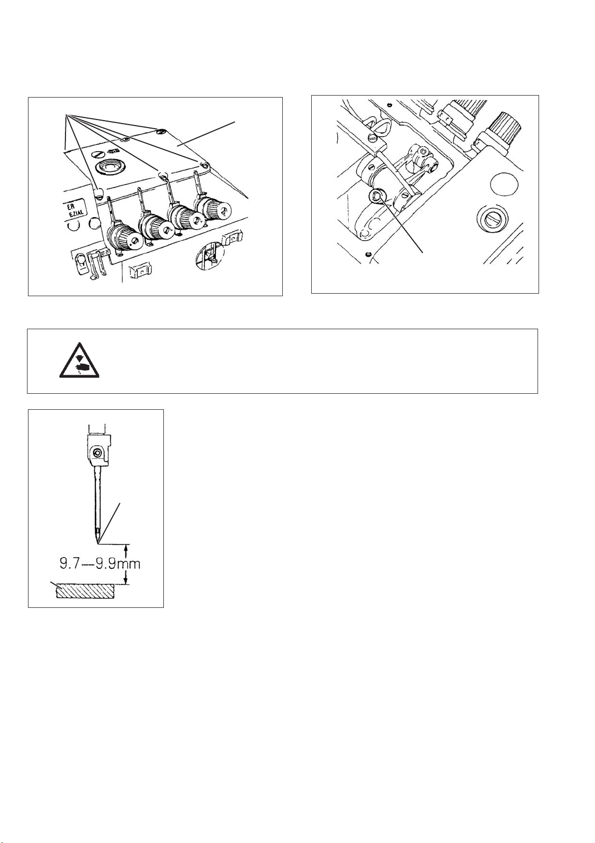
2.1 Adjusting the needle bar height
1
2
3
Caution: Risk of Injury !
Switch off the main switch.
Check and adjust the needle bar height only when the sewing unit is
switched off.
Regulation and Control
At the upper dead center of the needle bar, the distance between
needle point 4 and throat plate must be 9.7 - 9.9 mm.
–
Turn the needle bar in its upper dead center.
–
Check as to whether the distance between needle point 4 and
throat plate 5 is 9.7 to 9.9 mm.
4
Correction
–
Unscrew the lid screw 1 and remove lid 2.
–
Turn the needle bar in its upper dead center.
–
Swivel out the sewing foot.
5
–
Loosen the screw 3 up to the point that the needle bar just about
allows itself to be pushed.
–
Move the needle bar up to the point that the distance between
needle point 4 and throat plate 5 is 9.7 to 9.9 mm.
–
Tighten the screw 3.
–
Screw on the lid 2 once again.
4
Page 9
2.2 Adjusting the hook
2.2.1 Distance of the left hook from the needle
5
2,3 - 2,5 mm
1
2
3
4
Caution: Risk of Injury !
Switch off the main switch.
Check and adjust the hook only when the sewing unit is switched off.
5
Adjustment crosswise from sewing direction
Regulation and Control
In the left reversal point of the hook 5, the distance between needle
center and hook point should be 2.3 to 2.5 mm.
–
With the hand wheel, tur n the left hook to its left rever sa l poin t.
–
Check as to whether the distance between needle center and hook
point is 2.3 t o 2.5 mm.
Correction
–
Unscrew throat plate, front feed dog, as well as front and rear
needle guard.
–
With the hand wheel, tur n the hook to its left reversal point.
–
Loosen screw 1 and bring the hook to bear against the limit
stop 2.
–
Retighten the screw 1.
–
Loosen the screw 4 up to the point that the hook carrier 3 just
about allows itself to be turned.
–
Turn the hook carrier up to the point that the distance between
needle center and hook point is 2.3 to 2.5 mm.
Note
Do not yet tighten the screw 4.
3
5
Page 10

2,3 - 2,5 mm
0 - 0,05 mm
3
6
7
4
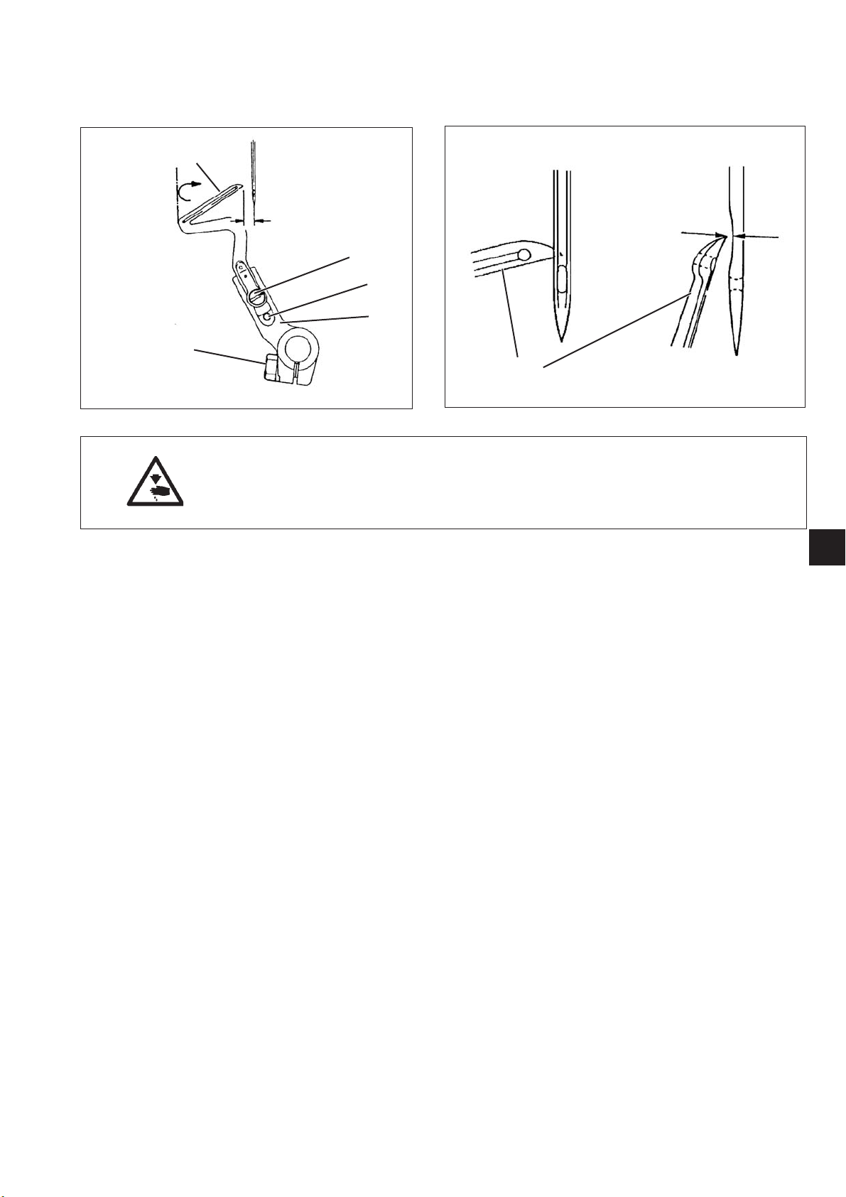
Adjustment in sewing direction
Regulation and Control
The distance between hook point 6 and needle 7 should be
0.0to0.05mm.
–
Turn the hand wheel in the direction of rotation until the hook point
is exactly at the needle center.
–
Move the hook carrier 3 up to the point that the distance between
hook carrier and needle is 0.0 to 0.05 mm.
–
Check the adjustment crosswise from sewing direction once again
and realign it, if need be.
–
Tighten the screw 4.
6
Page 11

2.2.2 Distance of the right hook from the needle
1
4
8
7
5
6
3
2
Caution: Risk of Injury !
Switch off the main switch.
Check and adjust the hook only when the sewing unit is switched off.
9
10
4,3 - 4,5 mm
Adjustment crosswise from sewing direction
Regulation and Control
When the right hook is at its upper reversal point, the distance
between hook point 9 and needle center should be 4.3 to 4.5 mm.
–
Unscrew the thread guides 1, 3 and lid 2.
–
With the hand wheel, tur n the hook to its upper dead center.
–
Loosen the screw 4 up to the point that the hook just about allows
itself to be pushed.
–
Move the hook such that the hook shaft (1) is flush with the right
side of the hook carrier.
–
Loosen the screw 6 slightly.
–
Twist the lever 5 such that a distance of 4.3 to 4.5 mm is present
between the hook point and needle center.
Take care that the bar 8 in bearing 7 does not exhibit any stiffness.
–
Tighten the screw 6.
Note
Do not yet tighten the screw 4.
3
7
Page 12

4
Adjustment in sewing direction
Regulation and Control
When the right hook crosses the left hook, the distance “A” should be
0.5 mm and the distance “B” should be 0.2 mm.
Correction
–
Turn the hand wheel in the direction of rotation until the right hook
crosses the left hook.
–
Twist and shift the right hook such that the distance “A” is 0.5 mm
and the distance “B” is 0.2 mm.
–
Tighten the screw 4 in this position.
–
Once again check all the settings and readjust, if need be.
–
Remount the thread guides 1, 2 and lid 3.
–
Adjust the thread guides according to Chapter “Thread regulation
of the serging looper”.
Note
The right serging looper is dependent on the thickness of t he needle.
For needles with Nm 60 - 80, use the hook with the characteristic
number 28, and for needles with Nm 80 - 100, use the hook with the
characteristic number 22.
8
Page 13

2.3 Adjusting the needle guard
2.3.1 Rear needle guard
1
3
2
3
4
4
Caution: Risk of Injury !
Switch off the main switch.
Check and adjust the needle guard only when the sewing unit is
switched off.
3
Regulation and Control
When the point of the left hook 3 is at needle center, the needle
guard 1 should bear against the needle and a distance of 0.0 to
0.05 mm should be present between hook point and needle.
–
Turn the hand wheel in the direction of rotation until the hook point
is positioned in the direction of the needle.
–
Check the distance between hook point and needle.
Correction of mobile version
–
Turn the hand wheel in the direction of rotation until the hook point
is positioned in the direction of the needle.
–
Loosen the screw 2.
–
Shift the needle guard 1 such that the needle guard bears against
the needle and a distance of 0.0 to 0.05 mm is present between
the hook point and the needle center.
–
Tighten the screw 2.
Correction of rigid version
–
Turn the hand wheel in the direction of rotation until the hook point
is positioned in the direction of the needle.
–
Loosen the screw 4.
–
Shift the needle guard 3 such that the needle guard bears against
3
the needle and a distance of 0.0 to 0.05 mm is present between
the hook point and the needle center.
–
Tighten the screw 4.
9
Page 14

2.3.2 Front needle guard
1
1
4
Caution: Risk of Injury !
Switch off the main switch.
Check and adjust the needle guard only when the sewing unit is
switched off.
Regulation and Control
At the bottom dead center of the needle, the distance between needle
guard 1 and needle should be 0.03 to 0.05 mm.
–
–
Correction
–
–
–
–
2
Turn the hand wheel in the direction of rotation until the needle is
exactly at its dead center.
Check the position of t he front needle guard.
Turn the hand wheel in the direction of rotation until the needle is
exactly at its dead center.
Loosen the screw 2.
Move the needle guard 1 such that the distance between needle
guard and needle is 0.03 to 0.05 mm.
Tighten the screw 2.
10
Page 15

2.4 Adjusting the feed dog
2.4.1 Feed dog position
21
1
2
Caution: Risk of Injury !
Switch off the main switch.
Check and adjust the feed dog position only when the sewing unit is
switched off.
Regulation and Control
In their highest position, the feed dogs should be horizontal.
–
Turn the hand wheel in the direction of rotation until the feed dogs
are in their highest position.
–
Check the position of the feed dogs.
Correction
–
Turn the hand wheel in the direction of rotation until the feed dogs
are in their highest position.
–
Loosen the screw 1.
–
Twi st t he s cre w 2.
Feed dogs are in horizontal position
Feed dogs are inclined backwards
3
Feed dogs are inclined forwards
–
Tighten the screw 1.
11
Page 16

2.4.2 Feed dog height
6
3
323
4
5
1
Caution: Risk of Injury !
Switch off the main switch.
Check and adjust the feed dog height only when the sewing unit is
switched off.
Regulation and Control
When the feed dogs are in their highest position, the teeth of the main
feed dog 4 should be 0.8 mm, the teeth of the differential feed dog 5
should be 0.9 to 1.0 mm and the teeth of the auxiliary feed dog 6
should be 0.6 to 0.7 mm above the upper edge of the throat plate.
–
Turn the hand wheel in the direction of rotation until the feed dogs
are in their highest position.
–
Check the position of the feed dogs with respect to the throat
plate.
Correction
–
Unscrew the throat plate.
–
Loosen the screws 1, 2 and 3 slightly.
–
Attach the throat plate once again.
–
Adjusting the height of the feed dogs.
–
Remove the throat plate.
–
Tighten the screws 1, 2 and 3.
–
Attach the throat plate and tighten the screws.
12
Page 17

2.5 Presser foot
2.5.2 Presser foot upper part EXT 3216
765 4 321
Caution: Risk of Injury !
Switch off the main switch.
Check and adjust the presser foot only when the sewing unit is
switched off.
3
Control
When the piston rod 7 is extended, the lever 6 should bear against the
screw 5 and the clearance under the sewing foot should be 4 mm.
8
Correction
–
Loosen counter nut 4 and turn screw 5 all the way down.
–
Swivel in the sewing foot.
–
Turn the hand wheel in the direction of rotation until the teeth of
the feed dog are below the throat plate upper edge.
–
7
Loosen screw 2 and press ring 1 all the way back up to limit stop.
–
Tighten screw 2 in this position.
Take care that ring 1 and lever 3 do not have any axial play.
–
Press lever 6 down until there is a distance of approx. 4 mm
between sewing foot and t hroat plate.
–
In this position, bring s crew 5 to bear against lever 6 and secure
with counter nut.
Note
In case lever 6 does not bear against screw 5 when the piston rod 7 of
the cylinder is extended, proceed as follows:
–
Loosen the nut 8.
–
Shift the cylinder 1 accordingly.
–
Tighten the nut 8.
13
Page 18

2.5.2 Presser foot
4321
Caution: Risk of Injury !
Switch off the main switch.
Check and adjust the presser foot only when the sewing unit is
switched off.
Control
The articulated sewing foot must be free of play and free-moving in its
joints.
The front sewing foot sole 1 and rear sewing foot sole 4 must parallel
to each other.
Correction of sideways inclination
–
Remove front sewing foot sole 1.
–
Turn upper part to position “Needle low”.
–
Place two approx. 5 mm wide paper strips 5 side by side under the
rear sewing foot sole 4.
–
Adjust the sideways inclination such that inner paper strip is
clamped somewhat lesser and can be more easily pulled out from
the clamp of the sewing foot than the outer paper strip.
54
14
Balancing of front and rear sewing foot sole
–
Remount the front sewing foot sole 1.
–
Turn upper part to position “Needle low”.
–
Twist adjusting screw 3 such that the front sewing foot sole just
about bears against it.
Inclination of the front sewing foot sole
The front sewing foot sole should now bear with its entire length
against the throat plate in position “Needle low”.
–
Adjust sewing foot sole with screw 2.
Page 19

2.6 Upper and lower knife
2.6.1 Changing and adjusting the upper knife
Upper part EXT 3216-03/233K
321
Caution: Risk of Injury !
Switch off the main switch.
Check and adjust the upper knife only when the sewing unit is
switched off.
Control
When the upper knife is in its lowest position, the front edge of the
blade should be 0.5 to 1.0 mm below the throat plate upper edge.
Correction
–
Turn the hand wheel until the needles are at their upper reversal
point and swivel out the sewing foot.
–
Unscrew the screw 1.
–
Remove the knife holder 2 with the knife.
–
Loosen the screw 3 and remove the knife.
–
Insert a new, sharp knife and fasten with screw 3.
–
Insert knife holder 2 and screw on lightly with screw 1.
–
Turn the hand wheel until the knife is in its lowest position.
–
Shift the knife such that it lightly bears against the lower knife and
the front edge of the blade is approx. 0.5 to 1.0 mm below the
throat plate upper edge.
3
15
Page 20

2.6.2 Changing and adjusting the lower knife
Upper part EXT 3216-03/233K
43 21
Caution: Risk of Injury !
Switch off the main switch.
Check and adjust the upper knife only when the sewing unit is
switched off.
Control
The blade of the lower knife should be flush against the upper edge of
the throat plate.
Correction
–
Remove the fabric sliding plate.
–
Swivel out the sewing foot.
–
Loosen the screw 4.
–
Pull the lower knife holder 3 to the left up to limit stop and
retighten screw 4 lightly.
–
Loosen the screw 2 and remove the old knife.
–
Insert a new, sharp knife in the guide 1 such that the blade is flush
against the upper edge of the throat plate.
–
Tighten the screw 2.
–
Turn the hand wheel until the upper knife is in its highest position.
–
Loosen screw 4 and allow the lower knife holder t o spring against
the upper knife.
–
Tighten the screw 4.
16
Page 21

2.7 Thread regulation of serging looper
10
2
1
3
4
5
9
Caution: Risk of Injury !
Switch off the main switch.
Check and adjust the thread regulation only when the sewing unit is
switched off.
8
6
7
Control
The positions of the individual thread guides and/or thread pullers is
dependent upon the material used, the sewing yarn and the stitch
type.
The following adjustment values may therefore be regarded merely as
referen c e valu es .
Correction
–
Turn the hand wheel until the right hook is at its upper reversal
point.
–
Loosen screw 10 and shift the thread puller 9 such that there is a
distance of approx. 32 mm between screw center and loop center.
–
Tighten screw 10.
Make sure that the thread puller 9 is in vertical position.
–
Loosen the screws 6 and 8 slightly.
–
Bring the thread pullers 3 and 7 to the position shown in the figure.
–
Tighten the screws 6 and 8.
–
Loosen the screw 4 slightly.
–
Bring the thread guide 5 to the position shown in the figure.
–
Tighten the screw 4.
–
Loosen the screw 2 slightly.
–
Shift the thread guide 1 such that the screw 2 is at the center of
the elongated hole.
–
Tighten the screw 2.
Note
If more or less thread is required in the seam, shift thread pullers 3
and 7 in the direction “+” or “-” respectively.
3
17
Page 22

3. Adjusting the sewing unit
3.1 Adjusting the light barrier
21
Caution: Risk of Injury !
The light barrier is adjusted when the sewing unit is switched on.
Perform the adjustment and functional test only with the greatest
care.
Align the light barrier
The light barrier 2 should be leveled at the area 1 on the upper part.
–
Loosen the screws 4 and 5.
–
Align the light barrier 3 accordingly.
–
Tighten the screws 4 and 5.
Adjusting the light barrier intensity
–
Adjust the sensitivity potentiometer 5 on the front face above the
light emitting diode 6 up to its left limit stop (least sensitivity).
–
Turn the potentiometer in clockwise direction until the light
emitting diode 6 switches on.
–
65
For safe light barrier operation, turn the potentiometer further by
another revolution in clockwise direction.
543
18
If the light emitting diode does not light up, then the light barrier
should be cleaned, readjusted or exchanged.
Page 23

3.2 Adjusting the workpiece limit stop
321
Caution: Risk of Injury !
Switch off the main switch.
Adjust the workpiece limit stop only when the sewing unit is
switched off.
Control
The workpiece limit stop 2 must bear against the sewing foot 3
completely, in order that the fabric is not pulled up between the
sewing foot 3 and the limit stop 2 while sewing.
Correction
–
Loosen the screw 1.
–
Push the workpiece limit stop 2 all the way against the sewing
foot 3.
–
Tighten the screw 1.
3
19
Page 24

3.3 Adjusting the contour guide
21
Caution: Risk of Injury !
Switch off the main switch.
Adjust the contour guide only when the sewing unit is switched off.
Control
The contour guide 1 should advance until both the lays 2 are always
guided securely while stitching down the contours.
Correction of swivel-out width
–
Loosen the clamping lever 4.
–
Shift the contour guide 1 accordingly.
–
Tighten the clamping lever 4.
Correction of punching position
–
Loosen the nut 6.
–
Twist the punch 1 accordingly.
–
Tighten the nut 6.
13
20
Page 25

3.4 Direct Drive Sewing Mode
2.4.2 Adjusting the reference
1
Caution: Risk of Injury !
Switch off the main switch.
Check and adjust the hook setting only when the sewing unit is
switched off.
3
Control
If the needle is in the position “7 mm after the bottom dead center”,
the drive belt should be applied such that the feather key 2 in the
motor shaft points to the marking 1 in the motor housing.
Correction
–
Remove the toothed belt.
–
With the hand wheel, t urn the needle bar to the position “7mm
after the bottom dead center”.
–
Twist the motor shaft such that the feather key 2 in the motor shaft
points to the marking 1 in the motor housing.
–
Apply the toothed belt once again.
7mm
bottom dead center
21
Page 26

4 Lubrication
Caution: Risk of Injury !
Oil can induce skin rashes.
Avoid long-term skin contact.
Wash yourself thoroughly after contact.
ATTENTION!
The handling and disposal of mineral oils is subject to legal regulation.
Deliver used oil to an authorised collection point.
Protect your environment.
Take care not to spill oil.
4.1 Oil change and oil filter change
2
5
1
3
4
An oil exchange with dismantled machine head must be performed 4
weeks from the initial start-up, and subsequently every 2 years.
The oil filter should be cleaned or exchanged every 2 years.
6
7
Note
If the oil pressure indicator 5 does not move downwards when the
machine head is operational, or if the oil is dirty, then the oil filter must
be cleaned or exchanged.
8
–
Unscrew the drain screw 1 and intercept the used oil in a vessel.
–
Retighten the drain screw 1.
–
Unscrew the screw 6 of the lid.
–
Screw in one of the s crews 6 into filter 8 and therewith unscrew
and remove the filter.
–
Clean or exchange the filter 8.
–
Insert new seal 7, place back the lid and tighten the screws.
–
Loosen screw 2 and fill oil until the top of the oil level indicator 3
has reached the upper marking in the oil inspection glass 4.
We recommend oil with a density of 0.865 g/cm³ at 15 ° C.
–
Reinsert the screw 2.
3
22
Page 27

5 Maintenance
Caution: Risk of Injury !
Switch off the main switch.
The sewing unit may be serviced only when it is switched off.
The maintenance jobs to be performed on a daily or weekly basis by
the operating personnel at the workplace (cleaning and lubrication)
are described in the operating instructions (Chapter 8). They are given
in the following table only for the purpose of completeness.
Jobs to be performed Operating hours
8 40 160 500
Machine head
- Remove lint and thread waste X
- Monitor oil level X
- First oil exchange X
- Subsequent oil exchange every 2 years
Control Box
- Remove lint and thread waste X
- Keep filter free X
-
Suctioning device
- Empty the container X
- Rid the s pace under the fabric sliding plate of lint and
thread waste X
Pneumatic system
- Check the water level in the pressure regulator. X
- Clean the filter insert in the maintenance unit X
- Check the leak tightness of the system X
3
23
 Loading...