


Duerkopp Adler 506-3 Operating Instruction
506-3
Instructions, complete
Operating Instructions
Installation Instructions
Service Instructions
1
2
3
Postfach 17 03 51, D-33703 Bielefeld • Potsdamer Straße 190, D-33719 Bielefeld
Telefon +49 (0) 521 / 9 25-00 • Telefax +49 (0) 521 / 9 25 24 35 • www.duerkopp-adler.com
Ausgabe / Edition: Änderungsindex Teile-Nr./Part.-No.:
10/2008 Rev. index: 01.0 Printed in Federal Republic of Germany 0791 506011

Instructions, complete
506-3
Overview
Operating table
Operating Instructions
Installation Instructions
Service Instructions
Pneumatic circuit plan
9770 506002
Interconnection-diagram
9890 506003 B
All rights reserved.
Property of Dürkopp Adler AG and copyrighted. Reproduction or publication of the content in any manner,
even in extracts, without prior written permission of Dürkopp Adler AG, is prohibited.
Copyright ©
Dürkopp Adler AG - 2008

Foreword
This instruction manual is intended to help the user to become familiar
with the machine and take advantage of its application possibilities in
accordance with the recommendations.
The instruction manual contains important information on how to
operate the machine securely, properly and economically. Observation
of the instructions eliminates danger, reduces costs for repair and
down-times, and increases the reliability and life of the machine.
The instruction manual is intended to complement existing national
accident prevention and environment protection regulations.
The instruction manual must always be available at the machine/sewing
unit.
The instruction manual must be read and applied by any person that is
authorized to work on the machine/sewing unit. This means:
– Operation, including equipping, troubleshooting during the work
cycle, removing of fabric waste,
– Service (maintenance, inspection, repair) and/or
– Transport.
The user also has to assure that only authorized personnel work on the
machine.
The user is obliged to check the machine at least once per shift for
apparent damages and to immediatly report any changes (including the
performance in service), which impair the safety.
The user company must ensure that the machine is only operated in
perfect working order.
Never remove or disable any safety devices.
If safety devices need to be removed for equipping, repairing or
maintaining, the safety devices must be remounted directly after
completion of the maintenance and repair work.
Unauthorized modification of the machine rules out liability of the
manufacturer for damage resulting from this.
Observe all safety and danger recommendations on the machine/unit!
The yellow-and-black striped surfaces designate permanend danger
areas, eg danger of squashing, cutting, shearing or collision.
Besides the recommendations in this instruction manual also observe
the general safety and accident prevention regulations!

General safety instructions
The non-observance of the following safety instructions can cause
bodily injuries or damages to the machine.
1. The machine must only be commissioned in full knowledge of the
2. Before putting into service also read the safety rules and
3. The machine must be used only for the purpose intended. Use of
4. When gauge parts are exchanged (e.g. needle, presser foot, needle
5. Daily servicing work must be carried out only by appropriately
instruction book and operated by persons with appropriate training.
instructions of the motor supplier.
the machine without the safety devices is not permitted. Observe all
the relevant safety regulations.
plate, feed dog and bobbin) when threading, when the workplace is
left, and during service work, the machine must be disconnected
from the mains by switching off the master switch or disconnecting
the mains plug.
trained persons.
6. Repairs, conversion and special maintenance work must only be
carried out by technicians or persons with appropriate training.
7. For service or repair work on pneumatic systems, disconnect the
machine from the compressed air supply system (max. 7-10 bar).
Before disconnecting, reduce the pressure of the maintenance unit.
Exceptions to this are only adjustments and functions checks made
by appropriately trained technicians.
8. Work on the electrical equipment must be carried out only by
electricians or appropriately trained persons.
9. Work on parts and systems under electric current is not permitted,
except as specified in regulations DIN VDE 0105.
10. Conversion or changes to the machine must be authorized by us
and made only in adherence to all safety regulations.
11. For repairs, only replacement parts approved by us must be used.
12. Commissioning of the sewing head is prohibited until such time as
the entire sewing unit is found to comply with EC directives.
13. The line cord should be equipped with a country-specific mains
plug. This work must be carried out by appropriately trained
technicians (see paragraph 8).
It is absolutely necessary to respect the safety
instructions marked by these signs.
Danger of bodily injuries !
Please note also the general safety instructions.

Contents Page:
Preface and General Safety Information
Part 1: Operating Instructions Cl. 506-3
(Edition 10/2008)
1. Product Description
1.1 Description of the Proper Use and Proper Application ......................... 5
1.2 ShortDescription............................................... 6
1.3 TechnicalData ................................................ 7
2. Operation
2.1 Automatic Sewing Sequence ........................................ 9
2.2 Needles and Yarns .............................................. 11
2.3 Threading the Needle Thread ....................................... 12
2.4 Changing the Bobbin ............................................. 14
2.5 ThreadTension................................................ 16
1
3. Bobbin winder ................................................ 17
4. Maintenance
4.1 Cleaning .................................................... 18
4.2 Lubrication ................................................... 20

Noise level Lc
Workstation related emission according to DIN 45635-48-B-1
Number of stitches: 1.000 min
-1
Commanding cam: (Stitches) 116
Sewing cycles: 9,7 s o n / 2,0 s off
Sewing material: 2x girdle tape 1,5 mm 1.260 g/m
Measuring point to DIN 4895 Part 1
X = 0 mm Y = -400 m Z = 300 mm
Lc: 78 dB (A)
2
4

1. Product Description
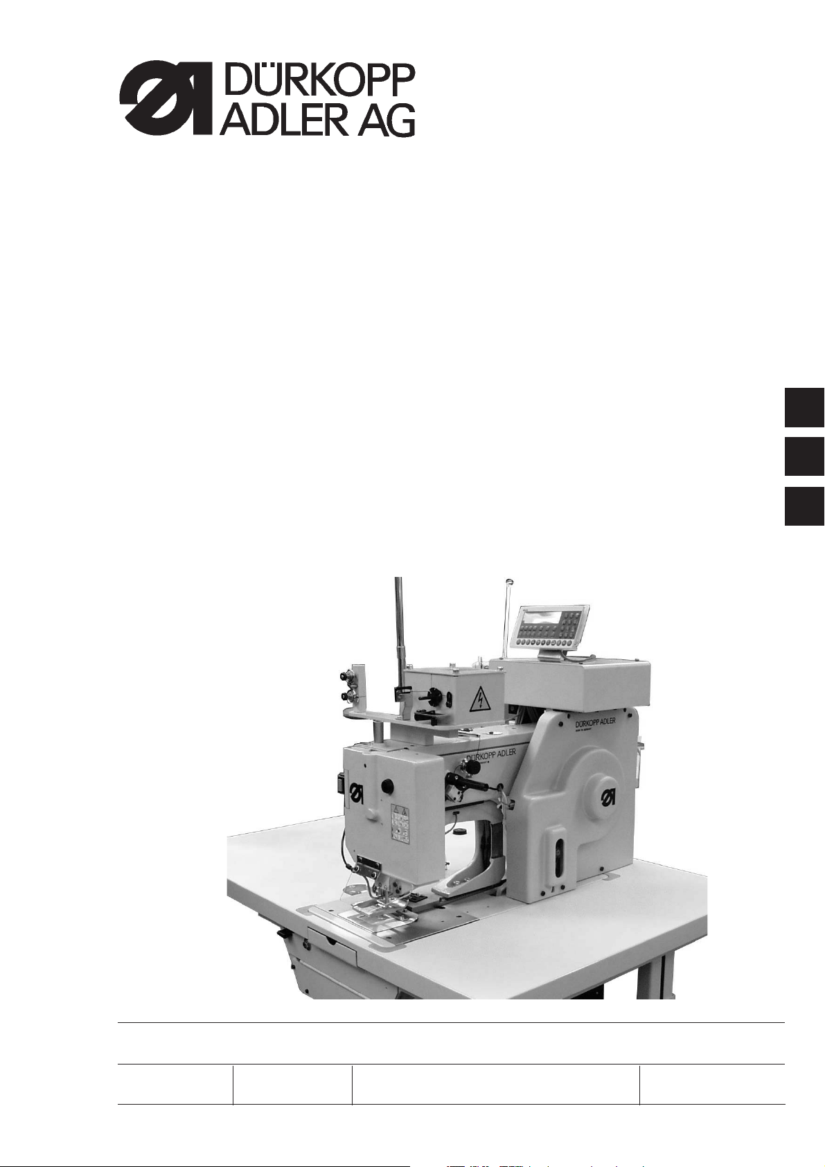
1.1 Description of the Proper Use and Proper Application
The 506-3 is a robust, heavy-duty, curve-guided single needle
lockstitch short seam unit for seams of stitch type 301.
This short seam unit is designed for use in sewing heavy-weight fabric,
as well as thick and hard leather.
Thick and hard leathers find use in the sewing on of trim pieces, in the
sewing of buckle caps, tabs, suitcases, tarpaulins, knapsacks and
backpacks.
Heavy-weight fabrics are used in the sewing of heavy-duty carrying
belts, car belts, as well as belts for aviation.
Generally only dry sewing material may be worked with this machine.
The material may be no thicker than 16 mm when pressed together by
the lowered clamping feet.
The machine must be operated with eye protection. The information to
be found printed on the yellow sign on the head cover is to be strictly
adhered to.
The seam is generally made with synthetic sewing yarns with a
dimension of 30/3 to 8/3. Those wishing to use other threads must first
evaluate the dangers arising therefrom and, if necessary, take safety
measures.
This heavy short seam unit may only be installed and operated in dry
and clean areas. If the unit is used in other areas, which are not dry and
clean, further, to be agreed upon, measures may become necessary
(see EN 60204-31: 1999).
We, as manufacturer of industrial sewing machines, presume that the
operating personnel working on our products have been given
instruction so that all normal operations and the dangers possibly
arising therefrom can be assumed to be known.
1
5

1.2 Short Description
Uniform Quality
The unit always produces a uniform seam formation.
The high thread tension necessary for the working of heavy materials is
achieved through a hinged thread lever.
Direct Power Transmission
The power transmission from the motor to the arm shaft occurs via a
special V-belt. This results in a particularly strong perforating power for
the sewing of thick materials or multiple layers.
Interchangeable Curve Disks and Material Clamps
The different seam formations are determined by easily
interchangeable curve disks.
The material guidance occurs via a pattern curve with two guide curves.
The difficult and time-consuming turning of heavy pieces of material by
the seamstress is thus unnecessary.
The transmission of the movement to the material clamps occurs via
lever systems.
By changing the lever multiplication the seam formation s izes can be
varied within certain limits.
All curve disks belonging to a stitch number range are interchangeable
among each other.
Large Put-through Area and Large Placement Surface
The large put-through area allows the making of s hort seams far from
the edge of the material. A rolling-in of flexible sewing material is
possible. The closed width base plate offers a large placement surface
and simplifies the feed.
Pneumatic Clamp Opening
The stroke of the holder clamp is a maximum 20 mm. This stroke allows
the working of almost all sewable materials and leather thicknesses.
Electric Thread Burning Device
The thread separator device separates the needle and underthread by
burning immediately at the top edge of the material. The synthetic
threads are melted together at the ends. The thus created hardening
hinders a loosening of the seam and a unthreading of the needle thread.
Control Unit Quick DA104ED
The complete c ontrol of the sewing unit occurs via a Quick control unit.
It assumes the control tasks, monitors the sewing process and
indicates operator errors and malfunctions.
ATTENTION!
These operating instructions give the key functions and describe how
operator-level parameter values are changed by the operator.
For a detailed description of the control unit, please consult the enclosed
current issue of the operating manual of the motor manufacturer.
6