


Duerkopp Adler 4220i-6 Service Manual

Instructions for service
4220i - 6
Minerva Boskovice, a.s., Sokolská 60, CZ - 680 17 Boskovice
Tel.: +420-516-453434, 453433, 494111 Fax: +420-516-452165 http://www.minerva-boskovice.com
Edition: 09/2006 Printed in Czech Republic S735 000736

CONTENTS:
1. General safety instructions ............................................................................................................................................... 1
Introduction .......................................................................................................................................................................... 1
2.
3. Head of the sewing machine .............................................................................................................................................. 2
3. 1 Hook and hook post ................................................................................................................................................................ 2
.. 3.1.1
3.1.2 Height setting of the hook
3.1.3 Setting the distance of the hook from the needle
3.1.4 Angular setting of the hook (timing)
3.1.5 Protection of the needle and of the hook point
3.1.6 Setting of the bobbin case opener
3.1.7 Setting the regulation of the hook lubrication
3.1.8 Replacement of the hook
3.1.9 Setting the gear
3.1.10 Dismantling of the hook post
3.2 Needle and thread mechanism ................................................................................................................................. 5
3.2.1 Description
3.2.2 To check the handwheel angular adjustment
3.2.3 Height setting of the needle bar
3.2.4 Angular setting of the pin of the thread mechanism
3.2.5 Side setting of the needle bar holder
3.2.6
3.3 Throat plate and its post ........................................................................................................................................................ 7
3.3.1 Description
3.3.2 Mounting and removing the throat plate and its insert
3.3.3 Side setting of the throat plate post
3.4 Thread tensioners and limiter ................................................................................................................................. 8
3.4.1 Description
3.4.2 Setting the tension of main and auxiliary tensioners
3.4.3 Setting the tensioning mechanisms of the main tensioners
3.4.4 Setting the adapting spring
3.4.5 Setting the thread limiter
3.5 Feeding mechanism of the bootom feed ...........................................................................................................................10
3.5.1 Description
3.5.2
3.6 Feeding mechanism of the top roller ................................................................................................................................14
3.6.1 Description
3.6.2 Feeding clutch
3.6.3 Side setting of the indented lower pulley
3.6.4 Side setting of the indented upper pulley
3.6.5 Setting the tensioning roller
3.6.6 Replacement of the indented belt
Description
Setting the needle (the needle bar holder)
Stitch length mechanism
3.5.2.1 Setting of the horizontal component of the feeder movement
(setting of the upper feeding eccentric)
3.5.2.2 Setting of the vertical component of the feeder movement
3.5.2.3 Setting of the feeder position against the throat plate
3.5.2.4 Setting of the height of the feeder teeth, setting of the feeding balance beam
3.5.2.5 Forward and rearward stitch length distribution (rough)
3.5.2.6 Forward and rearward stitch length distribution (fine)
3.5.2.7 Setting of the control knob (including the stitch length limitation)
3.5.2.8 Feeder replacement
3.6.2.1 Description
3.6.2.2 Setting of the feeding pitch
3.6.2.3 Setting of the lower eccentric
3.6.2.4 Setting the engagement and disengagement of the clutch

3.6.7 Top roller
3.6.7.1 Selection of the top roller diameter
3.6.7.2 Forward, rearward and side setting
3.6.7.3 Setting the gear clearance and in the mounting of the top roller
3.6.7.4 Setting of the height and of the pressing force of the top roller
3.6.7.5 Replacement of the top roller
3.7 Setting the presser foot lift .................................................................................................................................................. 19
Bobbin winder ...................................................................................................................................................................... 20
3.8
3.8.1
Description
3.8.2 Setting the bobbin winder stop
3.8.3 Setting the friction gear
3.9 Safety clutch .......................................................................................................................................................... 21
3.9.1
Description
3.9.2 Setting the disengaging moment
3.10 Indented belt transmission ................................................................................................................................... 21
3.10.1
Setting the tensioning roller of the indented belt
3.10.2 Replacing the indented belt
3.11 V-belt, motor - head .............................................................................................................................................. 22
3.11.1
Tensioning
3.11.2 Replacing the V-Belt
3.12 Driving toothed belt ............................................................................................................................................................... 22
3.12.1
To exchange the driving toothed belt
3.13 Lubrication .............................................................................................................................................................................. 23
Description
3.13.1
3.13.2 Refilling oil
3.13.3 Multiple oil use
4. Thread trimming .................................................................................................................................................................................24
4.1
Description of the trimming mechanism
4.2 Setting the pickup roller
4.3 Setting the cam
4.4 Setting the fork
4.5 Setting the moving knife
4.6 Setting the fixed knife
4.7 Setting the retaining spring of the hook thread
4.8 Setting switching of the electromagnets
5. Lifting the top roller by electromagnet ........................................................................................................................... 26
Description
5.1
5.2 Setting the electromagnet pin
5.3 Setting the electromagnet current
5.4 Assembly of the top roller lifting electromagnet
6. Backtacking using electromagnet .................................................................................................................................... 27
Description
6.1
6.2 Electromagnet height setting
6.3 Setting the position of push-buttons
6.4 Change of the function of push-buttons
7. Connecting the electric elements on the machine head ................................................................................................ 28
Drive, control panel, position sensor ......................................................................................................................................... 28
8.
Maintenance (table of operations) ............................................................................................................................................... 29
9.
Setting the machine according to the sewing category ............................................................................................................ 29
10.
Introduction
10.1
10.2 Table of setting the machine according to the sewing category

1. General safety instructions
The non-observance of the following safety instructions can cause bodily injuries or damages to the machine.
1. The machine must only be commissioned in full knowledge of the instruction book and operated by persons with appropriate
training.
2. Before putting into service also read the safety rules and instructions of the motor supplier.
3. The machine must be used only for the purpose intended. Use of the machine without the safety devices is not permitted.
Observe all the relevant safety regulations.
4. When gauge parts are exchanged (e.g. needle, top roller, needle plate, feed dog and bobbin) when treading, when the
workplace is left, and during service work, the machine must be disconnected from the mains by switching off the master
switch or disconnecting the mains plug.
5. Daily servicing work must be carried out only by appropriately trained persons.
6. Repairs, conversion and special maintenance work must only be carried out by technicians or persons with appropriate
training.
7. For service or repair work on pneumatic systems the machine must be disconnected from the compressed air supply system.
Exceptions to this are only adjustments and function checks made by appropriately trained technicians.
8. Work on the electrical equipment must be carried out only by electricians or appropriately trained persons.
9. Work on parts and systems under electric current is not permitted, except as specified in regulations DIN VDE 0105.
10. Conversions or changes to the machine must be authorized by us and made only in adherence to all safety regulations.
11. For repairs, only replacement parts approved by us must be used.
12. Commissioning of the sewing head is prohibited until such time as the entire sewing unit is found to comply with EC
directives.
It is absolutely necessary to respect the safety instructions marked by these signs.
Danger of bodily injuries !
Please note also the general safety instructions.
IMPORTANT WARNING
In spite of all safety measures made on the machines, inappropriate actions of the operator may lead to dangerous situations. In
industrial sewing machines, attention should be paid to the following still remaining possible sources of injury:
1. Moving sewing needle
- risk of injury when sewing with raised pressure foot or top roller, because the finger guard is then positioned too high,
- risk of injury when inadvertently threading down of the motor threadle.
2. Moving thread take-up lever
- risk of injury when inadvertently or intentionally inserting the finger(s) between the thread take-up lever and its guard.
3. Moving pressure member
- risk of injury when holding sewn work in immediate vicinity of the pressure member and beginning to insert under the
pressure member a considerably thicker sewn work portion,
- risk of injury when sinking the pressure member.
4. When switched off, the clutch motor slows down by inertia but would be reactivated by an accidental treading down of the
motor treadle. To avoid such risk, it is advised to hold the handwheel by hand and slightly to depress the motor treadle.
2. Introduction
This service book contains instruction for regulating the mechanisms of the sewing machine head.
The instructions for use and for putting the machine into operation and for the control of the stopmotor are not included in this
service book, but they are supplied as separate publications.
This service book is universal for all subclasses of the machine - it contains setting procedures for all elements which may be
placed on the machine of the given class. When the supplied subclass of this machine does not include some element, then it is
possible to leave out the respective parts of the instructions. The optional equipments of the machine and the respective
configurations of the subclasses of the machine are given in the operating instructions.
This sewing machine disposes of a large extent of its use. The machine should be set with respect to the parameters of the sewn
material, the sewing thread etc. The setting for the individual categories is given in the chapter 11.2.
For setting the machine, simple setting aids are used which are included in the accessory of the machine. Besides these aids,
universal measuring devices are used, such as slide calliper, feeler gauges and dynamometer for measuring the thread tension.
1
11
12
10
13
3. Head of the sewing machine
2
9
5
1
6
34
8
7
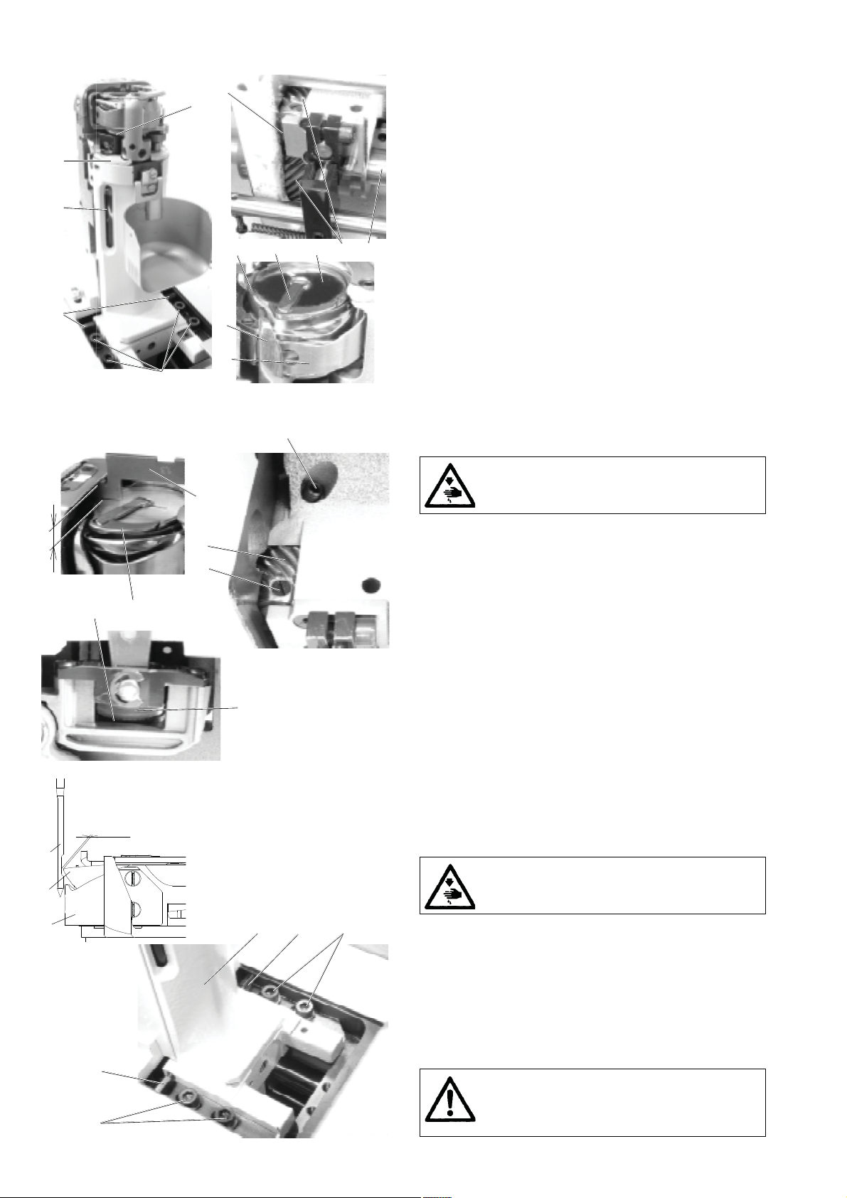
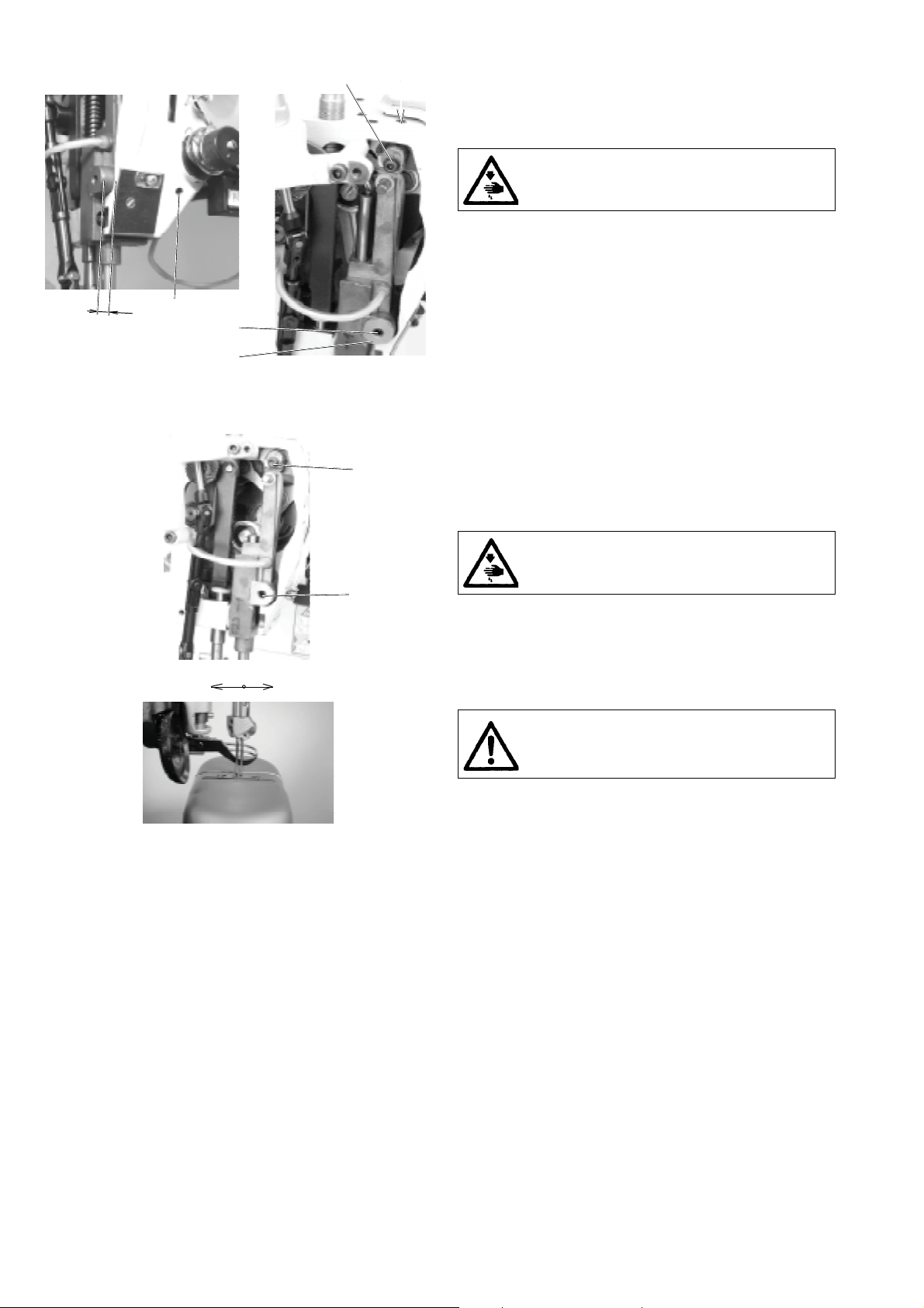
3.1 Hook and the hook post
3.1.1 Description
The hook (1) is mounted on the shaft (2) and is driven by the
gear (3) from the shaft (4).
The shaft of the hook (2) is slidably mounted on the top, in
post and, on the bottom, in a needle bearing.
The hook is provided with a lever (5) which is tilted when
removing the bobbin (6). The protecting sheet (7) protects
against the collision of the needle with the hook point. The
bobbin case opener (8) is driven by the eccentric (9) on the
shaft (2).
The oil tank (10) contains oil supply for the hook lubrication.
Superfluous oil is taken by thefelt piece (11) used to lubricate
sliding mounting hook shafts. The wick connected to the felt
piece (11) lubricates the gearing (3).
The screws (12) serve for taking up the clearance of the gear.
The screws (13) fasten the post to the bedplate.
A
2
1
7
2
max. 0,1
4
5
1
7
3
5
6
4
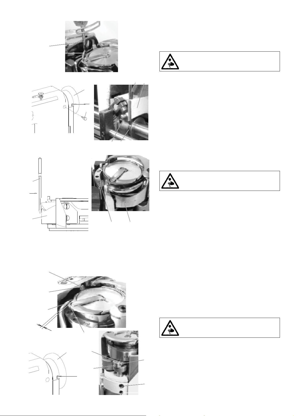
3.1.2 Height setting of the hook
The designated distance A should be 5.3 mm.
Caution! Danger of injury!
Switch off the main switch ! Before starting the
setting operation, wait until the motor stops!
- Loosen both screws (1).
By axial shifting of the bushing (2) set the axial clearance of
-
the wheel (3) to the least value still ensuring easy rotation
of the shaft (4) with the fixed wheel (3).
- Tighten both screws (1).
- Loosen both screws (5).
- Shift axially the shaft (4) with the hook (6) so as to obtain
the required distance A. For setting up use the setting
gauge (7) as per the repective figure.
- Carefully retighten the screws (5) after the adjustment.
Caution! One of these screws must bear on the flat of the
shaft (4).
3.1.3 Setting the distance of the hook from
the needle
The hook point (1) is set up to the maximum distance of
0.1 mm from the bottom of the needle recess (2). For the
sewing categories 1 and 2, the needle size 100 is set, for the
sewing categories 3 and 4, it is the needle size 160.
Caution! Danger of injury!
Switch off the main switch ! Before starting the
setting operation, wait until the motor stops!
6
54
- Loosen only one screw (4).
- Loosen the screws (5) and tighten them only slightly.
- Shift the hook post (6) at the determined distance between
the needle and the hook point.
- Tighten carefully the screw (4) (be sure not to damage the
threads!)
- Tighten duly the screws (5).
- Check up the setting using a narrow strip of thin paper and
proceed to the eventual correction of setting.
Caution!
When changing substantially the sewing category, the protecting sheet of the hook (7) should
be set up.
2
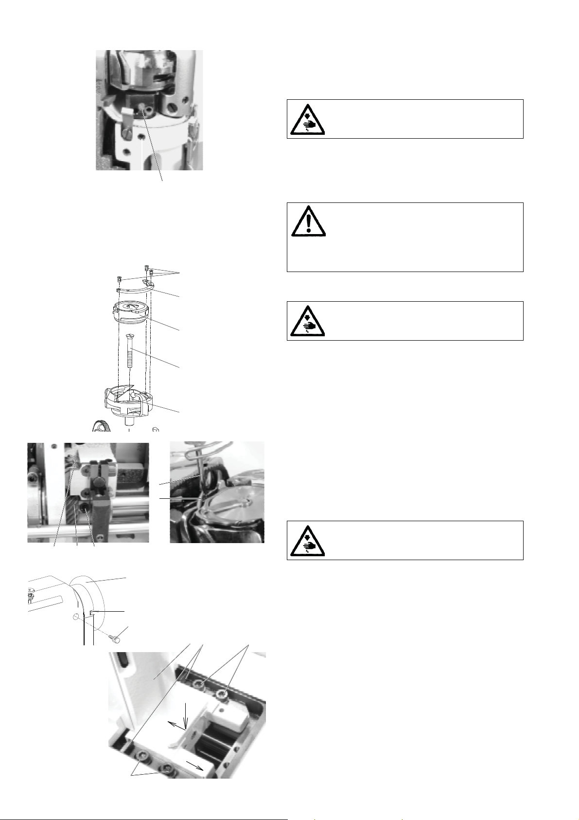
3.1.4 Angular setting of the hook (timing)
The hook is to be angularly set in such a way that the hook
point (1) is opposite the needle at the moment, when the
2
1
needle shifts by 2.5 mm from its bottom dead center. This
corresponds to the 2O5° on the scale of the handwheel (3).
Caution! Danger of injury!
Switch off the main switch! Before starting the
setting operation, wait until the motor stops!
- Remove the throat plate.
- Turn the handwheel (3) to the 2O5° and fix it with the screw
(4) which is component part ot the accessory of the machine
(tighten it carefully).
- Loosen the screws (5).
- Turn the hook into the required position.
-
Pass the locating pin (7) contained in the machine accessories through the hole in thehook post bed (8) and insert
it into the groove of the gear wheel (6). In this way, thewheel
is axially set.
- Tighten to the maximum the screws (5) and take the locating
pin (7) out.
205
8
7
3
o
4
6
5
3.1.5 Protection of the needle and of the hook point
The protecting sheet (1) is to be set up in such a way that the
clearance between the protecting sheet and the needle (2) is
the least possible.
Caution ! Danger of injury!
2
5
- Remove the throat plate and the movable trimming knife.
- Unscrew the screw (3).
- Put the screwdriver into the hole of the screw (3) and, using
the regulating screw, set up the required clearance between
1
3
1
the needle (2) and the protecting sheet (1). When turning to
the right, the protecting sheet shifts out from the groowe
and inversely.
- Check up the protecting effect in pushing against the needle
in the sense of the arrow (5). The hook point must not catch
the needle. If so, set up the protecting effect, correct eventually the setting of the distance of the hook point from the
needle according to the paragraph 3.1.3.
- Screw in the screw (3).
Switch off the main switch! Before starting the
setting operation, wait until the motor stops!
3
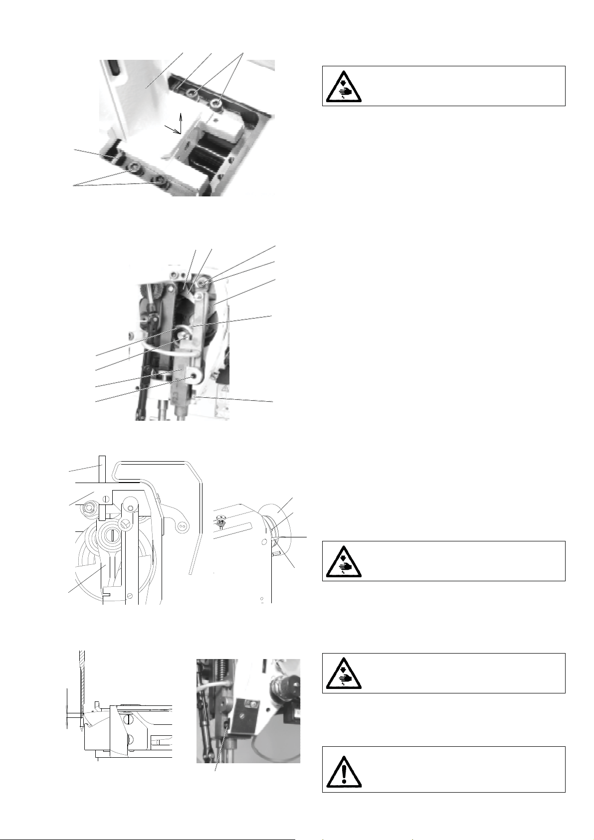
3.1.6 Setting of the bobbin case opener
The bobbin case opener (1) is to be set in such a way that, at
4
1
A
2
5
7
9
8
o
308
6
10
3
the moment when the opener is in its dead centre, there would
be a clearance A between the opener (1) and the projection
(2), whereas the finger (3) bears on the projection (4), A =
0.7 mm for the sewing category 1 and 2, A = 0.3 mm for the
sewing category 3 and 4.
Caution ! Danger of injury!
Switch off the main switch! Before starting the
setting operation, wait until the motor stops!
- On the handwheel (5), set the angle of 308° (the hook is in
its dead centre).
- Loosen the screw (6).
- Turn the eccentric (7) in such a way that the required
clearance between the elements (1) and (2) is attained.
By turning the screw (10), set the height of the eccentric (7)
in such a way that it is in its highest position in retaining
the minimum clearance between the slide (8) and the fork
(9).
- Tighten duly the screw (6).
3.1.7 Setting the regulation of the hook lubrication
Oil is wiped from the lubrication wick by the surface of the
hook eccentric and is then supplied by centrifugal force into
the hook path (7). The intensity of oil supply is regulated by
turning the screw (3).
Caution! Danger of injury!
Switch off the main switch ! Before starting the
setting operation, weit until the motor stops!
- To reduce the oil supply, turn the screw (3) to the right.
- To increase the oil supply, turn the screw (3) to the left.
- After the adjustment, loosen the screw (4) and set the height
3
4
1
of the oil tank so as toensure reliable contact between the
surface of the eccentric and the lubrication wick.
Caution!
The quantity of the fed oil has been set up in the
manufacturing factory. This setting is to be done
only in emergency events. A bad setting of the quantity of the
fed oil or of the height of the lubrifying tube may cause a
rapid wear or a seizure of the hook.
2
3
4
5
3.1.8 Replacement of the hook
Caution! Danger of injury!
Switch off the main switch ! Before starting the
setting operation, weit until the motor stops!
- Remove the throat plate and the trimming knife
with its holder.
- Unscrew the screws (1) and remove the splice (2).
- After having suitably turned a bit the hook, remove the
bobbin case (3).
- Unscrew thorougly the screw (4).
- Remove the body of the hook (5) upwards.
- When mounting, the procedure is inverse.
together
3.1.9 Setting the gear
The mutual angular orientation of the gear wheel (1) relative
to the gear wheel (2) should ensure the accessibility of the
4
3
521
6
o
205
7
9
8
10
10
screw (5) at the moment when the hook point comes to lie
opposite the needle (4). The wheel (2) is to be set with its gear
rim symmetrically to the centre of the gear wheel (1). The
clearance between the gear wheels is to be the least possible.
Caution ! Danger of injury!
Switch off the main switch! Before starting the
setting operation, wait until the motor stops!
- Set the angle of 2O5° on the handwheel (6) and lock it with
the screw (7).
- On the removed post of the hook (8), according to the paragraph 3.1.10, the hook point (3) is to be turned a bit
according to the illustration.
- Turn the gear wheel (2) into the suitable position and insert
the post of the hook into the machine according to the
respective arrows. Check up, whether the screw (5) is accessible and, if not, repeat the procedure.
- Set the the distance of the hook from the needle according
to the paragraph 3.1.3.
- Set the precise angular displacement of the hook according
to the paragraph 3.1.4.
- Loosen the screw (10) and tighten them slightly.
- Set the clearence in the gear in turning the screws (9). Check
up, whether the gear has a clearance during the whole
revolution of the hook. Turn the handwheel step by step by
15° and, with each step, grasp the hook and try, if there is an
angular dead travel. Tighten carefully the screws (9).
- Tighten duly the screws (10) and try anew the clearance of
the gear.
4
1
5
3.1.10 Dismantling of the hook post
Caution ! Danger of injury!
Switch off the main switch! Before starting the
setting operation, wait until the motor stops!
- Loosen only one screw (5).
- Unscrew the screws (6).
- Shift the post(1) in the sense of the arrows and remove it
out from the machine.
- When mounting it, proceed inversely.
6
5
6
3
2
9
10
11
4
5
12
6
7
8
1
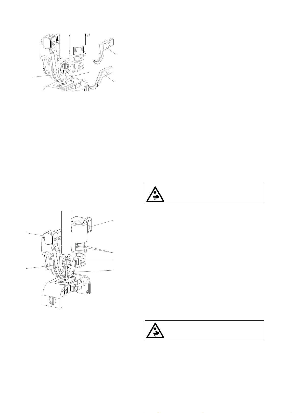
3.2 Needle and thread mechanism
3.2.1 Description
The take-up lever (1) is mounted in ball bearings, both at the
spot of its suspending on the connecting rod (2) and in the
mounting on the loop (12). The take-up lever is of aluminum
and is provided with a stuck-in eye for two threads.
The connecting rod (2) is mounted on the eccentric pin (3).
The needle rod holder (4) is mounted through the pivot (5) in
the arm (6).
in its correct position with the screw (8) in the pin (7) fastened
on the machine arm.
The connecting rod (10) of the needle bar (11) on the loop
(12) is mounted in a ball bearing and it is slidingly mounted
on the needle bar carrier. The mechanism is lubricated by means
of a central-wick lubricating system.
In the upper part, the needle bar holder (4) is fixed
3.2.2 To check the handwheel angular adjustment
The handwheel (5) must be situated in its precise position
relative to the needle and thread mechanism. This position is
2
3
1
1
given by a pin (2), which locks the connecting rod of the
needle rod (1) through a hole in the arm (3). In this position,
the indicator (6) of the handwheel must show O. The position
5
is fixed by the handwheel screw (4) contacting a small flat
4
surface provided on the upper shaft.
The correct adjustment of the angular position has been car-
o
0
ried out at the producers.
Caution ! Danger of injury!
6
Switch off the main switch! Before starting the
setting operation, wait until the motor stops!
3.2.3 Height setting of the needle bar
At the moment, when the hook point passes around the needle,
the upper edge of the needle eye must be about 1 mm below
the hook point. In an opposite case, it is necessary to set the
height of the needle bar as follows:
Caution ! Danger of injury!
Switch off the main switch! Before starting the
setting operation, wait until the motor stops!
- Remove the front guard.
- Loosen the screw (1) of the needle bar carrier
- Set the correct height of the needle bar and tighten anew
the screw (1).
Caution !
An incorrect setting of the needle bar height may
1
cause the striking of the hook point against the
needle.
5
4
A
1
2
5
3
3.2.4 Side setting of the needle bar holder
The correct position of this holder is in such case, when the
needle bar is lined up with the presser-foot bar. The needle bar
holder can be set as follows:
Caution! Danger of injury!
Switch off the main switch! Before starting the
setting operation, wait until the motor stops!
- Loosen the screw (1) of the pin (2).
- Loosen the screw (3) of the guide pin (4).
- In shifting the pin (2) set the needle bar holder on the
measure A = 8 mm
arm and the front face of the safety bolt (5) of the needle
bar holder)
- The guide pin (4) is to be set in such a way that the needle
bar holder moves easily.
- Tighten the screws (1 and 3).
/at the same time the pin (4) shifts/.
(distance between the front face of the
1
3.2.5 Setting the needle (the needle bar holder)
When moving the needles through the throat plate, the needles
must pass through the centre of the holes in the insert of the
throat plate.
Caution ! Danger of injury!
Switch off the main switch! Before starting the
setting operation, wait until the motor stops!
2
-
Using the handwheel, set the needles in the position, when
the needles starts passing into the the throat plate.
- Loosen the screw (1) fixing the needle bar holder.
- Moving the needles in the longitudinal direction around
the pin (2), set the needles into the axis of the holes.
- Tighten the screw (1) and check the given setting.
Caution!
A faulty setting may cause bending or breaking of
needles against the throat plate insert.
6

3.3 Throat plate and its post
3.3.1 Description
1
2
45
7
6
1
2
7
The throat plate (1) is always for the given stitch width of
needles and universal for all respective categories of sewing
(see Tab. sewing equipments - Spare parts list).
In the throat plate there is mounted an exchangeable throat
plate insert (2). For each stitch width of needles, it is possible
to supply several throat plate inserts differing one from
another by the width of the piercing hole.
3.3.2 Mounting and removing the throat plate and
its insert
When mounting the throat plate (1), the fingers (4) of the
bobbin case must fit into the recess (5) of the throat plate.
When dismantling the throat plate insert (2), it is necessary to
unscrew both screws (6) and to remove the throat plate insert.
Caution! Danger of injury!
Switch off the main switch! Before starting the
setting operation, wait until the motor stops!
- Turn the fingers (4) in the sense towards the throat plate
(1).
Place the throat plate (1) onto the post.
-
- Screw in the screws (7).
Mount the throat plate insert (2).
-
- Tighten the screws (6).
- When removing the insert, proceed in an inverse sequence.
3.3.3 Side setting of the throat plate post and
A
5
The throat plate post (1) and the needle holder (2) are to be
mutually positioned in such a way, so that, with the given
6
3
stitch width A, both needles pass through the centres of the
needle penetration holes.
- Loosen the screw (3) of the needle bar carrier.
- Shift the needle bed (2) in such a way, so that the required
- Tighten up the screw (3) and check up the setting.
- Loosen the screws (4) /from the rear side of the post too/.
- Shift the post (1) in the right direction in such a way, so that
2
- Tighten up the screws (4) and check up the correctness of
setting of the needle bed shifting
Caution! Danger of injury!
Switch off the main switch! Before starting the
setting operation, wait until the motor stops!
stitch width of needles A" is attained.
both needles pass through the centres of the needle penetration holes.
setting.
3.3.4 Setting the needle (the needle bar holder) in
the direction of sewing (fine setting)
Caution! Danger of injury!
Switch off the main switch! Before starting the
setting operation, wait until the motor stops!
- Loosen the screw (5).
In turning the needle bar holder (6), set the needle against
-
1
4
the centres of the needle penetration holes.
- Tighten up the screw (5) and check up the setting.
Caution!
A faulty setting may cause bending or breaking of
needles against the throat plate insert.
7
3.4 Front and rear guides of needles
3.4.1 Description
The front guide (1) and the rear guide (2) are used together
for stitch widths of a tandem arrangement. With the sewing
categories 300 and 400, it is possible to replace these guides
4
2
1
3
by one guide (4) /the rear guide and the side guide in one
guide/.
For stitch widths with needles side by side, the rear guide (3)
is used only. All guides serve for holding the sewn material
against the throat plate. In addition to this, they contribute to
a as well and protect the needles in guiding them into the
piercing holes.
3.4.2 Setting the front guide
The front guide is universal for tandem stitch widths and for
all categories of sewing. It should be set in such a way that,
from the point of view of the operator, it protects the right
needle from the left-hand side. In the that, when backward
stitching, it could not negatively influence the stitch locking.
Its correct height is set up according to the sewn material
1-2 mm above the bottom edge of the feeding wheel. For
harder materials, it is set a bit lower and inversely.
Caution! Danger of injury!
Switch off the main switch! Before starting the
setting operation, wait until the motor stops!
- Loosen the screw (4) and set the correct height of the guide
(1). Tighten then the screw.
5
4
- Loosen the screw (5) and set the guide (1) in the direction
of sewing in front of the left needle at the moment, when
the needle starts piercing the material and set, at the same
time, the side clearance between the guide and the righthand needle, tighten then the screw.
- Check up the influence of the setting on the stitch locking.
7
6
3.4.3 Setting the rear guide
1
2
For different stitch widths of needles there is always used, for
all sewing categories, the respective guide (in each sewing
set there is supplied a corresponding guide). The rear guide
protects the left needle from the right-hand side. It is to be set
in such a way in the direction of sewing that it favourably
influences the stitch locking even when sewing the radii. Its
correct height is set 1-2 mm above the bottom edge of the
feeding wheel, namely according to the hardness of the sewn
material.
Caution! Danger of injury!
Switch off the main switch! Before starting the
setting operation, wait until the motor stops!
- Loosen the screw (6) and set the guide (2) in the direction
of sewing behind the right needle at the moment when the
needle leaves the sewn material, tighten up the screw.
- Loosen the screws (7) and set the guide in its correct height
and, at the same time, set the side clearance between the
guide and the left needle, tighten up the screw.
- Check up the influence of setting on the stitch locking.
8