


Instructions for service
4181 - 1
Minerva Boskovice, a.s., Sokolská 60, CZ - 680 17 Boskovice
Tel.: +420-501-453434, 453433, 494111 Fax: +420-501-452165 http://www.minerva-boskovice.com
Edition: 04/2002 Printed in Czech Republic 735 342 000 428

CONTENTS:
1. General safety instructions .......................................................................................................................................................... 1
2. Introduction .......................................................................................................................................................................................... 1
3. Head of the sewing machine ......................................................................................................................................................... 2
3. 1 Hook and hook post ............................................................................................................................................................. 2
3.1.1 Description
3.1.2 Height setting of the hook
3.1.3 Setting the distance of the hook from the needle
3.1.4 Angular setting of the hook (timing)
3.1.5 Protection of the needle and of the hook point
3.1.6 Setting of the bobbin case opener
3.1.7 Setting the regulation of the hook lubrication
3.1.8 Replacement of the hook
3.1.9 Setting the gear
3.1.10 Dismantling of the hook post
3.2 Needle and thread mechanism ................................................................................................................................................ 5
3.2.1 Description
3.2.2 To check the handwheel angular adjustment
3.2.3 Height setting of the needle bar
3.2.4 Side setting of the needle bar holder
3.3 Throat plate and its post ................................................................................................................................................... 7
3.3.1 Description
3.3.2 Mounting and removing the throat plate and its insert
3.3.3 Setting the needle (the needle bar holder) in the direction of sewing (fine setting)
3.3.4 Side setting of the throat plate post
3.4 Thread tensioners and limiter ........................................................................................................................................... 8
3.4.1 Description
3.4.2 Setting the tension of main and auxiliary tensioners
3.4.3 Setting the tensioning mechanism of the main tensioner
3.4.4 Setting the adapting spring
3.4.5 Setting the thread limiter
3.4.6 Setting the additional thread limiter
3.5 Feeding mechanism of the needle feed and of the lower feed wheel ..................................................................... 10
3.5.1 Description
Stitch length mechanism
3.5.2
3.5.2.1 Setting the upper eccentric
3.5.2.2 Setting the prop
3.5.2.3 a Forward and rearward stitch length distribution (rough)
3.5.2.3 b Forward and rearward stitch length distribution (fine)
3.5.2.4 Setting of the control knob (including the stitch length limitation)
Setting the needle feed (rough)
3.5.3
3.5.4
Lower feed wheel
3.5.4.1 Feeding clutches
3.5.4.1.1 Description
3.5.4.1.2 Setting the lever of the second step of feeding(angle, position)
3.5.4.1.3 Setting of the lower eccentric
3.5.4.1.4 Setting the engagement and disengagement of the clutches
3.5.4.2 Wheel feeder and its post
3.5.4.2.1 Height setting of the feeder and tensioning of the chain
3.5.4.2.2 Replacement of the feeder
Setting the top roller (pressing force, height)
3.5.5
3.6 Feeding mechanism of the top roller ............................................................................................................................ 15
3.6.1 Description
3.6.2 Side setting of the indented lower pulley
3.6.3 Side setting of the indented upper pulley
3.6.4 Setting the tensioning roller
3.6.5 Replacement of the indented belt
3.6.6 Setting the feeding difference
3.6.7 Replacement of the friction wheels of the drive conversion unit
Top roller
3.6.8
3.6.8.1 Selection of the top roller diameter
3.6.8.2 Forward, rearward and side setting
3.6.8.3 Setting the gear clearance and in the mounting of the top roller
3.6.8.4 Replacement of the top roller
3.7 Setting the presser foot lift ................................................................................................................................................ 19

3.8 Bobbin winder ..................................................................................................................................................................... 2 0
3.8.1 Description
3.8.2 Setting the bobbin winder stop
3.8.3 Setting the friction gear
3.9 Safety clutch ......................................................................................................................................................................... 2 1
3.9.1 Description
3.9.2 Setting the disengaging moment
3.10 Indented belt transmission ............................................................................................................................................... 2 1
3.10.1 Setting the tensioning roller of the indented belt
3.10.2 Replacing the indented belt
3.11 V-belt, motor - head ............................................................................................................................................................ 2 2
3.11.1 Tensioning
3.11.2 Replacing the V-Belt
3.12 Driving toothed belt ............................................................................................................................................................. 22
3.12.1 To exchange the driving toothed belt
3.13 Lubrication ..............................................................................................................................................................................2 3
3.13.1 Description
3.13.2 Refilling oil
3.13.3 Multiple oil use
4. Thread trimming ............................................................................................................................................................................... 24
4.1 Description of the trimming mechanism
4.2 Setting the pickup roller
4.3 Setting the cam
4.4 Setting the fork
4.5 Setting the moving knife
4.6 Setting the height of the fixed knife and of the retaining spring of the lower thread
4.7 Setting the fixed knife
4.8 Setting the retaining spring of the hook thread
4.9 Setting switching of the electromagnets
5. Material edge trimming ................................................................................................................................................................ 27
5.1 Description of the trimming mechanism
5.2 Dismantling and assembly of the motor - trimming drive
5.3 Setting of the trimming knife lifting
5.4 Replacement and setting of the trimming knife position
5.4.1 Replacement of the knife and setting of the distance between the knife and the throat plate insert
5.4.2 Setting of the knife position (turning) in the sewing direction
5.4.3 Height setting of the knife
5.5 Setting of engaging and disengaging of the trimming mechanism, of the angaging and carried lever stop
5.5.1 Description
5.5.2 Setting of the engaging lever stop
5.5.3 Setting of the position (shifting) of the carrying lever
5.5.4 Setting of the carried lever stop
5.5.5 Setting of the trimming mechanism engagement
5.5.6 Setting of the torsional moment of the return spring
5.6 Sharpening of the knives
5.7 Sewing without trimming
6. Lifting the top roller by electromagnet ...................................................................................................................................... 3 1
6.1 Description
6.2 Setting the electromagnet pin
6.3 Setting the electromagnet current
6.4 Assembly of the top roller lifting electromagnet
7. Backtacking using electromagnet ................................................................................................................................................ 32
7.1 Description
7.2 Electromagnet height setting
7.3 Setting the position of push-buttons
7.4 Change of the function of push-buttons
8. Connecting the electric elements on the machine head ........................................................................................................ 3 3
9. Drive, control panel, position sensor ....................................................................................................................................... 33
10. Lighting ............................................................................................................................................................................................ 33
10.1 Mounting on the machine head
10.2 Lamp replacement
11. Maintenance (table of operations) ............................................................................................................................................. 3 4
12. Setting the machine according to the sewing category .......................................................................................................... 34
12.1 Introduction
12.2 Table of setting the machine according to the sewing category

1. General safety instructions
The non-observance of the following safety instructions can cause bodily injuries or damages to the machine.
1. The machine must only be commissioned of the instruction book and operated by persons with appropriate training.
2. Before putting into service also read the safety rules and instructions of the motor supplier.
3. The machine must be used only for the purpose intended. Use of the machine without the safety devices is not permitted.
Observe all the relevant safety regulations.
4. When gauge parts are exchanged (e.g. needle, top roller, needle plate, feed dog and bobbin) when treading, when the
workplace is left, and during service work, the machine must be disconnected from the mains by switching off the master
switch or disconnecting the mains plug.
5. Daily servicing work must be carried out only by appropriately trained persons.
6. Repairs, conversion and special maintenance work must only be carried out by technicians or persons with appropriate
training.
7. For service or repair work on pneumatic systems the machine must be disconnected from the compressed air supply system.
Exceptions to this are only adjustments and functions checks made by appropriately trained technicians.
8. Work on the electrical equipment must be carried out only by electricians or appropriately trained persons.
9. Work on parts and systems under electric current is not permitted, except as specified in regulations DIN VDE 0105.
10. Conversion or changes to the machine must be authorized by us and made only in adherence to all safety regulations.
11. For repairs, only replacement parts approved by us must be used.
12. Commissioning of the sewing head is prohibited until such time as the entire sewing unit is found to comply with EC
directives.
It is absolutely necessary to respect the safety instructions marked by these signs.
Danger of bodily injuries !
Please note also the general safety instructions.
IMPORTANT WARNING
In spite of all safety measures made on the machines, inappropriate actions of the operator may lead to dangerous situations. In
industrial sewing machines Minerva, attention should be paid to the following still remaining possible sources of injury:
1. Moving sewing needle
- risk of injury when sewing with raised pressure foot or top roller, because the finger guard is then positioned too high.
2. Moving thread take-up lever
- risk of injury when inadvertently or intentionally inserting the finger(s) between the thread take-up lever and its guard.
3. Moving pressure member
- risk of injury when holding sewn work in immediate vicinity of the pressure member and beginning to insert under the
pressure member a considerably thicker sewn work portion,
- risk of injury when sinking the pressure member.
4. Moving and also uncovered non-moving trimming knive
- danger of accident when holding and guiding the sewn parts when sewing
- danger of accident when handling the sewn parts even with the switched off trimming mechanism, without having
switched off the main switch
5. When switched off, the clutch motor slows down by inertia but would be reactivated by an accidental treading down of the
motor treadle. To avoid such risk, it is advised to hold the handwheel by hand and slightly to depress the motor treadle.
2. Introduction
This service book contains instruction for regulating the mechanisms of the sewing machine head.
The instructions for use and for putting the machine into operation and for the control of the stopmotor are not included in this
service book, but they are supplied as separate publications.
This service book is universal for all subclasses of the machine - it contains setting procedures for all elements which may be
placed on the machine of the given class. When the supplied subclass of this machine does not include some element, then it is
possible to leave out the respective parts of the instructions. The optional equipments of the machine and the respective
configurations of the subclasses of the machine are given in the operating instructions.
This sewing machine disposes of a large extent of its use. The machine should be set with respect to the parameters of the sewn
material, the sewing thread etc. The setting for the individual categories is given in the chapter 12.2.
For setting the machine, simple setting aids are used which are included in the accessory of the machine. Besides these aids,
universal measuring devices are used, such as slide calliper, feeler gauges and dynamometer for measuring the thread tension.
1
13
15
3. Head of the sewing machine
7
8
10
5
11
2
3
4
6
1
3.1 Hook and the hook post
3.1.1 Description
9
12
16
14
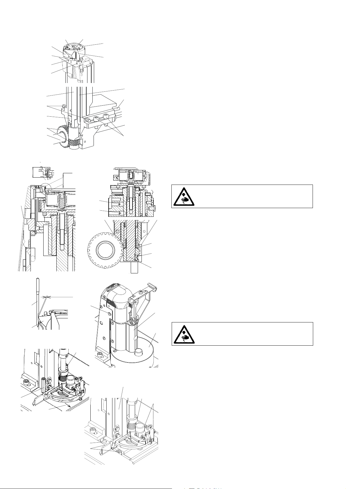
The hook (1) is mounted on the shaft (2) and is driven by the
gear (3) from the shaft (4).
The shaft of the hook (2) is mounted on the top in a sliding
bearing and, on the bottom, in a needle bearing.
The hook is provided with a lever (6) which is tilted when
removing the bobbin (7). The protecting sheet (8) protects
against the collision of the needle with the hook point. The
bobbin case opener (9) is driven by the eccentric (10) on the
shaft (2).
The lubricating tube (11), on which a lubricating wick is
fastened in the tube (12), feeds oil for lubricating the sliding
bearing (5) of the eccentric (10) and the hook path.
The screws (13) serve for taking up the clearance of the gear.
The screws (14) fasten the post to the bedplate.
The lubricating felt (15) is connected by the wick (16) with the
main lubricating system and serves for lubricating the gear (3).
A
1
A
3
4
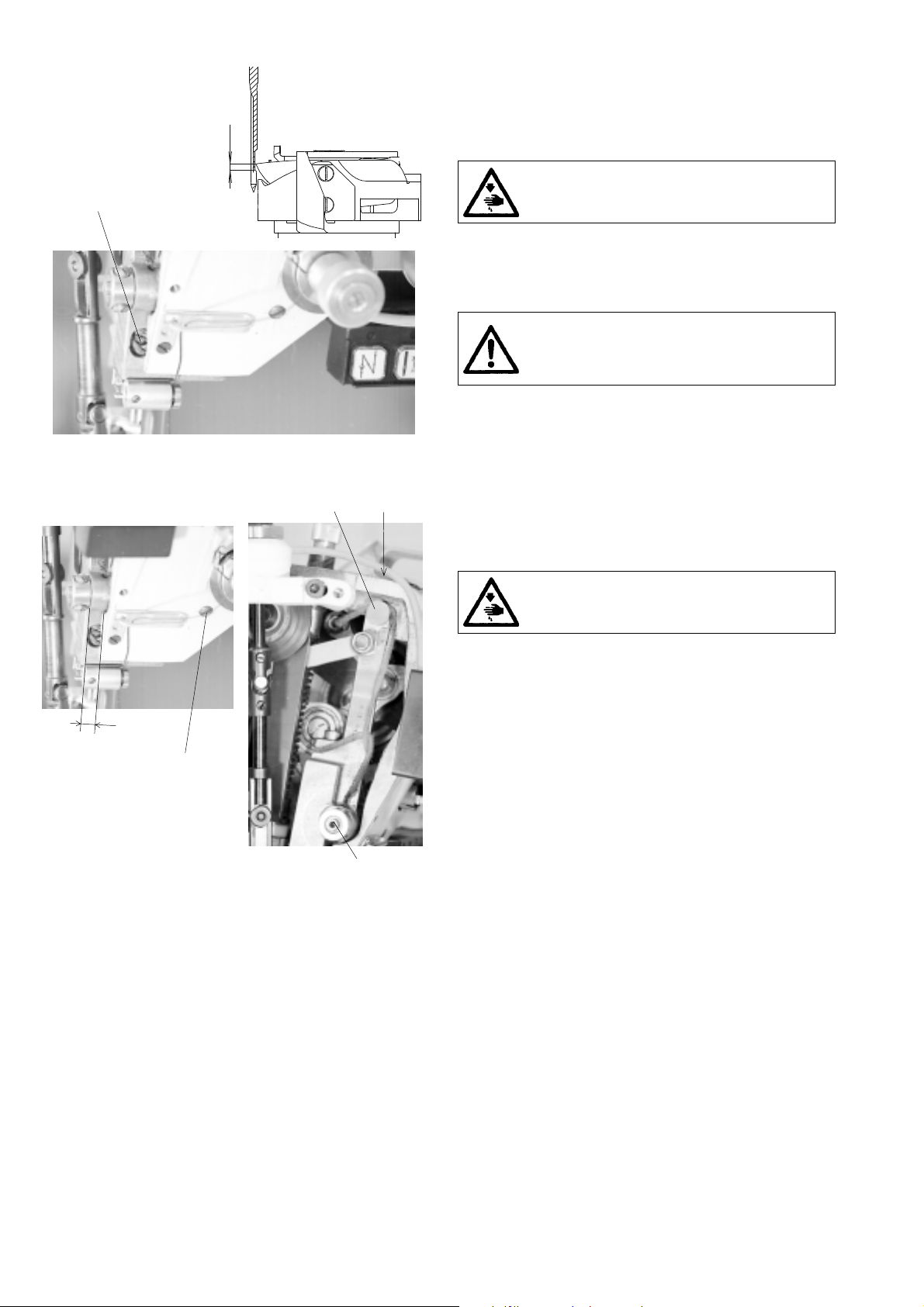
3.1.2 Height setting of the hook
The designated distance A should be 6.1 mm.
Caution! Danger of injury!
Switch off the main switch ! Before starting the
setting operation, wait until the motor stops!
- Remove the guard (1).
- Loosen both screws (2).
- By turning the screws (3 and 4), set the required distanceA.
After having set it, tighten carefully the screws.
- By axial shifting of the gear wheel (5), set the axial clearance
5
2
6
in such a way that this clearance is the least possible, but
sufficient for turning easily the hook.
- Tighten carefully the screws (2). Caution ! One of these
screws must bear on the flat of the shaft 6).
3.1.3 Setting the distance of the hook from
the needle
max. 0,1
2
7
1
5
11
5
9
10
6
The hook point (1) is set up to the maximum distance of 0.1
mm from the bottom of the needle recess (2). For the sewing
categories 1 and 2, the needle size 100 is set, for the sewing
3
category 3, the needle size 140 is set.
4
- Remove the covers (3) and (4).
- Screw out the screws (5), and slide the plate (6) out.
- Loosen the screw (7).
- Loosen only one screw (9).
- Loosen the screws (10) and tighten them only slightly.
- Shift the hook post (11) at the determined distance between
the needle and the hook point.
- Tighten carefully the screw (9) (be sure not to damage the
threads!)
- Tighten duly the screws (10).
- Check up the setting using a narrow strip of thin paper and
proceed to the eventual correction of setting.
Caution! Danger of injury!
Switch off the main switch ! Before starting the
setting operation, wait until the motor stops!
10
9
2
2
1
57
3
o
205
4
~ 0,5
6
3.1.4 Angular setting of the hook (timing)
The hook is to be angularly set in such a way that the hook
point (1) is opposite the needle at the moment, when the
needle shifts by 2.5 mm from its bottom dead center. This
corresponds to the 2O5° on the scale of the handwheel (3).
Caution! Danger of injury!
Switch off the main switch! Before starting the
setting operation, wait until the motor stops!
- Remove the throat plate.
- Turn the handwheel (3) to the 2O5° and fix it with the screw
(4) which is component part ot the accessory of the machine
(tighten it carefully).
- Loosen the screws (5).
- Turn the hook into the required position.
- Set up the distance of about 0,5 mm between the gear wheel
(6) and the pin (7).
- Tighten to the maximum the screws (5).
3.1.5 Protection of the needle and of the hook point
The protecting sheet (1) is to be set up in such a way that the
clearance between the protecting sheet and the needle (2) is
the least possible.
2
5
3
4
1
6
3
- Remove the throat plate.
- In deforming the protective sheet (1) set the required play
between the sheet and the needle (2). After having introduced
a suitable screwdriver between the protective sheet and the
hook body (3) we shall reduce the play by levering, in
applying the pressure on the protective sheet in the sense
of the arrow (4), we shall increase the play.
- Check up the protecting effect in pushing against the needle
in the sense of the arrow (5). The hook point must not catch
the needle. If so, set up the protecting effect, correct
eventually the setting of the distance of the hook point
from the needle according to the paragraph 3.1.3.
3.1.6 Setting of the bobbin case opener
The bobbin case opener (1) is to be set in such a way that, at
the moment when the opener is in its dead centre, there would
be a clearance A between the opener (1) and the projection
(2), whereas the finger (3) bears on the projection (4), A =
0.7 mm for the sewing category 1 and 2, A = 0.3 mm for the
sewing category 3.
4
Caution ! Danger of injury!
Switch off the main switch! Before starting the
setting operation, wait until the motor stops!
Caution ! Danger of injury!
Switch off the main switch! Before starting the
setting operation, wait until the motor stops!
- Remove the sheet guard of the hook post.
1
A
2
5
o
295
- On the handwheel (5), set the angle of 295° (the hook is in
its dead centre).
- Loosen the screw (6).
- Turn the eccentric (7) in such a way that the required
clearance between the elements (1) and (2) is attained.
- Set the height of the eccentric (7) in such a way that it is in
its highest position in retaining the minimum clearance
between the slide (8) and the fork (9).
- Tighten duly the screw (6).
78 69
3
6
7
5
1
0,4
11
8
3
4
1
9
2
15
o
10
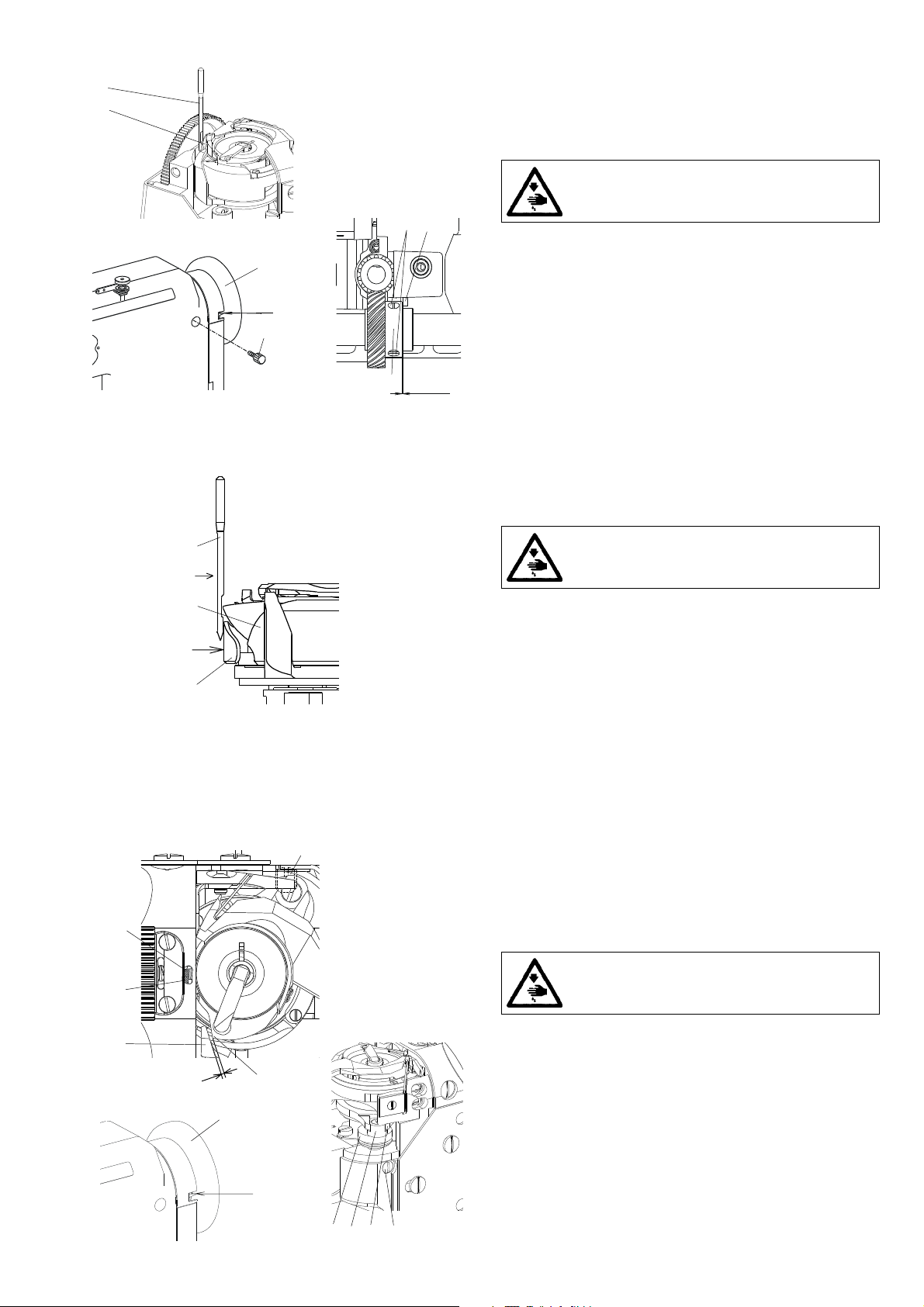
3.1.7 Setting the regulation of the hook lubrication
By turning the lubricating tube (1) in the sense of the arrow
(2), the size of the contacting surface between the wick (3)
and the felt insert (4) is regulated. In this way, the speed of the
capillary lift of oil into the felt insert (5) is influenced, from
which oil is wiped on the surface (6) and is driven by centrifugal
force into the hook path (7).
Setting of full lubrication
- Turn the screw (8) into the position (9).
Setting of limited lubrication
- Turn the screw (8) into the position (10).
After having ended the regulation, set the height of the
lubricating
tube (1) at 0.4 mm from the eccentric (11).
1
2
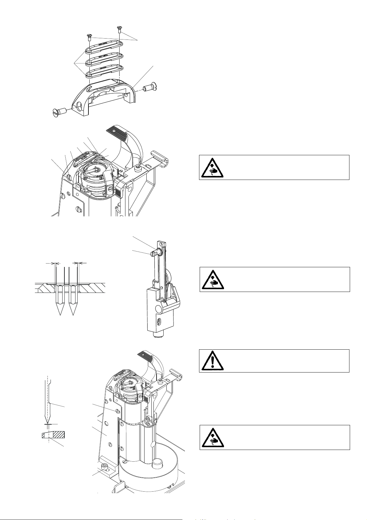
3.1.8 Replacement of the hook
Caution! Danger of injury!
Switch off the main switch ! Before starting the
setting operation, weit until the motor stops!
3
- Remove the throat plate and the trimming knife.
- Unscrew the screws (1) and remove the gib (2).
4
5
4
1
3
5
2
- After having suitably turned a bit the hook, remove the
bobbin case (3).
- Unscrew thorougly the screw (4).
- Remove the body of the hook (5) upwards.
- When mounting, the procedure is inverse.
3.1.9 Setting the gear
The mutual angular orientation of the gear wheel (1) relative
to the gear wheel (2) should ensure the accessibility of the
screw (5) at the moment when the hook point (3) comes to lie
opposite the needle (4). The wheel (2) is to be set with its gear
rim symmetrically to the centre of the gear wheel (1). The
clearance between the gear wheels is to be the least possible.
Caution ! Danger of injury!
Switch off the main switch! Before starting the
setting operation, wait until the motor stops!
~0,5
205
7
- Set the angle of 2O5° on the handwheel (6) and lock it with
the screw (7).
- On the removed post of the hook (8), according to the pa-
6
8
o
9
10
9
10
ragraph 3.1.10, the hook point (3) is to be turned a bit
according to the illustration.
- Turn the gear wheel (2) into the suitable position and insert
the post of the hook into the machine according to the
respective arrows. Check up, whether the screw (5) is
accessible and, if not, repeat the procedure.
- Set the the distance of the hook from the needle according
to the paragraph 3.1.3.
- Set the precise angular displacement of the hook according
to the paragraph 3.1.4.
- Loosen the screw (10) and tighten them slightly.
- Set the clearence in the gear in turning the screws (9). Check
up, whether the gear has a clearance during the whole
revolution of the hook. Turn the handwheel step by step by
15° and, with each step, grasp the hook and try, if there is an
angular dead travel. Tighten carefully the screws (9).
- Tighten duly the screws (10) and try anew the clearance of
the gear.
4
3.1.10 Dismantling of the hook post
3
2
9
1
5
6
7
11
5
6
When dismantling the post (1), the supplies of lubricating oil
are to be disconnected first, the fastening screws unscrewed
and, thereafter, the post is removed.
Caution ! Danger of injury!
Switch off the main switch! Before starting the
setting operation, wait until the motor stops!
- Remove the covers of the post.
- Unscrew the screw (2).
- Push the lubricating tube (3) downwards into the post.
- Disconnect the hose with the wick.
- Screw out the screw (4) of the lever (8) on the shaft of the
trimming knife (9). Loosen the screw (10), turn the lever (8)
as indicated by the arrow, and take it out of the shaft.
- Loosen the screws (11) of the microswitch holder.
- Loosen only one screw (5).
- Unscrew the screws (6).
- Shift the post in the sense of the arrows and remove it out
from the machine.
- When mounting it, proceed inversely. Make sure that the
wicks in the tubes are in contact with the other wicks leading
oil into the box (7).
10
9
8
8
4
3
3.2 Needle and thread mechanism
7
3.2.1 Description
The take-up lever (1) is mounted in ball bearings, both at the
spot of its suspending on the connecting rod (2) and in the
mounting on the loop (12). The take-up lever is of aluminum
and is provided with a stuck-in eye for two threads. The
connecting rod (2) is mounted on the eccentric pin (3), by
means of which the thread mechanism is adjusted for a big or
a small hook. The needle bar holder (4) is mounted through
the pin (5) in a rotating way in the arm (6). In its top part, the
holder is guided by the guide pin (7). The movement for the
needle feed is given to it by the connecting rod (8) driven by
the feeding shaft (9). The connecting rod (8) is mounted by
eccentric pin (13) with needle bar holder (4).
The connecting rod (10) of the needle bar (11) on the loop
(12) is mounted in a ball bearing and it is slidingly mounted
on the needle bar carrier. The mechanism is lubricated by means
of a central-wick lubricating system.
12
10
11
2
13
1
9
4
6
5
3.2.2 To check the handwheel angular adjustment
2
3
5
4
1
The handwheel (5) must be situated in its precise position
relative to the needle and thread mechanism. This position is
given by a pin (2), which locks the connecting rod of the
needle rod (1) through a hole in the arm (3). In this position,
the indicator (6) of the handwheel must show O. The position
is fixed by the handwheel screw (4) contacting a small flat
surface provided on the upper shaft.
The correct adjustment of the angular position has been car-
ried out at the producers.
o
0
Caution ! Danger of injury!
Switch off the main switch! Before starting the
setting operation, wait until the motor stops!
6
5
3.2.3 Height setting of the needle bar
At the moment, when the hook point passes around the needle,
the upper edge of the needle eye must be about 1 mm below
the hook point. In an opposite case, it is necessary to set the
height of the needle bar as follows:
1
1
- Remove the front guard.
- Loosen the screw (1) of the needle bar carrier
- Set the correct height of the needle bar and tighten anew
the screw (1).
Caution ! Danger of injury!
Switch off the main switch! Before starting the
setting operation, wait until the motor stops!
Caution !
An incorrect setting of the needle bar height may
cause the striking of the hook point against the
needle.
34
A
1
3.2.4 Side setting of the needle bar holder
The correct position of this holder is in such case, when the
needle bar is lined up with the presser-foot bar. The needle bar
holder can be set as follows:
Caution! Danger of injury!
Switch off the main switch! Before starting the
setting operation, wait until the motor stops!
- Loosen the screw (1) of the pin (2).
- Loosen the screw (3) of the guide pin (4).
- In shifting the pin (2) set the needle bar holder on the
measure A = 7.5 mm (distance of the front faces of the
arm and of the needle bar holder) /at the same time the pin
(4) shifts/.
- The guide pin (4) is to be set in such a way that the needle
bar holder moves easily.
- Tighten the screws (1 and 3).
2
6
3.3 Throat plate and its post
3
2
6
5
4
5
6
1
3
2
1
3.3.1 Description
The throat plate (1) is equal for all categories of sewing. In the
throat plate there is fixed by means of two screw (3) the
exchangeable throat plate insert (2). Each category of sewing
has its own insert of the throat plate which differ one from
another by the length and width of the piercinghole.
3.3.2 Mounting and removing the throat plate and
its insert
When mounting the throat plate (1), the finger of the hook (2)
must fit into the recess (3) of the throat plate. When demouting
or replacing the throat plate insert (4), both screws (5) are to
be unscrewed and the insert romoved.
Caution! Danger of injury!
Switch off the main switch! Before starting the
setting operation, wait until the motor stops!
- Turn slightly the finger (2) in the sense towards the throat
plate (1).
- Place the throat plate (1) and screw in the screws (6).
- Place the insert (4) and screw in the screws (5).
2
1
E
E
The directions E" between the needle and the edge of the
piercing hole must be the same both at the beginning and at
the end of the needle feeding.
- According to the table 11.2, limit for the respective sewing
- Set the maximum stitch length.
- Loosen the screw (1) of the eccentric of the needle bar
- By turning the eccentric (2), set the required distance E".
- Tighten up the screw (1) and check up the setting.
the direction of sewing (fine setting)
Caution! Danger of injury!
Switch off the main switch! Before starting the
setting operation, wait until the motor stops!
category the maximum stitch length (see 3.5.2.4).
holder.
Caution!
A faulty setting may cause bending or breaking of
needles against the throat plate insert.
3.3.4 Side setting of the throat plate post
3.3.3 Setting the needle (the needle bar holder) in
3
4
A
1
2
5
The post of the throat plate (1) is to be side set in such a way
that the axis of the hole in the insert of the throat plate (2) is at
the distance A = 0.1 mm to the right from the axis of the
needle (3).
Caution! Danger of injury!
Switch off the main switch! Before starting the
setting operation, wait until the motor stops!
- Loosen the screws (4 and 5) (from the rear side of the post
as well).
- Shift the post (1) in the sense required for attaining the
distance A = 0.1 mm.
- Tighten the screws (4 and 5) and check up for the correct
setting.
7
3.4 Thread tensioners and limiter
45
2
3
7
6
11 8
21
10
9
13
12
3.4.1 Description
2
1
3
1
The main tensioner (1) serves for creating the tension of the
threads when tightening the stitch. The auxiliary tensioner (2)
reduces the risk of pulling out of the thread after the thread
trimming when removing the sewn material, when the thread
is passed through this material and when the main tensioner
is relieved. The main tensioner is relieved by the mechanism
controlled by the shaft of the presser foot lifting (3), on which
the lever (4), is mounted which shifts the prop (5), which
pushes the metal sheet lever (6). This lever shifts the pin (7)
and this pin pushes onto the washer (8) and relieves the spring
(9).
With the machines provided with a thread trimming device,
the main tensioner (1) is relieved as well when switching on
the electromagnet (10), when its armature (11) pushes against
the lever (6). The mechanism of the adapting spring (12)
maintains the thread in its tensioned state when passing
through the hook. The thread limiter (13) limits the length of
the thread fed by the take-up lever when moving from the
upper to the bottom dead centre to get a controlled passing
of the thread through the hook.
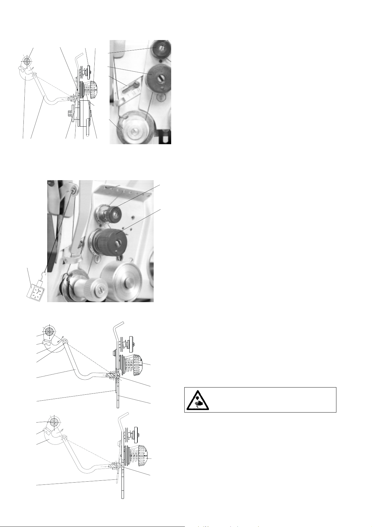
3.4.2 Setting the tension of the main and auxiliary
tensioners
The tension of the main thread tensioner is regulated by means
of the nut (1). The force of tensioning the thread is measured
by the dynamometer (2) as it is shown on the illustration. The
size of this force differs according to the category of sewing
and is indicated in the par. 12.2.
The tension of the auxiliary tensioner is regulated using the
P
nut (3). It should be the least possible, but sufficient for
unthreading the thread from the sewn material when removing
the sewn material from the pressing element without leaving
the tensioner.
3.4.3 Setting the tensioning mechanism of the
6
8
4
9
7
5
The nut (1) must be screwed off in such a way that the metal
sheet lever (2) bears on the plate (3) and, at the same time, the
lever (4) is not limited by the prop (5) in its rotation. The lever
(4) must be fixed against the shaft (6) in such a way that,
when the presser foot is in its lowest position, the nut (1)
bears on the metal sheet lever (2) with its minimum clearance.
1
2
6
3
- Unscrew thoroughly the nut (7) and loosen the screw (8).
- Put in one line the axis of the shaft (6), the axis (9) and the
8
4
7
1
2
- Unscrew the nut (1), until the metal sheet lever (2) strikes
- Screw in the nut (7) almost to the stop.
- Remove the sewn material and lower the presser foot.
- Turn the lever (4) in the sense of the arrow up to the stop.
- Return the lever (4) a bit back and tighten the screw (8).
main tensioner
Caution ! Danger of injury!
Switch off the main switch! Before starting the
setting operation, wait until the motor stops!
axis of the spherical surface of the nut (1).
against the plate (3). However, the lever (4) must rotate freely
in the sense of the arrows in both senses.
8
3.4.4 Setting the adapting spring
5
11
1
6
C
87
10
4
32
1
F
A
B
9
The mechanism of the adapting spring is to be set up in such
a way that, when uscrewing the nut (1) up to the stop to the
washer (2), the conical spring (3) remains under the tension
which is set by shifting the adjusting ring (4) locked by the
screw (1O). The angular setting thereof is to be done in such
a way that the angle A = 45°. The axial setting is to be done
in such a way that the plate (5) and the plate (6) are at the
mutual distance equal to the measure C= 3 mm. The washer
(7) is to be oriented in such a way that the distance B = 1 to
1.5 mm. The bushing (8) is to be oriented in such a way that
the adapting spring (9) is tensed up by 90° from the free state.
Caution! Danger of injury!
Switch off the main switch! Before starting the
setting operation, wait until the motor stops!
- Unscrew the nut (1) up to the stop towards the washer (2).
- Loosen the screw (10), push heavily the ring (4) against the
washer (2) and tighten the screw (10).
- Mount the mechanism of the adapting spring into the
machine in such a way, so that the pieces (5 and 6) are at
the distance C = 3 mm, set the angle A = 45° and tighten
the screw (11).
- Turn the washer with the nose (7) in such a way that the
distance B = 3 mm is attained.
- Put the screwdriver into the slit in the bushing (8) and turn
it in counterclockwise direction, until the spring (9) touches
slightly the nose of the washer (7). Turn then still the bushing
(8) by 1/4 revolution.
- Tighten the nut (1). In this way, the whole mechanism im-
mobilizes.
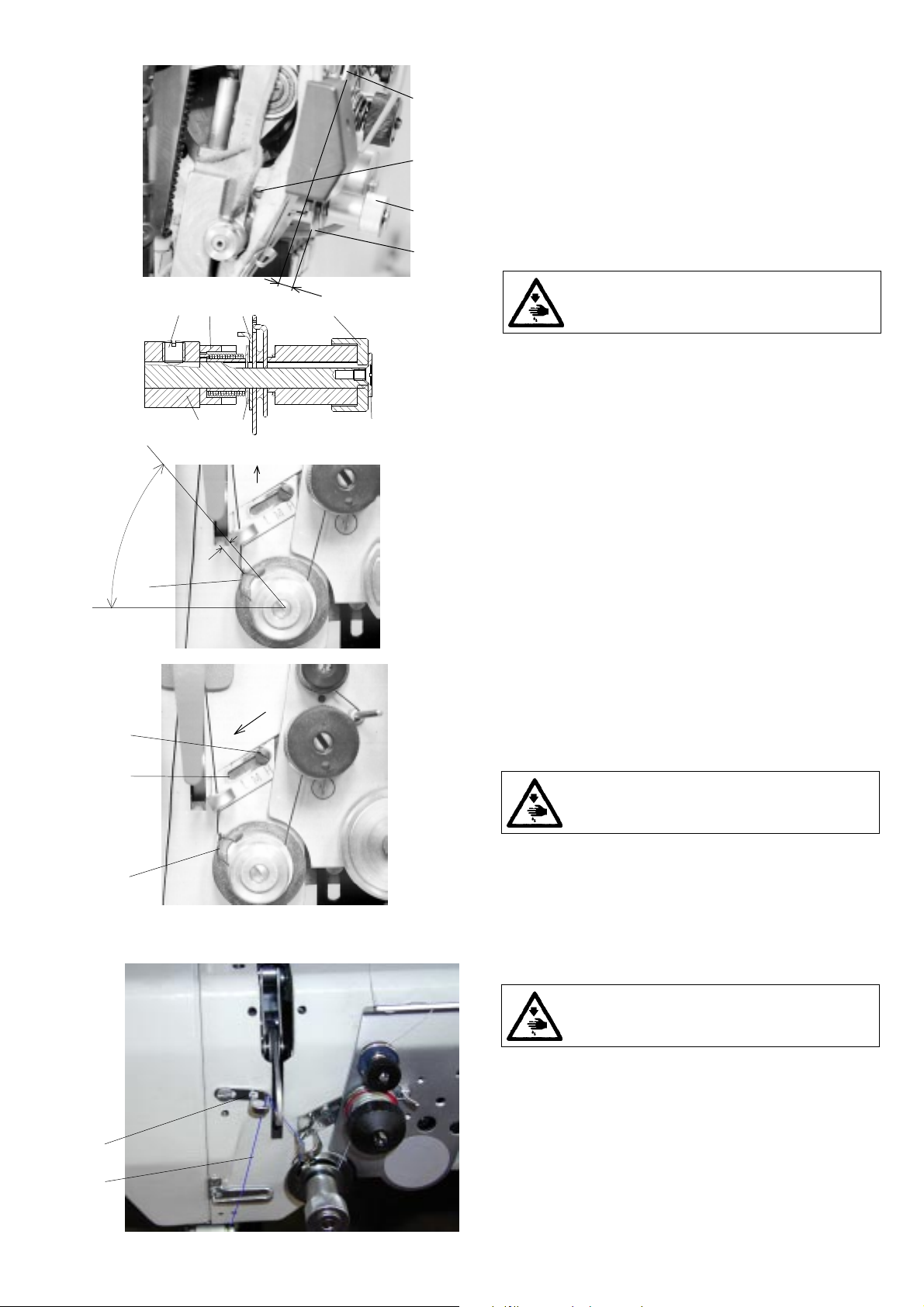
3.4.5 Setting the thread limiter
The thread limiter is to be set in such a way that, when sewing
and passing the thread through the most distant point of the
hook, the spring (2) shifts by about 3/4 to 1 length of its total
length. This means that the thicker will be the sewn material
and the longer will be the stitch length, the more will be the
limiter shifted in the sense of the arrow and inversely. Under
3
1
2
standard sewing conditions, the thread limiter is set in its
tested positions depending on the sewing category in
accordance with the chapter 12.
Caution! Danger of injury!
Switch off the main switch! Before starting the
setting operation, wait until the motor stops!
- Tighten the screw (3).
- Set the thread limiter (1) in such a way that the screw (3)
is situated above some letter according to the chapter 12.
- Tighten the screw (3).
3.4.6 Setting the additional thread limiter
The new version of the machine is equipped with an additional
thread limiter for improving the stitch uniformity. To set it,
proceed as follows:
Caution! Danger of injury!
Switch off the main switch! Before starting the
setting operation, wait until the motor stops!
- Set the stitch length to the required value.
- Sew an approximately 5 cm long seam along the edge of
sewn work, switch off the machine, and tilt away the hook
cover.
1
2
- Rotate the handwheel until the thread taken up by the hook
will be stretched across its bottom, i.e., across the full
diameter of the hook.
- Adjust the position of the additional limiter (1) so as to obtain
an almost complete stretching of the thread (2) at that
moment, as shown in the drawing.
- Sew next stitch and check the adjustment.
9

15
13
12
3
1
3.5 Feeding mechanism of the needle feed and of
the lower feed wheel
2
14
4
5
6
8
9
7
3.5.1 Description
The feeding mechanism is formed by the leverage (1) which
is driven from the main shaft through the eccentric with
connection rod (2). The feeding motion is transmitted by the
shaft (3) on the clutch of the bottom feed (7).
The engaging and the disengaging function of the clutch (7)
is controlled from the lower shaft (8) through the eccentric
with the connecting rod (9) and through the wedge coupling
(10). The feeding movement is transmitted by the shaft (11)
through the chain transmission (12) onto the wheel feeder
(13). The stitch length is set by the knob (14) through the
leverage (15) to the feeding mechanism (1).
90
11
10
3.5.2 Stitch length mechanism
3.5.2.1 Setting the upper eccentric
6
The eccentric (1) must be set in its angular position in such a
1
way that the horizontal component of the needle motion is in
a phase delay from the vertical component of this movement.
This refers to the angle of 90° on the handwheel (2), when the
3
setting stick (3) is engaged into the eccentric (1) and leans
4
from above against the feeding shaft (4).
2
Caution! Danger of injury!
Switch off the main switch! Before starting the
o
- Set the angle 90° on the handwheel (2) and lock it with the
screw (5) which is included in the accessory of the machine
(tighten it carefully).
5
D
C
- Insert the setting stick (3) into the hole in the eccentric (1)
and prop it against the feeding shaft (4).
- Shift axially the eccentric on the shaft up to its extreme
position to the right or to the left and place it in the medium
position.
- Tighten the screws of the eccentric (6) to the utmost (one
screw first and, in turning a bit the handwheel, another screw
too).
setting operation, wait until the motor stops!
1
3.5.2.2 Setting the prop
In this machine with a wheel feed, the prop (1) is mounted in
the pits (A and C) as per the drawing.
B
A
3.5.2.3a Forward and rearward stitch length
distribution (rough)
The cam (1) is to be set at the respective angle in such a way
that the stirrup (6) is oriented in such a position, so that the
3
2
9
1
678
o
0
4
connecting rods (7 and 8) are in a line with a thoroughly
screwed in knob (9) and with turning the handwheel at 0°.
This setting can be done only after having set the top eccentric
according to the paragraph 3.5.2.1.
Caution! Danger of injury!
Switch off the main switch! Before starting the
setting operation, wait until the motor stops!
- Set the zero stitch /screw in the knob (9) to the bottom of
the cam (1)/.
- Set the angle 0° on the handwheel and lock it with the screw
(4).
- Turn the screw (3) in the respective sense in such a way that
the connecting rods (7 and 8) are in a line and tighten the
screw (2).
10

3.5.2.3b Forward and rearward stitch length
distribution (fine)
When setting the maximum length of the stitch, the forward
and the rearward stitch length must be equal with the maximum
error of ± 5 %. This setting can be done only after having set
the needle feed (par. 3.5.3) and the wheel feed (par. 3.5.4.1.2).
3
2
- Set the maximum stitch length .
- Place a suitable material under the presser foot and mark
therein the forward and the rearward stitch length.
- With an unequal length of the stitch, proceed to the cor-
rection of setting by turning the screws (2 and 3). When
tightening the screw (3), the forward length of the stitch is
shortened and inversely. When tightening the screw (2), the
forward stitch length is lenghtened. Tighten the screw (2).
Caution! Danger of injury!
switch off the main switch! Before starting the
setting operation, wait until the motor stops!
3.5.2.4 Setting the control knob (including the stitch
length limitation).
The control knob (1) is to be set up in such a way that, when
turning it in counterclockwise sense up to the stop, the
maximum stitch length valid for the given sewing category is
attained (cat. 1: 3 mm, cat 2: 5 mm, cat. 3 : 5 mm). The scale of
the control knob is to be oriented in such a position, so that
the scale end corresponds to the maximum stitch length,
excepting the first sewing category, where the stitch length of
1
2
3
4
5
the indicator is 3 mm.
Caution! Danger of injury
Switch off the main switch! Before starting the
setting operation, wait until the motor stops!
- Screw in the screw of the control knob in such a way that the
ball of the screw (3) bears on the seat of the cam (4).
- Loosen the screw (5) and turn the control knob in the
clockwise
direction, until the pin (6) of the knob (1) bears on the pin
128
5
6
7
(7). Tighten firmly the screw (5).
- Turn the knob in the counterclockwise direction up to the
stop,
when the pin (6) of the knob (1) bears on the pin (7).
- In a sewing test check up the length of the stitch, if this
corresponds to the maximum stitch length valid for the given
sewing category.
- If the stitch is longer, loosen then the screw (5) and turn the
knob in the clockwise direction and inversely. Tighten firmly
the screw (5).
- Insert a screwdriver into the hole (8) of the scale (2) and
adjust the scale in such a way that the maximum length on
the scale is against the marking of the stitch length on the
machine arm.
- For the sewing category 1, set the control knob (1) on the
stitch length of 3 mm and check it by a sewing test.
- Loosen the screw (5) and turn the control knob (1) in the
counterclockwise direction, until the pin6) of the knob (1)
bears on the pin (7). Tighten firmly the screw (5).
- Put a screwdriver into the hole (8) of the scale (2) and adjust
the scale in such a way that the value of the stitch length on
the scale against the marking on the arm is 3 mm.
11

13
3.5.3 Setting the needle feed (rough)
In the lower dead point of the needle bar (needle), the distances
A between the needle and the walls of the needle aperture in
the throat plate insert must be alike.
Caution! Danger of injury!
Switch off the main switch! Before starting the
setting operation, wait until the motor stops!
- Set the needle bar to its lower dead point /corresponding to
the anle of 180° on the hand wheel (1)/.
- Fix the position by tightening screw (2).
- Loosen screw (3) and set the distances A. Then retighten
screw (3).
180
A
1
o
2
3
A
3.5.4 Lower feed wheel
3.5.4.1 Feeding clutches
3.5.4.1.1
The feeding clutch is formed by the clutch cover (1) driven
3
2
8
9
10
1
7
11
5
6
4
12
from the connecting bar (2), by the clutch star (4) driven from
the connecting rod (3) and by the carrier plate (5) firmly
connected with the shaft (6). Of the clutch give the connecting
rods (2 and 3) an opposite direction swinging movement. The
clutch is coupled by means of the wedge (7) on the connecting
rod (8) through the eccentric (9) which is placed on the lower
shaft (10).
In the position, when the wedge is disengaged, the star (4)
is shifted out from the frictioning engagement with the lining
of the carrier plate (5) by means of the spring washer (11). The
plate (5) lining is then pushed by means of a flat profiled
spring (2) against the cover of the clutch (1).
In the position, when the wedge is disengaged, the star (4)
is pushed against the plate (5) lining and, at the same time,
the friction connection with the cover of the clutch (1) is
disconnected. Within a short instant, when engaging and
disengaging with the carrier plate (5), there are in a friction
engagement both the cover (1) and also the star (4), namely in
the dead centre of the connecting rods (2 and 3). The setting
of the change-over of clutches is done by tightening or by
loosening the nut (13).
Description
1
4
4.1
3
5
1/2
1/2
3.5.4.1.2 Setting the lever of the second step of
feeding (angle, position).
The lever of the second step (1) must be set in such a way
that, in the bottom dead centre of the needle, a part of the
clutch disk (2) halves the angle between the screws (3). The
6
8
5
2
A
3
2
1
4
pin screw (4) is mounted into the position (4.1 - corresponds
to the maximum stitch length of 5 mm).
Caution! Danger of injury!
Switch off the main switch! Before starting the
setting operation, wait until the motor stops!
Lever (1) displacement.
- Loosen the screw (6).
- Set the maximum stitch length.
- Set the angle 180° on the handwheel.
- Unscrew the screw (5) and put the needle shank in its hole.
- Turn the lever (1) until the needle drops into the clutch disk (2).
- Side set the lever (1) to the measure A= 0.5 to 1 mm.
- Tighten the screw (6).
- Screw in the screw (5) and seal it with the Loctite cement.
12

244
1
o
45
3.5.4.1.3 Setting of the lower eccentric
The rotation of the eccentric (3) must be delayed in phase by
1/4 revolution against the rotation of the eccentric of the stitch
length. This corresponds to the angle of 244° on the handwheel
(1), when the setting pin (4) is put into the eccentric (3) which
is in contact with the indented belt (5).
2
- Set 244° on the handwheel (1) and lock it with the screw
(2), which is included in the accessory of the machine
(tighten it carefully).
- Put the setting stick (4) into the hole in the eccentric (3) and
6
3
A
1
prop it from below against the indented belt (5).
- Set eccentric (3) axially.
- Tighten it the utmost the screws of the eccentric (6).
- By means of the handwheel, turn the eccentric (3) into the
marked position and check in this position the clearance
A = 0.05, proceed eventually to its correction by a new
side setting of the eccentric.
3.5.4.1.4 Setting the engagement and
Caution! Danger of injury!
Switch off the main switch! Before starting the
setting operation, wait until the motor stops!
disengagement of the clutches
90
o
2
The nut (7) is to be side set in such a way that the shifting of
the clutches is done at the moment when the clutch disks (3)
do not move, which means, when they are at the dead center
of their oscillating movement. This corresponds to the angle
90° on the handwheel.
Caution! Danger of injury!
Switch off the main switch! Before starting the
setting operation, wait until the motor stops!
- Loosen the screws of the indented pulley of feeding and
shift it to the left.
- Set the maximum stitch length.
- Set the angle 90° on the handwheel and lock it with the
screw (2). which is included in the accessory of the machine
(tighten it carefully).
- Loosen three screws (6) in the nut (7) and unscrew it by
2 mm to the left.
- Tighten slowly the nut (7), until it strikes against the axial
bearing (9). (At this moment, the tightening moment
increases in jumps) and tighten the screws (6).
- Set the the handwheel on 85° and push the backtacking
lever, the feeder is to turn against the movement of the
needle. Set then the handwheel on 95°, the feeder is to be
turned in the sense of the needle movement. If not being
7
6
9
3
so, correct the side setting of the nut (7). When the clutches
shift too soon, turn a bit the nut (7) to the right and inversely.
- Tighten the screws (6).
- Return the indented pulley in its original place according to
the paragraph 3.6.2.
13

3.5.4.2 Wheel feeder and its post
3.5.4.2.1 Height setting of the feeder and tension-
1
The wheel feeder (1) is to be set in such a way that the points
X
1
of its teeth overtop the throat plate by X= 0.2 to 0.4 mm.
When sewing soft and thick materials, it is necessary to
increase the value X, until a good quality of feeding is
attained, but only to the measure of not deteriorating the
beginning of sewing after the carried out thread trimming.
With every correction of the teeth height, the tension of the
chain (2) is to be corrected.
4
- Loosen the screw (3).
- Loosen the screw (4).
5
- Loosen or tighten the screw (5) and push simultaneously
with finger the feeder (1) downwards, until the required
height of the teeth X of the wheel feeder is attained.
- Tighten then still the screw (5) by 45° (1/8 revolution).
- Tension the tensioner (6) up to the stop. Be careful in side
shifting it to the centre of the chain. Tighten the screw (3).
- Loosen the screw (5) by 45° (1/8 revolution), into its original
position. In this way, the optimal clearance of the chain
transmission is attained.
- Tighten the screw (4).
- Correct the set height of the top roller according to the
par. 3.5.5.
3
ing of the chain
Caution! Dangere of injury!
Switch off the main switch! Before starting the
setting operation, wait until the motor stops!
6
2
14

3.5.4.2.2 Replacement of the feeder
For the replacement of the wheel feeder (change of the wheel
feeder according to the machine setting - see par. 12.2 - setting
of the machine - feeder - pitch of the teeth).
3
4
- Unscrew the screws (1) and remove the throat plate (2).
5
6
9
7
1
2
2
- Unscrew the guard (7).
- In pulling upwards (securing by a spring), pull out the feeder
8
(3) with the guide (4).
- Replace the feeder (3).
- Insert the feeder with the guide into the groove of the holder
(5).
- Mount the throat plate (2) and tighten up the screws (1).
- Check up, if the spring (6) pushes the guide (4) with the
feeder (3) against the wheel (8).
- In the opposite case, loosen the screws (9),tense up the
spring in such a way,so that the guide (4) with the feeder (3)
is pushed against the wheel (8) and tighten the screws (9).
- Mount the guard (7) and tighten the screws.
Caution! Danger of injury!
Switch off the main switch! Before starting the
setting operation, wait until the motor stops!
3.5.5 Setting the top roller (pressing force, height)
When lowering the top roller (1), set the clearance A between
the feeder (5) and the top roller to the maximum of 0.2 mm.
Set the pressing force of the top roller (1) so as to avoid the
slippage of the sewn material when feeding it.
Method of setting the height of the top roller:
- Lower by hand the presser bar (3) with the top roller (1)
above the wheel feeder (5).
4
3
- Loosen the screw (4) and set the required value A (0.2 mm).
- Tighten the screw (4).
Setting the force of the top roller (1).
- In screwing in the screw (2),the force of the top roller is
increased and inversely.
1
5
A
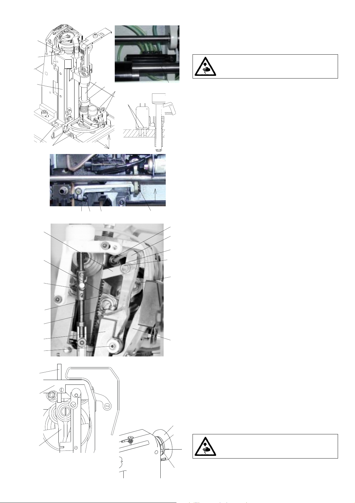
3.6 Feeding mechanism of the top roller
3.6.1 Description
The starting movement for the drive of the top roller feeder is
the bottom feeding shaft. From this shaft, the movement is
transmitted by the indented belt (1) onto the top feeding shaft
(2). A component part of the transmission by indented belt is
the pulley (3), the tensioning roller (4), the roller (5) and the
pulley (6). Starting from the shaft (2), the movement is further
transmitted through the friction wheels (7 and 8) of drive
conversion unit onto the articulated shaft (9). From this
articulated shaft, the movement is transmitted by a cone
transmission, situated in the holder (10), onto the feeder wheel
(11). The drive conversion unit serves for compensating the
differences in feeding by the driven top roller and by the lower
feed wheeler. By turning the screw (12), the change of the
gear speed ratio is attained. After having set in accordance
with the par. 3.6.6, the screw (12) in the holder (13) is to be
locked by the nut (14). The pressure of the friction wheels (7
and 8) is ensured by the compression spring in the shaft (2).
To avoid a complete pushing out from the arm, the shaft is
locked by a stirrup ring (17). The shaft of the friction wheel (8)
is mounted in the screw (12) on needle bearings. The
articulated shaft (9) contains two joints (15) and a telescopic
part (16). Both these
of the top roller.
elements secure the lifting and the tilting
15
16
15
10
11
178131214
62
7
5
9
1
4
3
15

6
2
1
5
3
4
3.6.2 Side setting of the indented lower pulley
The pulley must be set up in such a way that the belt passes
through the centre of the passing hole in the bedplate. The
setting operation is to be done as follows:
Caution! Danger of injury!
Switch off the main switch! Before starting the
setting operation, wait until the motor stops!
- Loosen the screws (1) of the pulley (2).
- Loosen the screw (3) of the tensioning roller (4)
- Set the pulley (2) in such a way that the belt (5) passes
through the centre of the passing hole in the bedplate (6).
- Tighten the screws (1).
- Set the tensioning roller (4) axially in such a way that the
belt (5) is set at the middle of the tensioning roller (4).
- Set the tensioning roller (see par. 3.6.4).
- Tighten up the screw (3) of the tensioning roller (4).
5
1
2
3.6.3 Side setting of the indented upper pulley
The pulley is to be set in such a way that the indented belt is
not crossed and the pulleys are in line. The setting thereof is
to be done as follows:
Caution! Danger of injury!
Switch off the main switch! Before starting the
setting operation, wait until the motor stops!
- Loosen the screws (1) of the pulley (2).
- Set the pulley (2) in such a way that the distance of 5 mm
is attained in accordance with the illustration.
- Tighten the screws (1).
3.6.4 Setting the tensioning roller
The tensioning roller of the indented belt of the top feeding
is mounted in a rotary way on the bedplate. The belt must be
ten-sioned as needed in such a way that there is ensured the
correct function of the transmission. Insufficient tension can
cause skipping of the teeth, on the contrary, excessive
tensioning enormously loads the mounting of the top shaft.
The setting thereof is to be done as follows:
Caution! Danger of injury!
1
- Loosen the screw (1) securing the lever of the tensioning
2
roller (2).
- Tension the belt as needed (theoretically, in applying the
force of 10 N in the middle of the belt with the deflection of
4 mm).
- Tighten the screw (1).
Switch off the main switch! Before starting the
setting operation, wait until the motor stops!
16

16
18
17
56
211 12 1983410
7
24
15
14
19
20
3.6.5 Replacement the indented belt
Before replacing the indented belt, the bottom feeding shaft
is to be removed. The procedure is as follows:
Caution! Danger of injury!
Switch off the main switch! Before starting the
setting operation, wait until the motor stops!
- Loosen the screw (1) of the tensioning roller (2) and loosen
it.
- Loosen the screws (3) of the pulley (4) and shift it to the left
in such a way that the screws (5 and 6) of the feeding clutch
(7) are accessible.
- Loosen the screws (5 and 6).
- Loosen the screw (8) of the axial ring (9).
- Loosen the screws (10) of the chain wheel (11).
- Push the shaft (12) to the left in such a way that it is out of
the pulley (4).
- Remove the pulley (4).
- Remove the front guard.
- Loosen and unscrew the screw (4) of the holder of the wheel
(15) and remove it from the holder (24).
- Loosen the screws (16 and 17) of the holder (18).
- Remove the holder (18) together with the holder (15) and
articulated shaft (13) from the machine.
- Loosen the screws (19) of the pulley (20).
- Remove the retaining ring (21) from the shaft (22).
- Hold the pulley (20) and pull out the feeding shaft (22) from
the arm in such a way that it is possible to remove the
indented belt (23) from the arm of the machine.
- Replace the belt with a new one and proceed to the assembly
(inverted procedure of dismantling).
- Proceed to the setting operation according to the par. 3.6.2,
3.6.3 and 3.6.4.
13
23
22
21
3.6.6 Setting the feeding difference
3
2
1
The size of feeding by the driven top roller is regulated by
means of a regulating screw. The top roller feeding is to be set
in cases, when a difference between the size of the top and
bottom feeding of the sewn material is evident. This will show
up in upward or downward bending of the sewn parts. It is
therefore necessary, when bending the sewn parts:
1. upwards - to increase the feeding performance of the top
roller.
2. downwards - to reduce the feeding performance of the top
roller.
This setting operation is done as follows:
- Loosen the locking nut (1) of the adjusting screw (2).
- Turn the screw to the left (in increasing so the feeding perfor-
mance of the top roller) or to the right (in reducing so the
feeding performance of the top roller).
- Test the result of this setting in sewing.
- Tighten the locking nut (1).
- The standard setting for the zero difference is 3 mm (see
Fig.) - the gap between the front faces of the screw (2) and
the nut (1).
17

10
6
8
3.6.7 Replacement of friction wheels of the drive
conversion unit
The worn friction wheels (1 and 2) of the drive conversion
unit are to be replaced. This is done as follows:
Caution! Danger of injury!
Switch off the main switch! Before starting the
setting operation, wait until the motor stops!
7
9
12
13
15
14
11
35
4
- Remove the front guard.
- Loosen and unscrew the screw (3) from the holder of the
wheel (4) and remove it from the holder (5).
- Loosen the screws (6 and 7) of the holder (8) and remove
the holder (8) with the telescopic shaft (9) and the driven
wheel from the machine.
- In pulling it out, remove the telescopic shaft (9) from the
holder (8).
- Loosen and unscrew the screw (10) and remove the shaft
(11) with the friction wheel (12) from the telescopic shaft.
- Press out the pin (13) from the shaft (11) and the wheel
(12).
- Replace the wheel (12) by a new one and proceed to a
reassembly (an inverse procedure to the dismantling).
- Loosen the screw (14) of the conic friction wheel (15).
- Remove the wheel (15) and replace it.
- Proceed to a reassembly (an inverse procedure to
dismantling).
3.6.8 Top roller
3.6.8.1 Selection of the top roller diameter
The machine can be supplied with two types of top roller,
namely with the diameter of 25 mm and with the diameter of
35 mm. The suitability of the diameter used depends on the
type of sewing and on the concrete technological operation.
There are in general valid the following principles for the
selection of the wheel diameter:
ø 25 mm - for sewing small radii
ø 35 mm - for sewing straight sections or big radii
- for sewing with great passages to thicker materials
3.6.8.2 Forward, rearward and side setting
The top roller must be in a defined position in relation to the
needle:
obr. 2obr. 1
4
1
2
3
5
6
X
a)view (see Fig. 1) - the value X depends on the diameter of
use top roller (
from the the needle bar up to the roller edge when turning
the handwheel to the 180° of the scale against the indicator
b)view (see Fig. 2) - the wheel edge must fit with the edge of
the needle operture at the spot of the needle punch.
These values are to be set as follows:
- Loosen the screw (1).
- By shifting the holder (2) with the top roller (3) in the groove
of the holder (4) set the required value X and tighten the
screw(1).
- Loosen the screw (5)
- By shifting the holder (2) in the holder (6) set the bottom
edge of the roller to the edge of the needle operture.
- Tighten the screw (5).
ø 25 - 6.5 mm; ø 35 - 10.5 mm), it is measured
Caution! Danger of injury!
Switch off the main switch! Before starting the
setting operation, wait until the motor stops!
18

3.6.8.3 Setting the gear clearance
and in the mounting of the top roller
In the cone gear of the drive of the top roller, the minimum
7
6
clearance must be set. A too small clearance will increase the
friction resistance of the gear, the excessive clearance will
influence the inaccuracy of feeding. The top roller itself is
mounted on balls. With this type of mounting,it is also
necessary to set the minimal possible radial clearance.
The given clearances are set as follows:
3
2
4
5
1
Clearance in the wheel mounting
- Loosen three screws (5) /only slightly/.
- Using the screw (4) set the minimum clearance in the top
roller mounting (2) /it must easily rotate without any rubbing
and with a minimum clearance/.
- Tighten the screws (5), check the set up clearance, even-
tually, repeat the setting procedure.
Clearance in the conic gear
- Loosen the screw (1), in shifting the wheel, resp. the holder
(3) in the holder groove (6), set the minimum clearance,
the pinion (7) must be pushed up to the holder bottom (6).
- Tighten the screw (1), check the set up clearance.
Caution! Danger of injury!
Switch off the main switch! Before starting the
setting operation, wait until the motor stops!
3.6.8.4 Replacement of the top roller
When replacing the top roller, proceed as follows:
6
1
5
2
4
- Unscrew the screw (1).
- Unscrew the screw (3) with the washer (2).
- Remove the driven top roller with the holder (4) from the
holder (5) and from the articulated shaft (8).
- Mount another top roller in inverted procedure to
dismantling.
- Set the top roller according to the par. 3.6.8.2.
3
Caution! Danger of injury!
Switch off the main switch! Before starting the
setting operation, wait until the motor stops!
53
4
1
2
A
3.7 Setting the presser foot lift
The maximum lift of the presser foot when lifting the foot with
knee lever or with electromagnet is to be A = 12.5mm.
Caution! Danger of injury!
Switch off the main switch! Before starting the
setting operation, wait until the motor stops!
- Place a cube (1) having the height of A = 12.5 ± 0.7mm
under the presser foot.
- Screw in thoroughly downwards the screw (2).
- Tighten slightly the screw (3) in such a way that the lever
(4) turns on the shaft (5) with a certain friction moment.
- Push with the screwdriver on the lever (4), until it attains
the wall inside the arm of the sewing machine. In this
position, tighten duly the screw (3).
- Check the axial clearance of the shaft (5) which should be
the least possible.
- Set the normal pressure force of the presser foot.
19

3.8 Bobbin winder
4
5
3.8.1 Description
The winder (bobbin winder) winds a reserve of the hook thread.
It is driven by a spring-mounted friction gear, which stops
after having filled the bobbin.
An ideal winding is attained with a sufficient pretension of the
thread obtained on the thread guide (4) and with 1 mm under
the diameter of the bobbin. The shaft is mounted in a swinging
way and the friction gear is put into engagement by means of
a pickup lever (1) and a cam. The winder is fixed on the machine
arm by two screws (3). The thread is passed through according
to the illustration, the thread is cut off after having stopped
the winding operation using the cutting device (5).
3
1
2
3.8.2 Setting the bobbin winder stop
The moment of interrupting the winding is determined by the
mutual position of the pickup lever (1) and the cam (5) on a
common shaft.
6
5
2
1
The cam is locked in its functional position by the screw (6).
The mutual position is to be set on a not incorporated winder
in such a way that in the moment, when the pickup lever
leaves the space of the bobbin, the pressing function of the
cam on the winders shaft is interrupted and it moves in the
sense of the arrow. A fine setting is to be done on an
incorporated condition in the machine. Using the screw (2),
the position of the friction part of the pickup lever (1) is
adapted. In opening the lever, the stopping function is
accelerated. Its inverse function delays it. A test is to be done
after having inserted the bobbin, when passing the thread
through the device and when winding at the running of the
machine.
3.8.3 Setting the friction gear
7
8
9
A
B
The friction gear is formed frontally by the disk (8) on the
main top shaft of the machine and by the disk (7) with a
rubber ring on the shaft of the winder.
Caution! Danger of injury!
Switch off the main switch! Before starting the
setting operation, wait until the motor stops!
- Proceed to the setting operation with a removed rear guard.
- The winder is in its stopped position.
- Loosen two screws (9) in the disk (8) through the hole in
the arm.
- By shifting axially the disk in the sense A, B, set the disks of
the winder (7) at the distance of 0.5 mm from the rubber
ring.
- Tighten the screws (9) in the disk (8).
- Put the winder in its working position and proceed to a
winding test.
- Mount the rear guard.
20

1
5
4
3
2
3.9 Safety clutch
3.9.1 Description
The machine is provided with a safety clutch which enables
the turning through of the lower belt wheel (1) on the hub of
the lower shaft (2), when the hook is blocked. This blocking
occurs due to the penetration of thread into the hook path.
With current running, this clutch should not disengage during
the normal running. The mutual connection of the belt wheel
(1) with the hub is enabled by the pins (5) which fit with their
conic ends into the holes of the belt wheel. The pins are pushed
by the springs (4). Putting the clutch in its working position,
eventual checking its correct position are to be done in
blocking the hook using a screwdriver and in turning a bit the
handwheel.
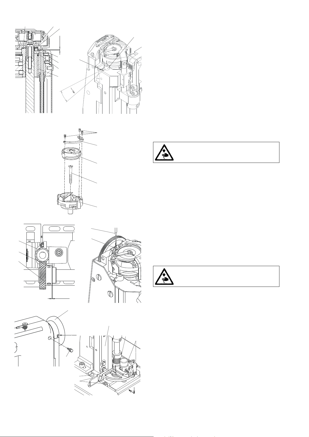
3.9.2 Setting the disengaging moment
Caution! Danger of injury!
Switch off the main switch! Before starting the
setting operation, wait until the motor stops!
The moment of 8 to 9 Nm is correctly set, when the screwed in
adjusting screws (3) come to lie 0.5 to 1.5 mm under the face
of the hub (2). When the clutch disengages during a normal
run, the screws are to be turned by one thread to the right and
a test is to be done during the running. In an opposite case,
when the hook is blocked, but the clutch does not disengage,
the disengaging moment of the clutch is to be reduced in
turning the screws to the left.
Caution!
The clutch guarantees only one mutual position
of the hub of the lower shaft (2) and that of the
belt wheel (1). No checking according to the gauge
marks is needed. Putting the clutch out of operation by
excessive tightening of the screws (3) can cause, when
blocking the hook, the destruction of the gear within the
drive of the hook.
3.10 Indented belt transmission
3.10.1 Setting the tensioning roller of the
indented belt
The optimum tension of the indented belt (1) is attained in
4
3
2
1
setting the tensioning roller (2) in such position, when the
roller applies the pressure of F = 20 N against the belt. The
roller must be side set in such a way that the edge of the
indented belt does not overlap over the edge of the roller.
Caution! Danger of injury!
Switch off the main switch! Before starting the
setting operation, wait until the motor stops!
- Remove the handwheel and the belt guard, remove the V-
belt.
- Unlock the fastening of the loop, on which the roller (2)
is mounted in such a way that the loop turns freely.
- Lift the roller (2) upwards and, thereafter, using the dynamo-
meter (4), pull horizontally the roller in applying the force of
2O N. In this position, tighten the fastening screw (3).
- Check the side shifting of the roller.
21

432
3.10.2 Replacing the indented belt
To observe: in machines with Mini-stop first remove the driving
toothed belt as instructed in par. 3.12.
When replacing the indented belt, the mutual position of the
pulleys (4 and 5) should be maintained.
Caution! Danger of injury!
Switch off the main switch! Before starting the
setting operation, wait until the motor stops!
- Remove the handwheel, the belt guard and the V-belt.
- Remove the retaining ring (1) and remove the backtacking
lever (2).
- Mark with a pencil the instantaneous position of the
indented pulleys against the machine head in any position.
51
- Remove the indented belt (3) from the bottom indented
pulley (4) first, and then remove the whole belt.
- Apply a new indented belt on the top indented pulley (5)
first.
- Turn both indented pulleys in the formerly marked positions
and apply the indented belt on the indented pulley (4).
- Tension the belt and mount the dismantled components in
the inverse order.
3.11 V-belt, motor - head
3.11.1 Tensioning
3 21
10 N
4
l - 20mm
10 N
Caution! Danger of injury!
Switch off the main switch! Before starting the
setting operation, wait until the motor stops!
The belt is correctly tensioned, when the opposite sides of
the belt approach one to another by up to 20 mm in applying
the force of 10 N. The belt is tensioned in turning respectively
the motor in its holder.
3.11.2 Replacing the V-Belt
Caution! Danger of injury!
Switch off the main switch! before starting the
setting operation, wait until the motor stops!
- Loosen the screw (1) of the positioner arrest (2) and tilt the
arrest.
- Unscrew the screws (3) of the handwheel.
- Unscrew the screws (4) of the belt guard and tilt the guard.
- Remove the belt guard of the motor and tilt the protections
against falling out the belt from the motor pulley.
- Replace the belt.
- Tension the belt (see par. 3.11.1).
3.12 Driving toothed belt
3.12.1 To exchange the driving toothed belt
Caution! Danger of injury!
Switch off the main switch! before starting the
setting operation, wait until the motor stops!
- Remove the machine head from the stand (uncouple the
motor cables, the machine head cable and screw off the
wood screw and the screw from the hinges).
- Remove the belt guard.
- Replace the belt.
22

5
6
1
7
8
3.13 Lubrication
3.13.1 Description
In the main lubrication reservoir (1) there is a suction wick (2)
which wipes against the shaft (3). The wick (4) collects oil
from the shaft (3) and feeds it into the wick (5) which
distributes oil to the lubricated spots. The left branch lubricates
the needle and the thread mechanisms. The right branch
lubricates the mechanism of the stitch length and, thereafter,
pushed into the box (11). The wick (6) sucks off the excessive
oil from the needle and the thread mechanisms and also
pushed into the box (11). The lubrication reservoir (7) feeds
oil through the wick (8) for lubricating the hook. The wick (9)
lubricates the shifting wedge of the feed clutch. The wick (10)
lubricates the gear of the hook drive.
10 11
9
543 2
1
3.13.2 Refilling oil
For lubricating the machine oil Esso SP-NK 10 is used or
other oil with the same quality. When putting the machine
into operation, each mechanism of the machine is to be
lubricated with several drops of oil. Oil is only refilled thereafter
into the oil reservoirs using an oil can into the holes in the oil
1
2
level indicators. The oil reservoir (1) is to be filled up to the
half of its content. The oil reservoir (2) is filled up to the
pouring holes.
3.13.3 Multiple oil use
Oil which runs into the oil cup is collected in the collector (1)
2
1
1
23
and may be reused for refilling the oil reservoirs in the machine
- see par. 3.13.2.
The oil collector (1) with the collected oil is uscrewed and the
top part of the oil can (2) which is added in the machine
packing is screwed in. Oil is then refilled into the reservoirs on
the machine head and everything is put into the original
condition.

3
2
1
4. Thread trimming
4.1 Description of the trimming mechanism
A
13
4
12
B
C
During the trimming cycle, the moving trimming knife (1), in
an opportune moment, hooks up the sewing threads and pulls
them in the sense of the arrow (A) against the fixed knife (2)
until the threads are trimmed. The spring (3) holds the hook
thread after being trimmed off. The moving knife (1) is mounted
on the shaft (4) which turns by means of the lever (5) under
the effect of the fork (6) fixed on the shaft (7) which is shifted
by the electromagnet (8) from its starting position in the sense
of the arrow (B). When moving back in the sense of the arrow
(C), the shaft (7) is shifted by the cam (9) through the pickup
roller (10) into the starting position. The spring (11) maintains
the mechanism in its starting position. The electromagnet
(12), in an opportune moment, loosens the main tensioner
(13). At the end of the trimming cycle, both electromagnets (8
and 12) are switched off.
65
11 10
97
8
4.2 Setting the pickup roller
1
4
2
5
3
A
6
The holder of the pickup roller (1) is to be fixed in such a way
that it is positioned, in its starting position, between the shaft
(2) and the shaft (3), the respective gap A = 0.2 to O.4 mm.
Caution! Danger of injury!
Switch off the main switch! Before starting the
setting operation, wait until the motor stops!
- With the loosened screw (4), put the holder of the pickup
roller (1) up to the stop against the bracket (5) and, at the
same time, the shaft (2) up to the stop against the shaft
(3).
- With the holder (1) held on the stop, shift the shaft (2) in
such a way that there appears the gap A = 0.2 to 0.4 mm,
and tighten the screw (4).
- Check the gap A in shifting the armature (6).
4.3 Setting the cam
The position of the cam (1) against the shaft (2) is to be such,
so that when the adjusting pin is in contact with the shaft (4),
the protractor scale of the handwheel (6) shows just the angle
of 108°. If the pickup roller (5) is in its starting position of
rest, the clerarance between the roller (5) and the cam (1)
should be as small as possible but sufficient to prevent the
cam from getting into accidental contact with the roller.
513824
108
Caution! Danger of injury!
Switch off the main switch! Before starting the
setting operation, wait until the motor stops!
- Set the angle of 108° on the handwheel (6) and lock it with
the screw (7) which is included in the accessory of the
machine (tighten with care).
- Shift the pickup roller (5) in the sense of the arrow up to the
6
o
7
stop.
- Insert the adjusting pin (3), which is included in the
accessory, into the cam and turn the cam, until the pin (3)
gets the contact with the shaft (4).
- Insert a gauge having the thickness of 0.1 mm between the
cam (1) and the pickup roller (2) and shift the cam against
the gauge up to the stop. Tighten then the screw (8).
- Loosen the blocking of the handwheel, turn a bit the cam
and tighten the second fastening screw of the cam too.
24

4
1
2
563
4.4 Setting the fork
In the starting position of rest of the trimming mechanism,
when the holder (1) is in contact with the bracket (2), the axis
of the fork (3) must intersect the axis of the shaft (4).
Caution! Danger of injury!
Switch off the main switch! Before starting the
setting operation, wait until the motor stops!
- Shift the shaft (5), until the holder (1) strikes the bracket (2).
- Loosen the screw (6).
- Shift the fork (3) in such a way that its axis intersects the
axis of the shaft (4).
- Tighten the screw (6).
A
3
4
5
4.5 Setting the moving knife
The moving trimming knife (1) is to be placed in its starting
position at rest with its end at the distance of the measure
A= 0.1 to 0.5 mm from the edge of the fixed trimming knife
(2).
The height setting is to be such that its top surface is 1.8 mm
below the top surface of the throat plate.
Caution! Danger of injury!
Switch off the main switch! Before starting the
setting operation, wait until the motor stops!
- Loosen the screws (4 and 5).
4
- Turn the moving trimming knife (1) in the sense of the arrow
and set it in height. Tighten the screw (5).
- Turn the moving trimming knife (1) into its starting position
in such a way that the measureA = 0.1 to 0.5 mm is
attained. Tighten the screw (4).
4.6 Setting the height of the fixed knife and of the
retaining spring of the lower thread
The fixed knife (1) and the retaining spring (2) are fixed on
the holder (3). This holder is fixed with the screw (4) on the
2
1,8 mmm
1
post of the hook (5). In its height, the holder (3) is to be set in
such a way, so that the top surface of the fixed knife (1) is by
1.8 mm below the top surface of the throat plate.
1/2
1/2
45
3
321
4
300
25
Caution! Danger of injury!
Switch off the main switch! Before starting the
setting operation, wait until the motor stops!
- Loosen the screw (4).
- In shifting the holder (3) in the hook post (5), set necessary
position of 1.8 mm.
- Tighten up the screw (4), check the correct setting.
4.7 Setting the fixed knife
The fixed trimming knife (1) is to be tensed up using the
screw (2) in such a way, so that it bears against the moving
trimming knife in the 1/2 of its length. The knives need not to
trim untensioned threads.
Caution! Danger of injury!
Switch off the main switch. Before starting the
setting operation, wait until the motor stops!
- Set the angle of 300° on the handwheel (4).
- Shift by hand the moving knife (3) into the marked position.
- Loosen the screw (2)ba hand, in shifting the fixed knife (1)
o
set its position, tighten then the screws (2).
- Check the bearing spot of the moving trimming knife (3) on
the fixed trimming knife (1) and give it a correction, if needed.

31
4
1
213
3
4.8 Setting the retaining spring of the hook thread
The retaining spring (1) holds the hook thread after having
performed the trimming. It is to be set in such a way that the
force necessary for pulling out the thread from the retaining
spring (1) is approximately equal to the force necessary for
pulling out the thread from the hook.
Caution! Danger of injury!
Switch off the main switch! Before starting the
2
- Shape the retaining spring (1) in such a way that it fits close
with all its surface (without wedge) onto the moving trim-
ming knife (3).
- Shape the retaining spring in such a way that it fits close,
with the slightly tightened screw (2), onto the moving
trimming knife without any pressure.
- Tighten the screw (2), until the necessary force for pulling
the thread from the retaining spring is attained. The pulling
force is tested using a screwdriver (4) according to the
illustration.
The adjusting screw (2) should not be screwed in in such
a way that the retaining spring gets over the perimeter of
the moving trimming knife.
setting operation, wait until the motor stops!
Caution!
The setting of the retaining spring (1) depends
on the setting of the hook tension and differs
then according to the respective sewing category.
4
5
6
132
4.9 Setting the switching of electromagnets
The electromagnets of the trimming device and loosening of
the tensioner must work in accordance with the diagram. This
is ensured by setting the stopmotor (see the instructions for
use of the stopmotor).
1- 1. position of the needle (225° on the handwheel)
/135° Mini-stop EFKA DC 1550/DA320/
2- 2. position of the needle (64° on the handwheel)
3- position of stopping the tensioner (10° ÷ 25° on the hand-
wheel)
4- movement of the pickup roller
5- current of the trimming device electromagnet
6- current of the tensioner loosening electromagnet
26

1
7
48
63
5
2
5. Material edge trimming
5.1 Description of the trimming mechanism
The trimming mechanism is a component part of the hook
post. The movement of the trimming knife (1) is adjustable
within the extent of 1,2 4,3 mm. It is derived from the proper
(motor) drive (2), from the compensating clutch (3) by means
of the eccentric (4) and the eccentric shaft, the connecting
rod (5) and the leverage (6) with the possibility of an im-
mediate switching-off using the push button (7). This
movement is then transmitted by the vertical shaft onto the
holder of the trimming knife (8).
134
2
5
231
5.2 Dismantling and assembly of the motor
- trimming drive
The complete trimming drive is fastened on the bedplate of
the machine using three screws (1).
Caution! Danger of injury!
Switch off the main switch! Before starting the
setting operation, wait until the motor stops!
Dismantling
- Unscrew the screw (2).
- Loosen the screws of the adjusting ring and of the feeding
clutch (not illustrated), then the screws of the chain trans-
mission (3) and shift out the feeding shaft (4) in the arrow
direction up to the necessary distance.
- Disconnect the connector of the supply cable (5).
- Remove the trimming drive.
When remounting, proceed in a reverse sequence.
5.3 Setting of the trimming knife lifting
The standard size of the trimming knife lift is set up to about
2,5 mm which suits the majority of the sewing operations. For
trimming difficult materials, this lift is to be increased to the
maximum of 4.3 mm. When sewing and trimming small inner
curves, the lift is to be lowered to the minimum of 1.2 mm.
Caution! Danger of injury!
Switch off the main switch! Before starting the
setting operation, wait until the motor stops!
1 2
- Loosen the screws (1) and set the white point on the eccentric
flange against the white adjustment mark of the drive holder
(2).
- Hold the eccentric (1) in its set up position and, in turning
the ring (3) fastened on the eccentric shaft, set the necessary
knife lift /to get the standard lift of 2.5 mm, set the ring (3) at
the half angle between the adjustment marks MIN. and MAX./
- Tighten the screws of the eccentric (1).
5.4 Replacement and setting of the trimming knife
position
5.4.1 Replacement of the knife and setting
of the distance between the knife and
the throat plate insert
The distance between the knife and the throat plate insert is
to be about 0,05 mm. the knife should not touch the insert
when moving it gets heated and blunt.
Caution! Danger of injury!
Switch off the main switch! Before starting the
setting operation, wait until the motor stops!
- Loosen the nut (1).
- Lift the holder (2) and remove the knife in the arrow direction.
- Mount the new knife, set the necessary distance and tighten
the nut (1).
27

5.4.2 Setting of the knife position (turning) in
the sewing direction
B
A
B
A
1
4
2
3
When sewing models with big curves, the knife is to be set in
such a way, so that the trimming corner (B) in its front dead
centre is at the level of the needle when it enters into the
throat plate (standard setting).
When sewing models with corners and narrow inner curves,
the trimming knife is to be set behind the needle in such a
way, so that in the moment when the needle leaves the throat
plate and the trimming corner of the knife (B) is in its front
dead centre, there is a distance A between the needle and
the cutting corner of the knife , that is the width of the trimmed
edge.
Caution! Danger of injury!
Switch off the main switch! Before starting the
setting operation, wait until the motor stops!
Standard setting
- Turn the shaft of the trimming drive using the ring (1), until
the trimming corner of the knife (B) gets the front dead centre.
- Turn the hand wheel until the needle enters the throat plate.
- Loosen the screws (2) and (3) and adjust the knife with the
holder (4) and the sleeve (5) as required.
- Tighten the screws (2) and (3).
Setting for models with inner curves
- Turn the shaft of the trimming drive by means of the ring (1)
until the trimming corner of the knife (B) gets into the front
dead centre.
- Turn the hand wheel until the needle leaves the throat plate.
- Loosen the screws (2) and (3) and set the knife with the
holder (4) an the sleeve (5) as required.
- Tighten the screws (2) and (3).
5
1
3
2
Caution:
With any change of the knife position in the sewing direction,
we recommend to recheck the distance between the knife and
the throat plate insert, to correct eventually the distance in
accordance with 5.4.1.
5.4.3 Height setting of the knife
The bottom side (surface) of the knife (1) is to be set above
the sewn material in such a way, so that it enables a tight
passing above the material.
Caution! Danger of injury!
Switch off the main switch! Before starting the
setting operation, wait until the motor stops!
- Loosen the screw (2).
- In turning the eccentric (3) set the height of the knife as
required.
- Tighten the screw (2).
28

6
9 10 11
2
8
3
5.5 Setting of engaging and disengaging of
the trimming mechanism, of the engaging
and carried lever stop
5.5.1 Description
The material trimming mechanism is formed by a moving part
- lever (1) on the shaft, which is connected by means of the
lever (2) and the connecting rod (3) with the trimming
mechanism drive, and by a carried part - lever (4), the
5
12
7
4
1
component part of which is also the knife holder (6) by means
of the shaft (5).
The levers (1) and (4) are set up by means of mutually clamping
joints in such a way, so that the carried lever (4), when being
turned by 90°, fits into the moving lever (1) by means of the
pawl (7).
When the trimming mechanism is engaged, the carrying part
is connected with the carried pawl (7) which controls at the
same time the mechanism of the trimming drive (8).
The trimming mechanism, which is situated on the vertical
divided shaft (5) is put into its working position by the hand
lever (9) in turning it to the right. After having engaged the
trimming mechanism, the hand lever returns into its starting
position up to the stop (10) by means of the torsion spring
(11).
The trimming mechanism is disengaged by depressing the
push button (12) which loosens the pawl (7) from the slot in
the lever (1).
At the same time, the operating device of the microswitch is
being shifted and stops the running of the driving motor.
5.5.2 Setting of the engaging lever stop
1
2
3
The stop screw (1) is to be screwed in and locked by the nut
(2)in such a way, so that the engaging lever (3) is in its starting
position perpendicularly to the longitudinal axis of the
machine.
5.5.3 Setting of the position (shifting)
3
2
When the carrying lever (1) is in the half of the lift of its reversing
motion, the pawl (2) is to be situated symmetrically to the axis
of the switching off push button (3).
1
of the carrying lever
5.5.4 Setting of the carried lever stop
The stop screw (1) is to be screwed in and locked with the nut
(2) in such a way, so that, when being the trimming mechanism
disengaged, there is a clearance of 1 mm between the engaging
4
lever pin (3) and the pawl (4).
2
1
3
29

6
A
5
5.5.5 Setting of the trimming mechanism
engagement
When engaging the trimming mechanism still before fitting
the pawl (1) into the slot in the lever (2) there is to be the
clearance A = 0,01 up to 0,05 mm and the clearance B =
0,5 up to 0,6 mm.
1
Caution! Danger of injury!
4
3
2
Switch off the main switch! Before starting the
setting operation, wait until the motor stops!
B
9
8
2
1
- Loosen 2 screws (3) and 2 screws (4).
- In shifting vertically the microswitch (5), shift the cam (6)
until obtaining the clearance B and tighten then the screws
(4).
- Shift the lever together with the pawl (1) under the push
button (7) in such a way, so that the pawl does not still fits
into the slot.
- Set vertically the push button (7) on the clearance A and
tighten the screws (3).
- Loosen the screws (8) and, in shifting horizontally the holder
(9), set the microswitch (5) in such a way, so that the motor
of the trimming mechanism is switched off in the bottom
position of the push button (7) and switched on in its top
position.
5.5.6 Setting of the torsional moment
of the return spring
The return spring (3) should have the least moment, but ¨this
moment should be sufficient for returning the trimming knife
in its starting position after having switched off the trimming.
This means the spring should individually be set up in
accordance with the thickness and the stiffness of the trimmed
material.
4
Caution! Danger of injury!
Switch off the main switch! Before starting the
setting operation, wait until the motor stops!
- Loosen 2 screws (1) on the adjusting ring (2).
- In turning the ring (2) set at random the twisting moment of
3
the spring (3) and tighten both screws (1).
- Start sewing together with the edge trimming. Stop the
machine in the middle of the seam without removing the
sewn material. Using the push button (4), stop the trimming
function and follow up, if the spring (3) fulfils its required
function. Correct eventually the setting.
5.6 Sharpening of the knives
For various types of trimmed material, the Company MAIER
manufactures knives with respective profiles in various
qualities of materials and dimensions.
(The usable knives are given in the Directions for Use together
with the respective supply numbers of the Maier and Minerva
companies).
To obtain due quality of trimming, the knife should be ground
in wet condition on special grinding machines at short inter-
vals (of about 2 to 5 hours) corresponding to the durability of
the knife trimmer edge. The special grinding machines are
produced by the following companies:
FORTUNA WIEN GmBH, A-1151 WIEN-Pelzgasse 13,
Postfach 91
MAIER UNITAS GmBH NÜRTINGER Strasse 19, D-7316,
KÖNGEN, Postfach 1130
30

5.7 Sewing without trimming
4
3
1
2
The technological utilization of this machine with vibrating
bottom horizontal trimming is not limited only for sewing
operations with simultaneous edge trimming. It can be also
used for current operations in the shoemaking and fancy goods
indusries in accordance with the selected sewing categories
(accessories).
6
Caution! Danger of injury!
Switch off the main switch! Before starting the
setting operation, wait until the motor stops!
5
The dismantling operation is to be done in the position
trimming mechanism out of function.
- Remove the knife guard (1) and screw in anew its attachment
screw.
- Loosen the screw (2) and remove the complete holder (3)
together with the trimming knife (4) from the shaft (5). The
sleeve (6) is to remain on the shaft it serves for orienting
the position of the knife holder when remounting.
Caution :
Be sure in placing the dismantled component parts into the
drawer with regard to the protection of the trimming knife
cutting edge and to the possibility of injury.
6. Lifting the top roller by electromagnet
6.1 Description
The core of the electromagnet, respectively its pin must be set
in such a way that the presser foot lifting is enabled.
6.2 Setting the electromagnet pin
241
- Unscrew the cap of the core (1) of the electromagnet.
- Shift the core (2) with the bar (3) and loosen the locking
screw (4).
3
- By screwing the pin (3) in the core (4), set their mutual
position in such a way that the core is fully pushed in with
the maximum presser foot lift.
- Tighten the locking screw (4).
- Screw on the cap (1).
Caution! Danger of injury!
Switch off the main switch! Before starting the
setting operation, wait until the motor stops!
6.3 Setting the electromagnet current
The time response of the current of electromag. has 2 phases:
- initial switching on (0,2 ÷ 0,5 s) - the maximum force
- maintaining (when keying)
It is necessary to set max. 40 % of keying (see
instructions for use of the stopmotor). With a
higher value thereof and with a long period of the
presser foot in its lifted position there is a danger
of electromagnet overheating.
31

6.4 Aseembly of the top roller lifting
2
4
3
1
electromagnet
Caution! Danger of injury!
Switch off the main switch! Before starting the
setting operation, wait until the motor stops!
- Remove the rear guard (3).
- Using the screws (1), fasten the electromagnet (2) on the
rear guard (3) with the given orientation of the outlet cable
(4).
- Mount the rear guard (3).
- Connect the outlet cable (see par. 8).
- Set the pin of the electromaghet (see par. 6.2).
- Set the current of the electromagnet (see par. 6.3).
7. Backtacking using electromagnet
7.1 Description
The position of the electromagnet with regard to the
backtacking lever must be set in such a way that it enables the
maximum stitch length when sewing in forward and in rearward
sense. If this position is not correct, the length of the stitch
will be shortened in one or the other feed direction.
7.2 Electromagnet height setting
Caution! Danger of injury!
1
3
2
- Set the maximum stitch length.
- Set the position of the electromagnet (2) against the
5
4
midpoint of the grooves (1) of the guard (3).
- Mount the guard (3) on the head (the bar (5) must have a
clearance between the stop on the backtacking lever and
the extreme top position at least of 0,5 mm).
- The backtacking lever (4) is to be shifted into its bottom
position (the bar (5) is to be in contact with the backtacking
lever (4) ).
Switch off the main switch! Before starting the
setting operation, wait until the motor stops!
7.3 Setting the position of push-buttons
Caution! Danger of injury!
1
2
- By loosening the screws (1), it is possible to set the height
of the push-button holder.
Switch off the main switch! Before starting the
setting operation, wait until the motor stops!
7.4 Change of the function of push-buttons
The Function of the push-buttons can be changed in
accordance with the possibilities given by the stopmotor (see
instruction for use of stopmotor).
32

4
5
213
9
8
4
5
67
10
8. Connecting the electric elements on the
machine head
The connection of the electric elements (electromagnets,
backtacking, presser foot lifting, thread trimming, loosening
of the tensioner and push-buttons) is made by means of a
switchboard (1) fixed with its supporting plate (2) on the rear
8
9
side of the head by means of two distance screws (3) (In the
Fig., these electric elements are disconnected).
Connecting spots :
4 - backtacking electromagnet
5 - trimming electromagnet
6 - tensioner loosening electromagnet
7 - presser foot lifting electromagnet
8 - connector of push-button connecting
9 - connector of coupling the head with the stopmotor
10 - connecting cable of the head and stopmotor
Wiring diagram of connecting the electric elements of the
machine head.
6
7
9. Drive, control panel, position sensor
The detailed information concerning the drive, the control
panel and the setting of the position sensor is given in the
manual of the drive and of the control panel.
10. Lighting
1
2
5
10.1 Mounting on the machine head
Caution! Danger of injury!
Switch off the main switch! Before starting the
setting operation, wait until the motor stops!
- Mount the lamp on the machine head using the screws (3).
- The lighting (5) conductor is to be led through the guard (1)
into the channel of the head on its rear side.
10.2 Lamp replacement
Caution! Danger of injury!
3
- Remove the guard (1) by unscrewing the screw (2).
- Remove the lamp from the machine head by unscrewing
4
two screws (3).
- Shift the glass (4).
- Loosen two screws of the lamp holder.
- Replace the lamp.
Switch off the main switch! Before starting the
setting operation, wait until the motor stops!
Use only 12 V, 10 W lamps. With higher values of
the lamp power, there is a danger of overheating.
33

11. Maintenance
Caution! Danger of injury!
The maintenance operations should be performed only with the machine switched off and with the motor stopped!
In the following table there are given the operations which should be performed and the respective time intervals between the
individual operations.
Operation Time interval
Removal of the throat plate and its cleaning out.Cleaning out of the wheel feeder, hook and their
surrounding space. Removal of the residues of material and threads from the top roller. 1 day
Checking the oil level in oil reservoirs. 1 month
Checking the hook wear. Checking the function of the safety clutch against the hook overload. 6 months
Checking the V-belt and the indented belts, checking the friction wheels of the drive convertion unit. 1 year
12. Setting the machine according to the sewing category
12.1 Introduction
The sewing machine enables sewing within the extent from the light to medium heavy-duty sewing. The setting of the machine
must be adapted to the sewing parameters including also replacement of some components, such as e.g. needle, the throat plate
insert, the spring of the main tensioner, the top roller. For this reason, the setting of the machine is divided into 3 categories:
1 ... light sewing
2 ... medium sewing
3 ... medium heavy-duty sewing
In the factory, where this machine has been manufactured, the machine has been set with respect to the standard parameters of
the required sewing category which is designed by the number included in the commercial designation of the machine. If the user
desires changing the given setting to another sewing category, this operation should be performed by a specialized mechanician.
Caution!
When changing the sewing category, loosen the tensing up of the fixed trimming knife.
Otherwise there is a danger of destruction of the moving knife.
The standard parameters of sewing are described in the following paragraph. The actual parameters of sewing inside the given
sewing category may be different, which means that the machine operative must adapt respectively the setting of the machine,
e.g. the tension of the upper thread.
34

12.2 Table of setting the machine according to the sewing category
Commercial designation of the machine 4181 - 1XX - X
Sewing
cate-
gory
-100
-200
-300
Setting as per Instructions for service 3.5.4.1.2 3.3.2 3.5.4.2.3 3.6.8.1 3.6.8.2 3.4.5
chapter
Standard sewing parameters
Thickness Number Stitch Label Distance
of one of length number between
material material o f the
layer layers thread needle
2)
mm mm
PES axis and
the work
0,8 2 2 70 0,8
1 2 2,5 40 1,2
1,5 2 3 20 1,5
Instructions manual 3.2 6.5 6.4 6.4
Instructions for assembling
Needle Sewing Position Width Feeder Presser Presser Thread tension Thread Spring
size speed of feeding of needle - top roller top roller
6) 7) 5) 4)
0,01 mm st/min. mm mm mm mm N N
lever pin plate pitch diameter position tensioner
2.4
4.5
Standard machine setting 1)
3)
insert of teeth needle hook
hole thread thread
limiter of main
522 099 004 800 80
22 080
262 083
1) The standard setting of the machine for the category 3 concerns a decorative stitching, when it is difficult to match a good
stitch interlocking with a faultless function of the thread trimming device. Otherwise, when sewing material of considerable
overall thickness, it will be necessary to increase the overtopping of the teeth above the needle plate and to increase also the
needle thread tension.
2) The thickness of a layer is measured using an engineer slide calliper with the pressure of jaws of about 10 N.
3) The values of tension are only orientative ones and it is necessary to adapt especially the tension of the shuttle thread
according to the stiffness of the material. An excessive tension of the threads when sewing soft materials causes material
wrinkling.
4) One of the two springs ist mounted, the other one is enclosed in the machine accessories.
5) When changing markedly the sewing category together with changing the tension of the shuttle thread, it is necessary to
modify the tension of the retaining spring of the trimming device according to the paragraph 4.7.
6) When changing markedly the sewing category together with a marked change of the needle number, it is necessary to correct
the setting of the distance of the shuttle from the needle, according to the paragraph 3.1.3.
7) There are in use various types of feeders with the purpose of avoiding imprinting the teeth in the lining leather. Otherwise, it
is possible to use any feeder.
35
 Loading...