

Page 1
Umbauanleitung für Handverriegelung
Teilesatz 0367 595084
Teile-Nr./ Part-No.:
Instructions for converting for manual backtacking
Kit 0367 595084
0791 367770
1. Verwendung des Teilesatzes
Folgende Unterklassen der Kl. 367 können mit dem Teilesatz “Handverriegelung” nachgerüstet
werden: -170115, -170315, -180115, -180315.
2. Lieferumfang
Bevor Sie mit dem Umbau beginnen: Bitte überprüfen Sie, ob alle Bauteile des Nachrüstsatzes in dem
Lieferumfang enthalten sind.
Der Teilesatz besteht aus folgenden Bauteilen:
– 1 x Riemenabdeckung 0667 100040
– 1 x Zugfeder 0667 165220
– 1 x Hebel 0367 165960
– 2 x Linsenschrauben 9204 201667
– 1 x Kloben 0367 166003
– 1 x Passkerbstift 0578 000868
– 1 x Zyl. Kerbstift 0994 271360
– 1 x Schlauch 0367 165980
– 1 x Welle 0367 166020
– 1 x Bohrschablone 0367 165990
– 1 x Handgriff 0667 165570
3. Umbau der Maschine
Vorsicht Verletzungsgefahr !
Schalten Sie den Hauptschalter aus und ziehen Sie den Netzstecker,
bevor sie mit dem Einbau des Teilesatzes Handverriegelung beginnen.
Der Einbau darf nur von qualifizierten Technikern durchgeführt werden.
10
81 7
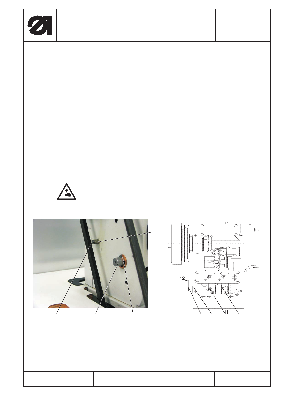
– Positionsgeber und Handrad entfernen.
–
Riemenschutz entfernen.
–
Ventildeckel entfernen.
–
Prüfen ob die Welle 0367 166020 durch die mitgelieferte Welle ersetzt werden muß. Überstand der
Welle 1 muß ca. 12 mm betragen.
–
Druckschrauben am Kloben 12 und Hebel 11 (0667 16374 nur bei Kl. 367-170315, -180315) lösen.
Ausgabe/Edition:
01. 2006
Printed in Federal Republic of Germany
171112
Blatt: von
Sheet: 1 from 4
Page 2
Umbauanleitung für Handverriegelung
Teilesatz 0367 595084
Teile-Nr./ Part-No.:
Instructions for converting for manual backtacking
Kit 0367 595084
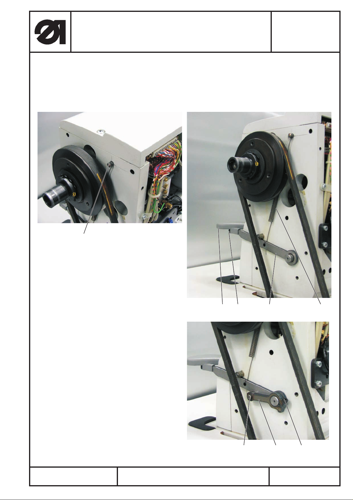
Zwei Sicherungsringe 7 auf der Welle 0367 166020 entfernen
–
Welle herausziehen
–
mitgelieferte Welle einbauen und Sicherungsringe aufstecken
–
– Druckschrauben des Hebels und des Rahmens festziehen
– Bohrung 6H13 nach Bohrschablone 0367 165990 bohren (mit handelsüblichen 6 mm Bohrer für
Stahl)
0791 367770
2
– Stift 2 (Teile-Nr. 0578 000868) einschlagen.
– Stift 8 (Teile-Nr. 0994 271360) in vorhandene
Bohrung einschlagen und mitgeliefertes
Schlauchstück 10 (Teile-Nr.) 0367 165980
über Stift ziehen.
– Hebel 3 (Teile-Nr. 0367 165960) auf Welle
stecken.
– Feder 4 (Teile-Nr. 0667 165220) einhängen.
– Klemmkloben 5 (Teile-Nr. 0367 166003)
auf Welle stecken
Bei max. Stichlänge muß der Stift 9 von
Klemmkloben 0367 166003 an
Hebel 0367 165960 anliegen
– Schraube 6 am Klemmkloben 5 anziehen.
– Handgriff 13 auf Hebel 3 mit Schrauben 14
(9204 201667) befestigen
– Stichlänge einstellen: siehe Serviceanleitung
Kapitel 2.3
– Einstellung der KFA (nur bei Kl. 0367-170315
und 0367-180315) vornehmen: siehe
Serviceanleitung Kapitel 2.9
– Ventildeckel, mitgelieferten Riemenschutz,
Handrad und Positionsgeber an die Maschine
bauen.
13 14 3 4
Ausgabe/Edition:
01. 2006
956
Printed in Federal Republic of Germany
Blatt: von
Sheet: 2 from 4
Page 3

Umbauanleitung für Handverriegelung
Teilesatz 0367 595084
Teile-Nr./ Part-No.:
Instructions for converting for manual backtacking
Kit 0367 595084
0791 367770
1. Use of the set of parts
The following subclasses of cl. 367 can be retrofitted with the set of parts ”manual backtacking”:
-170115, -170315, -180115, -180315.
2. Scope of delivery:
Before you start with the conversion: Please check whether all components of the retrofit kit are
included in the delivery.
The kit consists of the following components:
– 1 x belt cover 0667 100040
– 1 x tension spring 0667 165220
– 1 x lever 0367 165960
– 2 x oval head screws 9204 201667
– 1 x block 0367 166003
– 1 x half length taper grooved pin 0578 000868
– 1 x grooved cylindrical pin 0994 271360
– 1 x hose 0367 165980
– 1 x shaft 0367 166020
– 1 x drilling template 0367 165990
– 1 x handle 0667 165570
Caution: Risk of injury !
Switch the main switch off and unplug the mains plug before you start
mounting the kit for manual backtacking. The assembly must be done by
qualified technicians only.
3. Conversion of the machine
10
81 7
– Remove synchronizer and handwheel.
–
Remove belt protection.
–
Remove valve cover.
–
Check whether the shaft 0367 166020 has to be replaced by the included one. The protrusion of the
shaft 1 must amount to approx. 12 mm.
–
Loosen the pressure screws at block 12 and lever 11 (0667 16374 with cl. 367-170315, -180315
only).
Ausgabe/Edition:
01. 2006
Printed in Federal Republic of Germany
171112
Blatt: von
Sheet: 3 from 4
Page 4

Umbauanleitung für Handverriegelung
Teilesatz 0367 595084
Teile-Nr./ Part-No.:
Instructions for converting for manual backtacking
Kit 0367 595084
Remove two circlips 7 from the shaft 0367 166020.
–
Pull the shaft out.
–
Mount the included shaft and slip circlips on.
–
– Tighten the pressure screws of the lever and the frame.
– Make drillhole 6H13 according to drilling template 0367 165990 (with customary 6 mm s teel drill).
0791 367770
2
– Knock in pin 2 (part no. 0578 000868).
– Knock pin 8 (part no. 0994 271360) in the
drillhole already existing and put the included
piece of hose 10 (part no. 0367 165980)
on the pin.
– Put lever 3 (part no. 0367 165960) on shaft.
– Hang in spring 4 (part no. 0667 165220).
– Put c lamping block 5 (part no. 0367 166003)
on shaft
With the maximum stitch length the pin 9 of
the clamping block 0367 166003 must abut on
lever 0367 165960.
– Tighten screw 6 at the clamping block 5.
– Fasten handle 13 on lever 3 with screws 14
(9204 201667).
– Adjusting the stitch length: see s ervice
instructions chapter 2.3
– Adjusting the short tail trimmer
(only with cl. 0367-170315 and 0367-180315):
see service instructions chapter 2.9
– Mount valve cover, included belt protection,
handwheel and synchronizer
.
13 14 3 4
Ausgabe/Edition:
01. 2006
956
Printed in Federal Republic of Germany
Blatt: von
Sheet: 4 from 4
 Loading...