

Page 1

281
Spezialnähmaschine
Serviceanleitung
Service Instructions
Service Instructions
D
GB
CN
Manufacturer: Dürkopp Adler Manufacturing (Shanghai) Co., Ltd.
Conta c t: Dürkopp Adler AG, PO Box 17 03 51, D-33703 Bielefeld, Potsdamerstr. 190, D-33719 Bielefeld,
Manufacturer: Dürkopp Adler Manufacturing (Shanghai) Co., Ltd.
Conta c t: Dürkopp Adler AG, PO Box 17 03 51, D-33703 Bielefeld, Potsdamerstr. 190, D-33719 Bielefeld,
Ausgabe / Edition: Änderungsindex Teile-Nr./Part.-No.:
01/2009 Rev. index: 00.0 PrintedinChina 0791 281641
1201 Luoshan Road, Pudong New Area, Shanghai 200135, China
Phone +49 (0) 521 9 25 00, Fax +49 (0) 521 9 25 24 35, www.duerkopp-adler.com
1201 Luoshan Road, Pudong New Area, Shanghai 200135, China
Phone +49 (0) 521 9 25 00, Fax +49 (0) 521 9 25 24 35, www.duerkopp-adler.com
Page 2

Alle Rechte vorbehalten.
Eigentum der Dürkopp Adler und urheberrechtlich geschützt. Jede, auch auszugsweise Wiederverwendung
dieser Inhalte ist ohne vorheriges schriftliches Einverständnis der Dürkopp Adler verboten.
All rights reserved.
Property of Dürkopp Adler and copyrighted. Reproduction or publication of t he content in any manner, even in
extracts, without prior written permission of Dürkopp Adler, is prohibited.
All rights reserved.
Property of Dürkopp Adler and copyrighted. Reproduction or publication of t he content in any manner, even in
extracts, without prior written permission of Dürkopp Adler, is prohibited.
Copyright ©
Dürkopp Adler - 2009
Page 3

General safety instructions
The non-observance of the following safety instructions can cause
bodily injuries or damages to the machine.
1. The machine must only be commissioned in full knowledge of the
2. Before putting into service also read the safety rules and
3. The machine must be used only for the purpose intended. Use of
4. When gauge parts are exchanged (e.g. needle, presser foot, needle
5. Daily servicing work must be carried out only by appropriately
instruction book and operated by persons with appropriate training.
instructions of the motor supplier.
the machine without the safety devices is not permitted. Observe all
the relevant safety regulations.
plate, feed dog and bobbin) when threading, when the workplace is
left, and during service work, the machine must be disconnected
from the mains by switching off the master switch or disconnecting
the mains plug.
trained persons.
6. Repairs, conversion and special maintenance work must only be
carried out by technicians or persons with appropriate training.
7. For service or repair work on pneumatic systems, disconnect the
machine from the compressed air supply system (max. 7-10 bar).
Before disconnecting, reduce the pressure of the maintenance unit.
Exceptions to this are only adjustments and functions checks made
by appropriately trained technicians.
8. Work on the electrical equipment must be carried out only by
electricians or appropriately trained persons.
9. Work on parts and systems under electric current is not permitted,
except as specified in regulations DIN VDE 0105.
10. Conversion or changes to the machine must be authorized by us
and made only in adherence to all safety regulations.
11. For repairs, only replacement parts approved by us must be used.
12. Commissioning of the sewing head is prohibited until such time as
the entire sewing unit is found to comply with EC directives.
13. The line cord should be equipped with a country-specific mains
plug. This work must be carried out by appropriately trained
technicians (see paragraph 8).
It is absolutely necessary to respect the safety
instructions marked by these signs.
Danger of bodily injuries !
Please note also the general safety instructions.
Page 4

Page 5

Contents Page:
Part 3: Service Instructions Class 281
(Edition 01/2009)
1. General
1.1 Tools and Gauges .............................................. 3
1.2 Adjustingaids................................................. 4
2. Feeding and sewing equipment
2.1 Timingofthethrusteccentric ....................................... 5
2.2 Timingoftheliftingcam........................................... 6
2.3 Feeddogheightandinclination...................................... 7
2.4 Feeddogpositionwithinthethroatplate................................. 8
2.5 Stitch length limitation ............................................ 9
2.6 Stitch length symmetry ........................................... 10
3. Sewing foot height and sew ing foot lifting
3.1 Pressure-barheight............................................. 11
3.2 Mechanical sewing foot lifting ....................................... 12
3.2.1 Liftingmotionandliftedsewingfootheight ............................... 12
3.3 Electromagnetic sewing foot lifting .................................... 13
3.3.1 Sewing foot lifter solenoid position .................................... 13
3.3.2 Mounting the sewing foot lifting solenoid ................................. 14
3.3.3 Replacing the shock absorbing washer of the sewing foot lifter solenoid ............. 16
3.4 Sewingfootpressure ............................................ 18
4. Thread-guiding parts
4.1 Releasing the needle thread tension ................................... 19
4.2 Threadtake-upspring............................................ 20
4.3 Thread regulator ............................................... 21
5. Needle bar height .............................................. 22
6. Hook setting
6.1 Looping stroke and distance between the hook point and needle .................. 23
6.2 Bobbin case holder.............................................. 24
GB
7. Thread trimmer
7.1 Controlcamfortheknifemotion...................................... 25
7.1.1 Controlcamposition............................................. 25
7.1.2 Distancebetweentherollerandthreadtrimmercam ......................... 26
7.2 Hookedknife ................................................. 27
7.3 Settingthecuttingpressure ........................................ 28
Page 6

Contents Page:
8. Setting the bobbin w inder
8.1 Switching off the bobbin winder ...................................... 29
8.2 Winding form of the bobbin ......................................... 30
8.3 Windingtightness .............................................. 30
9. Filling up oil (gear box) .......................................... 31
10. Hook lubrication
10.1 Setting the oil quantity for the hook .................................... 33
11. Maintenance ................................................. 34
Page 7

1. General
The present service instruction describes the adjustment of the special
sewing machine 281.
ATTENTION!
The operations described in the service instructions must only be
executed by qualified staff or correspondingly instructed persons
respectively!
Caution: Risk of injury !
In case of repair, alteration or maintenance work turn off the main
switch and make sure to protect the machine from powering up
accidentally.
Carry out adjusting operations and functional tests of the running
machine only under observation of all safety measures and with
utmost caution.
The present service instruction describes the adjustment of the sewing
machine in an appropriate sequence. Please observe in this
connection that various setting positions are interdependent. Therefore
it is absolutely necessary to perform the adjustment following the
described order.
For all setting operations of parts involved in the stitch formation use a
new needle without any damage.
Machine covers having to be screwed off and on again for checking
and adjusting operations are not mentioned in the text.
GB
Please note:
The shaft of the special sewing machine 281 is provided with flat spots.
This facilitates the adjustment considerably.
In case of adjustments on flat spots the first screw in rotation direction
is put on such a flat spot.
3
Page 8

1.1 Tools and Gauges
Art Size Figure
Allen key
Screw driver
Flat tip 0.7 x 4,5
Flat tip 0.3 x 3
Flat tip 0.7 x 4.5
5
4
3
2.5
2
1.5
Cross tip B2 -H
Open-end wrench 10
Gauge Needle bar height
0281 801819 for needle diameter 1.62 mm
Gauge Needle bar height
0281 800300 for needle diameter 2.00 mm
Setting pin For locking the machine at position 1 - 6
9301 022608
0281 800290
4
Gauge Feed dog height / Needle bar height
Page 9

1.2 Adjusting aids
1
2
4
3
The sewing machine can be locked in six different setting positions
with the locking pin 1 and the arresting notches 2 on the arm shaft
crank 3.
The crank has six notches which are marked on the handwheel by the
figures 1, 2, 3, 4, 5 and 6. In conjunction with marking 4 the figures
indicate the position of the notches in which the machine can be locked
with locking pin 1.
The figures simplify the finding of the arresting notches. A precise
setting can only be ensured by arresting the machine at the provided
notches.
GB
The following items should be adjusted in the various positions:
Pos. Symb. Description
Loop stroke
Distance between the hook point and needle
Feed dog standstill when stitch-length regulator moves
feed dog height
nd
2
needle position (thread lever upper dead centre)
Reference position machine head / Control cam for thread trimmer
st
1
Needle position
Needle in lowest position
5
Page 10

2. Feeding and sewing equipment
2.1 Timing of the thrust eccentric
2
1
Caution: Risk of injury !
Turnthemainswitchoff!
Check and set the feed standstill only when the machine is switched
off.
ATTENTION!
The thrust eccentric in the gear box 3 is already optimally set
ex factory.
The setting should preferably not be modified.
Standard checking
With the sewing machine arrested at locking position “2", there should
be no feeding movement if the reverse feed lever 2 is actuated and the
greatest stitch length is selected.
Correction
–
Set the greatest stitch length at the setting wheel 1.
–
Loosen the screws 5 at the lower toothed belt wheel 4.
–
Turn the lower shaft accordingly.
–
Fasten the screws 5 at the lower toothed belt wheel 4.
3
ATTENTION!
Should the lower shaft be misaligned, the following
positions must also be re-adjusted again:
4
5
6
l Hook (see chapter 6.1)
l Thread trimmer cam (see chapter 7.11)
l Lifting cam (see chapter 2.2)
Page 11

2.2 Timing of the lifting cam
5
1
2
3
3
4
1
GB
4
Caution: Risk of injury !
Turnthemainswitchoff!
Check and set the lifting cam only when the machine is switched off.
Standard checking
With the sewing machine arrested at locking position “2", align the
notches 1 (of the lifting cam 2) and 4 (of the traction rod 5).
Correction timing of the lifting cam
–
Arrest the sewing machine at locking position “2".
–
Loosen both screws 3 of the lifting cam 2.
–
Turn the lifting cam 2.
The notches 1 and 4 muss be aligned.
–
Tighten both screws 3 of the lifting cam 2 again.
7
Page 12

2.3 Feed dog height and inclination
Fig. A
7
8
Fig. B
Standard checking
Fig. A
The emerging height of the feed dog over the throat plate, its angle of
climb or the parallelism to the throat plate can be set via eccentrics 7
and 8.
With the sewing machine arrested at locking position “2", the height of
the centre of the throat plate (at the needle hole) is set ex factory:
0.9 mm with fine toothed feed dog
·
1.1 mm with coarse toothed feed dog
·
Thereby the feed dog is slightly rising from front to rear.
Fig. B
With this setting, the feed dog is parallel to the throat plate when
emerging.
8
Page 13

10
7
8
9
6
11
Caution: Risk of injury !
Turnthemainswitchoff!
Check and set the feed dog height and inclination only with the sewing
machine switched off.
Correction feed dog height
–
Arrest the sewing machine at locking position “2".
–
Loosen screws 6 and 9.
–
Turn the eccentric bolts 7 and 8.
In its highest position, the feed dog should protrude
by 0.9 (1.1) mm from the throat plate in the region of the needle hole.
–
Adjust the height and the inclination via the eccentrics 7 and 8.
Keep in mind that the adjusting of both eccentrics are
interdependent from each other.
–
Fasten screws 6 and 9 again.
GB
2.4 Feed dog position within the throat plate
Rule
With the sewing machine arrested at locking position “2", the feed dog
should be symmetric.
The distance is s imilar at the front and the rear.
Correction
–
Arrest the sewing machine at locking position “2".
–
Loosen screw 11.
–
Adjust the symmetry.
–
Fasten the screws 11.
The lateral clearance b must still be kept.
9
Page 14

2.5 Stitch length limitation
5
423
1
Caution: Risk of injury!
Turn off the main switch!
Check and set the stitch length limitation only with the sewing machine
switched off.
Standard checking
The maximum stitch length for the sewing machine is 4.5 mm.
With sewing equipment designed for smaller stitch length, the stitch
length must also be limited accordingly, in order to avoid damaging the
sewing machine or the sewing equipment.
Limiting the maximum stitch length
–
Set the allowed maximum stitch length for the sewing equipment on
the setting wheel 1.
–
Loosen both screws 3 of the limiting block 2.
–
Turn the limiting block clockwise against the threaded pin 5.
–
Fasten both screws 3 again.
10
Page 15

2.6 Stitch length symmetry
2
3
4
1
5
Caution: Risk of injury!
Turn off the main switch! Check and set the stitch length symmetry
only with the sewing machine switched off.
GB
Standard checking
The forward and reverse stitch length (4.0 mm) are already set ex
factory.
A verification can be done by using a cardboard as a sewing material
and sewing 10 stitch length (11 stitching) forward and next to it 10
stitch length (11 stitching) reverse without thread with the slowest
speed.
The total length of the 10 stitches in both directions should be the
same.
It may be necessary to re-adjust the symmetry of the stitch length after
repairs.
Correction
–
Set the maximum stitch length on the setting wheel 1.
–
Loosen the screw 3 in the clamping block 4.
–
Turn the shaft 2 in the clamping block 4.
–
Fasten the screw 3.
–
Check the stitch length again and set it anew if necessary.
Please note:
Even a slight twisting of the shaft leads to an essential change of the
stitch length.
This task must be carried out meticulously.
Furthermore it is important to make sure that when latching (with the
greatest stitch length set), the latch solenoid 5 does not hit its inside or
outside end position in order to avoid knocking noises or to prevent
from wearing out.
11
Page 16

3. Sewing foot height and sewing foot lifting
The maximum sewing foot lifting stroke amounts to:
12 mm with machines with electromagnetic sewing foot lifting.
·
14 mm with machines with knee lever.
·
9 mm factory setting.
·
3.1 Pressure-bar height
1
2
3
Caution: Risk of injury!
Turn off the main switch!
Check and set the pressure-bar height only with the sewing machine
switched off.
Standard checking
When the sewing foot sole 4 rests on the throat plate, a gap of 0.5 mm
should be available between the block 2 and the traction bracket 1.
Correction
–
Remove the face cover.
–
Loosen the screw 3.
–
Press the sewing foot downward against the throat plate.
This setting should not take place against the emerging feed dog!
–
Shift the block 2 in a way that a gap of 0.5 mm is available between
the block 2 and the draw angle 1.
–
Align the sewing foot so that the needle can stitch in the middle of
the slit of the sewing foot and fasten the screw 3 again.
–
Fix the face cover again.
12
4
Page 17

3.2 Mechanical sewing foot lifting
3.2.1 Lifting motion and lifted sewing foot height
5
2
34
1
6
GB
Caution: Risk of injury!
Turn off the main switch! Check and set the knee lever only with the
sewing machine switched off.
Standard checking
With the sewing foot resting on the throat plate, before the lifting
movement begins a lost motion should be perceptible at the knee lever.
The sewing foot lifting should be s et so high in a way that the needle
point 5 in arrested position (locking position 3) must not come above
the slit of the sewing foot 6.
Correction lifter motion (low er position)
–
Loosen the nut 3.
–
Adjust the screw 4.
With the sewing foot resting on the throat plate, a lost motion
should be perceptible at the knee lever.
–
Fasten the nut 3 again.
Correction lifted sewing foot height
–
Arrest the sewing machine at locking position “3".
–
Loosen the nut 1.
–
Adjust the lifting height through stop screw 2.
–
Fasten the nut 1 again.
13
Page 18

3.3 Electromagnetic sewing foot lifting
3.3.1 Sewing foot lifter solenoid position
2
4
1
Caution: Risk of injury!
Turn off the main switch!
Check and set the sewing foot lifting only with the sewing machine
switched off.
Standard checking
When operated, the anchor 2 of the solenoid 1 must always reach its
internal final position, because its power consumption will be reduced
to 30% after a sewing foot lifting.
The sewing foot lifting should be s et so high in a way that the needle
point 5 in arrested position (locking position 3) must not come above
the slit of the sewing foot 6.
Correction
–
Loosen screw 3.
–
Introduce a screw driver through the hole 4 and put it in the bracket
of the sewing foot lifting solenoid.
–
Change the position of the solenoid by swivelling the screw driver
upwards or downwards:
® Swivel the screwdriver handle upwards = smaller s troke
® Swivel the screwdriver handle downwards = greater stroke
–
Fasten both screws 3 again.
3
14
5
6
Page 19

3.3.2 Mounting the sewing foot lifting solenoid
3
2
10
1
654
–
Unscrew the handwheel 3, covering 2 and cover 1.
–
Unclamp the spring 4.
–
Loosen the screws 6 and remove the mounting flange 5.
GB
7
11
6a
9
8
–
Screw the holder 10 to the solenoid 8 u sing the screws 9 provided.
–
Fit the push rod 7 to the solenoid.
–
Screw the mounting flange 11 that has been removed to the holder
10 using one of the screws 6.
10
15
Page 20

14 13 8 18 17 16 15
–
Tilt the machine head backwards.
–
Loosen screw 14.
–
Using the mounting aid 13, push the pre-assembled sewing foot
lifting solenoid upwards in a way that the push rod 15 gets engaged
in the upper guide bore hole.
–
Fasten the mounting aid 13 with the screw 14.
–
Unscrew the threaded pin 17.
–
Push all the cables to the left of the shaft 16 of the threaded pin 17
and fasten the threaded pin again.
–
Lead the cable of the sewing foot lifting solenoid to the rear side of
the machine through the drilled hole 18.
16
66a4
–
Tilt the sewing machine head to the front.
–
Screw the holder 10 to the housing using one of the screws 6.
–
Unscrew the screw 6a and screw it into the second mounting hole
of the holder.
–
Loosen the screw 14, remove the mounting aid and fasten the
screw 14 again.
–
Put in the spring 4.
Page 21

1-3
5
–
Connect the cable of the sewing foot lifting solenoid to the terminal
blocks, one wire to one of the terminal from 1 to 3 and the second
one to the terminal 5.
–
If necessary, set the sewing foot height anew (see chapter 3.3.1).
–
If necessary activate the sewing foot lifting solenoid (see operating
instructions for the control unit).
Please note!
The removal of the sewing foot lifting solenoid is the reverse of the
mounting procedure.
GB
3.3.3 Replacing the shock absorbing washer of the sewing foot lifter solenoid
Caution: Risk of injury!
Turn off the main switch!
Proceed to the removal of the sewing foot lifting solenoid with the
sewing machine switched off!
After years of intensive use, a dimensional change of the shock
absorbing washer 5 may occur.
6
5
4
3
1
2
This is noticeable by the slower lowering of the sewing foot or an
impact noise when the solenoid is operated.
It may signify that before the foot has reached the material to be sewn
completely it has already started to sew (risk of skipped stitches at the
seam beginning).
–
Remove the lifting solenoid 1.
–
Remove the lock washer 6.
–
Remove spring 4 and bush 5.
–
Remove the anchor 2 from its housing.
–
Replace the shock absorbing washer 3 (0271 001767).
–
Put on spring 4 and bush 5.
–
Fix the lock washer 6 again.
–
Mount the lifting solenoid again (see chapter 3.3.2).
17
Page 22

3.4 Sewing foot pressure
1
Standard checking
The figures on the setting wheel 1 gives the sewing foot pressure
in “N”.
(1kp = approx. 10N).
The required sewing foot pressure depends on the following
parameters:
Sewing speed
·
Damping characteristics of the material to be sewn
·
Number of plies (layers forming the material to be sewn)
·
The material that is to be sewn must not “swim”.
However, the sewing foot should not exert more pressure than
necessary, otherwise a strong shifting of the ply occurs (ruffling).
Correction
–
Set the sewing foot pressure by turning the handwheel 1.
Increase the pressure = Turn it clockwise.
Decrease the pressure = Turn it counter-clockwise.
18
Page 23

4. Thread-guiding parts
4.1 Releasing the needle thread tension
3
1
2
GB
Caution: Risk of injury!
Turn off the main switch!
Check and set the releasing of the needle thread tension only when
the machine is switched off.
Standard checking
Pressing on the axle 3 opens the thread tensioner by approx. 1 mm.
With the thread tensioner closed and with no thread between the
tension discs the axle 3 should have a clearance of approx. 0.3 mm.
Correction
–
Loosen the threaded pin 2.
–
Move the solenoid 1 axially.
Check the following: distance approx. 1.0 mm / clearance 0.3 mm.
–
Fasten the threaded pin 2 again.
19
Page 24

4.2 Thread take-up spring
2
6
5
1
4
4
3
2
Caution: Risk of injury!
Turn off the main switch!
Check and set the thread take-up spring only with the sewing
machine switched off.
Standard checking
The thread take-up spring 2 should keep the needle thread under
tension at least until the needle point has penetrated the material to be
sewn.
Correction spring tension
When removing the complete thread tension unit, please make
absolutely sure not to lose the release pin 6 and to include it again
when mounting the thread tension unit.
–
Loosen the threaded pin 4.
–
Unscrew the complete thread tension unit.
–
Loosen the threaded pin 3.
–
Adjust the tension strength by turning the tension bolt 1.
The tension of the thread take-up spring depends on the material
being sewn and the thread used. The value should be between 20
and 50 cN (1 cN = 1 g).
–
Fasten the threaded pin 3.
–
Insert again the complete thread tension unit including the release
pin 6.
Correction spring travel
–
Loosen the threaded pin 4.
–
Twist the bush 5.
The spring 1 must should keep the needle thread under tension at
least until the needle point has penetrated the material to be sewn.
Recommended spring travel: 6.5 mm.
–
Fasten the threaded pin 4 again.
20
Page 25

4.3 Thread regulator
1
2
3
Caution: Risk of injury!
Turn off the main switch!
Check and set the thread regulator only when the machine is switched
off.
GB
Standard checking
The setting of the thread regulator 2 depends on:
Material thickness
·
Thread size
·
Stitch length.
·
It has to be set that the thread is guided around the hook and kept
under control.
In the position “0” occurs the highest thread output as needed with
particularly large stitch lengths and thick sewing threads.
The thread regulator is set ex factory between position “2" “ and “3”
–
Insert a fabric.
–
Thread the needle and hook thread.
–
Tilt the machine head backwards.
–
Turn the handwheel slowly and check how tight the thread is
guided around the hook.
If the thread regulator is set correctly the thread looping will run
smoothly (without surplus), without jumping over the largest hook
diameter.
In the process the thread take-up spring moved at most 0.5 mm.
Correction
–
Loosen screw 1.
–
Shift the thread regulator 2.
Thread regulator to the left = more thread.
Thread regulator to the right = less thread.
–
Fasten screw 1.
21
Page 26

5. Needle bar height
1
4
2
3
Caution: Risk of injury!
Turn off the main switch!
Check and set the needle bar height only with the sewing machine
switched off.
ATTENTION RISK OF BREAKAGE!
It is not permitted to fix an adjusting block on the needle bar of
the class 281. Doing so may damage the surface of the needle bar.
Standard checking
There are two types of needle bar for the class 281:
Needle shank diameter 1.62 mm, needle system DB x1
·
Needle shank diameter 2.0 mm, needle system 134
·
Should a setting of the needle bar height occur without using the
gauge, use the following reference value: 0.8 mm distance between
the hook point (lower edge) and the needle eye (upper edge).
22
Correction
–
Remove the throat plate and the sewing foot.
–
Place the gauge 4 on the surface of the throat plate.
–
Fit the gauge 3 as far as it will go into the needle bar instead of a
needle and fix it by tightening the fastening screw.
Gauge 0281 801819 Needle bar height for
needle diameter 1.62 mm
Gauge 0281 800300 Needle bar height for
needle diameter 2.00 mm
–
Arrest the sewing machine at locking position “6".
–
Loosen the screw 1.
–
Push the needle bar 2 downwards.
The foot of the gauge 3 must rest on the gauge 4 without a gap.
–
Fasten the screw 1 again.
ATTENTION !
The screw retaining the needle must point to the right (seen from
the operator’s side).
–
Fix the throat plate and the sewing foot again.
Page 27

6. Hook setting
6.1 Looping stroke and distance between the hook point and needle
2
3
2
3
1
GB
Caution: Risk of injury!
Turn off the main switch!
Check and set the looping stroke and the distance between the hook
point and needle only with the sewing machine switched off.
Standard checking
The loop stroke is the distance covered by the needle bar from the
bottom dead center up to the point where the hook tip 2 coincides with
the middle of the needle
(line A-A).
The looping stroke amounts to 1.8 mm.
With the sewing machine arrested at locking position “1", the hook
point 2 should be at the center of the needle.
The lateral distance between the hook point 2 and the needle scarf 3
should amount between 0.05 to 0.1 mm.
1
Correction
–
Remove the sewing foot, the throat plate and the feed dog.
–
Insert a new needle.
–
Arrest the sewing machine at locking position “1".
–
Loosen the fastening screw 1 of the hook.
–
The distance between the hook point 2 and the needle scarf 2
should amount between 0.05 to 0.1 mm.
–
Fasten the fastening screw 1 of the hook again.
–
Fix the sewing foot, the throat plate and the feed dog again.
23
Page 28

6.2 Bobbin case support
23
1
2
4
3
Caution: Risk of injury!
Turn off the main switch!
Check and set the bobbin case support only with the sewing machine
switched off.
Standard checking
The bobbin case support is factory set.
After a replacement of the support, the new support may eventually
need to be adjusted.
ATTENTION RISK OF BREAKAGE!
The adjustment can only be carried out within the hatched area 4.
(see sketch)
Due to the extreme hardness within the area of the retaining tab 1, a
risk of breakage is there.
Correction
–
Remove the bobbin case support 1.
–
Align the bobbin case support 1.
The distance between the retaining tab 2 of the bobbin c ase
support and the lower part of the bobbin case 3 should be 0.6 mm.
–
Mount the bobbin case support 1.
24
Page 29

7. Thread trimmer
The control cam 3 determines the stroke and the timing of the knife
motion. The timing thus coincides with the motion of the needle.
The thread trimmer is switched on electromagnetically.
7.1 Control cam for the knife motion
7.1.1 Control cam position
2
3
4
321
Caution: Risk of injury!
Turn off the main switch!
Check and set the control cam only with the sewing machine
switched off.
Standard checking
With the sewing machine arrested at locking position “4", the roller 1
must engage in the indentation 4 of the control cam 3 when manually
pressed downwards.
Correction
–
Arrest the sewing machine at locking position “4".
–
Loosen the fastening screws 2 of the control cam 3.
–
Turn the control cam of the lower shaft.
The roller 1 must engage in the indentation 4 of the control cam 3
when manually pressed downwards.
–
Tighten the fastening screws 2 again.
GB
1
25
Page 30

7.1.2 Distance between the roller and thread trimmer cam
2
3
7
5761
Caution: Risk of injury!
Turn off the main switch.
Check and set the control cam only with the sewing machine
switched off.
Standard checking
At the external end position of the thread trimmer lever 5 there should
be a distance of 0,2 + 0,1 mm between the external diameter of the
control cam 3 and the roller 1.
It must be checked in a position of the cam between both fastening
screws 2.
Correction
–
Turn the handwheel until the roller 1 stands between both screws 2
of the thread trimmer control cam.
–
Loosen the fastening screw 6.
–
Turn the lever 5 on the shaft 7 so that the roller 1 has a distance of
0,2 + 0,1 mm to the external diameter of the control cam 3.
–
Tighten the fastening screw 6.
6
1
5
26
Please note:
The following risks may be encountered if a greater clearance is set
here:
The thread cannot be caught
·
The thread cannot be cut
·
Page 31
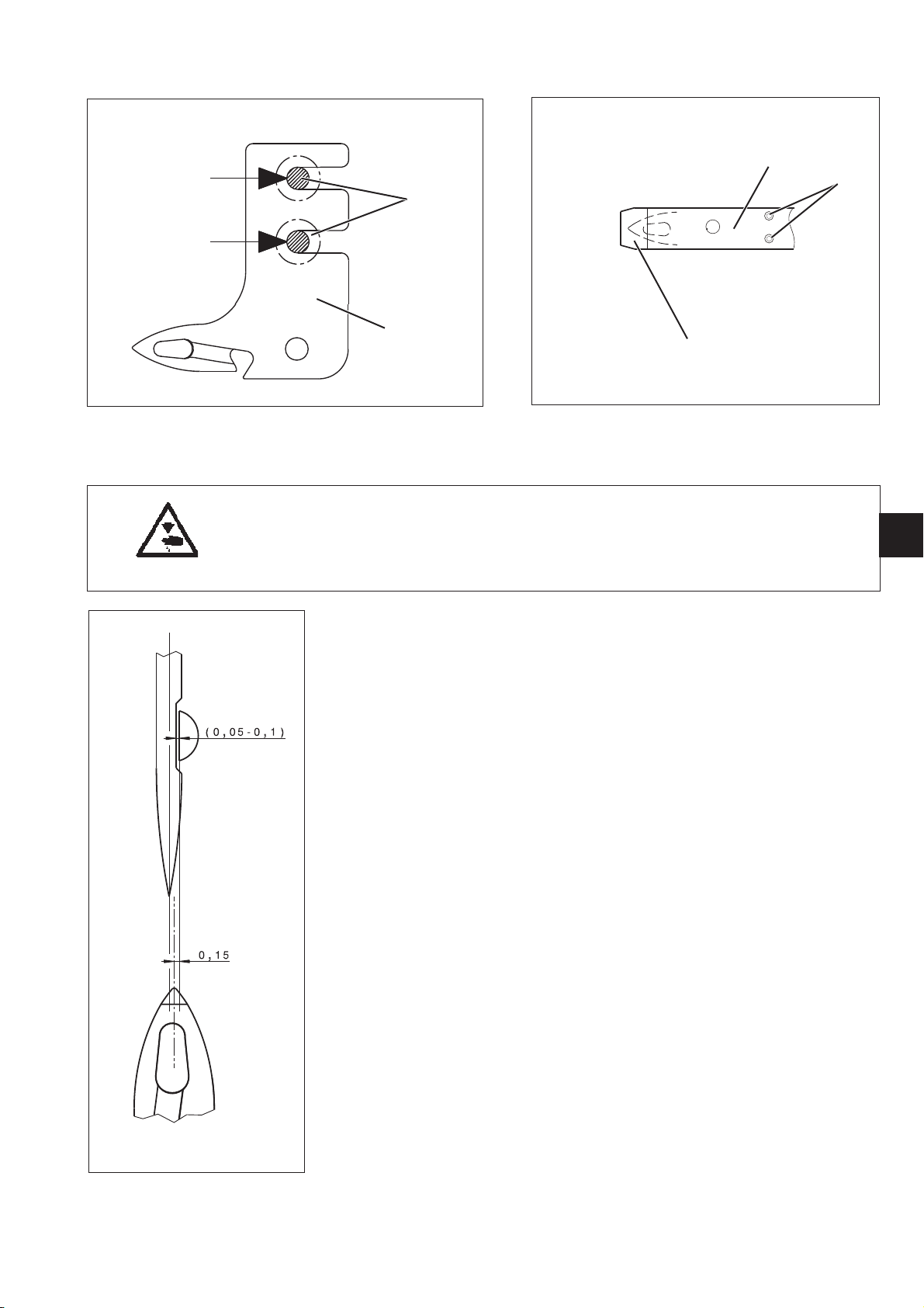
7.2 Hooked knife
4
1
2
3
Caution: Risk of injury!
Turn off the main switch.
Check and set the hooked knife only with the sewing machine
switched off.
5
GB
Standard checking
The hooked knife 2 must lie against both screws 1 in the direction of
the arrow.
Hereby the cut through the tip of the hooked knife is ensured.
At the same time, the tip of the hooked knife has the correct position in
the axial direction.
A virtual line lengthening the hooked knife point will then be in the
center between the needle center and the hook tip.
Correction
–
Unwind the clamping pressure of the fixed knife against the hooked
knife through loosening the set screws 5.
–
Manually swivel in the hooked knife 2.
–
Loosen the fastening screws 1 of the hooked knife.
–
Shift the hooked knife 2 against the fastening screws 1 in the
direction of the arrow.
–
Tighten the fastening screws 1 again.
–
Check the eccentrically rising of the hooked knife.
–
Set the counter knife (see chapter 7.3).
27
Page 32

7.3 Setting the cutting pressure
321
Caution: Risk of injury!
Turn off the main switch.
Check and set the cutting pressure only with the sewing machine
switched off.
1
4
When performing setting tasks within the hook area, both knives
should preferably remain in the machine. Thus avoiding unnecessary
adjustment work.
Standard checking
The threads must reliably be cut with the lowest pressure possible.
Low cutting pressure reduces the wear!
Two of the thickest threads to be sewn must reliably be c ut
simultaneously.
Correction
–
Turn back the cutting pressure screws 1.
–
Swivel forwards the hooked knife 3.
–
Set the fixed knife 2 against the hooked knife 3 by screwing in the
cutting pressure screws 1.
–
Alternately lay the thread to be cut to the right and to the left.
–
Adjust appropriate cutting pressure screw.
–
If the return spring 4 does no longer bring the cutting mechanism to
its starting position, then the cutting pressure is too high!
The fixed knife must be replaced against a new one.
Please note!
A regrinding of the fixed knife is allowed to a minor degree!
If the knife loses a lot of its length, it can no longer cut.
A new setting of the hooked knife cannot compensate it.
28
Page 33

8. Setting the bobbin winder
8.1 Switching off the bobbin winder
2
1
3
4
+
+
-
Caution: Risk of injury!
Turnthemainswitchoff!
Check and set the bobbin winder only with the sewing machine
switched off.
GB
Standard checking
The bobbin winder should stop automatically, when the bobbin is filled
up to approx. 0.5 mm below the edge of the bobbin.
Correction
1. Minor changes of the bobbin wind-on quantity
–
Bend the thread guide tab 3.
2. Major changes of the bobbin wind-on quantity
–
Loosen the screw 2.
–
Adjust the thread guide tab 3.
In the direction of the arrow - :
less quantity
In the direction of the arrow + :
more quantity
–
Fasten the screw 2 again.
After a removal of the release lever 4, a pre-setting at the clamping
screw 1 must be done first.
ATTENTION RISK OF BREAKAGE!
Lift the sewing foot with the hand lever and remove the bobbin case
from the hook when winding without sewing.
29
Page 34

8.2 Winding form of the bobbin
4
1
3
2
Caution: Risk of injury!
Turnthemainswitchoff!
Check and set the bobbin winder only with the sewing machine
switched off.
8.3 Winding tightness
Standard checking
The winding form depends on the position of the gap 3 between both
thread guide sleeves. It should be cylindrical in order to evenly fill the
bobbin to its whole width.
In the case a the gap is set too low.
·
In the case c the gap is set too high.
·
Correction
–
Loosen the knurled nut 2.
–
Shift the guide bolt 1 axially through turning it with a screw driver.
Make sure not to alter the position of the adjusting knob 4.
–
Tighten the knurled nut 2 again.
Standard checking
A minimum pretension of the bobbin thread is required in order to get a
regular winding result (accurate winding on the bobbin).
This depends on the sliding qualities and the thickness of the thread.
A too strong tightness of the winding is favourable to the formation of
ruffs.
30
Correction
–
Turn the adjusting knob 4 clockwise = increase the pretension
–
Turn the adjusting knob 4 counter-clockwise = decrease the
pretension
Page 35

9. Filling up oil (gear box)
Caution: Risk of injury!
Oil can cause skin eruptions.
Avoid protracted contact with the skin.
In event of contact, thoroughly wash the affected area.
1
2
GB
ATTENTION !
The handling and disposal of mineral oils is subject to legal regulation.
Deliver used oil to an authorised collection point.
Protect your environment.
Take care not to spill oil.
Rule
Check the oil level with the machine tilted to the back.
The machine head rest on the machine head support and the surface
of the base plate is vertical to the table top.
The filling up check is intended for lifetime.
Upon delivery the oil level is in the middle of the monitor window 1.
Filling up oil (gear box)
–
Tilt the machine backwards.
–
Unscrew the plug screw 2 with its seal ring.
–
Fill up with DA 32 oil up to the middle of the monitor window 1.
For this purpose use a hose connected to a oil can nozzle.
Oil grade being used
Special lubricating oil DA 32 / resistant to light and ageing resistant /
high wear protection
Viscosity / 40°C: 32 mm²/s - ISO VG32
The oil can be obtained from Dürkopp Adler under the part number
9047 000032 in a 0.9l container.
31
Page 36

10. Hook lubrication
2
(only subclasses with oil lubricated hook)
1
Caution: Risk of injury!
Oil can cause skin eruptions.
Avoid protracted contact with the skin.
In event of contact, thoroughly wash the affected area.
ATTENTION !
The handling and disposal of mineral oils is subject to legal regulation.
Deliver used oil to an authorised collection point.
Protect your environment.
Take care not to spill oil.
Maintenance work Explanation Operating
to be carried out hours
Lubrication of
the hook
The oil level shall not fall below the MIN level of the oil
reservoir 1.
Fill up the DA 10 oil through the bore hole 2 up to the
marking line “Max”.
Oil grade being used
Special lubricating oil DA 10 / colourless / resistant to light and ageing
resistant / high wear and corrosion protection
Viscosity / 40°C: 10 mm²/s - ISO VG10
The oil can be obtained from Dürkopp Adler with the following parts
numbers:
8
32
1 litre container 9047 000012
·
5 litre container 9047 000014
·
Please note !
In the machine equipped with an oil-free hook (subclass 281-140442)
no oil filling up is necessary.
Page 37

10.1 Setting the oil quantity for the hook
1
The hook lubrication is insured by the oil wick inside a s ilicone rubber
hose, going from the hook oil reservoir to the spray cone on the back of
the hook.
The oil quantity can be reduced through the adjustment screw 1.
By pressing the hose, the adjustment screw throttles the oil quantity for
the hook.
1
GB
Rule
Put a piece of paper instead of the throat plate above the throat plate
cutout, and sew with the machine with the maximum speed for 15 sec.
The paper should have a fine oil sprayed on it.
Correction
–
Remove the throat plate.
–
Remove the feed dog.
–
Take out the bobbin case.
–
Turn the adjustment screw 1.
Clockwise = less oil for the hook
Counter-clockwise = more oil for the hook
–
Fix the throat plate, the feed dog and the bobbin case again.
Please note:
The reduction of the desired oil flow-rate does not happen instantly
after the turning of the adjustment screw, this is because the residual
oil in the wick between the throttle and the hook needs to be used up
first.
A verification makes only sense if carried out a couple of hours later.
33
Page 38

11. Maintenance
Caution: Risk of injury!
Turnthemainswitchoff!
The maintenance of the sewing machine must only be done when the
machine is switched off.
The daily or weekly maintenance work (cleaning and oiling) to be
carried out by the operators of the sewing machine is described in the
operating instructions (part 1). It is only listed in the following table for
the sake of completeness.
Maintenance work to be carried out Operating hours
8 40 160 500
Sewing machine head
- Remove dust in the area under the throat plate .................... X
- Removedustfrombetweenthefeed dogelements................. X
(remove the throat plate)
- Remove dust in the area under the bobbin brake spring............. X
- Checkoillevel.................................................. X
- Check oil level in oil reservoir for the hook lubrication .............. X
- Check hook lubrication .......................................... X
- Checktoothedbelt.............................................. X
Sewing motor
- Cleanthemotoraeratorfilter .................................... X
34
Page 39

L1
L2
L3
N
PE
F
F
F
3x380-415V+N
50/60Hz
F
max 16A
L1
N
PE
L2
N
PE
L3
NPEPE
Terminal to three-phase
power supplies:
Anschluß an Drehstromnetze:
Several dc-drives must be
distributed evenly amog all phases.
Mehrere DC-Antriebe sind
1x220-240V 50/60Hz
gleichmäßig auf alle Phasen zu verteilen.
Power Switch
Netzschalter
9800 360104
BN
BU
GN-YE
Q0
L1 L
N1 N
BN
BU
BN
BU
GN-YE
L1
L2
L3
PE
F
L1L2PE
F
L1
L3
PE
F
L2
L34PE
1x220-240V 50/60Hz
PE
X0
L
N
1x 200-240V
50/60Hz
BN
BU
GN-YE
3x220-240V
50/60Hz
F
max 16A
LED1: 24V/70mA
LED2: 400mA
IN:
190-240V
50/60Hz
10VA
F1
M0,63A
9850 001083
OUT:
X1
GN
1
LED 1
YE
GY
PK,
WH
BN
2
3
4
1
2
3W
LED 2
BK
GY
RD
GY
WH
BN
T1
Z
9890 281001 B
LED 3W
sewing light
Nähleuchte
Z
9822 560000
H1
BU
BN
GN-YE
A2
Operation Box
Bedienfeld
C200: 9800 360105
Speed Control Unit
ext. Geber
9800 370003
A3
X10blue
1
2
3
4
X14
X11
1
X12
2
3
4
VT
5
BK
6
7
10
BU
11
12
13
RD
14
15
PK BN
16
17
18
RD-BU
19
20
26
YE
27
28
GY-PK
31
32
WH
33
GY
34
GN
35
BN
36
37
GN
1
BN
2
GY
3
4
WH
5
YE
9
shield
WH
9870 281000
Encoder cpl.
9850 281002
WH
BN
GN
YE
GY
(*1)
9870 001117 CN
1
2
3
M1.1
4
5
+5V
N1
L1
PE
blue
0V_Logic
RM_IN
NHT_IN
KNEE_SWITCH_IN
LSP_IN
RU/RAB_IN
+24V/+30V
+24V/+30V
0V
+24V=
FW_OUT
LED_OUT
+24V/+30V
RA_OUT
FL_OUT
FA/FS_OUT
FA_OUT
A PH
B PH
IND.
VCC
VCC
GND
Sewing Machine
Nähmaschine
281-140342
281-140442
WH
BN
GN
YE
GY
PK
BU
RD
BK
VT
GY-PK
RD-BU
X2
1
+24V/+30V
2
FA/FS_OUT
3
FL_OUT
4
FW_OUT
5
RA_OUT
6
+24V TRANSF.
7
LSP_IN
8
RU/RAB_IN
9
NHT_IN
10
RM_IN
11
LED_OUT
12
0V
X1
S4
PCB cpl. 9850 281001
Leiterplatte k
A4
9870 281002
X3
WH
RM_IN
0V
1
BN
2
GN
3
YE
4
GY
5
PK
6
7
8
9
BU
10
S1
FA/FS_OUT4
FL_OUT5
V1
1N4007
V2
1N4007
FW_OUT6
+24V/+30V
RU/RAB_IN
RA_OUT7
+24V_LED
LED_OUT
NHT_IN
LSP_IN
+24V/+30V3
X1
WH
1
BN
2
GN
3
YE
4
GY
5
6
PK
7
BU
8
PCB cpl., keypad
9850 281003
S1
V1
LED sewing light ON/OFF
S1
RM
S2
NHT
S3
RU/RAB
V1
LED yellow
S2
R1
4K7
1
0V
+24V_LED
S4
S3
2
(*1)
1
1
5
2
2
6
7
3
8
8
1
2
A1
Control Unit
Steuergerät
HVP20-4
9800 370005
Z
= Optional Equipment
Sonderausstattung
white
X13 white
PE
U
V
W
1
2
3
4
Ground
GN
WH
BN
YE
9870 001409 CN
d
c
b
a
No.
Modifications/
Date Signature
WH
YE
BN
GN
shield
Confirmation
WH
YE
BN
M1
Sewing Motor
Nähmotor
drawing valid from April 2009
D PPÜRK O
ADLER AG
Bie le f el d
www.duerkopp-adler.com
Date/
Designer/
Checker/
Release/
Y1.2
2008-09-08
Czytrich
Priemer
/0145 05
Y1.1
Y2
Z
Cl. 281-140342; -140442
Control Unit HVP-20-4-28-CE
triple keypad with LED-sewinglight
Y3
Y4
A6
Switch cpl., LED
9880 281000
Denomination
PCB cpl., LED
9850 281004
connection diagram
Part Number/
9890 281001 B
V
Page
/1 2
Page 40

L1
L2
L3
N
PE
F
F
F
3x380-415V+N
50/60Hz
F
max 16A
L1
N
PE
L2
N
PE
L3
NPEPE
Terminal to three-phase
power supplies:
Anschluß an Drehstromnetze:
Several dc-drives must be
distributed evenly amog all phases.
Mehrere DC-Antriebe sind
1x220-240V 50/60Hz
gleichmäßig auf alle Phasen zu verteilen.
Power Switch
Netzschalter
9800 360104
BN
BU
GN-YE
Q0
L1 L
N1 N
BN
BU
BN
BU
GN-YE
L1
L2
L3
PE
F
L1L2PE
F
L1
L3
PE
F
L2
L34PE
1x220-240V 50/60Hz
PE
X0
L
N
1x 200-240V
50/60Hz
BN
BU
GN-YE
3x220-240V
50/60Hz
F
max 16A
LED1: 24V/70mA
LED2: 400mA
IN:
190-240V
50/60Hz
10VA
F1
M0,63A
9850 001083
OUT:
X1
GN
1
LED 1
YE
GY
PK
WH
BN
2
3
4
1
2
3W
LED 2
BK
GY
RD
GY
T1
Z
9890 281001 B
LED 3W
sewing light
Nähleuchte
Z
9822 560000
H1
BU
BN
GN-YE
A2
Operation Box
Bedienfeld
C200: 9800 360105
Speed Control Unit
ext. Geber
9800 370003
A3
X10blue
1
2
3
4
X14
X11
+5V
N1
L1
PE
blue
0V_Logic
RM_IN
NHT_IN
KNEE_SWITCH_IN
LSP_IN
RU/RAB_IN
+24V/+30V
+24V/+30V
0V
+24V=
FW_OUT
LED_OUT
+24V/+30V
RA_OUT
FL_OUT
FA/FS_OUT
FA_OUT
X12
A PH
B PH
IND.
VCC
VCC
GND
GY-PK
1
2
3
PK
4
VT
5
BK
6
7
10
BU
11
12
13
RD
14
15
16
17
18
RD-BU
19
20
26
YE
27
28
31
32
WH
33
GY
34
GN
35
36
BN
37
GN
1
BN
2
GY
3
4
WH
5
YE
9
shield
9870 281000 CN
Encoder cpl.
9850 281002
WH
BN
GN
YE
GY
(*1)
9870 001117 CN
1
2
3
M1.1
4
5
Sewing Machine
Nähmaschine
281-140342
281-140442
WH
BN
GN
YE
GY
PK
BU
RD
BK
VT
GY-PK
RD-BU
X2
1
2
3
4
5
6
7
8
9
10
11
12
+24V/+30V
FA_OUT
FL_OUT
FW_OUT
RA_OUT
OV Logic
LSP_IN
RU/RAB_IN
NHT_IN
RM_IN
AS
0V
X1
S1
PCB cpl. 9850 281001 CN
Leiterplatte k
A4
R1
100R
R2
2K7
+24V/+30V
+24V/+30V
RM_IN
GND/LED
NHT_IN
RU/RAB_IN
AS
0V Logic
LSP_IN
0V
X3
4
10
9870 281001 CN
1
2
3
5
6
7
8
9
WH
BN
GN
YE
pushbutton
Taster
0281 350354
BN
GN
YE
yellow
WH
A5
S2
41
V1
Power
ON
V1
(*1)
FA_OUT4
FL_OUT5
FW_OUT6
RA_OUT7
+24V/+30V3
S2
1
1
5
2
2
6
7
3
8
8
A1
Control Unit
Steuergerät
HVP20-4
9800 370005
Z
= Optional Equipment
Sonderausstattung
white
X13 white
PE
U
V
W
1
2
3
4
Ground
GN
WH
BN
YE
9870 001409 CN
d
c
b
a
No.
Modifications/
Date Signature
WH
YE
BN
GN
shield
Confirmation
WH
YE
BN
M1
Sewing Motor
Nähmotor
drawing valid to March 2009
D PPÜRK O
ADLER AG
Bie le f el d
www.duerkopp-adler.com
Date/
Designer/
Checker/
Release/
Y1.2
2008-09-08
Czytrich
Priemer
/0145 05
Y1.1
Y2
Z
Cl. 281-140342; -140442
Control Unit HVP-20-4-28-CE
and single pushbutton
Y3
Y4
Denomination
connection diagram
Part Number/
9890 281001 B
Page
/2 2
 Loading...