

Page 1

100/68
Universal
Piped-Pocket-Sewing unit
Operating instructions
Assembly instructions
Service instructions
Programming instructions
1
2
3
4
Ausgabe / Edition: 11/2007 Printed in Federal Republic of Germany Teile-Nr.:/Part-No.:DOC000045
Page 2

Page 3

Foreword
This instruction manual is intended to help the user to become familiar
with the machine and take advantage of its application possibilities in
accordance with the recommendations.
The instruction manual contains important information on how to
operate the machine securely, properly and economically. Observation
of the instructions eliminates danger, reduces costs for repair and
down-times, and increases the reliability and ute of the machine.
The instruction manual is intended to complement existing national
accident prevention and environment protection regulations.
The instruction manual must always be available at the
machine/sewing unit.
The instruction manual must be read and applied by any person that is
authorized to work on the machine/sewing unit. This means:
Operation, including equipping, troubleshooting during the work cycle,
removing of fabric waste,
–
Service (maintenance, inspection, repair) and/or
–
Transport.
The user also has to assure that only authorized personnel work on the
machine.
The user is obliged to check the machine at least once per shift for
apparent damages and to immediatly report any changes (including the
performance in service), which impair the safety.
The user company must ensure that the machine is only operated in
perfect working order.
Never remove or disable any safety devices.
If safety devices need to be removed for equipping, repairing or
maintaining, the safety devices must be remounted directly after
completion of the maintenance and repair work.
Unauthorized modification of the machine rules out liability of the
manufacturer for damage resulting from this.
Observe all safety and danger recommendations on the machine/unit!
The yellow-and-black striped surfaces designate permanend danger
areas, eg danger of squashing, cutting, shearing or collision.
Besides the recommendations in this instruction manual also observe
the general safety and accident prevention regulations!
Page 4

General safety instructions
The non-observance ot the following satety instructions can
cause bodily injuries or damages to the machine.
1. The machine must only be commissioned in full knowledge of the
2. Before putting into service also read the safety rules and
3. The machine must be used only for the purpose intended. Use of
4. When gauge parts are exchanged (e.g. needle, presser foot,
instruction book and operated by persons with appropriate
training.
instructions of the motor supplier.
the machine without the safety devices is not permitted. Observe
all the relevant safety regulations.
needle plate, feed dog and bobbin) when threading, when the
workplace is left, and during service work, the machine must be
disconnected from the mains by switching off the master switch or
disconnecting the mains plug.
5. Daily servicing work must be carried out only by appropriately
trained persons.
6. Repairs, conversion and special maintenance work must only be
carried out by technicians or persons with appropriate training.
7. For service or repair work on pneumatic systems, disconnect the
machine from the compressed air supply system (max. 7-10 bar).
Before disconnecting, reduce the pressure of the maintenance
unit.
Exceptions to this are only adjustments and functions checks
made by appropriately trained technicians.
8. Work on the electrical equipment must be carried out only by
electricians or appropriately trained persons.
9. Work on parts and systems under electric current is not permitted,
except as specified in regulations DIN VDE 0105.
10. Conversion or changes to the machine must be authorized by us
and made only in adherence to all safety regulations.
11. For repairs, only replacement parts approved by us must be used.
12. Commissioning of the sewing head is prohibited until such time as
the entire sewing unit is found to comply with EC directives.
It is absolutely necessary to to respect
the safety instructions marked by these signs.
Danger of bodily injuries !
Please note also the general safty instructions.
Page 5

Index Page:
Part 1: Operating instructions 100/68
1. Description of product ..............................................3
1.1 Description of proper use .............................................3
1.2 Brief description...................................................3
1.3 Technical data ....................................................4
2. Operating ......................................................5
2.1 Swivelling the folding station aside .......................................5
2.2 Removing the fabric sliding sheet ........................................6
2.3 Needles and threads ................................................7
2.4 Threading the needle thread ...........................................9
2.5 Winding up the hook thread ...........................................10
2.6 Remaining thread monitor ............................................11
2.7 Slanted pocket opening (optional) .......................................12
2.7.1 Swivelling the corner knife station in and out .................................12
1
3. Switching on - Starting the sewing process - Program stop - Switching off ...........14
3.1 Switching on ....................................................14
3.2 Reference position ................................................15
3.3 Starting the sewing process ...........................................15
3.4 Program stop....................................................16
3.5 Switching off ....................................................16
4. Working methods ................................................17
4.1 Working method “Production of trousers” ...................................18
4.2 Working method “Breast welt pocket” .....................................20
5. Quick clamp adjustment and folder monitoring .............................22
6. Function and operation of the optional equipment ..............................23
6.1 Tape feeding unit with automatic trimming and tape monitor........................23
6.2 Endless zipper device ..............................................26
7. Maintenance....................................................27
7.1 Cleaning ......................................................27
7.2 Oil level control ..................................................28
Page 6

2
Page 7

1. Description of product
1.1 Description of proper use
The Beisler 100/68 is a sewing unit which can properly be used for
sewing light to medium-weight material. Such material is, as a rule,
made of textile fibres or leather. These materials are used in the
garment industry.
In general only dry material must be sewn on this machine. The
material must not contain any hard objects.
The seam is generally made with core thread, polyester fibre
or cotton threads.
The dimensions for needle and hook threads can be taken from the
table in chapter 2.4.
Before using any other threads it is necessary to estimate the
consequential dangers and to take the respective safety measures, if
required.
This sewing unit must only be installed and operated in dry and
well-kept rooms. If the sewing unit is used in other rooms, which are
not dry and well-kept, further measures to be agreed upon may
become necessary (see EN 60204-31 : 1999).
We, as manufacturer of industrial sewing machines, assume that at
least semi-skilled operating personnel will be working on our products
so that all usual operations and, where applicable, their risks are
presumed to be known.
1
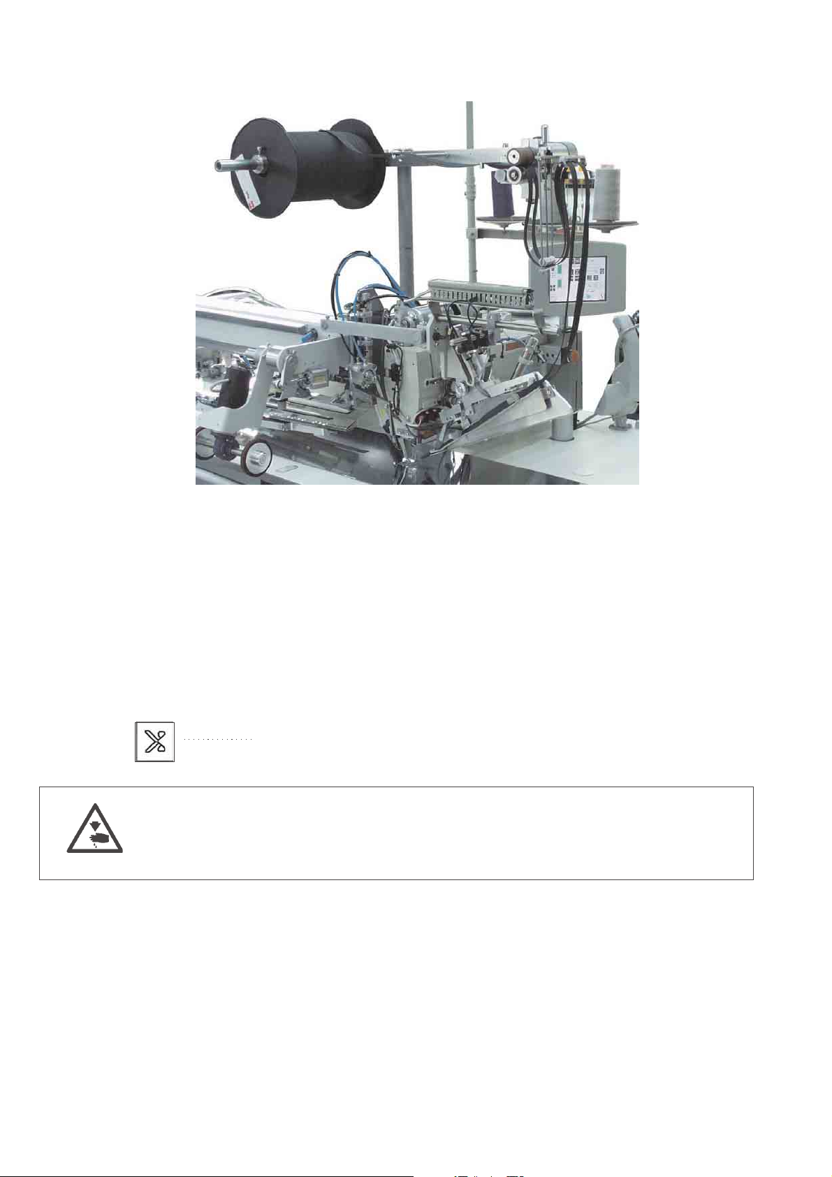
1.2 Brief description
The Beisler 100/68 is a sewing unit for automated runstitching of piped
pocket, flap pocket and welt pocket openings with rectangular or
slanted pocket corners.
The slanted pocket corners result from the offset of the two seam rows.
It is possible to sew different slants at the seam beginning and at the
seam end.
Depending on the working method various feeding devices, corner
knife stations and optional equipment are used.
Machine head
–
Twin needle lockstitch version
–
Needle bars can be switched/engaged jointly or separately
–
Vertical hook
–
Externally driven centre knife, speed and release time/switching
time programmable
–
Thread trimming device for needle and hook threads
–
Monitor for the needle threads
–
Photoelectric remaining thread monitor for the hook threads
–
DC direct sewing drive
Step motors for the material feed and the length adjustment of the
corner trimming device
The step motor technology allows short machine times and guarantees
an absolutely precise material feed and accurate corner incisions.
3
Page 8

Thus, it contributes to a pocket quality unrivalled as yet combined with
high productivity.
New control generation “DAC III”
The graphic user guidance is exclusively effected by internationally
comprehensible symbols and texts in the language of the respective
country.
The various symbols are arranged in groups within the menu structure
of the sewing and test programs.
The easy operation allows short training times.
20 storage locations with each 6 seam programs are available. Thus it
is possible to generate and store up to 6 different seam programs per
storage location.
6 seam programs can be allocated to every storage location in any
desired order which can be sewn in succession.
All slants to be processed can be programmed by the operator via
parameters.
The comprehensive test and monitoring system MULTITEST is
integrated in the DAC.
A microcomputer does the control tasks, supervises the sewing
process and indicates operating errors and malfunctions in the display.
Optional equipment
Due to a flexible system of optional equipment the sewing unit can be
optimally adapted to the respective application at low cost.
Sewing equipment and folders
Please see parts list of cl. 100/68 for details concerning sewing
equipment and folders for the various applications or contact the
Beisler company.
1.3 Technical data
Needle system: 2134-35
Needle distance: 8, 10, 12, 14, 16,
20, 22, 24, 26, 30 mm
Needle size: Nm 80 to Nm110
Threads: see table chapter 2.3
Stitch type: twin needle lockstitch
Speed: max. 3,000 r/ min
Stitch length: min. 0.5 to 3.0 mm
Number of condensed stitches: 1 - 20
Number of bartack stitches: 0 - 20
Stitch length condensed
stitches/ bartacks 0.5 - 3.0 mm
Pocket length: max. 250mm
Operating pressure: 6 bar
Air consumption: approx. 6 NL per working cycle
Rated voltage: 1 x 230 V / 50/60 Hz
Dimensions: 1750 x 1450 x 1700 mm (L xWxH)
Working height: 830 mm
(upper table top edge)
Weight: 270 kg
4
Page 9
2. Operating
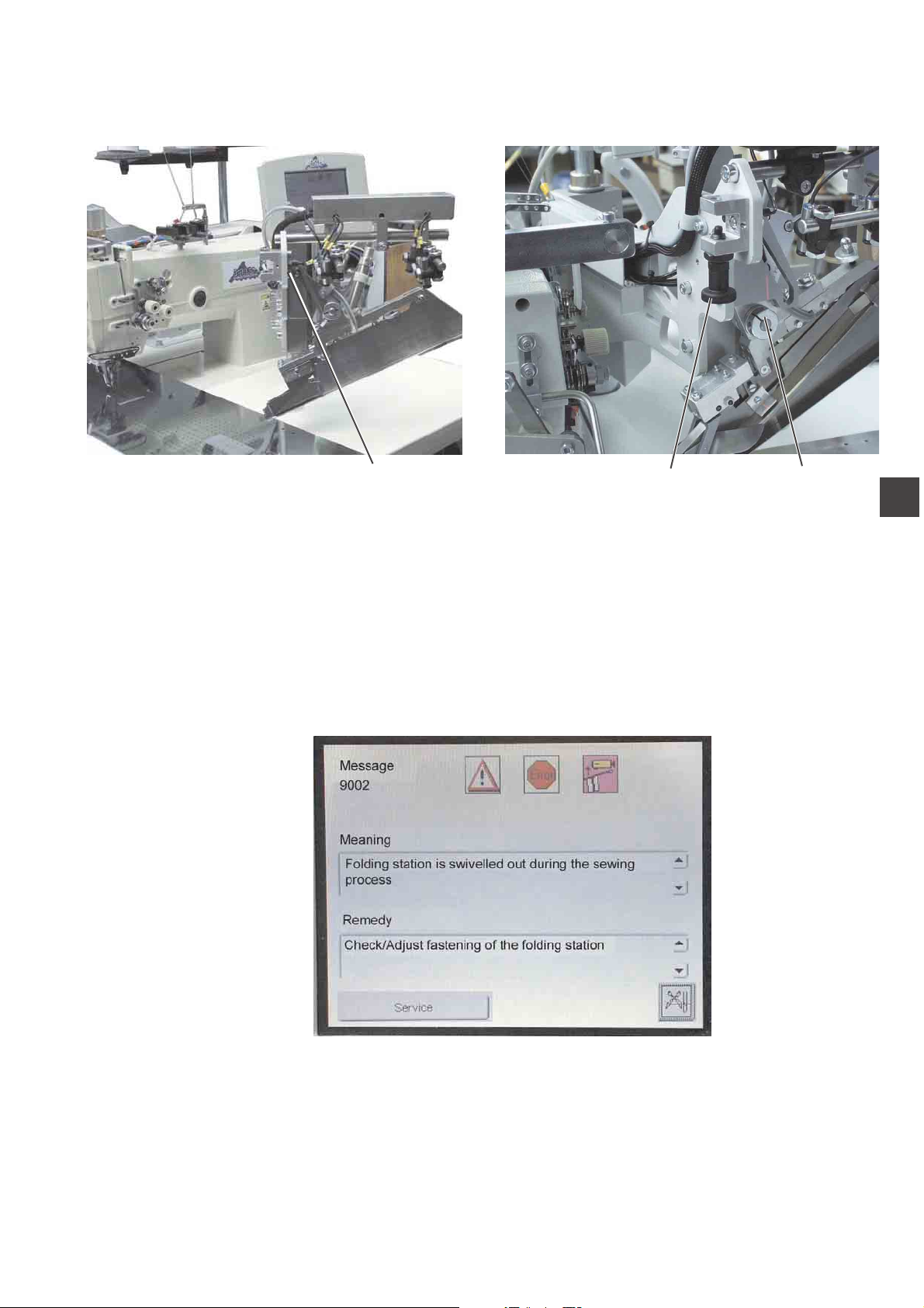
2.1 Swivelling the folding station aside
1
For work at the sewing point (threading the needle threads, needle
change etc.) the entire folding station with folder and laser lamps can
be swivelled to the right.
–
Swivel the entire folding station 1 with folder to the right.
The sewing point is freely accessible.
Note:
When the sewing unit is switched on a
safety message is indicated in the display of the control panel.
32
1
Folding station swivelled out
Swivelling the folding station back
–
Swivel the folding station 1 back.
ATTENTION !
After having been swivelled back the folding station must snap in
catch 2.
5
Page 10
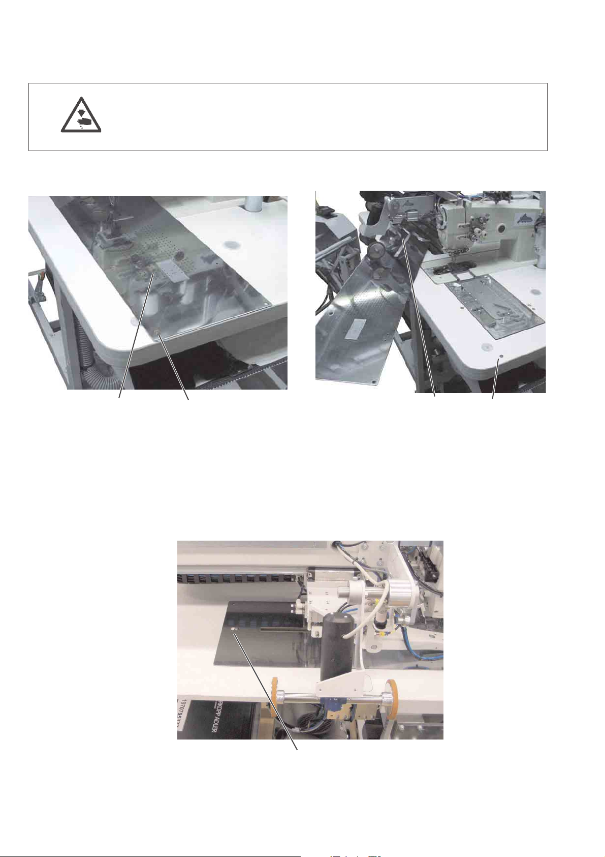
2.2 Removing the fabric sliding sheet
Caution: Risk of injury!
Switch the main switch off.
Remove the fabric sliding sheet only with the sewing unit switched off.
–
Switch the main switch off
21
For changing the hook thread bobbins:
–
Lift the fabric sliding sheet 2 at/with the pin 1 and swivel it to the
left.
For complete removing (for maintenance work and adjustments):
–
Lift the fabric sliding sheet at the hind pin 3c completely.
31
3
6
Page 11

2.3 Needles and threads
Needle system: 2134-85
Recommended
needle size: Nm 90 for thin material
Nm 100 for medium-weight material
Nm 110 for heavy-weight material
High sewing security and good sewability are achieved with the
following
core threads:
–
Two-ply polyester endless polyester core-spun
(e.g. Epic Poly-Poly, Rasant x, Saba C, ...)
–
Two-ply polyester endless cotton core-spun
(e.g. Frikka, Koban, Rasant, ...)
If these threads are not available, the polyester fibre or cotton threads
listed in the table can also be sewn.
Often two-ply core threads are offered by the thread manufacturers
with the same designation as three-ply polyester fibre threads
(3cyl.-spun).This causes uncertainty with regard to twisting and thread
thickness.
When in doubt, unravel the thread and check whether it is twisted 2- or
3-ply.
The label no. 120 on the thread reel of a core thread corresponds e.g.
to the thread size Nm 80/2 (see table values in brackets).
In case of monofilament threads you can use needle threads and hook
threads of the same thickness. The best results are achieved with soft
and elastic threads (software) of the thread thickness 130 Denier.
1
Recommended thread thicknesses:
Needle size Core thread Core thread
Nm
Needle thread Hook thread Needle thread Hook thread
Polyester Polyester Polyester Cotton
endless core-spun endless core-spun
Label No. Label No. Label No. Label No.
90 120 (Nm 80/2) 120 (Nm 80/2) 120 (Nm 80/2) 120 (Nm 80/2)
100 100 (Nm 65/2) 100 (Nm 65/2) 100 (Nm 65/2) 100 (Nm 65/2)
110 75 (Nm 50/2) 75 (Nm 50/2) 75 (Nm 50/2) 75 (Nm 50/2)
Needle size Polyester fibre thre-ad Cotton thread
Nm (3cyl.-spun)
Needle thread Hook thread Needle thread Hook thread
90 Nm 80/3-120/3 Nm 80/3-120/3 Ne
100 Nm 70/3-100/3 Nm 70/3-100/3 Ne
110 Nm 50/3-80/3 Nm 50/3-80/3 Ne
50/3-70/3 NeB50/3-70/3
B
40/3-60/3 NeB40/3-60/3
B
40/4-60/4 NeB40/4-60/4
B
7
Page 12
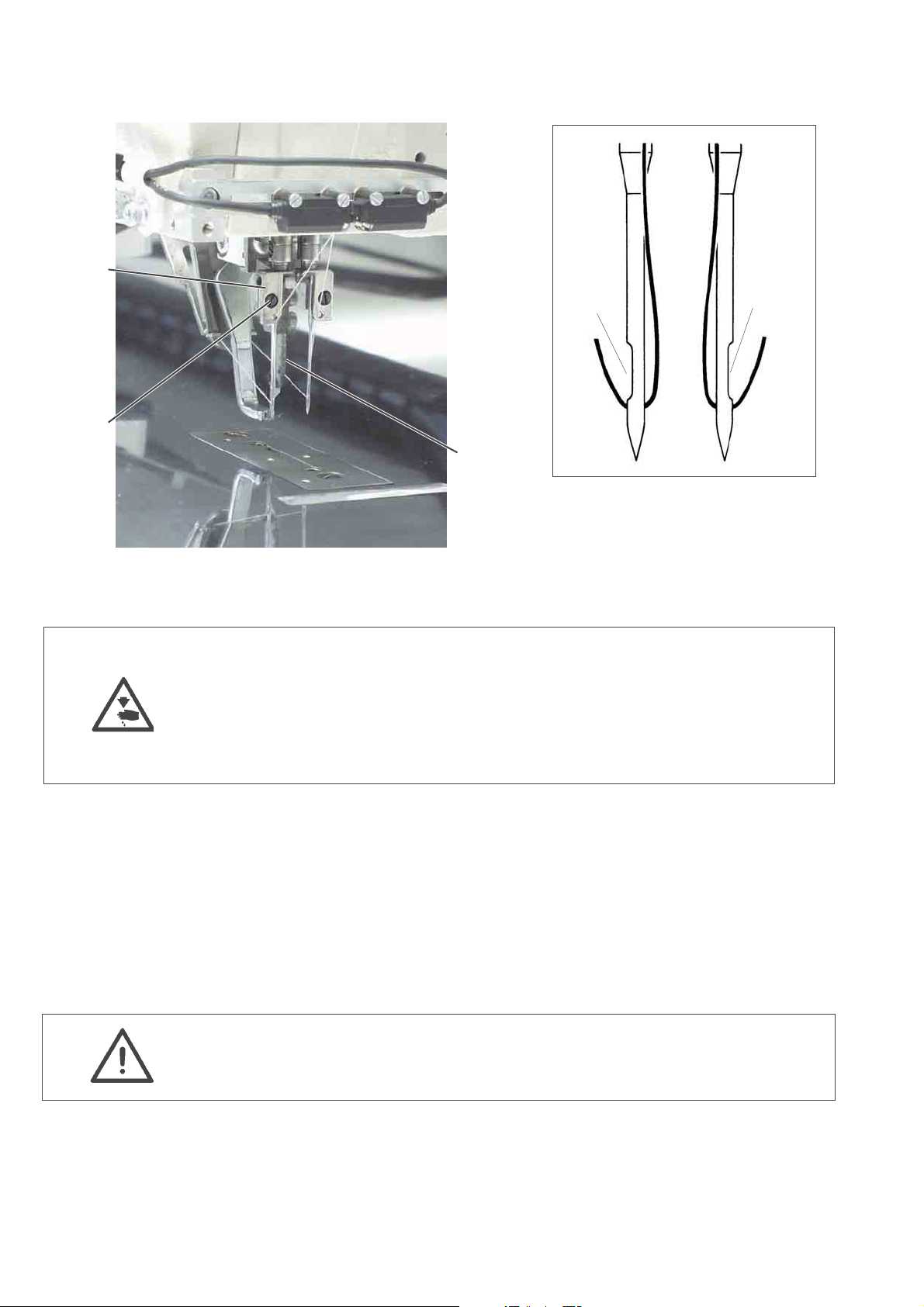
Needle change
1
4
5
2
3
Caution: Risk of injury!
Switch the main switch off.
Change the needles only when the main switch is switched off.
Risk of cuts!
Do not reach into the area of the centre knife 3 when changing the
needles.
–
Swivel the folding station aside (see chapter 2.1)
The needles are freely accessible.
–
Loosen screw 2 and remove needle from needle holder 1.
–
Push a new needle into the drill-hole of needle holder 1 as far as it
will go.
ATTENTION!
Seen from the operator’s side of the sewing unit the hollow groove
4 of the left needle must point to the left and the hollow groove 5 of
the right neele to the right (see sketch).
–
Tighten screw 2.
ATTENTION!
After the changeover to another needle size the needle protection at
the hook has to be readjusted (see service instructions).
8
Page 13
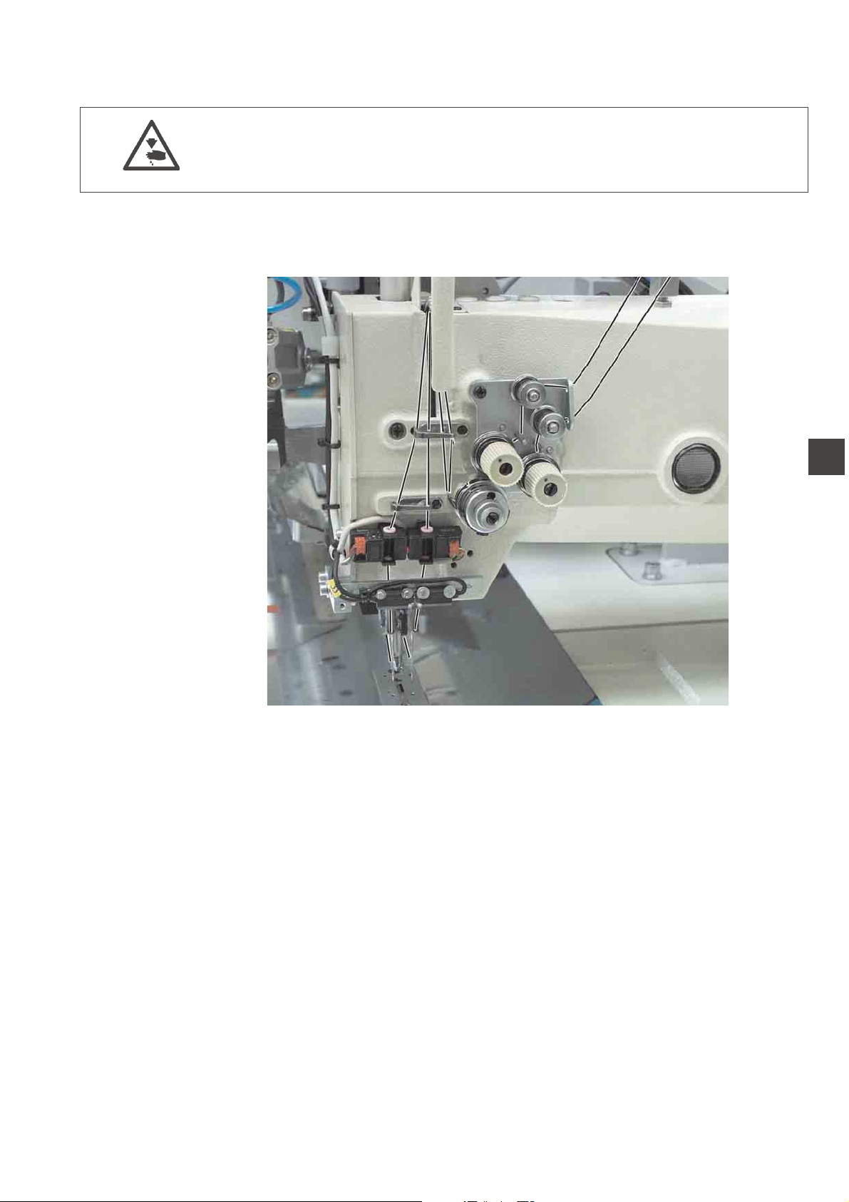
2.4 Threading the needle thread
Caution: Risk of injury!
Switch the main switch off.
Thread the needle threads only with the sewing unit switched off.
See the illustration for threading the needle threads.
1
9
Page 14
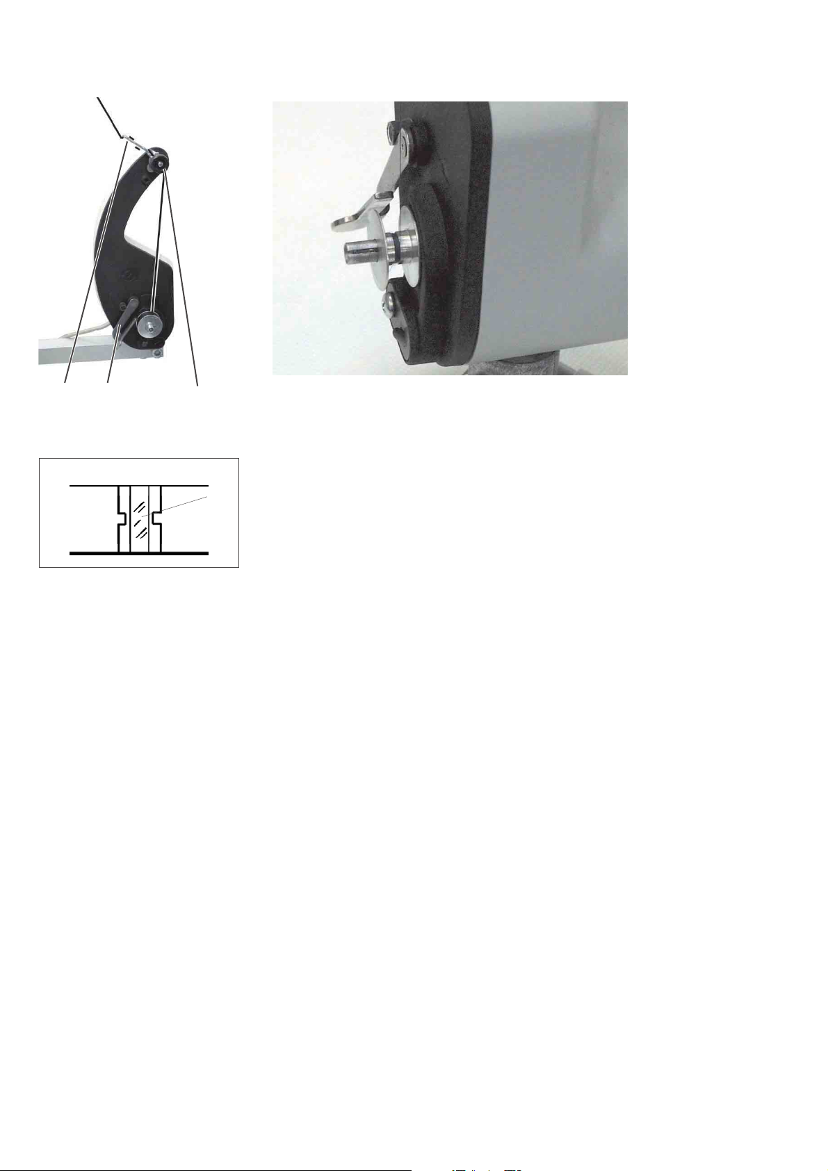
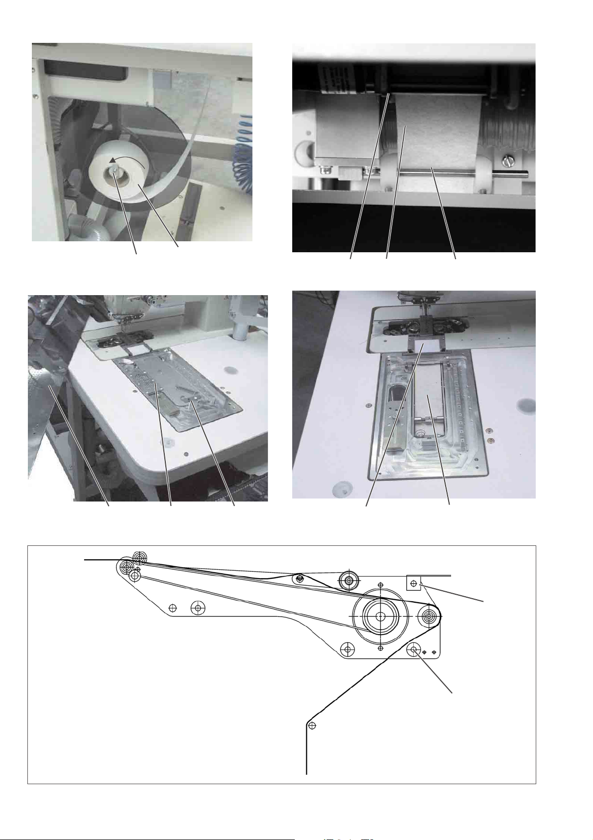
2.5 Winding up the hook thread
32 1
The separate winder allows to wind up up the hook threads
independent of the sewing process.
4
–
–
–
–
–
–
–
Remove thread remainders from the bobbin hubs before winding
up.
Put the thread reel on the thread reel holder.
Thread the thread through the drill-hole 1 of the unwinding arm.
Guide the thread through the guide 3.
Guide the thread through the bobbin thread tension 1.
Prewind the thread in the central supply groove of the bobbin hub
in clockwise direction.
The full supply groove guarantees a secure winding start, even in
case of monofilament threads.
With the thread supply in the supply groove it is ensured that the
pocket opening can be safely finished after the remaining thread
monitor has produced the message “bobbin empty”.
The reflecting surface 4 of the bobbin hub has to be kept clean.
Press the bobbin retainer 2 against the bobbin hub.
The winder starts.
After reaching the set bobbin filling quantity the winder stops
automatically.
See the service instructions for setting the bobbin filling quantity.
10
Page 15
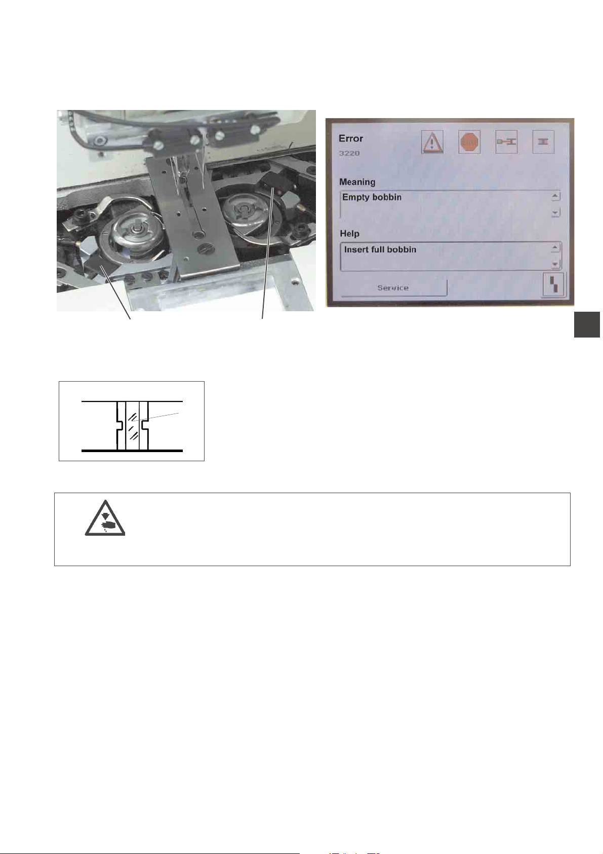
2.6 Remaining thread monitor
The remaining thread monitor supervises the left and right hook thread
bobbin with the infrared reflected light barriers 1 and 2.
21
–
When the bobbin is empty, the light beam emitted by light barrier 1
or 2 is reflected at the free reflecting surface 3 of the bobbin hub.
–
The display of the control unit indicates the message shown in the
right picture.
–
3
The remaining thread in the supply groove of the bobbin hub
guarantees that the pocket opening is safely finished.
The transport carriage stops in its rear end position.
Caution: Risk of injury!
Switch the main switch off.
Clean the lenses of the light barriers only with the sewing unit
switched off.
–
Switch the main switch off.
–
When changing the bobbin always clean the lenses of the light
barrier with a soft cloth.
–
Switch the main switch on.
–
Start the new sewing process.
1
11
Page 16
2.7 Slanted pocket opening (optional)
The 100/68 is optionally equipped with an automatic corner knife
station guaranteeing a precise incision of the corners of slanted
pockets.
For this purpose the machine head is equipped with disengageable
needle bars.
Corner knife station
The adjustment of the corner knives as to the pocket length is
programmable and is realized by a step motor.
The slanted pocket corners result from the offset of the two seam rows
programmable in steps of 1 mm.
The programmable pocket corner incision - adjustable via two step
motors - is freely selectable for the seam beginning and the seam end
and amounts to max. +/- 10 mm in relation to the second seam.
The lateral distance of the corner knives to the seam is manually
adjustable.
The whole unit can be folded out for adjusting and servicing.
2.7.1 Swivelling the corner knife station in and out
12
321
The corner knife station 1 can be swivelled out completely.
Caution: Risk of injury!
Switch the main switch off.
Swivel the corner knife station out only with the sewing unit
switched off.
Swivelling the corner knife station out
–
Push the rear corner knife support 3 (seam beginning) to the left.
–
Pull catch 2 down.
–
Swivel the corner knife station 1 to the left.
The knives are accessible for adjusting and servicing.
1
Page 17
21
Swivelling the corner knife station in
–
Swivel the corner knife station 1 back under the sewing unit.
–
Pull catch 2 down.
–
Swivel the corner knife station 1 in completely.
–
Release catch 2.
ATTENTION: Risk of breakage!
The holder 2 must snap in audibly.
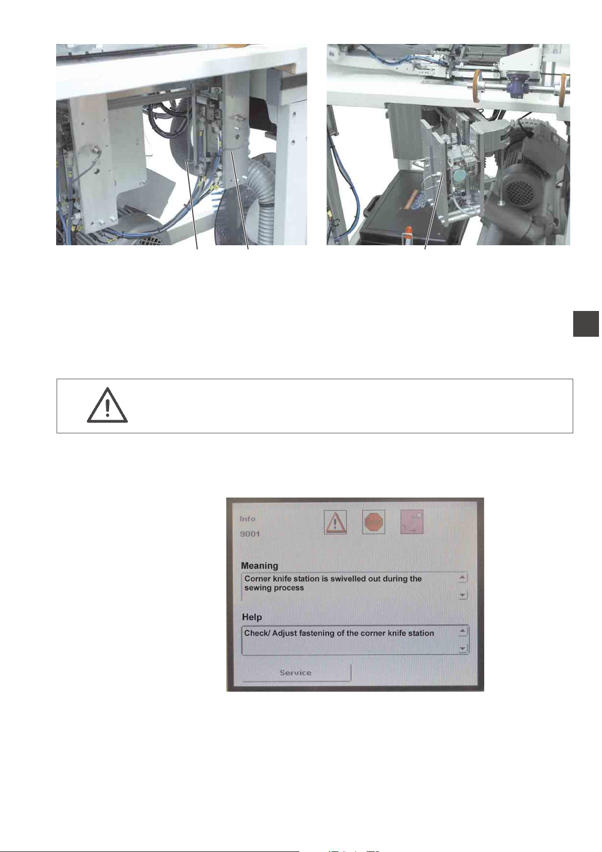
Note:
If the corner knife station is swivelled out with the sewing unit switched
on, the following message appears:
1
1
13
Page 18
3. Switching on - Starting the sewing process - Program stop Switching off
21
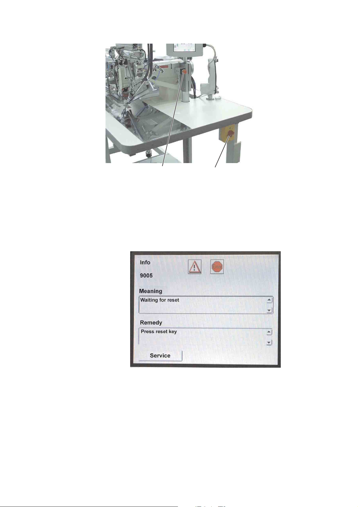
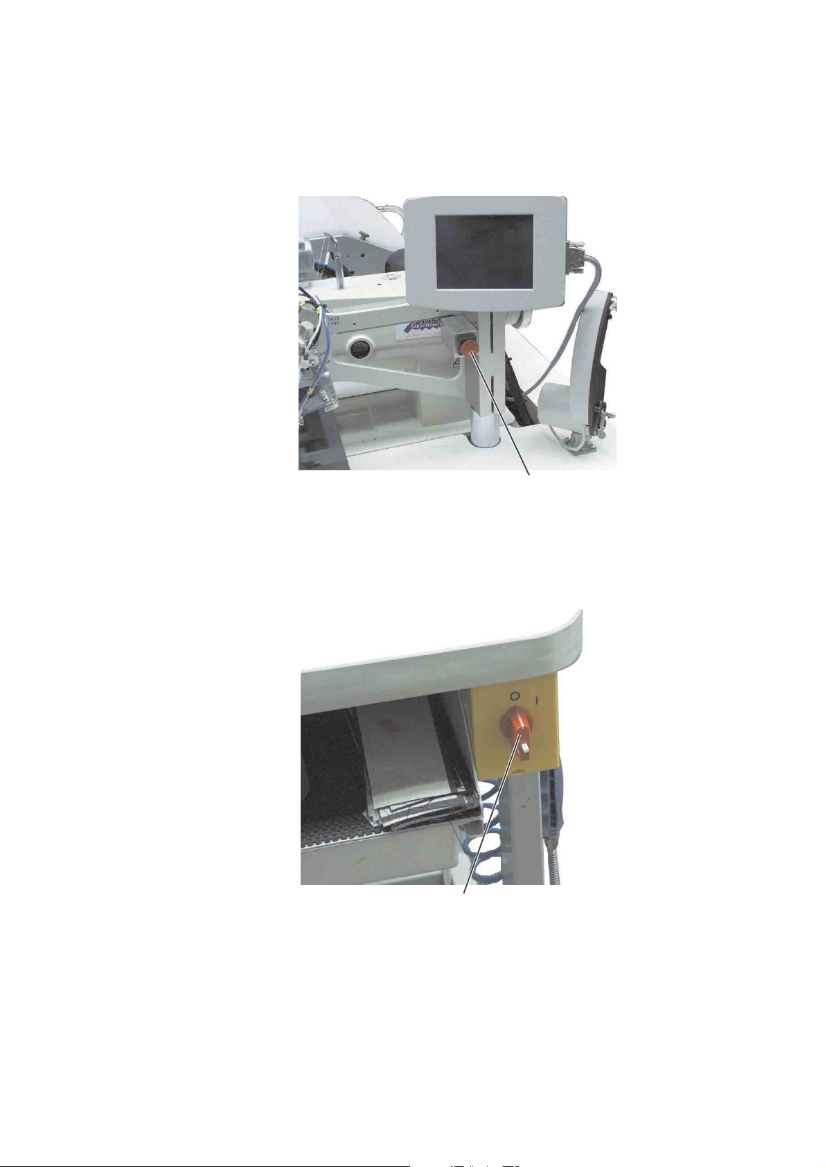
3.1 Switching on
–
switch the main switch 1 on (turn in clockwise direction).
The control loads the machine program.
The start screen appears in the display of the control panel and
indicates the following message:
–
Press the program stop switch 2.
If the transport clamps are not at the reference position, a
reference run is made.
14
Page 19
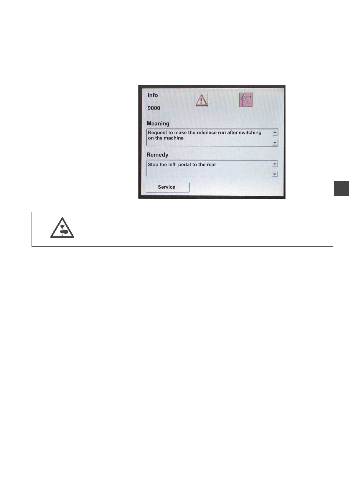
3.2 Reference position
Reference position
The reference position is necessary to reach a defined initial position.
When the sewing unit is switched on, the control checks whether the
transport carriage is in its rear end position.
If this is not the case, the display shows the following message:
1
Caution: Risk of injury !
Risk of bruises between folder and deposit table.
–
–
3.3 Starting the sewing process
–
–
–
The individual steps of the feeding process can be cancelled.
Press the program stop switch.
The reference run starts.
The transport carriage moves to its rear end position.
The display changes over to the main screen of the sewing unit.
Actuate the central foot switch.
By actuating the central foot switch repeatedly the different steps
of the feeding process are started one after the other.
The individual steps depend on the working method and on the
equipment of the sewing unit.
For feeding corrections:
Actuate the right foot switch or press the reset key.
The last step of the feeding process is cancelled.
The workpiece can be fed anew.
Step the central foot switch to the front.
The sewing process starts.
15
Page 20
3.4 Program stop
For an immediate switch-off of the sewing unit in case of operating
errors, needle breakage, material accumulation etc. the safety system
of the 100/68 will react as follows:
–
Press program stop 1.
The sewing process is stopped immediately.
3.5 Switching off
1
–
Switch the main switch 2 off (turn counter-clockwise).
16
2
Page 21

4. Working methods
The individual working methods for trousers and men’s jackets are
described on the following pages.
The description is structured as follows:
Feeding positions
This item indicates the feeding points for the different workpieces (e.g.
left and right parts).
Aligning the positioning aids
Here you will find a description how to adjust and align the positioning
aids (e.g. positioning marks, marking lamps, guides etc.).
Feeding and starting the sewing process
Here you will find a list of the individual feeding steps with
practice-oriented examples.
1
ATTENTION!
The steps of the feeding process are dependent on the equipment of
the respective sewing unit.
So the feeding steps described in the examples apply to sewing units
with the same equipment only.
Caution: Risk of injury!
Do not reach under the downholder, the transport clamp and the folder
during the feeding process.
17
Page 22

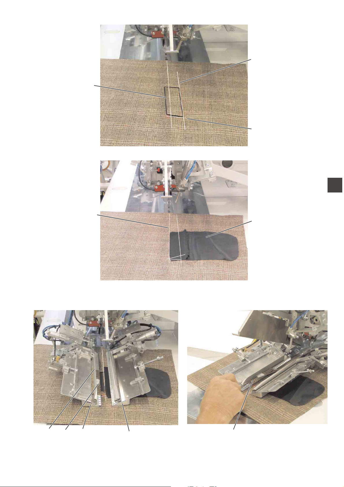
4.1 Working method “Production of trousers”
Possible processing variants
–
Front trousers pockets with pocket bag positioned underneath
–
Hind trousers pockets with or without flap, with pocket bag
positioned underneath
–
Hind trousers pockets with or without flap, with automatically fed
reinforcement strip
Feeding method
Example: Hind trousers without flap, with pocket bag positioned
underneath
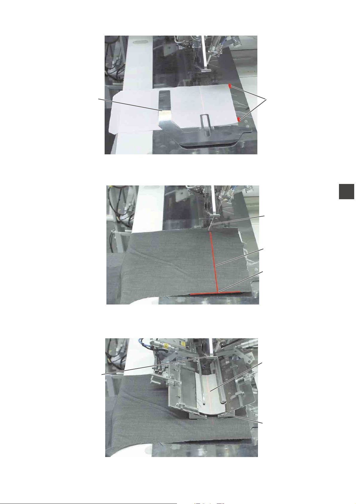
1st step:
–
Select the pocket program at the control panel
–
Push the pocket bag under the pocket bag clamp 1 and position it
at the markings 2.
For example adhesive strips fitted on the fabric sliding sheet may
serve as markings.
2nd step:
–
Position the hind trousers at the “central positioning point” 5 and
the marking 4.
–
Actuate the central foot switch.
The hind trousers is clamped by the fabric downholder 3.
–
Smooth out the clamped hind trousers in the dart area.
–
If the machine is additionally equipped with vacuum:
Actuate the left foot switch.
The vacuum is switched on.
3rd step:
–
Actuate the central pedal.
The transport clamps move to the front and lower on the
workpiece.
–
Position the piping strip 6 on the transport clamps flush with the
front edges 7.
The aligning of the various kinds of piping on the transport clamps
is described more exactly in the following.
See “Positioning of piping strips”.
–
Actuate the central pedal once again.
The folder 8 lowers.
–
Actuate the central foot switch once again.
The sewing process starts.
18
Page 23
1
2
1
3
4
5
6
8
7
19
Page 24

4.2 Working method “Breast welt pocket”
Processing patterned or plain-coloured fabrics
When processing plain-coloured fabrics it is not necessary to align
men’s jacket fronts and breast welts as per pattern.
Thus, plain-coloured fabrics can be processed more quickly.
- Align positioning aids
Feeding method
Example: Men’s jacket front with breast welt pocket, patterned fabric
1st step:
–
Select pocket program No. 7 at the control panel.
–
Position breast welt 1 on the jacket front as per the stripes.
–
Align the breast welt of the jacket front at the laser markings 2 and
3 (right and bias laser).
–
Step on the start pedal.
The vacuum is switched on.
The jacket front is sucked.
2nd step:
–
Remove breast welt 1.
–
Position pocket bag 4 at the left laser.
–
Step on the central pedal.
The fabric clamps move to the front.
The right clamp 6 clamps the jacket front.
The left clamp 7 remains pressureless.
3rd step:
–
Position breast welt 8 at the stop of the left fabric clamp (at the
front laser).
–
Fold back seam allowance 10 at the clamp and check the course of
the pattern in longitudinal direction.
Correct the course of the pattern by slightly pulling the jacket front
or by shifting the flap clamp 9.
–
Step on the central pedal.
Pressure is applied on the left fabric clamp 7.
–
Actuate the central pedal.
The folder lowers.
–
Actuate the central pedal once again.
The sewing process starts.
20
Page 25
2
1
3
1
4
5
987 6
10
21
Page 26
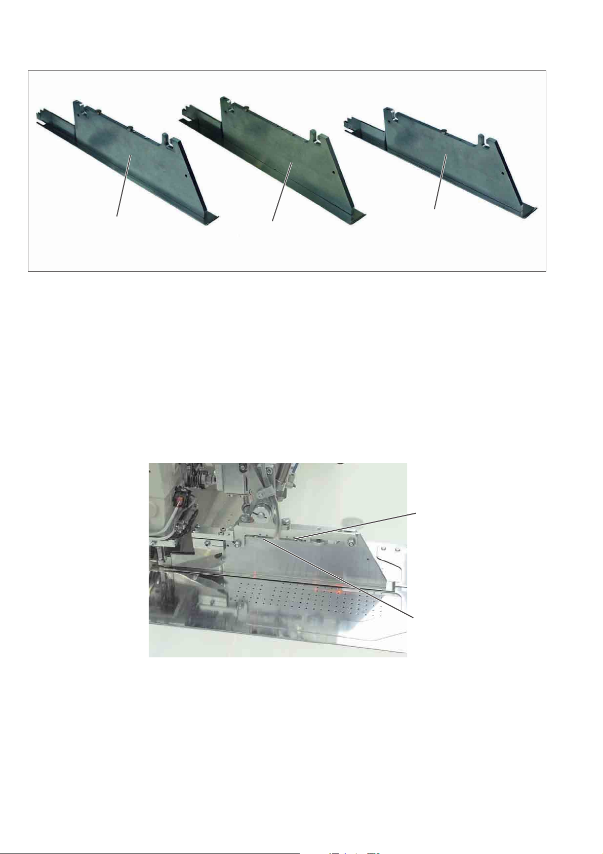
5. Quick clamp adjustment and folder monitoring
1
The lateral position of the transport clamps is influenced by the
solenoid switches SC103 and SC106.
According to the equipment the magnets are fitted on the folders in
different positions.
Depending on the selected folder the clamps are adjusted
automatically.
1 = Folder for double piping
2 = Folder for single piping, left
3 = Folder for single piping, right
2
3
SC103
22
SC106
Page 27
6. Function and operation of the optional equipment
This chapter describes the function and operation of the most
important
optional equipment.
6.1 Tape feeding unit with automatic trimming and tape monitor
The step motor- and length-controlled tape feed with automatic
trimming transports the reinforcement strip under the pocket opening
and cuts it off at the seam end (e.g. when sewing inside and outside
pockets of men’s jackets).
A sensor supervising the tape feed is integrated in the tape feeding
unit.
The whole sequence is realized within the machine time
so that there are no further feeding or secondary processing times.
If the tape is not pulled during the sewing process, e.g. in case of
accumulation or wrong threading, a message is produced by the
control.
1
Activating and switching the tape feed on
–
Activate the tape feed at the control panel in the menu item “Seam
functions”.
–
Tap the icon.
23
Page 28
21
54 3
24
98 7
11 10
5
3
Page 29

Inserting the reinforcement strip
–
Put roll 1 on the tape roll holder 2.
The full roll must rotate in the indicated arrow direction
(counter-clockwise) when unwinding.
–
Guide the reinforcement strip via guide 5.
–
Swivel the fabric sliding sheet 9 aside.
–
Press slide 7 backwards and lift off cover 8.
–
Insert the reinforcement strip in the feeding device according to the
sketch.
–
Swivel the fabric sliding sheet 9 back again.
–
Tap the key.
The reinforcement strip is cut off and moved to the initial position.
Function and operation
Before the next sewing cycle the reinforcement strip is fed forward a
little by the transport roller of the feeding device.
When sewing the pocket opening the reinforcement strip is seized and
sewn in according to the set sewing length.
The tape projection at the seam beginning and seam end can be set in
the menu item “Seam parameters” with the parameters 21 and 22 (see
programming instructions).
1
25
Page 30
6.2 Endless zipper device
Function
When the zipper halves are pulled by the transport clamps during the
sewing process, the feed rod 6 is pulled upwards by the zipper getting
shorter.
The feed rod switches the zipper feed on and the drive rollers 7 and 8
go on feeding the zipper until the switch rod drops and switches the
feed off again.
Thus it is made sure that there is always enough zipper material
available for sewing.
Activating and switching the zipper device on
–
Tap the key.
The zipper device is activated.
Caution: Risk of injury !
During the swivelling and cutting process.
26
Page 31

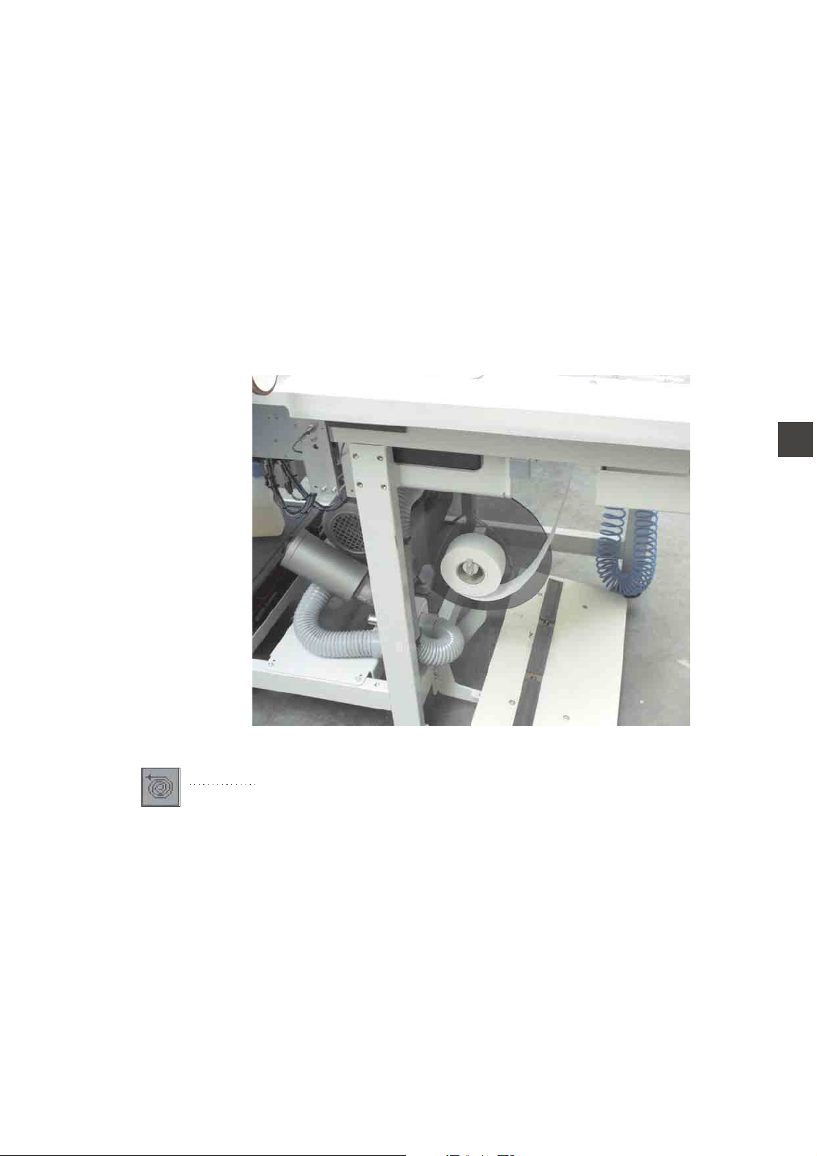
7. Maintenance
7.1 Cleaning
Caution: Risk of injury!
Switch the main switch off.
Carry out maintenance work only with the sewing unit switched off.
1
43 21
A clean sewing unit protects from malfunction!
Clean and check daily:
–
Clean the area around the hooks 2 and 3 with the compressed air
pistol.
–
When changing the bobbin always clean the lenses of the light
barriers 1 and 4
of the remaining thread monitor with a soft cloth.
–
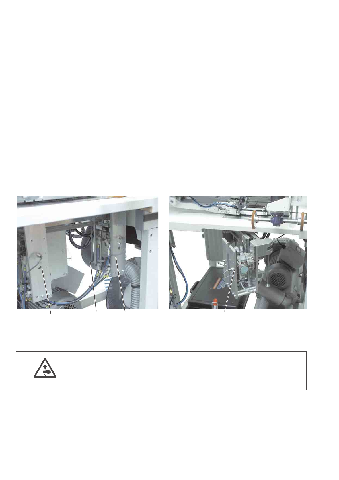
Cleaning of the filter ring 6 at the vacuum valve 5:
Blow out with compressed air pistol.
Clean and check daily:
–
Check the water level in the pressure regulator.
The water level must not reach the filter insert.
After screwing in the drain screw 2 blow the water
out of the water separator 1 under pressure.
The filter insert separates dirt and condensed water. After a certain
time of operation
wash the dirty filter tray and the filter insert with benzine and blow
them clean with the compressed air pistol.
21
65
ATTENTION!
Do not use any solvents for washing out the filter tray and the filter
insert!
They destroy the filter tray.
27
Page 32

7.2 Oil level control
For lubrication of the sewing machine head use exclusively the
lubricating oil
ESSO SP-NK 10.
SP-NK 10 can be bought from the sales office of Beisler GMBH
.
Checking the oil level in the oil reservoir 2 for the lubrication of
the machine head
–
The oil level in the oil reservoir 2 must not drop below the marking
“Min”.
–
If necessary, fill oil through the drill-hole 1 up to the upper marking.
21
28
Page 33

Index Page:
Part 2: Assembly instructions 100/68
1. Scope of delivery ............................................. 3
2. General notes ............................................... 3
3. Electrical connection ........................................... 4
3.1 Connecting the DACIII control panel ................................... 4
3.2 Making the mains connection ....................................... 4
4. Pneumatic connection .......................................... 5
5. Connection to the factory-own vacuum unit ............................ 6
6. Putting into operation .......................................... 7
222
Page 34

Page 35

1. Scope of delivery
–
Basic sewing unit for runstitching the openings of piped pockets,
flap pockets and welt pockets with rectangular and slanted pocket
corners, consisting of:
–
Step motors for material feed, length adjustment of the corner
trimming device
DC direct sewing drive
–
Twin needle lockstitch machine
–
DACIII control with control panel
–
Laser marking lamps
–
Sewing lamp (optional)
–
Compressed air maintenance unit with compressed air pistol
–
Thread reel holder
–
Material trays for additional parts to the right of the operator
and under the table top
–
Tools and small parts in the accessories
–
Feeding devices and sewing equipment according to the
working method
–
Optional equipment
2. General notes
ATTENTION !
The sewing unit must only be installed by trained specialist staff.
Any work on the electrical equipment of the sewing unit must
only be carried out by electricians or correspondingly instructed
persons.
The mains plug must be pulled out.
The enclosed operating instructions of the step motor manufacturer
have to be observed by all means.
3
Page 36

3. Electrical connection
ATTENTION!
Any work on the electrical equipment of the sewing unit must
only be carried out by electricians or correspondingly instructed
persons.
The mains plug must be pulled out.
3.1 Connecting the DACIII control panel
321
–
–
–
3.2 Making the mains connection
–
Put the control panel 1 in the holder 2 and screw it tight.
Push the plug 3 into the control panel cautiously.
Secure the plug with the two screws.
Connect the mains plug.
4
Page 37

4. Pneumatic connection
For the operation of the pneumatic components the sewing unit has to
be provided with anhydrous compressed air.
ATTENTION!
For a trouble-free function of the pneumatic control processes the
compressed air net has to be rated as follows:
Even in the moment of maximum air consumption the minimum
operating pressure must not drop below 6 bar.
In case of a too high air pressure decrease:
–
Increase the compressor output.
–
Increase the diameter of the compressed air supply line.
4321
Connecting the compressed air maintenance unit
–
Connect the connecting hose 4 to the shut-off valve 3 and to the
compressed air net.
Setting the operating pressure
–
The operating pressure amounts to 6 bar.
It can be read off at the manometer 2.
–
For setting the operating pressure pull up and turn the rotary
handle 1.
–
Turn in clockwise direction = increase the pressure
–
Turn counter-clockwise = reduce the pressure
2
ATTENTION !
No oil-bearing compressed air must be fed from the compressed air
net.
Behind the filter cleaned compressed air is withdrawn as blowing air
for cleaning machine parts and for blowing workpieces out.
Oil particles contained in the blowing air lead to malfunction and stains
on the workpieces.
5
Page 38

5. Connection to the factory-own vacuum unit
1
The suction unit facilitates the precise feeding and positioning of the
workpiece on the worktable 1.
–
Connect the hose of the factory-own vacuum unit to the connection
2.
Note:
If no factory-own vacuum unit is available, a vacuum unit has to be
ordered additionally.
2
6
Page 39

6. Putting into operation
After completion of the installation work a sewing test should be made.
–
Plug in the mains plug.
Caution: Risk of injury!
Switch the main switch off before threading the needle and hook
thread.
–
Threading the needle thread (see operating instructions).
–
Threading the hook thread (see operating instructions).
–
Switch the main switch on.
The main screen is displayed.
–
By actuating the central foot switch the different steps of the
feeding process are released one after the other and the sewing
process starts.
The individual steps depend on the working method and on the
equipment of the sewing unit.
ATTENTION !
Please take care that material is positioned under the transport clamps
at the sewing start.
Moving the transport carriage without material may damage the coating
of the transport clamps.
2
–
For the selection of the sewing program and for further settings of
the control unit see part 4: Programming instructions 100/68
–
For feeding and operating see part 1: Operating instructions 100/68
7
Page 40

Page 41

Index Page:
Part 3: Service instructions 100/68
1. General notes ................................................ 3
1.1 Raising/ Lowering the sewing machine head .............................. 4
2. Transport carriage ............................................. 6
2.1 Rear end position .............................................. 6
2.1.1 Position of the limit switch in the slotted hole .............................. 7
2.1.2 Distance between switching screw and limit switch .......................... 7
2.1.3 Stop guide for transport carriage ..................................... 7
2.2 Front end position .............................................. 8
2.2.1 Distance between switching screw and limit switch .......................... 9
2.2.2 Front end position of the transport carriage ............................... 9
2.2.3 Stop guide for the transport carriage ................................... 9
2.3 Toothed belt tension ............................................. 10
3. Transport clamps.............................................. 12
3.1 Transport clamp stroke ........................................... 12
3.2 Parallelism of the transport clamps .................................... 13
3.3 Distance between the transport clamps and the sole of the folder ................. 14
3.4 Parallelism of main clamp and sliding sheet .............................. 15
3.5 Folding slides................................................. 16
3.5.1 Adjusting travel and parallelism of the folding slides ......................... 16
3.5.2 Position of the folding slide when retracted ............................... 17
3.5.3 Adapting the folding slide ......................................... 18
3.6 Flap clamp .................................................. 19
3.6.1 Flap clamp position ............................................. 19
3.6.2 Opening stroke of the flap clamp ..................................... 20
3.7 Changing the rubber strips of the clamp ................................. 21
4. Folder ..................................................... 22
4.1 Changing the folder ............................................. 22
4.2 Position of the folder to the needles and to the centre knife ..................... 23
4.3 Lifting motion of the folder ......................................... 24
4.4 Guide plates at the folder ......................................... 26
3
5. Trimming and clamping device for the needle threads ...................... 28
5.1 Function .................................................... 28
5.2 Exchanging and adjusting knife and thread catcher .......................... 29
6. Centre knife ................................................. 30
6.1 Position of the centre knife ......................................... 30
6.2 Needle protection .............................................. 31
Page 42

Index Page:
7. Adjusting the bobbin thread catcher ................................. 32
7.1 Thread catcher ................................................ 32
8. Knives for corner incision
8.1 Presetting ................................................... 33
8.2 Belt tension .................................................. 34
8.3 Aligning the corner knife station as to the seams ........................... 35
8.4 Adjusting the slant of the corner incisions ................................ 37
8.5 Exchanging the corner knives ....................................... 38
9. Laser markings ............................................... 39
10. Photocells for flap scanning....................................... 40
11. Fabric sliding sheet and vacuum plate ................................ 41
11.1 Adjusting the height of the vacuum plate ................................ 41
12. Adjusting the optional equipment ................................... 42
12.1 Downholder .................................................. 42
12.2 Ejector roller ................................................. 43
12.3 Zipper scissors ................................................ 44
13. Hook lubrication .............................................. 48
14. Locator and tooth belt disc ....................................... 49
15. Maintenance................................................. 50
2
Page 43

1. General notes
The service instruction manual on hand describes the adjustment of
the sewing unit 100/68 in an appropriate sequence.
ATTENTION !
Some of the setting positions are interdependent.
Therefore it is absolutely necessary to do the adjustment following the
described order.
The operations described in the service instructions must only be
executed
by qualified staff and correspondingly instructed persons respectively!
Risk of breakage !
Before the sewing unit is put into operation again after having been
disassembled the necessary adjustments have to be carried out
according to the service instructions.
Before any adjusting operations of parts involved in the stitch
formation are made:
–
Insert a new needle without any damage.
Caution: Risk of injury !
Before repair, converting and maintenance work is done:
–
Switch the main switch off and disconnect the sewing unit from the
pneumatic
supply system.
Exception: Adjusting operations carried out with the help of test or
setting programs.
Adjusting operations and function tests when the sewing unit is
running
–
Carry out adjusting operations and function tests of the running
sewing unit
only under observation of all safety measures and with
utmost caution.
Adjusting operations in the needle zone
–
Parts which can lead to injuries have to be removed before
carrying out the adjusting operations.
Exception:
The parts are absolutely necessary for the adjusting operations.
3
3
Page 44

1.1 Raising/ lowering the sewing machine head
For maintenance and repair work the machine head can be raised.
For this purpose the transport carriage must be in its rear position.
Caution: Risk of injury!
Switch the main switch off.
Raise or lower the machine head only with the sewing unit switched
off.
1 2
43
4
Page 45

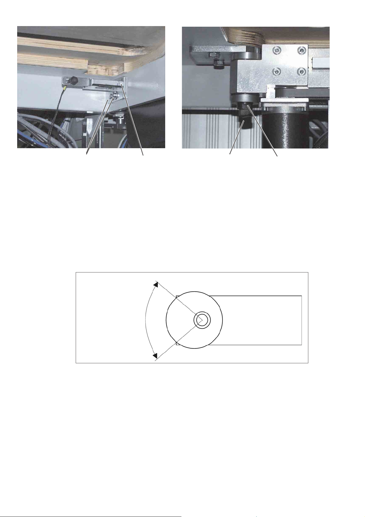
Raising the machine head
–
Swivel the folding station 1 aside by 90°.
–
Swivel the fabric sliding sheet 2 to the left.
–
Unscrew the fastening screw 6.
–
Loosen the screw at the locking lever 4 and raise the holder.
–
Tighten the screw.
–
Lift the machine head in the area of the head cover 3 and raise it
cautiously.
The area underneath the sewing machine head is accessible for
cleaning and adjusting now.
Caution: Risk of injury!
Do not reach into the cutout of the table top when the machine head is
raised.
Swinging the machine head back
–
Hold the machine head tight.
–
Lift the machine head cautiously until catch 5 releases.
–
Lower the machine head cautiously into the cutout of the table top.
–
Swivel the fabric sliding sheet back again and let it catch.
–
Loosen the screw at the locking lever 4.
–
Swivel the lever downwards.
–
Tighten the fastening screw 6 again.
–
Swivel the folding station back until it snaps in catch 5.
–
Tighten the screw at the locking lever 4.
3
452
6
5
Page 46

2. Transport carriage
2.1 Rear end position
432 1
Standard and checking
The switch 1 determines the rear end position of the transport carriage.
It must always be in the very rear of the slotted hole 2.
When the transport carriage is in its end position, there must be a
distance of 1 mm between the limit switch 1 and the switching screw 4.
When the transport carriage has gone back so far that the switching
screw 4 stands centrically under the switch 1, there must be a distance
of 2 mm between the transport carriage 5 and the stop 6.
Caution: Risk of injury!
Switch the main switch off.
Check and adjust the switch and the stop for the rear end position of
the transport carriage only with the sewing unit switched off.
76 5
8
9
6
Page 47

2.1.1 Position of the limit switch in the slotted hole
Checking
–
Unscrew the screws 8 and take off the covering cap 9.
–
Check the position of the limit switch 1 in the slotted hole 2.
Correction
–
Loosen the upper counternut at the limit switch 1.
–
Push the limit switch to the very rear of the slotted hole.
–
Tighten the upper counternut again.
Attention: Risk of breakage !
After operations on the limit switch always check the distance to the
switching screw 4.
2.1.2 Distance between switching screw and limit switch
Checking
–
Push the transport carriage 5 to the rear until the switching screw 4
is located under the limit switch 1.
–
Check the distance of 1 mm between limit switch 1 and switching
screw 4.
Correction
–
Loosen the counternut 3 at the switching screw 4.
–
Adjust the height of screw 4.
Distance between switching screw and limit switch=1mm.
–
Tighten the counternut 3.
3
2.1.3 Stop guide for the transport carriage
Checking
–
Push the transport carriage 5 to the rear until the surface of the
switching screw 4 is located centrically above the limit switch 1.
–
Check whether in this transport carriage position the distance
between the stop guide 6 and the transport carriage amounts to 2
mm.
Correction
–
Push the transport carriage to the rear until the surface of the
switching screw 4 is located centrically above the limit switch 1.
–
Loosen the counternut 7.
–
Approach the stop guide 6 to the transport carriage by 2 mm.
–
Tighten the counternut 7.
7
Page 48

2.2 Front end position
1 43 12
Standard and checking
The switch 1 determines the front end position of the transport
carriage.
It must be set in such a way that there is a distance of 325 mm
between the needles and the fronts of the transport clamps when they
have moved to the front.
When the transport carriage is in its front end position, there must be a
distance of 1 mm between the limit switch 1 and the switching screw 4.
When the transport carriage has moved forward so far that the
switching screw 4 stands centrically under the switch 1, there must be
a distance of 2 mm between the transport carriage 7 and the stop 6.
325 mm
Caution: Risk of injury!
Switch the main switch off.
Check and adjust the switch and the stop for the front end position of
the transport carriage only with the sewing unit switched off.
76 5
8
Page 49

2.2.1 Distance between switching screw and limit switch
Checking
–
Push the transport carriage 7 to the front until the switching screw
4 is located under the limit switch 1.
–
Check the distance of 1 mm between limit switch 1 and switching
screw 4.
Correction
–
Loosen the counternut 3 at the switching screw 4.
–
Adjust the height of screw 4.
Distance between switching screw and limit switch=1mm.
–
Tighten the counternut 3.
2.2.2 Front end position of the transport carriage
–
Push the transport carriage 7 to the front until the switching screw
4 is located under the limit switch 1.
–
Measure the distance between the needles and the fronts of the
transport clamp.
This must amount to 325 mm.
–
Adjust the limit switch 1 in the slotted hole accordingly.
2.2.3 Stop guide for the transport carriage
Checking
–
Push the transport carriage 7 to the front until the surface of the
switching screw 4 is located centrically above the limit switch 1.
–
Check whether in this transport carriage position the distance
between the stop guide 6 and the transport carriage amounts to 2
mm.
Correction
–
Push the transport carriage to the front until the surface of the
switching screw 4 is located centrically above the limit switch 1.
–
Loosen the counternut 5.
–
Approach the stop guide 6 to the transport carriage by 2 mm.
–
Tighten the counternut 5.
3
9
Page 50

2.3 Toothed belt tension
12
Caution: Risk of injury!
Switch the main switch off.
Check and adjust the toothed belt tension only with the sewing unit
switched off.
Standard and checking
Over the tightening length S= 300 mm the toothed belt must bend
under the test load FV = 34 N.
Consequences of a too high toothed belt tension
–
Reduced durability
–
Noisy running
Consequences of a too low toothed belt tension
–
No faultless mesh between belt teeth and disc toothing
–
The teeth may skip over under load
–
Non-uniform stitch lengths
–
Loss of steps possible
10
–
Unscrew the screws 1 and take off the covering cap 2.
–
Place the test load in the middle of the toothed belt (e.g. with the
help of a spring balance).
The tension of the toothed belt is correct if the upper belt half just
touches the lower one.
Page 51

43
Correction
–
Loosen the counternut 3.
–
Adjust the toothed belt tension with the Allen screw 4.
–
Tighten the counternut 3.
3
11
Page 52

3. Transport clamps
3.1 Transport clamp stroke
32 1
Caution: Risk of injury!
Switch the main switch off.
Check and adjust the transport clamp stroke only with the sewing unit
switched off.
Standard and checking
When the flap clamps 3 are closed, the raised transport clamps 1 and 2
must pass the machine arm without hitting it.
The distance between the front edges of the raised transport clamps
and the fabric sliding sheet should amount to 28 mm on the left and on
the right.
–
Push the transport carriage under the machine arm.
–
Check the stroke of the two transport clamps.
Correction
–
Loosen screw 4.
–
Adjust the height of the transport clamps.
–
Tighten the screws 4.
4
12
Page 53

3.2 Parallelism of the transport clamps
321 654
Caution: Risk of injury!
Switch the main switch off.
Check and adjust the parallelism of the transport clamps only with the
sewing unit switched off.
standard and checking
The transport clamps 1 and 2 should run parallel to the edge of the
sliding sheet 3.
–
Push the transport carriage to the front.
–
Check the distance of the transport clamps to the edge of the
sliding sheet.
Correction
–
Loosen the screws 4 and 6.
–
Adjust the transport clamps with the screws 5 so that they are in
parallel position to the edge of the sliding sheet.
–
Tighten the screws 4 and 6.
3
13
Page 54

3.3 Distance between the transport clamps and the sole of the folder
21
Standard and checking
There must be a certain distance between the outer edges 1 of the
folder sole and the inner edges 2 of the transport clamps. When
processing medium-weight materials the distance should amount to
approx. 1.0 to 1.5 mm.
The distance is necessary to guarantee uniform piping strips on both
sides as well as an unhindered material feed.
Caution: Risk of injury!
Switch the main switch off.
Check and adjust the transport clamps only with the sewing unit
switched off.
Attention: Risk of breakage !
Before adjusting the folder has to be correctly aligned (see chapter
“4.2 Position of the folder as to the needles and the centre knife”).
–
Push the transport carriage to the front.
–
Let the compressed air off.
–
Lower the folder.
–
Check the distance between folder sole and transport clamps.
54 3
14
Correction
–
Adjust the clamping arm 4 with the knurled nuts 3 and 5.
Page 55

3.4 Parallelism of main clamp and sliding sheet
1
Caution: Danger of injury!
Switch the main switch off.
Check and adjust the transport clamps only with the sewing unit
switched off.
Standard and checking
The main clamp 1 must be in parallel position to the sliding sheet over
its whole length.
–
Move the clamp to the feeding position.
–
Place thin fabric under the clamping arms.
–
Close the main clamp.
–
Pull the fabric out to the side and check for equal distance.
Correction
–
Loosen the counternuts 2.
–
Adjust the pressure with the Allen screws 3.
–
Tighten the counternuts 2 again.
32
3
15
Page 56

3.5 Folding slides
3.5.1 Adjusting travel and parallelism of the folding slides
21
Caution: Risk of injury!
Switch the main switch off.
Check and adjust the folding slides only with the sewing unit
switched off.
Standard and checking
According to the needle distance the folding slides 1 and 2 have to be
shifted by the following values when extending and retracting.
Needle distance 10 mm = approx. 3.5 mm
·
Needle distance 12 mm = approx. 4.5 mm
·
Needle distance more than 14 mm = max. stroke
·
–
Check the distance of the folding slides.
Correction
–
Loosen the screws 3.
–
Adjust the cylinder 4 correspondingly.
–
Align the folding slides in parallel position.
–
Tighten the screws 3.
–
Check distance and parallelism of the folding slides once again.
43
16
Page 57

3.5.2 Position of the folding slide when retracted
21
Caution: Risk of injury!
Switch the main switch off.
Check and adjust the folding slide only with the sewing unit
switched off.
Standard and checking
When retracted the folding slide 2 must be located
0.5 mm behind the edge of main clamp 1.
–
Check the position of the folding slide.
Correction
–
Loosen counternut 3.
–
Adjust the screw 4 in such a way that the folding slide 2 is located
0.5 mm behind the edge of main clamp 1.
–
Tighten the screws 4.
43
3
17
Page 58

3.5.3 Adapting the folding slide
321
Caution: Risk of injury!
Switch the main switch off.
Check and adjust the folding slide only with the sewing unit
switched off.
Standard and checking
The rotation of the folding slide 1 must be guaranteed so that it can
automatically adapt itself to the thickness of the material to be
processed.
The folding slide 1 must have no axial backlash.
–
Check the folding slide 1 in the holder for lateral clearance.
Correction
–
Loosen the counternut 2.
–
Adjust the folding slide with Allen screw 3 in such a way that there
is neither clearance nor rough rotation.
–
Tighten the counternut 2.
18
Page 59

3.6 Flap clamp
3.6.1 Flap clamp position
5mm
21 43
Caution: Danger of injury!
Switch the main switch off.
Check and adjust the flap clamp only with the sewing unit switched off.
Standard and checking
The flap clamps 2 must have a distance of 5 mm parallel to the inside
of the main clamp 1.
–
Close the flap clamp manually.
–
Check the distance between flap clamp 2 and the inside of main
clamp 1.
Correction
–
Loosen the screws 4.
–
Shift the flap clamp holder 3 correspondingly.
–
Tighten the screws 4.
3
19
Page 60

3.6.2 Opening stroke of the flap clamp
32 1
Caution: Risk of injury!
Switch the main switch off.
Check and adjust the flap clamp with utmost caution when the sewing
unit is switched on.
Standard and checking
The opening stroke of the flap clamp 3 must be adjusted in such a way
that the whole length of the flap clamp is pressed against the main
clamp when the flap clamp cylinder 2 is extended.
–
Switch the sewing unit on.
–
Close the flap clamp.
–
Check whether the flap clamp is pressed against the main clamp
over its whole length.
Correction
–
Loosen the screws 1.
–
Shift the cylinder 2 correspondingly.
–
Tighten the screws 1.
20
Page 61

3.7 Changing the rubber strips of the clamp
52 1 34 3
Caution: Risk of injury!
Switch the main switch off.
Dismount and mount the main clamp only with the sewing unit switched
off.
Standard and checking
There are sponge rubber strips under the main clamps. In case of
material processing problems the rubber strips should be checked and
replaced, if required.
–
Check the rubber strips.
Correction
–
Unscrew the screws 5.
–
Take the clamp off.
–
Unscrew the screws 3.
–
Exchange the rubber strips 4 and tighten with the screws 3.
–
Mount the clamp again.
Note
When processing thick fabrics it is of advantage to equip the clamp
with a thicker rubber strip or to fit an elevation.
3
21
Page 62

4. Folder
4.1 Changing the folder
21
Caution: Risk of injury!
Switch the main switch off.
Dismount and mount the folder only with the sewing unit switched off.
Dismounting the folder
–
Loosen the screw 4.
–
Pull the folder 3 to the front out of the drill-holes 1 and 2.
–
Cautiously remove the folder in downward direction.
Inserting the folder
–
Insert the folder 3 in the holder with its fastening drill-holes 1 and 2
on top and push it to the very back.
–
Tighten the screw 4.
43
22
Page 63

4.2 Position of the folder to the needles and to the centre knife
321
Caution: Risk of injury!
Switch the main switch off.
Align the folder as to the needles and to the centre knife only with the
sewing unit switched off.
Standard and checking
If the folder is fitted correctly, the following conditions must be fulfilled:
When the folder is lowered, the needles 4 must penetrate the needle
holes 5 of the folder sole 1 unhindered and without being pushed
aside.
When the centre knife 3 penetrates the centre knife protection 2, the
hind edge of the knife must be flush with the knife protection.
–
Make the machine pressureless.
–
Press the folder down completely by hand.
–
Check the position of the folder sole to the needles and to the
centre knife.
Correction
–
Make the machine pressureless.
–
Press the folder 2 down manually.
–
Loosen the screws 6 slightly.
–
Align the folder 2 as to the centre knife and the needles.
–
26
Tighten the screws 6.
54
3
Attention: Risk of breakage!
After adjusting the distance between the transport clamps and the
folder sole has to be checked (see chapter “3.3 Distance between the
transport clamps and the sole of the folder”)
23
Page 64

4.3 Lifting motion of the folder
21
Caution: Danger of injury!
Switch the main switch off.
Adjust the lifting motion of the folder only with the sewing unit switched
off.
Standard and checking
The distance between sliding sheet 2 and folder sole 1 has to be
adapted to the material to be processed.
If the folder is adjusted too deep, the material is blocked.
If the folder is adjusted too high, the folding slides cannot fold the
material.
When the folder is lowered
In this position there must be a clearance of 0.3 - 0.5 mm between the
guide roller 4 and the lowest point of the guide groove 3.
When the folder is raised
When the folder is raised, there must still be some clearance between
the guide roller 4 and the highest point of the guide groove 3.
–
Press the folder down to the fabric sliding sheet by hand.
–
For this purpose turn the stop 6 back, if required.
–
Check the air gap between guide groove 3 and guide roller 4.
–
65
Lift the folder up to the upper stop 5.
–
Check the air gap between guide groove 3 and guide roller 7.
43
24
Correction
–
Adjust the rod end 5 on the piston rod of the cylinder.
If - with the folder lowered - the guide roller 4 hits the guide groove and
the folder is not lowered as far as required, the guide groove has to be
readjusted (see next page).
Page 65

98
Caution: Risk of injury!
switch the main switch off.
Adjust the guide groove for the folder only with the sewing unit
switched off.
–
Loosen the screws 8 and 9.
–
Shift the cam segment 6 in the slotted holes.
–
Tighten the screws 8 and 9.
12
67
3
10
11
Stop screw with spring
Standard and checking
The stop screw 10 has to be adjusted in such a way that - with the
folder lowered - the distance between the folder sole and the sliding
sheet amounts to approx.1-2mm(dependent on the fabric).
The integrated spring presses the folder back so that the piping strip is
safely seized when sewing (during the last section of the backward
movement the cylinder is pressureless).
–
Turn the stop screw 10 in such a way that - if the folder is lowered the stop screw 10 abuts on the stop 11 (make sure that it snaps in).
–
Adjust the spring pressure with screw 12 in the stop screw 10 so
that the folder is pressed back.
25
Page 66

4.4 Guide plates at the folder
321
Caution: Risk of injury!
Switch the main switch off.
Adjust the guide plates only with the sewing unit switched off.
Standard and checking
The lateral distance between the guide plates 2 and the needles
should be as small as possible. However, the guide plates must not
abut on the needles or the needle holders 3 because this may lead to a
high noise level, damage to the guide plates and the needle head as
well as to thread breakage.
The distance between the sole top 1 and the bottom of the guide plate
2 should not exceed 0.5 mm.
Only when processing especially thick materials the distance has to be
increased.
–
Lower the folder.
–
Check the position of the guide plates as to the needles.
Correction
Aligning the guide plates
–
Cautiously align the guide plates by means of a flat pliers.
54
26
Adjusting the height of the guide plates
–
Loosen the counternuts 4 and 5.
–
Adjust the distance of the guide plates 2 with the Allen screws.
–
Tighten the counternuts 4 and 5.
Page 67

Pressure of the guide plates
76
The spring pressure has to be adjusted in such a way that both plates
are always pressed down safely.
If the pressure is too low, the needles may break during the initial
bartack.
If the pressure is too high, the flap or the additional parts are pushed
back at the seam beginning.
If the pressure is too low, the material may be lifted, the stitch
formation may be incorrect or the needles may break.
3
Adjusting the pressure of the guide plates
–
Loosen the counternut 7.
–
Adjust the pressure on the guide plate with the Allen screw 6.
–
Tighten the counternut 7.
27
Page 68

5. Trimming and clamping device for the needle threads
5.1 Function
21
Caution: Risk of injury!
Switch the main switch off.
Check knife and thread catcher only with the sewing unit switched off.
Function
–
–
–
–
Function check
–
–
–
–
–
43
The cylinder 2 is switched on after the seam end and during the
feed to the corner knives.
The thread catcher 3 lowers and takes the needle threads up.
After a preset time the thread catcher shoots up.
The needle threads are clamped at the clamping piece 1 and cut off
by knife 4.
After the first stitches of the next seam the clamped needle threads
are released.
By means of the springy clamping sheet 1 the thread catcher 3
abuts flat on the knife 4. Thus, the knife is automatically in parallel
position.
Call up the adjustment and test program “Selecting the output
elements” (see programming instructions chapter 5.6.1 Multitest).
Select the output element “Y1”.
Pull the needle threads to the back.
Switch the output element on and off by pressing the function key
“OK”.
Check whether the threads are accurately cut and clamped.
28
Page 69

5.2 Exchanging and adjusting knife and thread catcher
2,5-3mm
765438
Caution: Risk of injury!
Switch the main switch off.
Exchange knife and thread catcher only with the sewing unit switched
off.
3109
Exchanging knife and thread catcher
–
Screw off the complete thread catcher from the machine head.
–
Unscrew the screws 6.
–
Remove knife 5.
–
Unscrew screw 7 and remove knife protection 8.
–
Unscrew screw 4 (on the rear).
–
Take off the needle thread catcher 3.
–
Insert new thread catcher and tighten with screw 4.
–
Put on new knife 5 and tighten with screws 6.
Set the dimensions 2.5-3mmand1.5mm.
–
Make a cutting and clamping test. Adjust the clamping pressure by
means of screw 10, if required.
1mm
3
5
29
Page 70

6. Centre knife
6.1 Position of the centre knife
432 1
Caution: Danger of injury!
Switch the main switch off.
Disconnect the sewing unit from the pneumatic system.
Adjust the centre knife only with the sewing unit switched off.
Standard and checking
In the bottom dead centre the front edge of centre knife 2 must stand
approx. 1 mm under the cutting edge of the stationary knife in the
throat plate.
The centre knife 2 should be in parallel position to the counterknife in
the throat plate.
The center knife 2 must abut on the stationary knife in the throat plate
with a slight pressure.
–
Move the centre knife 2 to the bottom dead centre.
–
Check whether the edge of knife 2 is max. 1 mm under the
stationary knife.
Correction
Adjusting the height of the knife
–
Move the centre knife to the bottom dead centre.
–
Loosen screws 1.
–
Adjust the height of centre knife 2.
–
Tighten screws 1.
30
Adjusting the knife holder
–
Move the centre knife to the bottom dead centre.
–
Loosen screw 4.
–
Turn the knife block 3 in such a way that the centre knife is in
parallel position to the knife in the throat plate.
–
Tighten screw 4.
Page 71

62 5
Contact pressure
–
Loosen the two screws 5.
–
Place the knife holder 6 with the centre knife 2 to the left against
the stationary knife in the throat plate.
The centre knife must abut with slight pressure.
–
Tighten the screws 5.
87 2
6.2 Needle protection
–
Make a cutting test.
Attention !
Disturbances of the machine cycle may occur.
If the centre knife abuts too close on the counterknife edge, the spring
cannot pull it to the initial position any more after the sewing process.
Furthermore, the knife will quickly get blunt which may result in
inaccurate cutting, different seam lengths, inexact corner incision and
fullness within the seam.
The needle protection 7 is fixed on the holder of the needle thread
catcher.
It should be located 1 mm deeper than the point of the centre knife 2
and
1.0 - 1.5 mm from its back.
–
Loosen the screws 8.
–
Adjust the needle protection 7 in such a way that it is located 1 mm
deeper than the point of the centre knife und 1.0 - 1.5 mm from its
back.
–
Tighten the screws 8.
3
31
Page 72

7. Adjusting the bobbin thread catcher
7.1 Thread catcher
1
27,2 mm
32 1
Caution: Risk of injury!
Switch the main switch off.
Adjust the bobbin thread catcher only with the sewing unit switched off.
Standard and checking
The thread catchers are correctly adjusted if the thread catcher point 2
in idle state has a distance of 27.2 mm to the edge 1 and a distance of
0.1 mm to the nose of bobbin case 4.
–
–
–
0,1 mm
4
2
Swivel the thread catcher out.
Check whether the point 2 has a distance of 27.2 mm to the edge
1.
Check whether there is a distance of 0.1 mm between the thread
catcher and the nose of the bobbin case 4.
32
Correction
–
Loosen the screws 3.
–
Adjust the thread catcher 2 correspondingly.
–
Tighten the screws 3.
6
Counterknife
–
5
Regrind or exchange the blunt counterknives 5 and 6.
Page 73

8. Knives for corner incision
Caution: Danger of injury!
Do not reach into the area of the corner knives.
The corner knives shooting up can cause severe cuts.
Carry out adjusting operations with utmost caution when the sewing
unit is running.
8.1 Presetting
1
2
6
5
3
3
7
4
In order to be able to precisely adjust the position of the corner knives
1 all four corner knives are brought to a basic position at first.
–
Loosen screw 6.
–
Turn the corner knife holder 2 in such a way that the face side 3 is
in a line with the face side 4 of the knife support 5.
–
Tighten screw 6.
–
Adjust the other three knife holders as described.
–
Adjust the grub screw 7 in such a way that the edges of the
opposite knives have a distance of 0.1 to 0.3 mm.
–
Grub screw 7 to the right: knives closer together.
–
Grub screw 7 to the left: knives wider apart.
–
Adjust the other knives likewise.
33
Page 74

8.2 Belt tension
1
Standard and checking
Over half the tightening length S = 185 mm the toothed belt 1 must
bend under the test load FV = 50 N so that the loaded belt just touches
the other belt.
Consequences of a too high toothed belt tension
–
Reduced durability
–
Noisy running
Consequences of a too low toothed belt tension
–
No faultless mesh between belt teeth and disc toothing
–
The teeth may skip over under load
–
Non-uniform corner stitches
–
Check the belt tension with a spring balance.
Correction
–
Loosen the counternut 3.
–
Adjust the belt tension with the eccentric screw 2.
–
Tighten the counternut 3.
32
34
Page 75

8.3 Aligning the corner knife station as to the seams
Caution: Risk of injury!
Switch the main switch off.
Adjust the corner knife station only with the sewing unit switched off.
Standard checking
The corner incisions must be symmetrical to the seams.
–
Set the maximum sewing length at the control.
–
Iron a piece of interfacing on a workpiece.
Thus the corner incisions are better visible.
–
Make a test seam.
–
Check seam and cutting pattern.
Correction of the corner incision at the seam end
–
Swivel the corner knife station 1 out completely.
3
1
35
Page 76
32
–
Loosen the screws 3 slightly.
–
Shift the holder 2 correspondingly.
–
Tighten the screws 3.
–
Swivel the corner knife station back again.
Correction of the corner incision at the seam beginning
–
Loosen the screw 5 slightly.
–
Adjust the corner knife station with the hexagon screw 4.
ATTENTION !
Observe the position of the eccentric.
Setting range
54
36
–
Tighten the screw 5.
–
Make a test seam.
–
Check seam and cutting pattern.
Page 77

8.4 Adjusting the slant of the corner incisions
Caution: Risk of injury!
Switch the main switch off.
Adjust the corner knives only with the sewing unit switched off.
Standard and checking
The incisions of the corner knives should be as close to the seam as
possible (approx. 1 mm), but must not cut it.
–
Set the maximum sewing length at the control.
–
Sew a test seam.
It is advisable to iron a piece of interfacing on the workpiece
before. Thus the corner incisions are better visible.
–
Check seam and cutting pattern.
3
6
2
–
Loosen screw 6.
–
Adjust the corner knife holder 2 correspondingly.
–
Tighten screw 6.
–
Adjust the other three knife holders according to the seam pattern.
37
Page 78

8.5 Exchanging the corner knives
3
2
Caution: Risk of injury!
Switch the main switch off.
Exchange the corner knife station only with the sewing unit switched
off.
Risk of cuts.
Do not reach into the sharp edges of the corner knives.
Blunt knives are to be exchanged against a set of knives included in
the accessories.
–
Swivel the corner knife station out.
–
Loosen screw 2.
–
Remove the old corner knife.
–
Insert a new corner knife in the knife holder 3.
–
Tighten screw 2.
–
Swivel the corner knife station in again.
38
Page 79

9. Laser markings
According to the equipment the 100-68 is provided with 6 lasers for
marking the positioning points.
The following values are basic values:
2
3
4
5
6
1
1 : Needles
2 : Marking of the front positioning point
3 : Auxiliary positioning line for the production of men’s jackets
4 : Marking of the central positioning point
5 : Auxiliary positioning line for the production of men’s jackets
6 : Marking of the rear positioning point
3
39
Page 80

10. Photocells for flap scanning
43 2 1
Caution: Risk of injury!
Switch the main switch off.
Adjust the reflected light barriers only with the sewing unit
switched off.
Standard and checking
The light spots 2 and 3 of the photocells 1 and 4 must shine on the
reflected foils of the main clamp.
The light spots must hit the reflected foil approx. 1.5-2mmfrom the
outside edge.
–
Check whether the light beam of the photocells shines on the
reflected foil.
Correction
–
Loosen the screws at the photocell.
–
Adjust the photocell.
–
Tighten the screws at the photocell.
7654
40
Correction of left light barrier for breast welt pocket
As far as sewing units for breast welt pockets are concerned, the left
light barrier 4 is automatically set to the correct position by the cylinder
6 when selecting a breast welt program.
–
Select the breast welt program.
–
Position the breast welt.
–
Loosen screw 5.
–
Adjust the light barrier with the eccentric 7 to match the breast
welt.
–
Tighten screw 5.
Page 81

11. Fabric sliding sheet and vacuum plate
11.1 Adjusting the height of the vacuum plate
1
Standard and checking
The vacuum plate should be on one level with the table top.
–
Lift the fabric sliding sheets 1 at the front and swivel them to the
left.
–
Check the height of the vacuum plate as to the table top.
Caution: Risk of injury!
Switch the main switch off.
Adjust the vacuum plate only with the sewing unit switched off.
The vacuum plate is connected with the table top support by four core
pins 2.
–
Turn the core pins 2.
In clockwise direction = vacuum plate higher
Counter-clockwise = vacuum plate lower
–
Readjust the support screws 3.
32
3
41
Page 82

12. Adjusting the optional equipment
12.1 Downholder
6
43 2 1
With the downholder the fullness in the pocket opening area caused by
darts is smoothened and safely held.
Caution: Risk of injury !
Switch the main switch off.
Check and adjust the downholder only with the main switch
switched off.
Standard
The downholder 3 should be aligned in such a way that it lowers
exactly on the drill-hole 5 in the sliding sheet.
It must be aligned in such a way that it is not hit by the opened clamps.
Adjusting the downholder
–
Loosen the screws 2 at the holder 1.
–
Adjust the height of the downholder 3.
When the pedal is actuated, the extended piston rod should just
touch the hole in the fabric sliding sheet.
–
Align the downholder 3 to the back (in machine head direction).
The piston rod should hold the hind trousers part clamped.
–
Tighten the screws 2 on the holder 1.
–
Regulate the lowering speed of the downholder 3 with the throttle
valves 4 and 5.
The lowering motion should be rapid, but not abrupt.
53
42
Page 83

12.2 Ejector roller
321
In the production of trousers the ejector roller is used separately.
In the production of men’s jackets it is used in combination with the
throw-over stacker.
The transport rollers 1 and 2 convey the workpiece to the opening of
the throw-over stacker so that it is safely stacked.
Caution: Risk of injury!
Switch the main switch off.
Adjust the ejector roller only with the main switch switched off.
The transport rollers must be aligned in parallel position to the table
top and the centre of the pocket opening.
Adjusting the height of the transport rollers
In lowered position both transport rollers 1 and 2 should equally rest on
the table top.
–
Loosen screw 4.
–
Shift the operating lever 5 in such a way that both rollers rest on
the table top with slight pressure.
–
Tighten screw 4.
54
3
Adjusting the throttle valves
–
Adjust the lowering and lifting speed at the throttle valves 1 and 2.
The lowering speed should be rapid, but not abrupt.
Throttle valve 1 = lowering speed
–
Throttle valve 2 = lifting speed
43
Page 84

12.3 Zipper scissors
12.3.1 Adjusting the scissors
543 2 1
The zipper scissors 2 is used for cutting endless zippers to length.
Cylinder 6 swivels the scissors down; cylinder 5 actuates the scissors.
Caution: Risk of injury !
Switch the main switch off.
Check and adjust the zipper scissors only with the main switch
switched off.
Standard
The scissors 2 must swivel in so far that both zipper parts 1 are cut.
The farther the zipper parts are within the scissors, the lower is the
wear and tear of the scissors parts.
When swivelled in the scissors must not touch the needles.
Adjusting the scissors
–
Loosen counternut 7.
–
Press the scissors 2 down manually and adjust it with the piston
rod 6 in such a way that the scissors is in parallel position to the
support sheet.
–
Tighten counternut 7.
–
Loosen screws 4.
–
Adjust the distance between scissors and needles.
–
Tighten screws 4.
–
Adjust the piston rod 3 of cylinder 4 in such a way that the closed
halves of the scissors overlap slightly when the cylinder is
extended.
76
44
Page 85

12.3.2 Adjusting the carriers for zipper parts
1
The carriers 1 support the feed of the two zipper parts.
Caution: Risk of injury !
Switch the main switch off.
Check and adjust the carriers only with the main switch switched off.
Standard
During the feed the two carriers 1 should rest on the zipper parts
centrally and with equal pressure.
The buffers 5 of the carriers have to be extended by the cylinders 3
and 4 so far that the guide rail 2 is transported without slippage.
5432
3
45
Page 86

321
54
76
10 9
87
46
Page 87

Parallelism of the carriers 1 to the fabric sliding sheet
–
Loosen screw 3.
–
Turn holder 2 in such a way that both carriers 1 have the same
distance to the fabric sliding sheet.
Height of the carriers 1 as to the fabric sliding sheet
–
Loosen counternut 5.
–
Turn the piston rod in such a way that there is a distance of approx.
0.5 mm between the lowered carriers and the fabric sliding sheet.
Adapting the carriers 1 to the seam distance
The carriers are adapted to the seam distance by bending.
–
Align the carriers cautiously by lateral bending.
Front adjustment of the carriers
The carriers are positioned correctly if there is a distance of approx. 2
mm between the rotary disc 6 of the scissors and the guide rail 7 in the
front end position of rail 7.
–
Push the guide rail 7 right to the front.
–
Loosen screws 8.
–
Adjust the guide rail in such a way that there is a distance of
approx. 2 mm between the rotary disc 6 of the scissors and the
guide rail 7.
–
Tighten screws 8.
Carriers of the guide rail
The buffers 10 of the carriers have to be extended by the cylinders 9
so far that the guide rail is transported without slippage.
The distance between the buffers 10 of the carriers should be narrower
than the thickness of the guide rail.
–
Unscrew cylinder 9.
–
Adjust the piston rods of the cylinders correspondingly.
–
Screw cylinder 9 on again.
3
47
Page 88

13. Hook lubrication
21
Standard
The necessary oil quantity has been adjusted by the manufacturer with
the screws 1 and 2. It should be reduced or increased in special cases
only.
–
Adjust the screws 1 and 2.
–
Screw the screws in: less oil.
–
Screw the screws out: more oil.
Attention !
Do not screw in the screws too deeply! The oil wick may be damaged.
48
Page 89

14. Locator and tooth belt disc
42 1
31
87 65
Caution: Risk of injury !
Switch the main switch off.
Adjust the locator only with the sewing unit switched off.
Standard
To guarantee a precise positioning the toothed disc 2 has to be
positioned in such a way that the wedge 1 is not in the hatched area 3
when the machine is positioned.
After positioning the thread lever should be in the top dead centre.
Adjusting the toothed disc
–
Reposition the toothed belt 4 correspondingly.
Adjusting the positioning disc
–
Turn the sewing machine into the position “thread lever in top dead
centre”.
–
Loosen screws 7.
–
Turn the cam segment 8 in such a way that the switch cam 6
stands exactly on the locator 5.
–
Tighten screws 7.
–
Check the positioning and correct, if necessary.
3
49
Page 90

15. Maintenance
Caution: Risk of injury !
Switch the main switch off.
The maintenance of the sewing unit must only be carried out when the
machine is switched off.
The daily or weekly maintenance work (cleaning and oiling) to be done
by the operators of the sewing unit is described in Part 1: Operating
Instructions. It is only listed in the following table for the sake of
completeness.
Work to be done Operating hours
8 40 160 500
Machine head
Remove pieces of fluff, sewing dust and thread tails from the area
around the hook and the throat plate X
Supply the oiling points with oil ( see Operating Instructions chapter .. ) X
Check the oil level in the oil reservoir X
Check the oil flow at the inspection glass X
Check the hook lubrication X
Clean the lenses of the bobbin thread monitor X
Clean the reflected foils X
Drive unit and transport carriage
Check state and tension of the V-belts and toothed belts X
Pneumatic system
Check the water level in the pressure regulator X
Clean the filter insert of the maintenance unit X
Make leak test of the system X
Optional equipment
Clean the fresh air and exhaust air filters of the suction unit (blow out) X
50
Page 91

Index Page:
Part 4: Programming instructions 100/68
Index Page:
1. General notes .................................................3
2. Operating terminal ..............................................4
2.1 Operating the touch screen monitor .....................................4
3. User interface .................................................5
3.1 Menu structure of the sewing and setting programs ...........................5
3.2 Switching the seam functions on/ off ....................................7
4. Specified seam programs ..........................................8
5. Main screen ..................................................9
6. Menu level 1 .................................................12
6.1 Seam sequences ...............................................12
6.2 Seam functions ................................................14
6.3 Copying seam programs ...........................................15
6.4 Seam parameters ...............................................16
6.5 Global parameters ..............................................23
6.6 Service menu .................................................27
6.6.1 Multitest ....................................................27
6.6.2 Machine test ..................................................35
6.6.2.1 Testing the corner knife unit .........................................36
6.6.2.2 Testing the bobbin thread monitor .....................................41
6.6.2.3 Testing the centre knife ...........................................42
6.6.2.4 Testing the ejector roller ...........................................43
6.6.2.5 Testing the step motor for the transport clamp ..............................44
6.6.2.6 Testing feeding operation, material feed and sewing cycle ......................45
6.6.2.7 Testing the sewing motor ..........................................46
6.6.3 DAC Update ..................................................48
6.6.4 Storing and loading program data with the USB stick ..........................50
6.6.4.1 Saving data on a USB stick .........................................50
6.6.4.2 Reading data from the USB stick ......................................52
6.6.5 Manufacturer .................................................53
6.6.6 Control panel settings ............................................53
6.6.6.1 Brightness and contrast ...........................................53
6.6.6.2 Calibration ...................................................54
6.6.6.3 Touch test ...................................................55
5.6.6.4 Colour test ...................................................55
6.6.8 Init parameters ................................................56
6.6.8.1 Configuration .................................................56
4
Page 92

Index Page:
6.6.8.2 Init global parameters ............................................57
6.6.8.3 Init all sewing parameters ..........................................57
6.6.8.4 Init sequences .................................................57
6.6.9 Configurating the menu level 1 .......................................58
6.9.9.1 Language selection ..............................................59
6.7 Version .....................................................59
Page 93

1. General notes
This manual contains important information on the safe and correct use
of the control generation “DACIII”.
Screen images in this brief description
The symbol display on the various screens depends on the equipment
and the settings of the sewing unit. The screen images illustrated in
this instruction manual may therefore not always correspond exactly to
the screens appearing in the display of the control unit.
Touch screen operating terminal
The user is guided by internationally comprehensible symbols and
additional texts in the selected language. The various symbols are
arranged in groups within the menu structure of the sewing and test
programs.
The easy operation allows short training times.
Ease of programming
The user can combine 99 freely programmable seam programs with
any number of seam patterns.
20 pocket sequences are available.
Each pocket sequence can be composed of max. 8 seam programs in
any order.
For the “slanted pocket version” all practice-oriented slants can be
programmed by the operator.
Neither time-consuming conversion of the corner knives nor
inconvenient programming of offset seams is required.
Setting and test programs
A comprehensive test and monitoring system is integrated in the
DACIIIcontrol.
A microcomputer does the control tasks, supervises the sewing
process and indicates operating errors and malfunctions.
Errors and test results are indicated in the touch screen display.
When the machine is operating normally, the display shows information
relating to operation and sewing.
In case of an operating error or a disturbance the function sequence is
interrupted. The display indicates the cause by the corresponding error
symbol.
In most cases the error symbol disappears as soon as the error cause
has been eliminated.
In some cases the main switch has to be switched off for safety
reasons during the error elimination.
Special programs facilitate mechanical settings and allow input and
output elements to be quickly tested without any additional measuring
devices.
USB stick
The USB stick serves for the long-term storage of all programmed data
as well as for the transfer of the software version and the operating
language.
It allows data to be transferred to other sewing units.
The control transfers the data to the USB stick.
Stored data can be loaded from the USB stick into a DAC III control
again.
4
3
Page 94

2. Operating terminal
Colour display
The data input and output is done via a touch screen.
Function-
symbols
Escape key OK key Cursor keys
Return key
Key/ Key group Function
Cursor keys Select function / parameter.
v, w : Select symbol of the desired function/ parameter
r,s : Switch function / parameter on/off,
select previous/ next step of the value,
activate the test program
Escape key Display the old value again.
OK key Open window to set the selected function/ parameter.
Take over the set value.
Function symbols Direct selection of function/ parameter.
2.1 Operating the touch screen monitor
To start a function touch the screen with a fingertip where the
corresponding symbol is displayed.
–
Tap the desired function symbol with the tip of your finger.
4
Page 95

3. User interface
3.1 Menu structure of the sewing and setting programs
The user interface uses internationally comprehensible symbols.
In addition each function is briefly explained in an information line.
The individual parameters as well as the setting and test programs are
arranged in various groups.
Switch the
main switch on
Actuate the reset key
Main screen
Sewing programs Menu level 1
4
Seam sequence
Seam function
Copy seam programs
Seam parameters
Global parameters
Service
Version
5
Page 96

–
Switch the main switch on.
The control loads the machine program.
The start screen appears in the display of the touch screen
monitor.
–
Press the program stop switch at the control panel.
The display changes over to the main screen.
Calling up the menu levels
–
Switch the main switch on.
The control loads the machine program.
The start screen appears in the display of the touch screen
monitor.
–
Press the program stop switch at the control panel.
The display changes over to the main screen.
–
Press the symbol.
You get to the menu level 1.
6
Page 97

3.2 Switching the seam functions on/ off
The parameter values are altered in the individual parameter screens.
–
Tap the desired parameter.
The symbol of the selected parameter is framed in blue.
–
Tap the desired parameter once again.
The function is switched on/off or a window with the prompt or the
current values appears.
4
7
Page 98

4. Specified seam programs
The following seam programs have been stored by the manufacturer:
Storage location Kind of seam
M01 01 Flap pocket - men’s jacket, right part
M02 10 Slanted flap pocket - right part
M03 20 Men’s jacket inside pocket with fleece;
M04 30 Hip pocket
M05 40 Pocket with zipper
M07 16 Men’s jacket: breast welt pocket
02 Flap pocket - men’s jacket, left part
03 Piped pocket - men’s jacket, left part
04 Piped pocket - men’s jacket, right part
11 Slanted flap pocket - left part
12 Slanted piped pocket - right part
13 Slanted piped pocket - left part
pocket length 60 mm
21 Men’s jacket inside pocket with fleece;
pocket length 100 mm
22 Men’s jacket inside pocket with fleece;
pocket length 150 mm
23 Men’s jacket inside pocket with fleece;
pocket length 150 mm
31 Front trousers pocket
32 Hip pocket with flap
33 Hip pocket with loop
41 Hip pocket with zipper
8
Page 99

5. Main screen
On the main screen the seam pattern, the seam program, the selected
pocket sequence as well as important seam functions are displayed.
The seam functions can be individually selected by the user.
Seam pattern
The left half of the display shows the seam pattern of the selected
seam program.
Storage location and seam program
The top right corner of the display shows the program number and the
selected pocket sequence.
–
Move the cursor to the desired seam program number.
–
Press the OK key.
The seam program is activated.
–
Press the OK key.
The seam program is deactivated.
NOTE !
If no seam program is active, an error message is produced.
4
9
Page 100

Seam functions
The symbols in the middle of the right display half enable a quick
access to important parameters.
The operator can combine up to 18 parameters to be displayed in the
main screen (see also chapter __).
Example:
Centre knife switched on (on/ off)
Corner knives switched on (on/ off)
Stacker or ejector roller (on/ off)
Vacuum (automatic)
Tape feed (on/ off)
Holding stamp (on/ off)
Activate/ deactivate left flap clamp
Activate/ deactive right flap clamp
Activate/ deactivate light barriers
Feeding position (on/ off)
Zipper scissors and zipper unwinder (on/ off)
The functions and adjustments of the individual seam functions are
described more exactly in the chapters 5.4 (”Seam parameters”).
Further operating keys
Activate/ deactivate laser lamps
Threading key for needle thread (thread clamp)
10
Manual tape feed
Reset the daily piece counter
 Loading...