

Duemmegi DISP 2 User Manual
DISP2
Rel.: 2.0 - September 2004 - Page 1
ALARMS AND MESSAGES DISPLAY
DISP 2
User’s Manual
Notes:
Information in this document may be modified without notice.
For additional information and details contact:
DUEMMEGI
srl, via LONGHENA 4 - 20139 MILANO – ITALY - Tel.: 02 / 57.30.03.77
Fax: 02 / 55.21.36.86

DISP2
Rel.: 2.0 - September 2004 - Page 2
INDEX
1- INTRODUCTION.............................................................................................................................................................2
2- DISP2: GENERAL CHARACTERISTICS ........................................................................................................................2
3- CONNECTIONS..............................................................................................................................................................3
3.1- Electrical insulation of the inputs..............................................................................................................................5
4- OUTLINE DIMENSION....................................................................................................................................................5
5- TECHNICAL DATA..........................................................................................................................................................6
6- OPERATING OPTIONS ..................................................................................................................................................6
7- OPERATION ...................................................................................................................................................................8
7.1- Pushbuttons function and keyboard lock..................................................................................................................8
7.2- Centralized alarm outputs and “first out” ..................................................................................................................9
7.3- Messages displaying in MEM or NOMEM modes....................................................................................................9
7.4- Reset of the queue...................................................................................................................................................9
8- PROGRAMMING...........................................................................................................................................................10
8.1- Manual programming by the panel buttons............................................................................................................10
8.2- Programming by Personal Computer.....................................................................................................................11
1- INTRODUCTION
The displays of
DISP2
family by
DUEMMEGI
are devices allowing to report, in a customized way, messages for
controlling purpose in many applications, such as industrial and domestic plants. Thanks to the flexibility of these
devices, the displays of
DISP2
family make easy to understand any information related to the occurrence of alarms or
events. These devices may be employed in several applications as in the following examples:
Machinery
Building automation
Industrial processing
Home automation
Plants
Alarm signaling
DISP2 replaces the old family of messages display made by the models DISP16D, DISP15B, DISP31B, DISP63B,
DISP127B and DISP255B. This because DISP2 device may be set by the user for operation with direct inputs (up to 16
messages) or for operation with binary code input (up to 255 messages). Moreover, in respect to the previous family,
DISP2 performs several features as listed in the following paragraph.
2- DISP2: GENERAL CHARACTERISTICS
¾
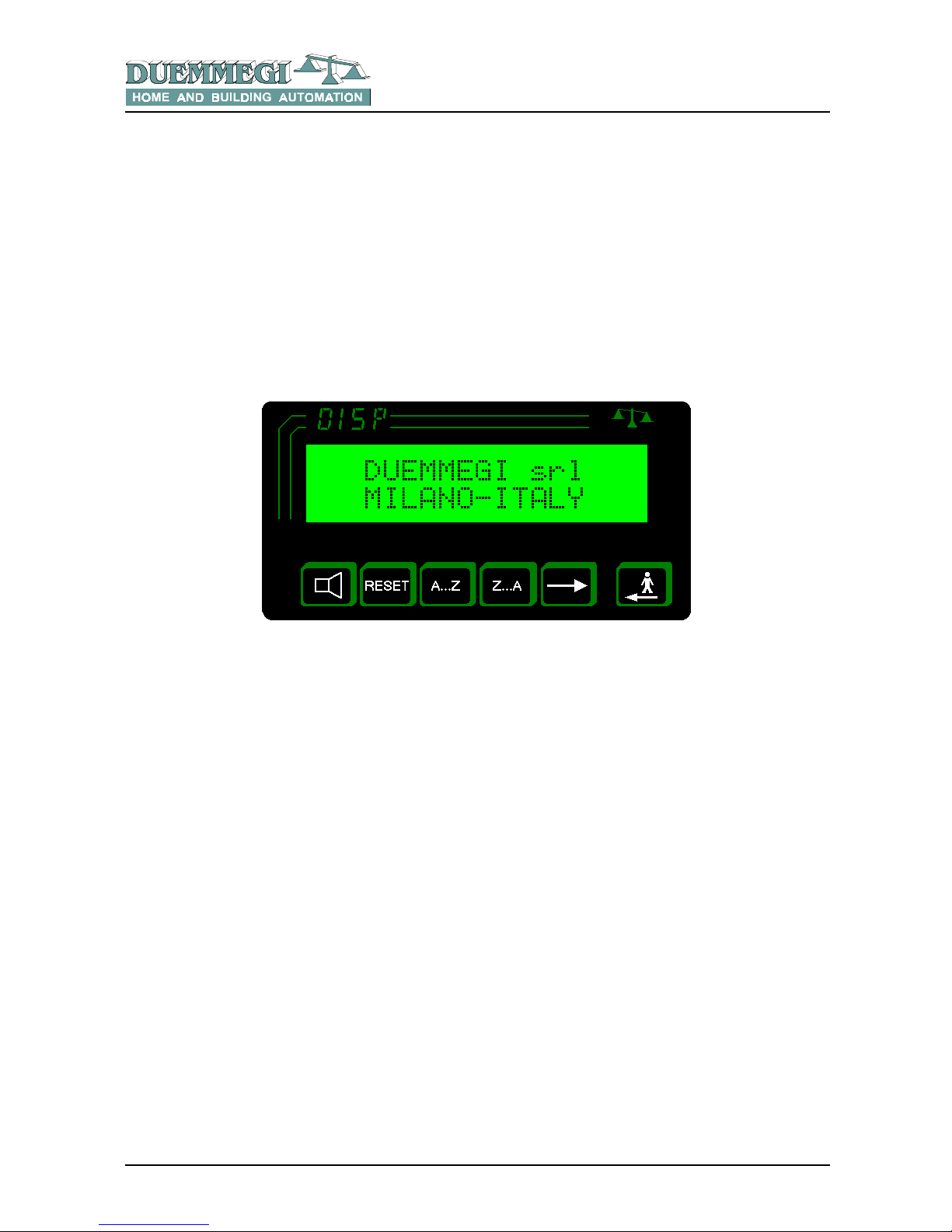
LCD display 2 x 16 characters with back-lighting
¾
1 alarm pending message made by 2 lines
¾
LCD contrast may be adjusted by the button on the
front panel
¾
Cyclic displaying of more messages; the cycle time
may be set by user in the range 1 to 10 seconds
¾
Message programming by front panel pushbuttons or
by PC
¾
Events storing (MEM) or current status display
(NOMEM)
¾
Messages and parameters stored into DISP2 memory
may be read by a PC
¾
Events are displayed in chronological order (up to 64);
information about the total amount of pending alarms
¾
The inputs may be insulated by internal photo-
couplers
¾
Internal buzzer for alarm acoustic signaling; the
buzzer operation may be disabled
¾
16 messages direct mode or 255 messages binary
mode
¾
2 potential free contacts (internal relays) for additional
acoustic/visual signaling (siren and flasher)
¾
In direct mode each input may be set for NO or NC
operation
¾
2 inputs for remote ACK and RESET commands
¾
Up to 255 messages, each one made by 2 main lines
and 2 hidden lines
¾
1 base message made by 2 lines (stand-by message)
¾
Keyboard lock to avoid unwanted operations by
unauthorized personnel
The firmware of DISP2 device may be updated directly by the user through a PC and the RS232 communication port;
this feature allows future developments of the product concerning new functions and possible special versions. For more
details about this feature, contact
DUEMMEGI
commercial office.
DISP2
Rel.: 2.0 - September 2004 - Page 3
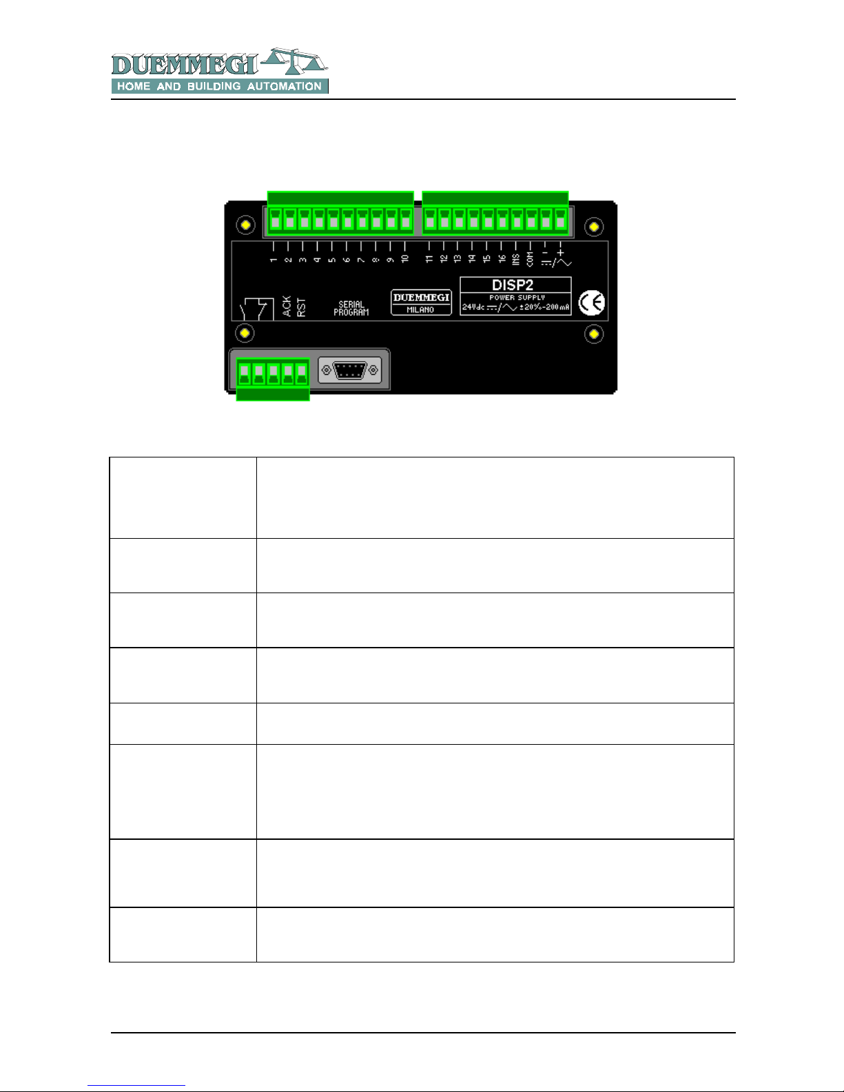
3- CONNECTIONS
The terminals of DISP2 devices have a different meaning depending on the chosen setting among direct and binary
mode. The two following tables list the meaning in the two cases.
DISP2 set for direct inputs: terminal description
1 – 16
Input terminals: each input is activated applying a positive voltage to the related terminal; if
the electrical insulation of inputs is not needed, the COM terminal must be used to supply
the inputs (through free potential contacts). The status of each input, to be accepted, must
be stable for 50 msec minimum.
INS
This terminal allows the electrical insulation of the inputs (see next paragraph); connect
this terminal to 0V of the external voltage source used to supply the input terminals
COM
Positive voltage output to be used as common terminal of the contacts connected to the
inputs
SUPPLY
Power supply input: 24 Vac/dc ± 20% (refer to the shown polarity when supplied by a dc
source)
SERIAL PROGRAM
Connector for the serial programming trough a PC
OUTPUT CONTACTS
N.O.: Relay output contact for external alarm device (e.g. siren)
N.C.: Relay output contact for external alarm device (e.g. flasher)
Note: since the flasher output is a normally closed contact, then the signaling on the
flasher is guaranteed even if the power supply of DISP2 fails.
EXT ACK
Input for remote acknowledgement pushbutton; the external pushbutton must be
connected to this terminal and to «COM» (but only if the electrical insulation of the inputs
is not needed)
EXT RESET
Input for remote reset pushbutton; the external pushbutton must be connected to this
terminal and to «COM» (but only if the electrical insulation of the inputs is not needed)
DISP2
Rel.: 2.0 - September 2004 - Page 4
DISP2 set for binary code input: terminal description
1 – 8
Binary code input terminals: each input is activated applying a positive voltage to the
related terminal; if the electrical insulation of inputs is not needed, the COM terminal must
be used to supply the inputs (through free potential contacts). Each applied binary code
recalls the related message; the less significant bit is terminal 1, the most significant bit is
terminal 8. The applied binary code at terminals 1 ÷ 8 will be read by DISP2 when
STROBE input is activated. The status of each input, to be accepted, must be stable for 50
msec minimum.
9
STROBE
DISP2 reads the binary code input when this STROBE input is active (positive voltage
applied to the terminal)
12
CLEAR ALL + STROBE
Clear the current messages queue when a positive voltage is applied both to this terminal
and to the STROBE terminal
13
CLEAR ALL
Clear the current messages queue (regardless of the status of STROBE input)
14
CLEAR ONE + STROBE
At the STROBE activation, the message related to the binary code currently applied to
inputs 1 ÷ 8 will be removed
INS
This terminal allows the electrical insulation of the inputs (see next paragraph); connect
this terminal to 0V of the external voltage source used to supply the input terminals
COM
Positive voltage output to be used as common terminal of the contacts connected to the
inputs
SUPPLY
Power supply input: 24 Vac/dc ± 20% (refer to the shown polarity when supplied by a dc
source)
SERIAL PROGRAM
Connector for the serial programming trough a PC
OUTPUT CONTACTS
N.O.: Relay output contact for external alarm device (e.g. siren)
N.C.: Relay output contact for external alarm device (e.g. flasher)
Note: since the flasher output is a normally closed contact, then the signaling on the
flasher is guaranteed even if the power supply of DISP2 fails.
EXT ACK
Input for remote acknowledgement pushbutton; the external pushbutton must be
connected to this terminal and to «COM» (but only if the electrical insulation of the inputs
is not needed)
EXT RESET
Input for remote reset pushbutton; the external pushbutton must be connected to this
terminal and to «COM» (but only if the electrical insulation of the inputs is not needed)
 Loading...