

Duemmegi Contatto ModLC-WM, Contatto ModLC-WM-P User Manual
Contatto
ModLC-WM / ModLC-WM-P
ModLC-WM / WM-P: ambient light regulator
module with integrated sensors for Brightness and Presence (-P version)
ModLC-WM module allows to transmit, over the Contatto
bus, the ambient brightness value detected by the sensor
integrated inside the module itself. This module provides a
PID algorithm for the automatic regulation of the ambient
brightness and some SMART modes, thus allowing to considerably simplify the programming of the MCP controller
when realizing these kinds of applications. ModLC-WM-P
also features a built-in presence sensor.
ModLC-WM module can thus be well applied in the brightness regulation of offices, stores and open spaces, allowing to develop applications complying with the new
European norms about the energetic classification of the
plants (European Norm EN 15232).
ModLC-WM module is suitable for wall mounting; the sensor detects the light reflected by the surface under it (for
instance the floor or a desk). The special integrated sensor
has the same spectral sensitivity of the human eye.
The module features a 7-way removable terminal block for
the connection to the Contatto bus and, if required, to
presence sensors (e.g. DUEMMEGI SRP) that must works
in parallel connection with internal sensor (if -P version).
ModLC-WM module, for its operations, can work only in
systems equipped with MCP XT or MCP 4. The housing is
plastic material with IP20 protection degree.
Note: this technical sheet applies to ModLC-WM and ModLCWM-P equipped with FW 2.5 or higher.
Address programming
ModLC-WM module takes one input address and, if enabled, one output address with the same value; the address has to be assigned by the FXPRO programmer
through the proper programming cable inserted in the connector placed inside the module.
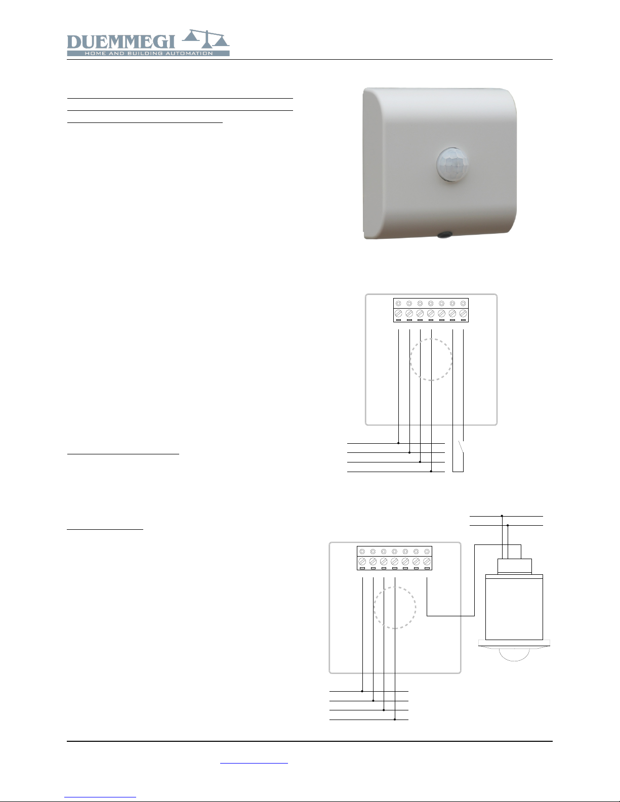
Wiring diagram
The following schematic diagram shows the connections to
the Contatto bus.
The input (IN) may be used for the connection to one or
more presence sensors that, for -P version, will work in parallel connection with the internal sensor; the contacts of
these sensors, which must be potential free, must be connected between the terminals +COM and IN.
Anyway, take in account that terminal 1 is a 24V voltage
output to supply the external contact, which, as said before,
must be potential free. The terminal 2 is the digital input of
the module and can be also activated by a continuous positive voltage, referred to 0V, inside the range 10 to 30V.
Connection to the contact of a presence sensor:
13 14 15 16 17 1 2
+24V
BUS0VL1
L2
L2
L1
0V
+24V
+COM
IN
If using a DUEMMEGI SRP presence sensor, refer to the
following schematic diagram.
13 14 15 16 17 1 2
+24V
BUS
0V
L1
L2
L2
L1
0V
+24V
+COM
IN
1 2 3 4 5
+24V
0V
DUEMMEGI s.r.l. - Via Longhena, 4 - 20139 MILANO
Tel. 02/57300377 - Fax 02/55213686 – www.duemmegi.it
Rel.: 2.5 April 2019 Page 1 of 11
Contatto
ModLC-WM / ModLC-WM-P
If more SRP presence detection modules are required, they
can be parallel connected.
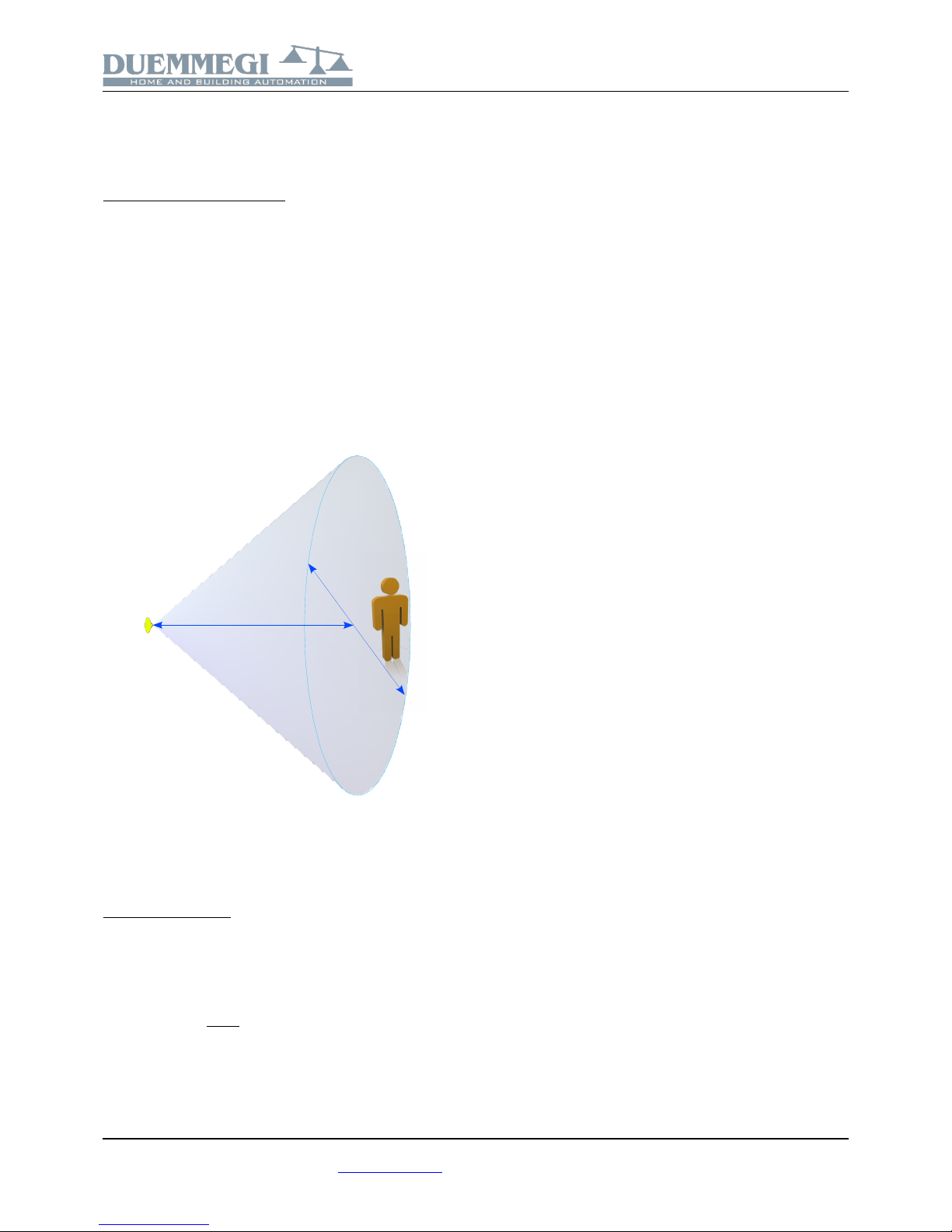
Detection characteristic
The presence sensor (-P version), as said above, can detect the movement in the range of 10 meters, in the perpendicular direction in respect to the module surface.
When a person is moving, thanks to the detection of infrared radiation emitted by the body, the sensor will be able
to detect the movement.
For the calculation of the covered area refer to the following
formula:
D = L x 2.38
where D is the diameter of the cone basis and L is the distance from the sensor, as shown in the following figure.
D
L
Therefore the detection area (cone basis) increases when
the sensor is far (inside the limit of 10 meters about); take
this in account when positioning the module.
Installation hints
The correct positioning of the sensor plays a fundamental
role in the application of automatic light regulation. Even if it
is hard to give a general rule for the positioning of the sensor, because each specific case could be evaluated, as approximated general rule the sensor could be installed on
the wall, at a height of 2.30 meters about, in a proper position avoiding the direct incidence of external light entering
from windows or other openings.
This because, on the contrary, the direct light should be
predominant in respect to the reflected light that is, at the
end, the light to be regulated (because, generally, the purpose is to make constant the illumination of the working
desks).
For instance, in the case of a room with two windows on
the same wall, the sensor may be placed on the same wall
between the two windows, with sensor toward the interior
of the room. Also, a “stable” surface must be “seen” by the
sensor: this surface must be at a constant distance from
the sensor and it must have always the same color (it may
be the floor or a desk or other). Take in account that the
sensor is oriented 45 degrees about in respect to the wall.
The height and position for proper installation must be however evaluated taking in account also the presence sensor
and the physical shape of the room. Given that the presence detection is based on the detection of infrared emissions, it is good practice to take in account also the
following aspects related to the use and to the installation
of ModLC-WM-P module, in order to avoid errors in the detection by the sensor itself.
Detection of heat sources other than a human body
The following cases show various situations where detection mistakes by the detection sensor may happen.
✗ small animals entering in the detection range
✗ infrared emissions from sunlight, incandescent light or
some other sources of far infrared rays
✗ sudden change of the temperature due to the entry of
cold or warm air from an air-conditioning or heating
unit or water vapor from a humidifier
Bad conditions for the detection
✗ the detection of movement by the sensor could be dis-
turbed by the presence of glasses objects, acrylic or
other materials that may shield the infrared rays
✗ a heat source not moving or moving too quickly or
moving too slowly may be undetected by the sensor
✗ the sensor is less sensible when the temperature of
the moving body is near to the ambient temperature
Other handling cautions
✗ be careful to keep clean from dust or dirt accumulating
on the lens because this will adversely affects the detection sensitivity
✗ the lens is made by a soft material (polyethylene);
avoid applying a load or impact since this will deform
or scratch the lens
✗ to cleaning the sensor avoid the use of fluids that may
enter inside the sensor causing a deterioration
To install ModLC-WM sensor, follow the steps here bottom
described.
DUEMMEGI s.r.l. - Via Longhena, 4 - 20139 MILANO
Tel. 02/57300377 - Fax 02/55213686 – www.duemmegi.it
Rel.: 2.5 April 2019 Page 2 of 11
Contatto
ModLC-WM / ModLC-WM-P
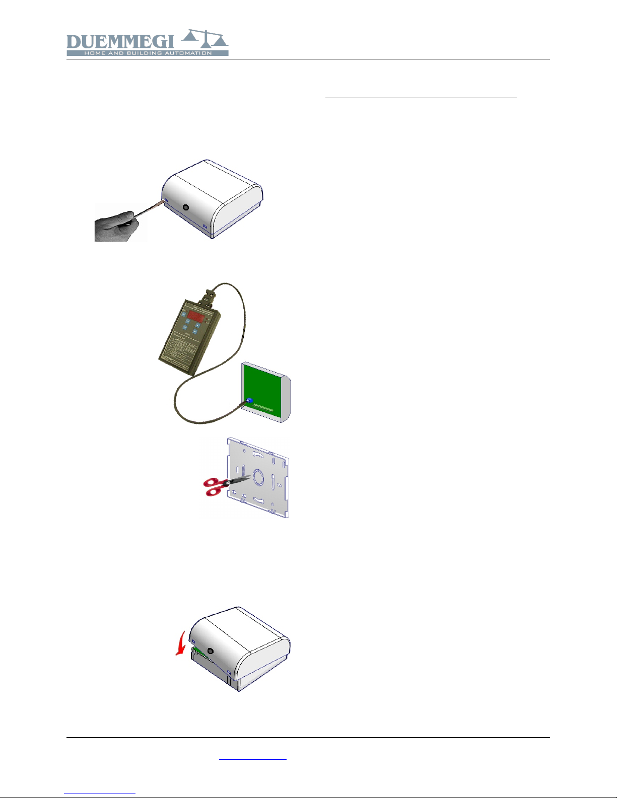
Opening of the module
Find the two fissures where the small dull tooths of the rear
panel are housed (normally on the bottom side). Insert the
tip of a small screwdriver in one of these fissures so that
the rear panel releases towards the outside. Then insert
the screwdriver in the other fissure so to extract completely
the rear panel.
Address assignment
Insert the proper connector of FXPRO programmer in the
blue connector on the
rear side of the electronic card and assign
the base address following the normal procedure of all Contatto
modules.
Connection
Open the hole on the rear panel
helping yourself with a small pincers or a pair of scissors. Insert
the wires (those of the bus and
eventually those of the input) in
the hole of the rear panel; fix the
rear panel to the wall, placing attention to its orientation (see the
UP label on the rear panel itself).
Be sure that no voltage is present on the wires.
Connect the wires to the terminal blocks of the electronic
card according to schematic diagram.
Closing of the module
Place the top side of the cover on the rear panel fixed to
the wall, so that the two tooths on the top side of the rear
panel itself fit in the related
fissures and, at the same
time, the connector of the
electronic card fits into the
terminal block. At this
point, delicately push the
bottom side of the cover
towards the rear panel,
until the two dull tooths on
the rear panel fit in the related fissures of the cover.
Automatic regulation of the brightness
ModLC-WM module features a PID regulation algorithm
(Proportional Integral Derivative). This allows to implement
a system for the automatic brightness regulation: fixed the
desired setpoint (1), ModLC-WM module will calculate autonomously the optimal value which, sent to the dimmer of
the luminous source, will allow to reach and maintain that
setpoint.
Therefore this system for the automatic regulation will con stantly follow the assigned setpoint, thus compensating the
external environmental contributions like, for instance, the
increasing or decreasing of the light quantity coming from
the windows of the room being automatically regulated.
The speed at which the regulation system reaches the setpoint can be adjusted changing the regulation parameters
Ki and Ki Fine; increasing the value of Ki (2), the system will
reach the setpoint quickly.
It is also possible to define a range around the setpoint
(Zone Ki Fine) where the control change from the normal Ki
to the Ki Fine; in this way the speed will be reduced in order to approaching to the setpoint with better precision,
avoiding as much as possible overshoots and oscillations.
Once the setpoint has been reached, the regulator will not
execute other operations during all the time the measured
value falls inside a range, called dead zone; this dead
zone, in addition to Ki and Ki Fine, can be defined during
the setting up.
ModLC-WM module also allows to define a ramp value to
be sent to the dimmer in order to avoid discontinuous light
changes, with a bad optical effect, when increasing or decreasing the brightness of the lamp.
(1): the setpoint is defined as the brightness value that the automatic regulation system has like target to be reached and maintained.
(2): an excessive speeding up of the system may generate instability events, also appearing as periodic switching on and off of the
light source.
For details about the meaning and the setting of the several
parameters available for the automatic regulation, refer to
the paragraph “Configuration of ModLC-WM module”.
DUEMMEGI s.r.l. - Via Longhena, 4 - 20139 MILANO
Tel. 02/57300377 - Fax 02/55213686 – www.duemmegi.it
Rel.: 2.5 April 2019 Page 3 of 11

Contatto
ModLC-WM / ModLC-WM-P
SMART mode
To realize a system of automatic regulation of ambient
light, with or without presence sensor, it is possible to use
ModLC-WM module in conjunction with proper programming of MCP controller, according to the application requirements.
ModLC-WM module, however, features the SMART mode
operation: in practice it is possible to choose among some
predefined modes of operation, which generally cover most
of real cases; therefore, it will be enough to select the desired SMART mode, among the available options, and the
module will autonomously manage all the operation logic
and regulation, including the management of the local
pushbutton for manual adjustment, the presence sensor,
the automatic/manual switching and so on. In this way, the
programming of MCP will be reduced to “turn” the contents
of the input channel 2 input of ModLC-WM to the dimmer
module or to ModDALI module (in the case of systems with
DALI lighting).
ModLC-WM module can therefore work in traditional way
(that means absolutely equivalent to ModLC-WM with
firmware version lower than 2.0) or in SMART mode. The
predefined SMART modes will be described in the following. In all cases, ModLC-WM will place on its input channel
2 a value or a command code to be sent to dimmer or to a
DALI group.
In the following description “One Touch” means a short
press of the local button (less than 400ms).
In all cases, adjustments and switchings can be performed
by a supervisor acting on the output points of CH4 or on
the value of output channel CH2 (see paragraph Information on the bus).
Mode SMART 1
Arrangement for the typical zone:
• ModLC-WM module
• Presence sensor of ModLC-WM
• Local button connected to Ix.y; One touch on this button
toggles between AUTO and OFF
From FW version 2.1, an option for SMART1 has been
added, depending on the status 0 or 1 of point 6 channel 4
of output address (Ox:4.6).
Operation with Ox:4.6=0:
Starting with lights OFF, the AUTO brightness regulation
will be activated at the presence detection. One Touch
pressings on the local button will toggle the system between AUTO and OFF. Long pressings on the local button
will switch the system in MANUAL mode and activate the
mono-command (the light increases or decreases for all the
time the button is pressed). When the time delay related to
the presence sensor elapses, the system will be turned off
regardless of the condition in which it was (AUTO or MANUAL).
Operation with Ox:4.6=1:
Starting with lights OFF, nothing happens at the presence
detection, because the the turn ON in AUTO mode can occur only by One Touch pressing on the local button. Successive One touch pressings will switch the system
between AUTO and OFF.
Long pressings on the local button will switch the system in
MANUAL mode and activate the mono-command (the light
increases or decreases for all the time the button is
pressed). When the time delay related to the presence sensor elapses, the system will be turned off regardless of the
condition in which it was (AUTO or MANUAL).
Mode SMART 2
Arrangement for the typical zone:
• ModLC-WM module
• Presence sensor of ModLC-WM
• Local button connected to Ix.y; One touch on this button
switches the system to MANUAL mode and toggle the
light level between 0% and K% (K = 1 to 100)
Operation:
Starting with lights OFF, the AUTO brightness regulation
will be activated at the presence detection. One Touch
pressings on the local button will switch the system to
MANUAL and they will toggle the lights alternately between
0% and K% (K must be set during configuration of ModLCWM). Long pressings on the local button will switch the
system in MANUAL mode and activate the mono-command
(the light increases or decreases for all the time the button
is pressed). When the time delay related to the presence
sensor elapses, the system will be turned off regardless of
the condition in which it was (AUTO or MANUAL).
Mode SMART 3
Arrangement for the typical zone:
• ModLC-WM module
• Presence sensor of ModLC-WM
• Local button connected to Ix.y; One touch on this button
switches the system to MANUAL mode and toggle the
light level between 0% and last stored value
Operation:
Starting with lights OFF, the AUTO brightness regulation
will be activated at the presence detection. One Touch
pressings on the local button will switch the system to
MANUAL and they will toggle the lights alternately between
0% and the last value which has been stored after a manual adjustment. Long pressings on the local button will
switch the system in MANUAL mode and activate the
mono-command (the light increases or decreases for all the
time the button is pressed). When the time delay related to
the presence sensor elapses, the system will be turned off
regardless of the condition in which it was (AUTO or MANUAL).
Mode SMART 4
Arrangement for the typical zone:
• ModLC-WM module
• Without presence sensor (it is better to use ModLC-WM
without integrated presence sensor)
• Local button connected to Ix.y; One touch on this button
toggles between AUTO and OFF
Operation:
Starting with lights OFF, a One Touch pressing on the local
button will activate the AUTO brightness regulation; anoth-
DUEMMEGI s.r.l. - Via Longhena, 4 - 20139 MILANO
Tel. 02/57300377 - Fax 02/55213686 – www.duemmegi.it
Rel.: 2.5 April 2019 Page 4 of 11
 Loading...