

DUEMMEGI
ADDRESS
Contatto
MILANO-ITALY
DMX Gateway
Power supply 24V= ±25% / 50mA
MODDMX
ON
+24V
0V
L1
L2
P
13 14 16 1715
+24V
BUS
0V
L1
L2
1 2 3
A (+)
B (-)
G
DMX
TX
XLR
HOME AND BUILDI NG AUTOMATION
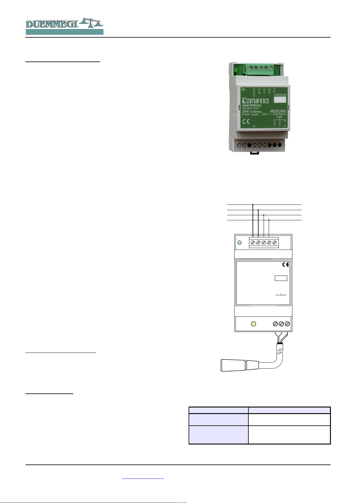
ModDMX: DMX gateway
ModDMX module allows to handle, through the Contatto
bus, up to 32 DMX devices. ModDMX module makes possible the communication on the first 64 of 512 DMX channels allowed by this protocol.
ModDMX module can be successfully employed in professional and domestic lighting applications, where systems
communicating by the USITT DMX-512 protocol are used,
as theaters, disco clubs, architectural lighting, etc.
ModDMX module features the following characteristics:
✗ all functions are managed by the module and can be
controlled by any real or virtual input of the system, by
supervisor or by video-terminal
✗ possibility to control the DMX system from one or more
pushbuttons connected to the Contatto bus
✗ up to 64 sceneries are available to realize “real time”
scenes; the sceneries are stored in the non volatile
memory of the module
✗ management of fade times
✗ management of different rooms by the same ModDMX
Contatto
ModDMX
Even if the standard specifies a maximum of 32 devices for
the DMX line, as a good rule do not override a total amount
of 16-20 devices. If the number of devices is higher than
20, use proper line splitters to connect the devices overriding this limit.
The module can manage up to 64 DMX channels, but the
total amount of connected DMX devices may be lower than
64 if the device gets more than one channel. Moreover, the
total amount of connected DMX devices may be anyway
lower than 32. ModDMX module can operate exclusively in
system using MCP XT controller. Up, Down and Single
Command function, with or without one-touch feature, can
be performed by the module from any real or virtual input of
the system (see in the following of this manual); in addition,
it is possible to save and recall the sceneries.
The module features a removable 5-way terminal block for
the connection to the Contatto bus and a fixed 3-way terminal block for the DMX line. A green LED near to the bus
terminal block shows that the module is supplied, while a
yellow LED near to the 3-way terminal block shows the
presence of communication on the DMX line. ModDMX is
housed in a standard DIN 3M box for rail mounting.
Note: this manual applies to ModDMX modules equipped by
firmware version 2.2 or higher.
Address programming
ModDMX module takes 1 output address, 1-channel 16-bit.
The address must be assigned by FXPRO programmer. A
white label on the front panel allows the writing of the assigned address for an immediate visual identification.
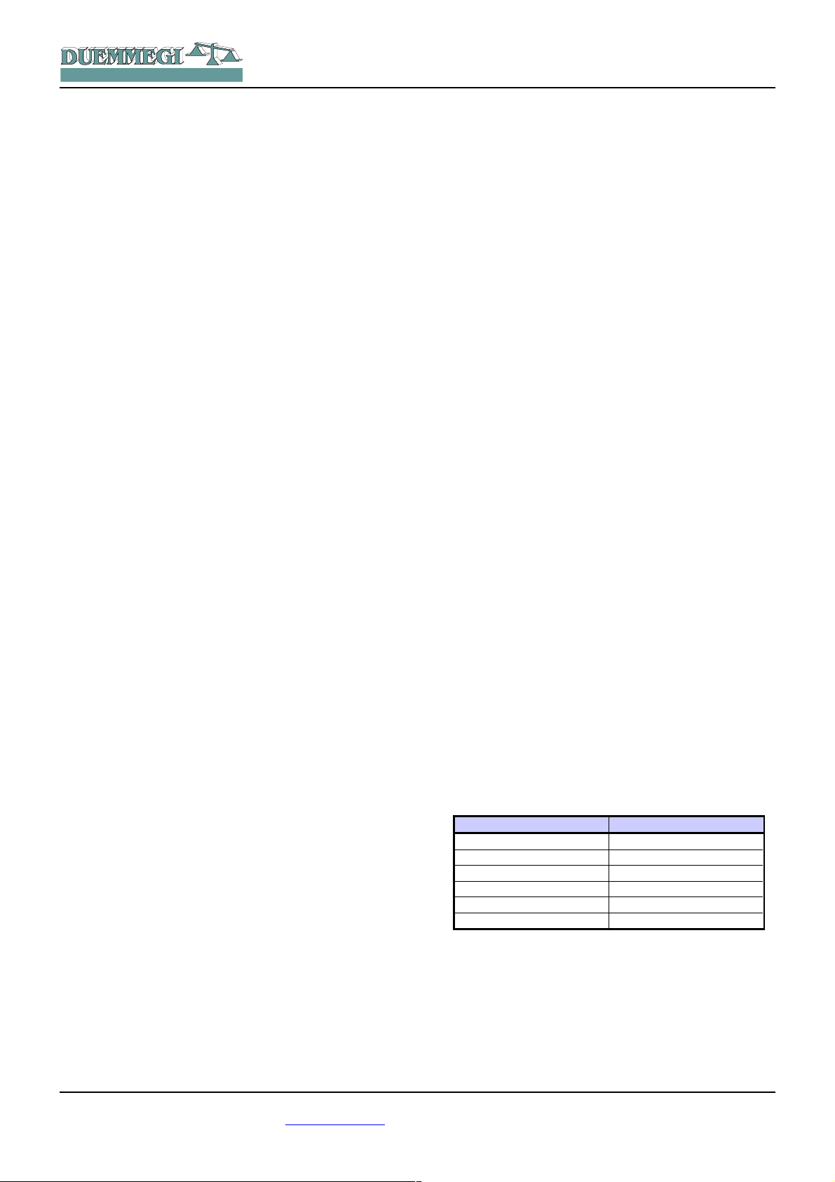
Wiring diagram
The following schematic diagram shows the connection to
be made between ModDMX module, the Contatto bus and
the DMX line, using proper cables as described in the related table.
Generally, the DMX devices feature a female XLR 5-way or
3-way connector, therefore in this case the cable of
ModDMX must be properly wired to a male XLR connector
(not provided) according to the specification of the manufacturer of the device.
The following table provides some suggestions about the
cables to be used for the connections and the related maximum length.
Connection Suggested cable
Contatto bus
DMX line
4 x 2.5 mmq MAX not shielded,
MAX 1.5Km
2 twisted pairs 2 x AWG22 MIN
(e.g.: Belden 3107A or 9841 or
CEAM CPR6003), MAX 1Km
DUEMMEGI s.r.l. - Via Longhena, 4 - 20139 MILANO
Rel.: 2.2 December 2013 Page 1 of 7
Tel. 02/57300377 - Fax 02/55213686 – www.duemmegi.it

HOME AND BUILDI NG AUTOMATION
Contatto
ModDMX
For the DMX connections always use cables specified for
EIA RS485 communication, with 120 ohm impedance and
low coupling capacitance between the cores. Use a twisted
pair for the lines A and B. Do not connect the shield of the
DMX cable; use another pair to connect the G terminal
(ground) of ModDMX and of the various connected
devices. Do not connect any DMX cable (G terminal included) to the protective earth, because this can inject
some disturbances causing negative effects on the communication.
All DMX devices must be connected in sequential way; absolutely avoid star connections. The DMX line must be terminated at its start and at its end by a 120 ohm resistor (not
provided), as recommended by RS 485 specifications.
Bus commands
As said before, ModDMX takes 1 output address, 1-channel 16-bit, inside Contatto bus. The following table describes the meaning of the data field:
Bit Data field at the output address
1
2
3
4
5
6
7
8
9
10
11
12
13
14
15
16
Command Code
Granted that DMX channel are numbered 1 to 64, the same
DMX channels will be managed through the output address
of ModDMX module.
Considering the 16 bits as group of 2 bytes, the most significant byte represents the command code to be executed,
while the less significant byte set the value or the scenery
number or the channel number depending on the specific
command to be executed.
The following table lists the allowed command codes.
Value
or
Scenery Number
or
Channel Number
Command Code
DEC HEX Function
0 0x00
1 ÷ 64 0x01 ÷ 0x40
101 0x65
102 0x66
103 0x67
111 0x6F
112 0x70
113 0x71
125 0x7D
126 0x7E
127 0x7F
128 0x80
129 0x81
130 0x82
131 0x83
133 0x85
134 0x86
135 0x87
136 0x88
140 0x8C
255 0xFF
No operation (stop Up/Down and
Single Command)
Select DMX channel on which the
value specified by the low byte has
to be written
Save the current status of the (included) channels into the scenery
specified by the low byte
Include the channel specified by the
low byte in the next scenery that will
be saved; if the low byte is 0, then
all channels will be included
Exclude the channel specified by
the low byte in the next scenery that
will be saved; if the low byte is 0,
then all channel will be excluded
Recall the scenery specified by the
low byte
Disable the DMX flux; the value of
the low byte has not influence
Enable the DMX flux; the value of
the low byte has not influence
Up command without one-touch on
the CH specified by the low byte
Down command without one-touch
on the CH specified by the low byte
Single command without one-touch
on the CH specified by the low byte
No operation (stop Up/Down and
Single Command)
Up command with one-touch on the
CH specified by the low byte
Down command with one-touch on
the CH specified by the low byte
Single command with one-touch on
the CH specified by the low byte
Switch off (write zero) the DMX
channel specified by the low byte
and store the last value
Recall the last stored value on DMX
channel specified by the low byte
(switch on to last value)
Set as DMX minimum level the
value specified by the low byte
Set as DMX maximum level the
value specified by the low byte
Set as ramp time the value specified
by the low byte, according to the
table reported in the following
Broadcast command: send to all
DMX channels the value specified
by the low byte
Some of the more used codes will be described in the following of this paragraph.
Writing a value on a channel
For codes 1÷64 (write a value on a channel) the allowed
range for the value is 0 to 255, taking in account the type of
the connected DMX device, which can be a RGB spot, a
rotating light machine or others. For this reason, regarding
the meaning of each value, always refer to the manual of
the connected DMX devices.
DUEMMEGI s.r.l. - Via Longhena, 4 - 20139 MILANO
Tel. 02/57300377 - Fax 02/55213686 – www.duemmegi.it
Rel.: 2.2 December 2013 Page 2 of 7
HOME AND BUILDI NG AUTOMATION
Contatto
ModDMX
To send a well defined value to a well defined DMX channel at the pushing of a button connected to an input module
of Contatto bus, supposed to have assigned the address
127 to ModDMX module, the simplest way is to insert in the
program of MCP XT an equation similar to the following:
AO127:1 = P(0x0164)I1.1 & P(0x0100)I1.2 & \
P(0x0200)I1.3 & P(0x02FF)I1.4 & \
P(0x0300)I1.5 & P(0x03FF)I1.6
where I1.1..I1.6 are the inputs connected to pushbuttons and AO127:1 is the channel 1 of ModDMX module
(supposing 127 as address).
The values loaded by the Preset (P) function at the activation of an input, in the 16-bit hexadecimal format, will be interpreted as follows: the high byte shows the DMX channel
on which the value specified by the low byte ha to be
loaded. Therefore, at the activation of the input I1.1 the
value 0x0164 will be sent to the module, corresponding to
load the value 100 (decimal equivalent of 0x64) on the
DMX channel 1. In the same way, at the activation of input
I1.4, the value 255 (0xFF) will be loaded on the DMX
channel 2 DMX, and so on. The values allowed for DMX
channels, as said before, must be in the range 0 to 255,
and the meaning depends on the type of connected DMX
device.
If a 3-channels RGB device is connected, this taking the
first 3 DMX channels, different values loaded on these
channels could allow, for instance, to reproduce 2563 =
16.777.216 colors.
In this same example, to generate a succession of random
colors, the following simple script and equation can be
used, and this shows the potentiality of MCP XT controller
and of ModDMX module. V1 simply generates a “clock” to
recall the script every 1 second.
script 1
trigger = V1
R0 = RANDOM(0)
R0 = R0 & 0X00FF
R0 = R0 | 0x0100
AO127:1 = R0
R0 = RANDOM(0)
R0 = R0 & 0X00FF
R0 = R0 | 0x0200
AO127:1 = R0
R0 = RANDOM(0)
R0 = R0 & 0X00FF
R0 = R0 | 0x0300
AO127:1 = R0
endscript
V1 = TIMER(!V1,5,5)
Up, Down and Single Command functions
These control functions, with one-touch feature, are those
typical of the conventional dimmer modules of the Domino
family and they will be described here in the following.
Up/Down pushbuttons: pushing and holding Up (Down)
button, the brightness increases (decreases) until the max
(min) value is reached. When the brightness has reached
the desired level, release the button to hold it.
Single Command: holding down the button, the brightness
increases until the max value is reached and, after 1
second about, the brightness decreases to the min value,
then it increases again and so on. Release the button at
the desired level to hold it.
When the lamp is ON, a short pulse (one-touch) on any
control button will cause the complete switching OFF.
When the lamp is OFF, a short pulse on any control pushbutton will cause the switching ON at the last brightness
level.
In the following example, at the pushing of one of the 3 buttons, the single command code (0x83) will be sent to the
channel specified by the low byte (01, 02 or 03). When releasing the button, the stop code (0x80, 0x00 can be also
used) will be sent to the same channel, allowing the module to understand that the button has been released.
AO127 = P(0x8301)I1.1 & P(0x8001)!I1.1 & \
P(0x8302)I1.2 & P(0x8002)!I1.2 & \
P(0x8303)I1.3 & P(0x8003)!I1.3
To use the Up and Down functions instead of the single
command, simply use the related codes (0x81 and 0x82 respectively).
Ramp or fade time
For ramp, or fade time, it is intended the time required to
change a channel value from 0 to 255. The allowed fade
times are in the range 0 to 255; it is possible to set the desired fade time according to the following relationship:
Fade Time = Value x 255 x0,01 [seconds]
The fade time is always the same for all the 64 DMX channels; to set it, use the command 140.
The Fade Time is given in seconds. The following table
shows the relationship between some values that can be
written at the output address +1 and the related fade time.
Set value Fade time [sec]
0 0
1 2,55
2
3 7,65
.... ....
255 650,25 (10' and 50” about)
Note 1: it is not possible to set a different fade time for each channel; in other words, the fade time is a global parameter.
Note 2: the regulation through Up, Down and Single Command
uses a fixed ramp time, so it cannot be modified.
5,10
DUEMMEGI s.r.l. - Via Longhena, 4 - 20139 MILANO
Tel. 02/57300377 - Fax 02/55213686 – www.duemmegi.it
Rel.: 2.2 December 2013 Page 3 of 7

HOME AND BUILDI NG AUTOMATION
Contatto
ModDMX
Sceneries, inclusion and exclusion of channels
The function for inclusion and exclusion of a channel from a
scenery allows the independent management of different
rooms using the same ModDMX module. In other words,
this feature allows to recall a scenery, e.g. related to a
room to which some DMX channels have been reserved,
avoiding to influence the current status of the other rooms
to which some other channels have been reserved.
The codes 102 and 103 (0x66 and 0x67) allow to select
which DMX channels will be included in the scenery under
construction. The less significant byte written at the output
address specifies the number of the DMX channel to be included or excluded.
The codes 101 and 111 (0x65 and 0x6F) allow to store and
recall up to 64 sceneries. The less significant byte written
at the output address specifies the number of the scenery
to be saved or recalled.
The following simple equation stores 3 sceneries (1, 2 and
64) at the pushing of 3 different buttons (I1.1..I1.3) and it
recalls them by other 3 buttons (I1.4..I1.6):
AO3:1 = P(0x6501)I1.1 & P(0x6502)I1.2 & \
P(0x6540)I1.3 & P(0x6F01)I1.4 & \
P(0x6F02)I1.5 & P(0x6F40)I1.6
To include the channel NN in the scenery, send the command 0x66NN. If NN = 0 then all the channels will be included.
To exclude the channel NN in the scenery, send the command 0x67NN. If NN = 0 then all the channels will be excluded.
Enable and disable DMX flux
To enable and disable the communication (or flux) from
ModDMX to the connected DMX devices, commands 113
and 112 can be respectively used (0x71 and 0x70). This allows to execute a sequence of DMX commands in a unique
flux, in order to avoid undesired effects. The following script
shows an example of the using of this command for the
control of DMX flux.
script 1
trigger = I1.1
AO3 = 0x7000
AO3 = 0x01FF
AO3 = 0x02FF
AO3 = 0x03FF
AO3 = 0x7100
endscript
At the activation of the input I1.1 the script executes, in
the sequence, the following functions:
✗ disabling of DMX flux
✗ loading in the memory of ModDMX of 3 values into 3
different DMX channels (but these ones will not be still
sent to the connected devices because the flux is disabled)
✗ enabling of DMX flux: at this point ModDMX will trans-
fer the value of the channels to the connected devices
Set minimum and maximum value
The commands 135 and 136 (0x87 and 0x88) allow to set a
minimum and a maximum value on all DMX channel for the
functions Up, Down and Single Command.
Broadcast command
The command 255 allows to send a value to all DMX channels at the same time.
Sceneries management by MCP IDE
As said, ModDMX module can store and recall up to 64
sceneries. This paragraph describes the management of
these sceneries and other functions by the specific configuration panel (or tool) inside MCP IDE software package
(release 3.0.0 or higher); in this case the management of
ModDMX will be executed by a PC connected to the Cont-
atto bus through MCP XT.
Notes:
✗ ModDMX module can work only if the MCP XT controller has
been installed; the configuration and the programming of
MCP XT requires the software package MCP IDE release
3.0.0 or higher.
✗ Take in account that the main purpose of DMXTools program
is for the sceneries management during the setting up and
the maintenance of the plant; it is also useful as “evaluation
program” to get confidence with ModDMX module, but the
“real” management of the plant must be executed by a proper
supervision program taking in account the global requirements of the structure property.
To use the tools, all ModDMX modules installed in the plant
must be declared in the MCP XT configuration, specifying
the addresses as in the following example:
MODDMX = ( O100 )
MODDMX = ( O101 )
MODDMX = ( O102 )
… … … …
From the menu of MCP IDE select Programming, then
Module Configuration and then MODDMX 2.x. The window
in Figure 1 will be shown.
This panel features 64 sliders, each one related to the first
DMX channels, and an additional slider (T) for the adjustment of the “Fade” or ramp time. The text box on the upper
left corner of the window ( ) allows
to enter the address of the module to be managed.
Each slider reports the number of the DMX channel
to which it is referred (1 in the example of the figure
on this left side) and it allows to change the value of
the channel playing by the mouse on the cursor of
the slider (holding down the left button); the value of
the channel is also displayed by the number on the slider
(80 in the example). As an alternative, it is possible to
double click on the value to enter the desired value and
then press Enter on the keyboard.
DUEMMEGI s.r.l. - Via Longhena, 4 - 20139 MILANO
Tel. 02/57300377 - Fax 02/55213686 – www.duemmegi.it
Rel.: 2.2 December 2013 Page 4 of 7

HOME AND BUILDI NG AUTOMATION
Contatto
ModDMX
By a double click on the channel label, the background of
this will assume white or gray color, respectively meaning
the inclusion or the exclusion of that channel.
In the following figure the channels 1, 2 and 3 are included,
while the channels 4 and 5 are excluded.
To simplify the management of RGB spot, it is possible to
assign these 3 colors to different channels (1, 2 and 3 in
the previous figure). The numbers of the channels to which
the RGB colors have been assigned are also shown in the
3 text box on the left in the previous figure; the RGB assignment to different channels can be done also writing
directly in those text boxes.
As an alternative, by double clicking on the background of
a slider, the RGB colors will be assigned to that channel
and to the following two.
The just seen RGB assignment allows to easily set on the
RGB spot the desired color chosen on the color palette that
will be opened by clicking on the colored square under the
RGB text boxes.
The following figure shows the classic color palette (the
language depends on the operating system).
The buttons 1 to 64 near to the icon allow to transfer
the values currently displayed in the window to ModDMX
and to store the current situation as scenery whose number
is equal to the number of the pressed button.
In analogous way, the buttons 1 to 64 near to the icon
allow to recall the related scenery stored in the ModDMX
module memory. These functions also include the fade
time for each scenery and information about the included
and excluded channels.
Figure 1: Tool for ModDMX
DUEMMEGI s.r.l. - Via Longhena, 4 - 20139 MILANO
Tel. 02/57300377 - Fax 02/55213686 – www.duemmegi.it
Rel.: 2.2 December 2013 Page 5 of 7

HOME AND BUILDI NG AUTOMATION
90mm
58mm
DUEMMEGI
ADDRESS
Contatto
MILANO-ITALY
DMX Gateway
Power supply 24V= ±25% / 50mA
MODDMX
ON
+24V
0VL1L2
P
13 14 16 1715
1 2 3
A (+)
B (-)
G
DMX
TX
53mm
Contatto
ModDMX
It is also possible to save into a file the scenery currently
displayed in the window (button To File); each file can contain only one scenery, thus, if more sceneries have to be
saved, it is required to create more files; these ones must
have .DMX extension.
To recall a scenery from a file and display it on the window,
use the button From File.
On the right side of the window can be found the following
controls:
✗ Read and Program respectively to read the current
situation of ModDMX and report it into the window and
to transfer the values currently displayed on the window to ModDMX module
✗ ID & Ver. To show the FW version of ModDMX module
✗ From File and To File respectively to open a file con-
taining a scenery and to save the scenery currently
displayed in the window into a file
✗ All '0' to reset to 0 all the sliders
✗ Include All and Exclude All respectively to include or
exclude all channels from a scenery
✗ MIN and MAX to read (Read) or write (Program) re-
spectively the minimum and the maximum value assigned to ModDMX module
✗ Close to close the ModDMX tool
The command to the module (Code + Val/Sc/Ch) will be
sent only after the value for Val/Sc/Ch has been written
and confirmed by Enter on the keyboard.
As usual, the symbol of the module in the map will have
green background if it is connected and properly operating,
on the contrary the background will be in red color.
Technical characteristics
Supply voltage
MAX current consumption 50mA
DMX channels 64
Managed DMX devices 32 MAX, suggested 16
Number of sceneries 64
Fade time 0 to 650.25 seconds, step 2.55
Operating temperature
Storage temperature
Protection degree IP20
24V ± 25% SELV
seconds
-10 ÷ +50 °C
-30 ÷ +85 °C
Outline dimensions
Mapping
MCP Ide allows to show the map of ModDMX module as in
the following figure:
The first text box on the top (1 in the example) is the address of ModDMX which is communicating with MCP Ide.
Code is the value of the code to be sent to to ModDMX
module (high byte of the Word to be sent, see the bus command table).
Val/Sc/Ch is the value or the scenery number or the channel associated to the just explained Code (low byte of the
Word to be sent to the module).
The box DEC allows to change the entering method for
Code and Val/Sc/Ch among decimal and hexadecimal;
with the mouse pointer on this box, right click and perform
the desired choice.
DUEMMEGI s.r.l. - Via Longhena, 4 - 20139 MILANO
Tel. 02/57300377 - Fax 02/55213686 – www.duemmegi.it
Rel.: 2.2 December 2013 Page 6 of 7

HOME AND BUILDI NG AUTOMATION
Contatto
ModDMX
Correct disposal of the product (waste electrical & electronic
equipment)
(Applicable in the European Union and other
European countries with separate collection systems). This marking on the product, accessories or
documentation indicates that the product and its
electronic accessories should not be disposed of
with other household waste at the end of their working life. To prevent possible harm to the environment or human
health from uncontrolled waste disposal, please separate these
items from other types of waste and recycle them responsibly to
promote the sustainable reuse of material resources.
Household users should contact either the retailer where they purchased this product, or their local government office, for details of
where and how they can take these items for environmentally safe
recycling. Business users should contact their supplier and check
the terms and conditions of the purchase contract. Adequate disposal of the decommissioned equipment for recycling, treatment
and environmentally compatible disposal contributes in preventing
potentially negative effects on the environment and health and promotes the reuse and/or recycling of equipment materials. Abusive
product disposal by the user is punishable by law with administrative sanctions.
Installation and use restrictions
Standards and regulations
The design and the setting up of electrical systems must be performed according to the relevant standards, guidelines, specifications and regulations of the relevant country. The installation,
configuration and programming of the devices must be carried out
by trained personnel.
The installation and the wiring of the Contatto bus line and the related devices must be performed according to the recommendations of the manufacturers (reported on the specific data sheet of
the product) and according to the applicable standards.
All the relevant safety regulations, e.g. accident prevention regulations, law on technical work equipment, must also be observed.
Safety instructions
Protect the unit against moisture, dirt and any kind of damage during transport, storage and operation.
Do not operate the unit outside the specified technical data.
Never open the housing. If not otherwise specified, install in closed
housing (e.g. distribution cabinet).
Earth the unit at the terminals provided, if existing, for this purpose.
Do not obstruct cooling of the units.
Setting up
The physical address must be assigned with the specific programmer and the setting of parameters (if any) must be performed by
the specific configuration softwares; for more details refer to the
specific data sheet of the product. For the first installation of the
device, generally and unless otherwise specified on the specific
data sheet of the product, proceed according to the following
guidelines:
• Check that any voltage supplying the plant has been removed
• Assign the address to module (if any)
• Install and wire the device according to the schematic dia-
grams on the specific data sheet of the product
• Only then switch on the 230Vac supplying the bus power sup-
ply and the other related circuits
Applied standards
The devices belonging to Contatto line comply with the essential
requirements of the following directives:
2004/108/CE (EMC)
2006/95/CE (Low Voltage)
2002/95/CE (RoHS)
Note
Technical characteristics and this data sheet are subject to change
without notice.
DUEMMEGI s.r.l. - Via Longhena, 4 - 20139 MILANO
Tel. 02/57300377 - Fax 02/55213686 – www.duemmegi.it
Rel.: 2.2 December 2013 Page 7 of 7
 Loading...