

Duemmegi Contatto MCP 4 User Manual
DUEMMEGI
Contatto
Contatto
Contatto
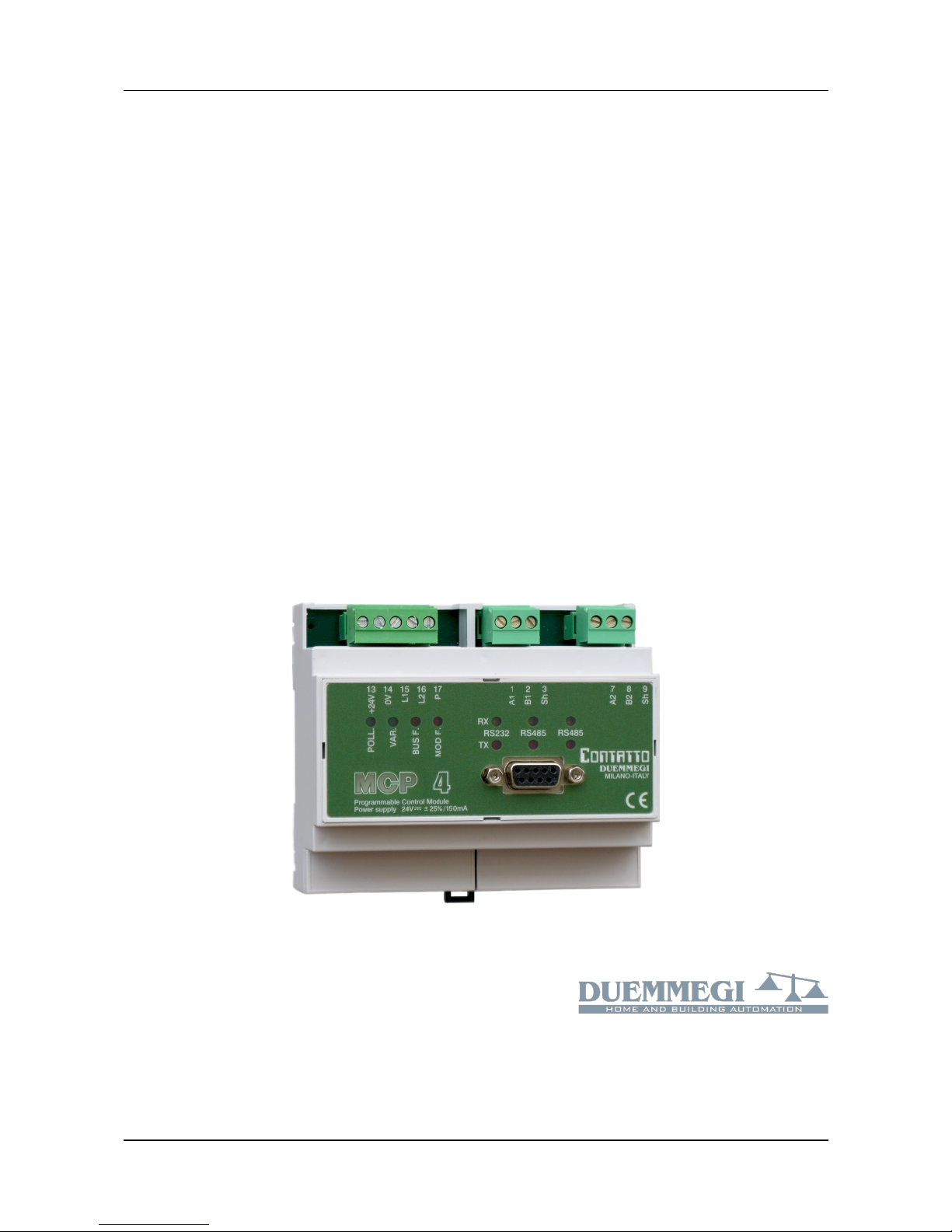
MCP 4
MCP 4
Programmable Control Module
User's Manual
Release 1.2 – October 2018
Via Longhena 4 - 20139 MILANO
Tel. 02/57300377 - FAX 02/55213686
www.duemmegi.it

Contatto
MCP 4 – User's manual
DUEMMEGI
INDEX
A1- LIST OF REVISIONS OF THIS MANUAL..............................................................................................................4
A2- RECOMMENDATIONS..........................................................................................................................................4
A3- NEWS OF MCP 4 AGAINST MCP XT AND AVAILABLE VERSIONS..................................................................5
1- MAIN FEATURES.....................................................................................................................................................6
1.1- Required Hardware and Software tools...........................................................................................................6
1.2- Main features of MCP 4....................................................................................................................................6
1.3- Terminology and syntax...................................................................................................................................7
2- EQUATIONS: TYPES AND SYNTAX.......................................................................................................................8
2.1- Equations for the system configuration............................................................................................................8
2.1.1- Configuration of the modules.............................................................................................................8
2.1.2- Power ON status................................................................................................................................8
2.1.3- Status of fault input modules..............................................................................................................8
2.1.4- Communication Protocol....................................................................................................................9
2.1.5- Address of MCP 4............................................................................................................................11
2.1.6- Identifier of MCP 4............................................................................................................................11
2.1.7- Directive for the calculation of sunrise, sunset and sun position.....................................................11
2.1.8- Publishing on the bus the status of virtual points and value of registers........................................12
2.1.9- Management of fault modules..........................................................................................................12
2.1.10- Alignment of the outputs.................................................................................................................12
2.1.11- Data exchange between MCP 4 controllers...................................................................................13
2.1.12- Number of nodes in a MCP 4 network...........................................................................................15
2.1.13- Scheduler........................................................................................................................................16
2.2- Event triggered Equations..............................................................................................................................17
2.2.1- Logic equations................................................................................................................................17
2.2.2- SET – RESET equations..................................................................................................................17
2.2.3- TOGGLE equations..........................................................................................................................18
2.2.4- COUNTER Equations.......................................................................................................................18
2.2.5- THRESHOLD Equations..................................................................................................................20
2.2.6- TIMER Equations.............................................................................................................................20
2.2.7- Equations for mathematical and logic calculation............................................................................21
2.2.8- Equations for binary code generation..............................................................................................22
2.2.9- Equations for recording status changes (EVENT)...........................................................................23
2.2.10- Equations for recording value changes (LOG)...............................................................................24
2.2.11- Management of the external counter modules (ModCNT).............................................................25
2.2.12- Management of DALI module (ModDALI)......................................................................................25
2.3- Time triggered Equations...............................................................................................................................27
2.3.1- Scheduler Equations........................................................................................................................27
2.4- Macro..............................................................................................................................................................29
3- SCRIPT...................................................................................................................................................................31
3.1- Summary.........................................................................................................................................................31
3.2- Keywords and syntax.....................................................................................................................................32
3.2.1- Using the TRIGGER.........................................................................................................................32
3.2.2- VAR, GLOBAL VAR and EXTERN VAR..........................................................................................33
3.2.3- Logic and Mathematical operations.................................................................................................33
3.2.4- IF…THEN…ELSE…ENDIF..............................................................................................................34
3.2.5- CARRY and ZERO...........................................................................................................................35
3.2.6- DEFINE.............................................................................................................................................35
3.2.7- GOTO...............................................................................................................................................37
3.2.8- SUBROUTINES and FUNCTIONS..................................................................................................37
3.2.9- BIT(x)................................................................................................................................................40
3.2.10- WORD(x) and pointers...................................................................................................................42
Page 2 of 87 Rel.: 1.2 October 2018 DUEMMEGI s.r.l. - Via Longhena, 4 – 20139 MILANO
Tel. 02/57300377 - Fax 02/55213686 – www.duemmegi.it

DUEMMEGI
MCP 4 – User's manual
Contatto
3.2.11- @RAM k and @WORD k...............................................................................................................43
3.2.12- SWAP(x).........................................................................................................................................43
3.2.13- RANDOM(0)...................................................................................................................................43
3.2.14- BMASK(x).......................................................................................................................................44
4- PROGRAM WRITING.............................................................................................................................................45
4.1- Rule for program writing.................................................................................................................................45
4.2- Compiling the program...................................................................................................................................47
4.3- Uploading the program to MCP 4 memory.....................................................................................................47
5- SETTING UP...........................................................................................................................................................48
5.1- Connections....................................................................................................................................................48
5.2- Baud Rate selection.......................................................................................................................................49
5.3- TCP/IP parameters settings (Ethernet)..........................................................................................................50
5.4- RS232 and RS485 serial ports of MCP 4......................................................................................................51
5.5- WEBS communication port............................................................................................................................51
6- DIAGNOSTICS.......................................................................................................................................................52
6.1- Diagnostics of CONTATTO system through MCP 4......................................................................................52
7- TECHNICAL CHARACTERISTICS........................................................................................................................53
8- OUTLINE DIMENSIONS.........................................................................................................................................53
9- FXP-XT COMMUNICATION PROTOCOL..............................................................................................................54
9.1- Messages format ad meaning........................................................................................................................54
9.2- RAM memory mapping...................................................................................................................................56
9.2.1- Main RAM memory mapping............................................................................................................56
9.2.2- RAM mapping of the Scheduler.......................................................................................................58
10- MCP IDE: INTEGRATED DEVELOPMENT ENVIRONMENT FOR APPLICATIONS USING MCP 4................60
10.1- Description of the software package............................................................................................................60
10.2- MCP IDE.......................................................................................................................................................60
10.2.1- MCP IDE.........................................................................................................................................64
10.2.2- Program transferring.......................................................................................................................64
10.3- MCP VISIO...................................................................................................................................................65
10.3.1- The Groups of MCP VISIO.............................................................................................................66
10.3.2- The Projects of MCP VISIO............................................................................................................69
10.3.3- The Simulator of MCP VISIO.........................................................................................................69
11- MODBUS COMMUNICATION PROTOCOL.........................................................................................................70
11.1- Abstract.........................................................................................................................................................70
11.2- Supported MODBUS functions....................................................................................................................70
11.3- Example of MODBUS functions...................................................................................................................70
11.3.1- Function 1: Reading the digital output status.................................................................................71
11.3.2- Function 2: Reading the digital input status...................................................................................72
11.3.3- Function 3: Reading the registers (RAM memory).........................................................................73
11.3.4- Function 4: Reading analog inputs.................................................................................................75
11.3.5- Function 5: Command of a single output digital point....................................................................75
11.3.6- Function 6: Writing a single register (RAM memory).....................................................................75
11.3.7- Function 16: Writing multiple registers (RAM memory).................................................................75
11.4- Tables for relationship Words-Parameters of MCP 4..................................................................................78
11.4.1- Physical inputs................................................................................................................................79
11.4.2- Physical outputs.............................................................................................................................80
11.4.3- Virtual points...................................................................................................................................81
11.4.4- Registers.........................................................................................................................................83
11.4.5- Counters.........................................................................................................................................85
DUEMMEGI s.r.l. - Via Longhena, 4 – 20139 MILANO
Tel. 02/57300377 - Fax 02/55213686 – www.duemmegi.it
Rel.: 1.2 October 2018 Page 3 of 87
Contatto
MCP 4 – User's manual
DUEMMEGI
A1- LIST OF REVISIONS OF THIS MANUAL
Rel. 1.0
First emission (MCP 4)
Rel. 1.1
Par. 2.1.4 MODBUS directives better explained
Par. 5.3 TCP/IP parameter settings better explained
Rel. 1.2
Par. 1.2 Added special virtual points V2020 to V2027 (communication lost on ETH port)
Par. 2.1.4 Added information about the management of supported MODBUS MASTER functions
Par. 11.2 Added function 4 to functions supported by MCP 4 in MODBUS MASTER mode (in addition to 3 and 16)
A2- RECOMMENDATIONS
WARNING: this manual applies to MCP 4 with the following firmwares:
Main microcontroller: 2.3 or higher
Secondary microcontroller: 1.1 or higher
The features described in this manual require the program MCP IDE release 3.2.9 or higher.
This manual assumes that the user have an adequate knowledge about the Contatto bus system.
Correct disposal of this product
(Waste Electrical & Electronic Equipment)
(Applicable in the European Union and other European countries with separate collection systems). This marking on the product,
accessories or literature indicates that the product should not be disposed of with other household waste at the end of their working life. To
prevent possible harm to the environment or human health from uncontrolled waste disposal, please separate these items from other types
of waste and recycle them responsibly to promote the sustainable reuse of material resources. Household users should contact either the
retailer where they purchased this product, or their local government office, for details of where and how they can take these items for
environmentally safe recycling. This product and its electronic accessories should not be mixed with other commercial wastes for disposal.
Specifically about the battery, check local regulations for correct disposal. Never use municipal waste.
Installation and use restrictions
Standards and regulations
The design and the setting up of electrical systems must be performed according to the relevant standards, guidelines, specifications and regulations of the
relevant country. The installation, configuration and programming of the devices must be carried out by trained personnel. The installation and the wiring of
the bus line and the related devices must be performed according to the recommendations of the manufacturers (reported on the specific data sheet of the
product) and according to the applicable standards. All the relevant safety regulations, e.g. accident prevention regulations, law on technical work equipment,
must also be observed.
Safety instructions
Protect the unit against moisture, dirt and any kind of damage during transport, storage and operation. Do not operate the unit outside the specified technical
data. Never open the housing. If not otherwise specified, install in closed housing (e.g. distribution cabinet). Earth the unit at the terminals provided, if
existing, for this purpose. Do not obstruct cooling of the units. Keep out of the reach of children.
Setting up
The physical address assignment and the setting of parameters (if any) must be performed by the specific softwares provided together the device or by the
specific programmer. For the first installation of the device proceed according to the following guidelines:
Check that any voltage supplying the plant has been removed
Assign the address to module (if any)
Install and wire the device according to the schematic diagrams on the specific data sheet of the product
Only then switch on the 230Vac supplying the bus power supply and the other related circuits
Applied standards
This device complies with the essential requirements of the following directives:
2004/108/CE (EMC)
2006/95/CE (Low Voltage)
2002/95/CE (RoHS)
EN 55022 Class B
Note
Technical characteristics and this data sheet are subject to change without notice.
Page 4 of 87 Rel.: 1.2 October 2018 DUEMMEGI s.r.l. - Via Longhena, 4 – 20139 MILANO
Tel. 02/57300377 - Fax 02/55213686 – www.duemmegi.it

DUEMMEGI
MCP 4 – User's manual
Contatto
A3- NEWS OF MCP 4 AGAINST MCP XT AND AVAILABLE VERSIONS
Hardware:
• Fastest processors and memories
• Added one RS485 communication port (COM4)
• Added Ethernet connection
• Removed alarm relay
Functions:
• Integrated weekly Scheduler for management of 16 points ("zones") with 8 time slots each one; each
time slot can be individually enabled or disabled
• A new program transferred to MCP 4 is stored in a different memory location and therefore, during
the download, the program previously loaded continues to operate without interruption; only when
downloading of the new program is completed, and if everything goes well, the automatic switch from
the old program to the new one will be performed.
• MODBUS TCP/IP Slave on ETH port
• Integrated Ethernet Bridge, multi-user up to 8 simultaneous connections
• Integrated WEB Server, multi-user up to 8 simultaneous connections, including sceneries
management
• Simple Diagnostic through a WEB browser, therefore without need to install MCP IDE program
The available versions are the following:
• MCP 4/STD: 1 RS232 + 2 RS485
• MCP 4/ETH: 1 RS232 + 2 RS485 + ETH
DUEMMEGI s.r.l. - Via Longhena, 4 – 20139 MILANO
Tel. 02/57300377 - Fax 02/55213686 – www.duemmegi.it
Rel.: 1.2 October 2018 Page 5 of 87

Contatto
MCP 4 – User's manual
DUEMMEGI
1- MAIN FEATURES
1.1- Required Hardware and Software tools
To use MCP 4, the software tools MCP IDE is required, running on a PC (WXP, W7, W8). Minimum
hardware required: 1000 MHz processor and 512 Mbytes minimum RAM.
MCP IDE software tools also provides MCP Visio program, allowing to display in a graphical way the status of
the field and all parameters of MCP 4, and other programs allowing specific function.
1.2- Main features of MCP 4
2032 virtual digital points
1024 16-bit registers
1024 16-bit counters
512 16-bit timers
127 real input addresses up to 4-channel 16-bit each one
127 real output addresses up to 4-channel 16-bit each one
Special virtual points:
V2032: when set to 1, MCP 4 suspends the equations calculation and the execution of the scripts;
when reset to 0, the activity of MCP 4 restarts normally. The point V2032 will be however
automatically reset to 0 after a timeout
V2020 ÷ V2027: it becomes active in case of communication failure for more than 10 seconds on
the relative socket 1 ÷ 8 of the ETH port
V2019: the activation of this point causes the reset and the re-initialization of Ethernet interface
V2018: activated when a communication loss on COM4 (RS485) occurs for more than 5 seconds
V2017: activated when one or more MODBUS slaves do not answer to MCP 4 (set in MODBUS
master mode) for more than 50 retries; it will be deactivated after a full polling cycle to slave
devices without errors
V2016: activated when the communication with WEBS fails
V2015: reserved, new data are present in the NOTIFY buffer
V2014: activated during times from sunrise to sunset
V2013: reserved
V2012: activated when a communication loss on COM2 (RS485) occurs for more than 5 seconds
V2011: activated when a communication loss on COM1 (RS232) occurs for more than 5 seconds
V2010: activated 0.5 seconds after the end of initialization procedure
V2009: the buffer of analog event (LOG or LOGC) is full or old events have been overwritten
V2008: the buffer of binary event (EVENT or EVENTC) is full or old events have been overwritten
V2007: reserved
V2006: reserved
V2005: error during the execution of a script (e.g. not valid instruction)
V2004: timeout during the execution of a script (>500msec)
V2003: 1sec period clock (toggle its status every 0.5 seconds)
V2002: bus failure
V2001: module failure
Page 6 of 87 Rel.: 1.2 October 2018 DUEMMEGI s.r.l. - Via Longhena, 4 – 20139 MILANO
Tel. 02/57300377 - Fax 02/55213686 – www.duemmegi.it

DUEMMEGI
MCP 4 – User's manual
Contatto
1.3- Terminology and syntax
In this manual, some symbols and notations will be used; the meaning of these is here bottom explained.
General:
DI real or virtual digital input
DO real or virtual digital output
AI analog input or generic register
AO analog output or generic register
Ri generic register
Addresses, channels, points:
O3.1 point 1 of output 3 (channel 1)
O3:1.1 exactly as the previous one
O3:1.2 point 2 of channel 1 of output module 3
AO15:1 channel 1 of output module 15
AI20:2 channel 2 of input module 20
R12 register R12
R14.5 bit 5 of register R14 (for script only)
V100 virtual point 100
V17..V32 all virtual point from V17 to V32
O3:1.1..O4:2.16 all output points from O3:1.1 to O4:2.16
Numbers:
328 decimal number
0b0001010011111011 16-bit binary number
0b11110010 8-bit binary number
0x14FB 16-bit hexadecimal number
Note: the channel of an input or output module, if not specified, will be assumed 1.
DUEMMEGI s.r.l. - Via Longhena, 4 – 20139 MILANO
Tel. 02/57300377 - Fax 02/55213686 – www.duemmegi.it
Rel.: 1.2 October 2018 Page 7 of 87

Contatto
MCP 4 – User's manual
DUEMMEGI
2- EQUATIONS: TYPES AND SYNTAX
2.1- Equations for the system configuration
2.1.1- Configuration of the modules
Specify the module installed in the system (see MCP IDE Keyword List).
MOD8I/A = (I1)
MOD8I/A = (I2), (I3)
MOD8R = (O11)
MOD4-4R = (I4, O12)
MOD2DM = (I13, I14, O13, O14)
MOD2DM = (I15, I16, O15, O16)
2.1.2- Power ON status
Specify the status or value assigned to outputs or registers at power up or at reset.
POWERON = ( O3.1 = 1, \
O3:1.2 = 1, \
AO15:1 = 1000, \
AO16..AO17 = 247, \
R12 = -, \
C32 = 1245, \
C33..C35 = -, \
V100 = 1, \
V1..V16 = 1, \
V17..V32 = - )
R12=- means that R12 maintains the value before the power down (RAM has a battery for back-up)
AO16..AO17 = 247 means that outputs AO16 channel 1, channel 2, channel 3, channel 4 and AO17
channel 1 will be set to the value 247 at the power ON. To specify all channels of module 16 and all channels
of module 17, the correct equation is: AO16:1..AO17:4 = 247.
2.1.3- Status of fault input modules
The status assumed by MCP 4 for a failed input module; if not specified, MCP 4 assumes the last available
value.
FAIL = ( I1.1 = 1, \
I1:3.2 = 0, \
I5:2.1..I5:2.15 = 1, \
AI15:2 = 2000, \
AI12:1 = 0x1234 )
Page 8 of 87 Rel.: 1.2 October 2018 DUEMMEGI s.r.l. - Via Longhena, 4 – 20139 MILANO
Tel. 02/57300377 - Fax 02/55213686 – www.duemmegi.it

DUEMMEGI
MCP 4 – User's manual
Contatto
2.1.4- Communication Protocol
Set the communication protocols to be used for each port of MCP 4. COM1 is the communication port on the
front panel (RS232), COM2 and COM4 are on the terminal block (RS485), COM3 is the special port under
the terminal cover on bottom left side (e.g. for WEBS module connected by a flat cable) and LAN1 is the
Ethernet port (MCP4/ETH only); on the ETH port, both MODBUS TCP/IP and RTU will be activated
(automatic detection). The directives are the followings (FXPXT can be omitted because however activated):
COM1 = (FXPXT, MODBUS) // RS232
COM2 = (FXPXT, MODBUS) // RS485
COM3 = (FXPXT, MODBUS) // Dedicated port (WEBS)
COM4 = (FXPXT, MODBUS) // RS485
LAN1 = (FXPXT, MODBUS) // ETH port
The available options for all 4 COM ports (COM3 through WEBS module) are the following:
FXPT proprietary protocol, always active even if not specified
MODBUS MODBUS RTU protocol: full correspondence between the number of the Word specified in
the Master MODBUS driver and the number of the Words listed in the RAM map in this own
manual. This is the preferred option.
MODBUS- MODBUS RTU protocol: the number of the Word specified in the Master MODBUS driver
must be increased by 1 in respect to what listed in the RAM map in this own manual. For
compatibility only when replacing a MCP Plus with a MCP 4 in old installations.
MODBUS MASTER
MCP 4, by the just described directive, behaves as a SLAVE device in a MODBUS network. Alternatively, the
MODBUS MASTER mode can be activated for MCP 4, exclusively on COM4, using the following directive:
MODBUS a (T, Vm) = ( Wx, n, Ry, \
........... )
where:
a is the address (in the range 1 to 31) of the MODBUS SLAVE node to communicate with
T is the communication timeout in milliseconds; if omitted, the default is 1000 (1 second)
Vm is the virtual point that is activated if the slave “a” does not answer to MCP 4; this parameter
is optional and can be omitted. The cumulative point V2017 is always available, see paragraph 1.2
x is the number of the first MODBUS Word to be read/written
n is the number of Words to be read/written
y is the starting number of MCP register where the Words have to be stored
The same directive allows the writing of the specified Words when the value of the related register is modified
(by program, script, supervisor, etc.). If more blocks of non consecutive Words have to be read/written on the
same MODBUS peripheral device, more lines can be added as follows:
MODBUS a (T, Vm) = ( Wx, n, Ry, \
Wj, m, Rk, \
........... )
Note: if MODBUS MASTER has been activated, all SLAVE protocols (FXPXT included) on COM4 will be deactivated.
To communicate with more MODBUS peripheral devices, add a directive for each SLAVE address as in the
following example; the timeout MUST be the same for all nodes.
MODBUS 1 (500) = ( W0, 10, R101, \
W100, 10, R111 )
MODBUS 2 (500) = ( W0, 10, R121, \
W100, 10, R131 )
MODBUS 3 (500) = ( W0, 10, R141, \
W100, 10, R151 )
MODBUS 4 (500) = ( W0, 10, R161, \
W100, 10, R171 )
DUEMMEGI s.r.l. - Via Longhena, 4 – 20139 MILANO
Tel. 02/57300377 - Fax 02/55213686 – www.duemmegi.it
Rel.: 1.2 October 2018 Page 9 of 87
Contatto
MCP 4 – User's manual
DUEMMEGI
Regarding the functions used by MCP4 in MODBUS MASTER mode, the following rules apply:
➢ If the specified WORD number is in the range 00000 to 30000, MCP4 performs reading via function 3
(Read Holding Registers) and writing via function 16 (Write Multiple Registers). The words read/written
are those mapped from WORD 00000 to 30000 in the slave
➢ If the specified WORD number is in the range 30001 to 39999, MCP4 performs reading via function 4
(Read Input Registers) and no writing (being “Input” registers, thus read only). The words read are those
mapped from WORD 0000 to 9998 in the slave
➢ If the specified WORD number is in the range 40001 to 49999, MCP4 performs reading via function 3
(Read Holding Registers) and writing via function 16 (Write Multiple Registers). The words read/written
are those mapped from WORD 0000 to 9998 in the slave
➢ If the specified WORD number is in the range 50001 to 65535, MCP4 performs reading via function 3
(Read Holding Registers) and writing via function 16 (Write Multiple Registers). The words read/written
are those mapped from WORD 9999 to 25534 in the slave
The following table resumes what just listed:
Word in the directive
MCP 4
Word in the slave
Used MODBUS
function
00000 ÷ 30000 00000 ÷ 30000 3 [R] and 16 [W]
30001 ÷ 39999 0000 ÷ 9998 4 [R]
40001 ÷ 49999 0000 ÷ 9998 3 [R] and 16 [W]
50000 ÷ 65535 9999 ÷ 25534 3 [R] and 16 [W]
Notes:
• The numbers shown in the previous table are all in decimal format.
• The first case (Word 00000 ÷ 30000) may seem redundant because it is already included in the last two, and in fact it is, but
allows the back compatibility with FW versions of MCP 4 less than 1.7.
Page 10 of 87 Rel.: 1.2 October 2018 DUEMMEGI s.r.l. - Via Longhena, 4 – 20139 MILANO
Tel. 02/57300377 - Fax 02/55213686 – www.duemmegi.it

DUEMMEGI
MCP 4 – User's manual
Contatto
2.1.5- Address of MCP 4
Assign an address to MCP 4; allowed values: 1 to 255. It is mandatory when using MODBUS protocol.
ADDRESS = (12)
2.1.6- Identifier of MCP 4
Assign an identification string to MCP 4 (max 63 characters).
ID = (Building 1 controller)
2.1.7- Directive for the calculation of sunrise, sunset and sun position
MCP 4 can calculate every day the times of sunrise and sunset and the sun position (azimuth and elevation);
the calculated values will be loaded into 4 registers that must be defined through the LOCALIZE directive
here described. For these calculations, the data related to the position has to be provided to MCP 4
(Longitude and Latitude) together to the related time zone (e.g. for Italy this value is 1).
In addition, MCP 4 handles the virtual point V2014, activating it when the current time is inside the range
from sunrise to sunset, corrected, if needed, by an amount of minutes that can be declared in the SUNRISE
and SUNSET parameters.
LOCALIZE = ( \
LONGITUDE = 8.8638, \
LATITUDE = 45.3036, \
TIMEZONE = 1, \
SUNRISE = ( 0, R1 ), \
SUNSET = (0, R2 ), \
AZIMUTH = R3 , \
ELEVATION = R4, \
)
where:
LONGITUDE allowed values in the range -180.0000 to +180.0000
LATITUDE allowed values in the range -90.0000 to +90.0000
TIMEZONE in respect to Greenwich: allowed values in the range -12 to +12
SUNRISE minutes to be added or subtracted to the sunrise time (in the range -127 to +127) and the
(optional) register reporting the calculated sunrise time
SUNSET minutes to be added or subtracted to the sunset time (in the range -127 to +127) and the
(optional) register reporting the calculated sunset time
AZIMUTH (optional) register reporting the azimuth of the sun; value in the range 0 to 360 reporting the
angular position of the sun in respect to North, measured clockwise in degrees. For instance,
azimuth=90 means that the sun is located to East
ELEVATION (optional) register reporting the elevation of the sun; 2's complement value, the register
will contain a value 65446 to 65535 for negative values and 0 to 90 for positive values,
corresponding to a value in the range -90 to +90 reporting the position of the sun in respect to
the horizon, measured in degrees. A positive value means that the sun is above the horizon,
a negative value means that it is under the horizon. Elevation=0 means that the sun is exactly
at the horizon line
The times related to sunrise and sunset will be reported by the specified registers as value corresponding to
the number of minutes of the day starting from 0:00 (e.g.: 1439 = 23:59).
Note: the 4 registers can be optionally declared; this means that, if the calculation of sunrise, sunset and sun
position is not required, these ones can be omitted; in this case the virtual point V2014 will be however
handled.
DUEMMEGI s.r.l. - Via Longhena, 4 – 20139 MILANO
Tel. 02/57300377 - Fax 02/55213686 – www.duemmegi.it
Rel.: 1.2 October 2018 Page 11 of 87

Contatto
MCP 4 – User's manual
DUEMMEGI
2.1.8- Publishing on the bus the status of virtual points and value of
registers
MCP 4 can be set to send (“publish”) on the bus the status of some virtual points and the value of some
registers. TO enable the function for the publishing of virtual point and registers, the following instructions has
to be added to the MCP 4 configuration:
SHARE = ( Vx .. Vy )
SHARE = ( Ri .. Rj )
Vx and Vy specify respectively a starting and an ending virtual point; for any entered value as Vx and Vy,
these one will be however forced to values multiple of 16 by the compiler of MCP IDE, therefore, specifying
for example V3..V9, the compiler will force to V1..V16.
Ri and Rj specify respectively a starting and an ending register; these two value can be freely assigned.
Up to 32 SHARE instruction can be added to the same MCP 4 program; each SHARE instruction must
contain no more than 128 virtual points or 8 registers.
The SHARE instruction is useful, for instance, when a ModGSM3 module has been installed in the system
and it must manage the information related to the virtual points and registers of MCP 4.
Example. The following instructions will enable the publishing on the bus of virtual points 1025 to 1280 and of
the first 32 registers of MCP 4:
SHARE = ( V1025 .. V1152 )
SHARE = ( V1153 .. V1280 )
SHARE = ( R0.. R7 )
SHARE = ( R8.. R15)
SHARE = ( R16.. R23)
SHARE = ( R24.. R31)
2.1.9- Management of fault modules
Assign a virtual point to the failure condition of one or more modules.
MODFAIL(V10) = (I1, I2, O1, O2, O41)
MODFAIL(V11) = (I44)
2.1.10- Alignment of the outputs
MCP 4 cyclically executes, in addition its many activities, a status request to the output modules (both digital
and analog ones); if MCP 4 detects a mismatch between the status or the value read from the field and the
related value stored in the RAM memory of the controller, then it must execute an alignment between the field
and the RAM. Two alignment directions are available:
the status or the value in the RAM will be transferred to the field output
the status or the value of the field output will be transferred to the RAM memory
As default, MCP 4 executes the first alignment type (from RAM to field); in some cases (depending on the
module type and on the specific application) it is instead preferred, if not mandatory, the second alignment
type (from field to the RAM). To specify which outputs must be managed according to this alignment type, the
equation FIELDtoRAM must be used. This equation can include single output points, whole values or point
intervals as in the following example.
Page 12 of 87 Rel.: 1.2 October 2018 DUEMMEGI s.r.l. - Via Longhena, 4 – 20139 MILANO
Tel. 02/57300377 - Fax 02/55213686 – www.duemmegi.it

DUEMMEGI
MCP 4 – User's manual
Contatto
FIELDtoRAM = ( O20.3, \
O20.4, \
AO1, AO2:3, \
O21:1.1..O21:1.8)
The alignment from field to RAM, however, is not allowed for all types of modules; when allowed, the related
technical sheet of the module will specify this, together to some suggestion on the best setting. Remember
that, unless otherwise specified in the FIELDtoRAM equation, the alignment will be always executed from
RAM to field.
2.1.11- Data exchange between MCP 4 controllers
If more MCP 4 controllers have been installed in a plant, it is possible to activate feature allowing to exchange
of data among them. To do this, simply connect each MCP to the other, in order to create a RS485 network
(exclusively using COM2 port), and instruct each MCP 4 belonging to this network to “publish” the data well
specified by proper directives; therefore, non more components are needed in addition to the RS485 cable
connecting the installed MCP 4 controllers.
Moreover, the data exchange mechanism here described also applies between Contatto MCP 4 controllers
and Domino DFCP controller, allowing interactions between the two systems.
The information that can be published on the network are the virtual points and the registers and therefore,
since any digital or analog variable can be supported by these ones, almost any information regarding each
MCP 4 or the modules connected to it can be transferred.
Each MCP 4 can publish a maximum of 125 Words; since each register takes 1 Word and a Word can
contains 16 contiguous virtual points, as an example the following combinations are allowed:
2000 virtual points - 0 registers
1000 virtual points - 62 registers
512 virtual points - 93 registers
0 virtual points - 125 registers
In other words, the number of virtual points divided by 16, added to the number of register, must be less or
equal to 125:
(nr.V) / 16 + nr.R <=125
As said before, the data exchange feature among more MCP 4 controllers must be activated, during
programming step, by one or more configuration directives specifying how many virtual points and/or
registers have to be published. These configuration directives are as follows:
NETWORK = (Vstart .. Vstop)
NETWORK = (Rstart .. Rstop)
Vstart and Vstop means respectively an initial and a final virtual point; any value chosen as Vstart and Vstop
will be however forced as multiple of 16 by the compiler of MCP IDE; for instance, choosing V3..V9, the
compiler will force V1..V16.
Rstart and Rstop means respectively an initial and a final register; these two values can be set as desired,
but remembering that the total number of Words that can be published (virtual points and registers) must be
less or equal to 125 as said before.
Each MCP 4 belonging to the network will write in its memory the information published by the other MCP 4
controllers; each Word will be stored in the same position from which it has been originated, therefore the
content of register R50 of a MCP 4, for instance, will be stored as R50 by all other MCP 4 controllers. For this
reason, of course, the Words published by each MCP 4 must be different from one to the others; in other
words, it is mandatory to avoid superimposition of the Words published by the controllers belonging to the
same network.
DUEMMEGI s.r.l. - Via Longhena, 4 – 20139 MILANO
Tel. 02/57300377 - Fax 02/55213686 – www.duemmegi.it
Rel.: 1.2 October 2018 Page 13 of 87

Contatto
MCP 4 – User's manual
DUEMMEGI
It is also possible to publish non contiguous blocks of virtual points and registers, specifying more NETWORK
directives, up to a maximum of 8 (as total of V-Words and R-Words). For instance, the following directive
may be enclosed in the same MCP 4:
NETWORK = (V1 .. V16)
NETWORK = (V513 .. V576)
NETWORK = (V1025 .. V1056)
NETWORK = (R0 .. R8)
NETWORK = (R33 .. R37)
NETWORK = (R50 .. R52)
NETWORK = (R100 .. R100)
NETWORK = (R251 .. R255)
To publish only one register, simply specify the same value for Rstart and Rstop (see R100 in the previous
example). Each MCP 4 acquires the information published by the other components of the same network
even if it does not contain any NETWORK directive; for instance, if only one MCP 4 has to send information to
the other components of the networks, but not vice-versa, then the NETWORK directive may be activated only
for the “master” MCP 4 controller.
Remember:
if a NETWORK directive has been inserted in a MCP 4, then also an ADDRESS directive must be insrted too
and this last one must be placed before any NETWORK directive
the Words published by a MCP 4 must be different from one to the other in order to avoid
superimposition
up to 8 NETWORK directive can be enabled in each MCP 4 in the network
Each MCP 4 acquires the information published by the other components of the same network even if it
does not contain any NETWORK directive
the data exchange mechanism here described also applies between Contatto MCP 4 controllers and
Domino DFCP controller, allowing interactions between the two systems
Example:
Suppose to have installed 2 MCP 4; also suppose to have connected, to each one of them, 1 MOD8I/A, 1
MOD8R, both with address 1, 1 MOANI and 1 MOANU, both with address 2. Suppose that the application
requires to control the outputs of a bus by the input of the other one and vice-versa..
The programs to be written in the two MCP 4 controllers are:
// Program for MCP-4 1
ADDRESS = ( 1 ) // Address of first MCP
NETWORK = (V1..V16) // Send 16 virtual points to the other MCP
NETWORK = (R0..R0) // Send 1 register to the other MCP
V1 = I1.1 // Copy the local inputs to first 8 virtual points
V2 = I1.2
V3 = I1.3
V4 = I1.4
V5 = I1.5
V6 = I1.6
V7 = I1.7
V8 = I1.8
O1.1 = V17 // Copy the received virtual points to the outputs
O1.2 = V18
O1.3 = V19
O1.4 = V20
O1.5 = V21
O1.6 = V22
O1.7 = V23
O1.8 = V24
R0 = AI2 // Copy the analog input to first register
AO2 = R1 // Copy the second register to analog output
// Program for MCP-4 2
ADDRESS = ( 2 ) // Address of second MCP
NETWORK = (V17..V32 // Send 16 virtual points to the other MCP
NETWORK = (R1..R1) // Send 1 register to the other MCP
V17 = I1.1 // Copy the local inputs to the virtual points to be sent
V18 = I1.2
Page 14 of 87 Rel.: 1.2 October 2018 DUEMMEGI s.r.l. - Via Longhena, 4 – 20139 MILANO
Tel. 02/57300377 - Fax 02/55213686 – www.duemmegi.it

DUEMMEGI
MCP 4 – User's manual
Contatto
V19 = I1.3
V20 = I1.4
V21 = I1.5
V22 = I1.6
V23 = I1.7
V24 = I1.8
O1.1 = V1 // Copy the received virtual points to the outputs
O1.2 = V2
O1.3 = V3
O1.4 = V4
O1.5 = V5
O1.6 = V6
O1.7 = V7
O1.8 = V8
R1 = AI2 // Copy the analog input to second register
AO2 = R0 // Copy the first register to analog output
In practice, the status of inputs I1.1..I1.8 of the module connected to the 1st MCP 4 will be copied to
V1..V8 of the same MCP 4 and published on the networks. The 2nd MCP 4 receives the status of these
virtual points and it stores them in the same position V1..V8, thus transferring the status to output module
O1 connected on its bus. The same thing happens in the reverse way through the virtual points V17..V24;
the same mechanism also applies to the registers.
2.1.12- Number of nodes in a MCP 4 network
In a network made as described in the previous paragraph, up to 32 MCP 4 may be installed, each one
publishing its data in order to make available them to the other components of the network. Since only one
MCP 4 at a time can access the RS485 communication line (COM2), being this of serial type, then the
publication of the information by all the components (or nodes) of the network needs a sure time.
Due to the particular management of the mechanism to access to the network, this time can be optimized
instructing each MCP 4 about how many are the participants to the same network; too do this, the following
directive has to be used:
NODESNUM = ( num )
where num is the number of nodes and must be in the range 1 to 32.
The time required by all the nodes to publish their information, in the worst case of 125 Words to be
published, at 115.2 Kbaud, ranges from a minimum of 80 milliseconds, in the case of 2 MCP 4, to a
maximum of 1 second in the case of 32 MCP 4.
If the number of nodes has not been specified by the NODESNUM directive, this parameter will be set to 32 by
default; in this case the network will work anyway but, if for instance the network is made by 2 MCP 4, the
time needed for a full cycle will result increased from 80 milliseconds to 340 milliseconds (at 115.2 Kbaud
and in the worst case of 125 Words to be published).
The NODESNUM directive is thus optional, but it is useful to drastically reduce the time needed to exchange
data among MCP 4 controllers when the number of nodes is less than the allowed maximum value.
DUEMMEGI s.r.l. - Via Longhena, 4 – 20139 MILANO
Tel. 02/57300377 - Fax 02/55213686 – www.duemmegi.it
Rel.: 1.2 October 2018 Page 15 of 87
Contatto
MCP 4 – User's manual
DUEMMEGI
2.1.13- Scheduler
The Scheduler allows to control a digital output point (exclusively virtual point) as function of the current day
and time. MCP 4 includes a timekeeper circuit with back-up battery to avoid the date and time loss when
disconnecting the main power supply. The transition from standard to daylight saving time is made
automatically by MCP 4.
MCP 4 includes a complete weekly Scheduler: it allows to specify, for each day of the week, in which time
slots the specified output must be activated and which are not.
Such programming is repeated identical for all the weeks of the year. The virtual point controlled by the
Scheduler must then eventually reported to the desired physical outputs, in combination with other points if
required.
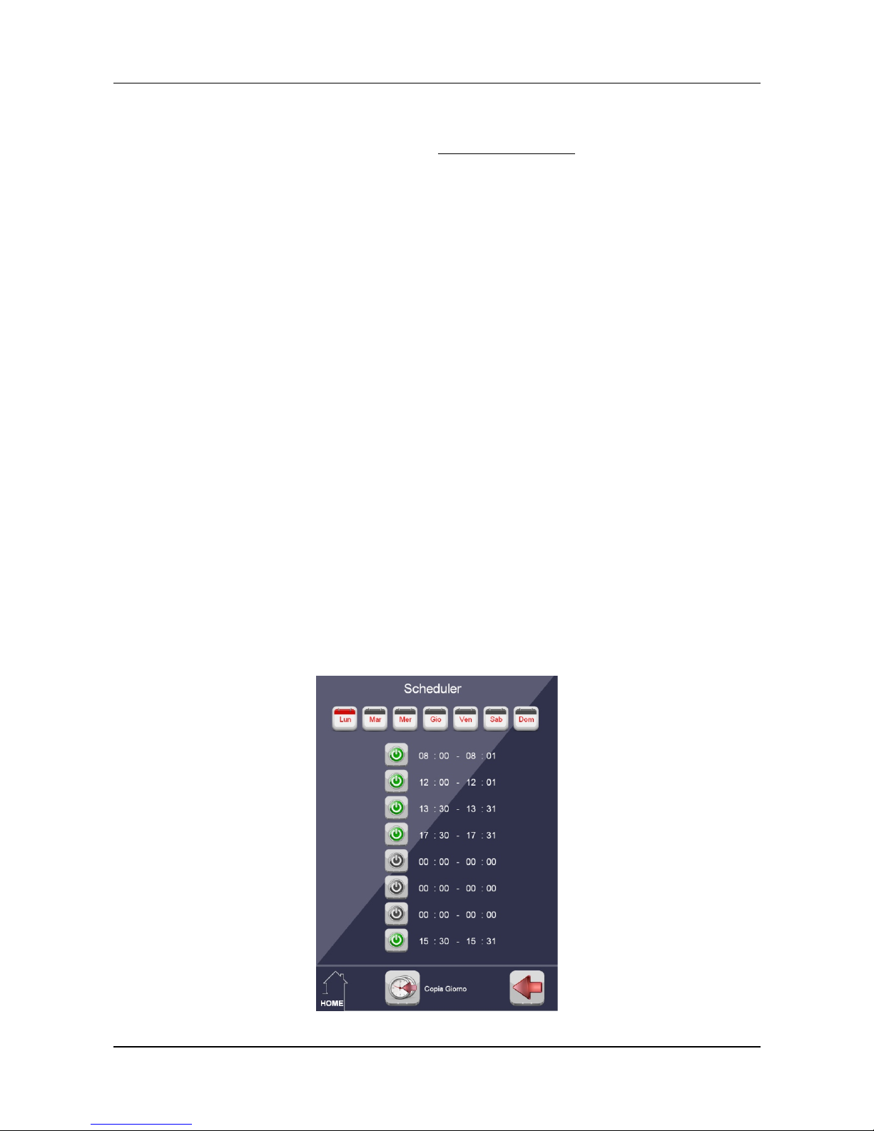
The Scheduler integrated in MCP 4 allows the control of 16 different points (“zones”) each one with 8 time
slots (8 ON-OFF intervals) for each day of the week. The resolution of the Scheduler is 1 minute.
The Scheduler will be activated by the following directive:
SCHEDULER n ( Vx )
where:
n is the Scheduler number (“zone”) and it must be in the range 1 to 16
Vx is the controlled virtual point
I the points to be controlled are more than one, more directives must be added as in the following example.
SCHEDULER 1 ( V100 )
SCHEDULER 2 ( V101 )
SCHEDULER 3 ( V102 )
Unlike CLOCK equation which will be described later, where the specified times are set in the user program
and then the change these ones requires reprogramming of MCP 4, the Scheduler here described allows
easy setting from any supervision program or through the WEB server (optional) integrated in MCP 4. For
details on entering and modification of schedules, refer to the specific documentation.
The following figure shows an example of a page that can be developed for the management of the
Scheduler.
Page 16 of 87 Rel.: 1.2 October 2018 DUEMMEGI s.r.l. - Via Longhena, 4 – 20139 MILANO
Tel. 02/57300377 - Fax 02/55213686 – www.duemmegi.it

DUEMMEGI
MCP 4 – User's manual
Contatto
2.2- Event triggered Equations
2.2.1- Logic equations
Operators: & (AND), | (OR), ! (NOT), ^ (XOR)
(XOR is evaluated by the compiler as follows: A ^ B = !A & B | A & !B)
O10.3 = I1.1
O2.5 = (I1.1 | I1.2)
V6 = (I4.3 | I8.2) & V4
O1.6 = V100 & I1.7
O1.6 = !I1.3 & I1.7
O1.1 = I2.1 & (I4.3 | I2.4)
O8.1 = V7 ^ I43.2
2.2.2- SET – RESET equations
Operators:
S SET on the edge
SP SET priority on the edge
SL SET on the level
SPL SET priority and on the level
R RESET on the edge
RP RESET priority on the edge
RL RESET on the level
RPL RESET priority on the level
O1.1 = SI1.1 & RI1.2 Set/Reset edge triggered.
O1.1 = SI1.1 & RI1.2 Set/Reset edge triggered
O1.1 = SI1.1 & RLI1.2 Reset on the level: out is locked OFF if I1.2 is activated.
O1.1 = SPLI1.1 & RLI1.2 Set/Reset on the level, but out is locked ON if I1.1 is activated (since
it is specified to be a priority command).
O1.5 = I2.3 & RI2.1 & SI4.6 I2.3 is a consent.
O1.1 = (SI1.1 | SI1.2) & RI1.3 Parenthesis use: out goes ON activating I1.1 or I1.2.
O1.1 = SI1.1 & RI1.2 & RI1.3 Out goes OFF activating I1.2 or I1.3.
O1.1 = SLI1.1 & SLI1.2 & RI1.3 Out goes ON activating BOTH I1.1 and I1.2
DUEMMEGI s.r.l. - Via Longhena, 4 – 20139 MILANO
Tel. 02/57300377 - Fax 02/55213686 – www.duemmegi.it
Rel.: 1.2 October 2018 Page 17 of 87

Contatto
MCP 4 – User's manual
DUEMMEGI
2.2.3- TOGGLE equations
Operators:
T TOGGLE on the edge
S SET on the edge
SP SET priority on the edge
SL SET on the level
SPL SET priority and on the level
R RESET on the edge
RP RESET priority on the edge
RL RESET on the level
RPL RESET priority on the level
Terms must be linked by OR operators; no “free” input can be used.
O1.1 = TI6.1 | TV6 Out toggles at every OFF-ON variation of I6.1 or V6.
O1.1 = T!I6.1 Out toggles at the variation ON-OFF of the input.
V100 = TV1 | SV2 | RV3 Set and Reset on the edge.
V100 = TV1 | SV2 | RLV3 Out is locked OFF until V3 is activated (being on the level) .
O1.1 = TI1.1 | TI1.2 | SI1.3 | SI1.4 | RI1.5 | RI1.6 More command inputs.
2.2.4- COUNTER Equations
Counter equation controls a digital output as function of the comparison between the counter value and a
threshold. 1024 counters can be defined. Each counter can be controlled by real or virtual inputs, each one
with its own specific function:
1. one or more inputs for forward or backward counting (S(k))
2. one or more inputs for the zeroing or to load the counter with a defined value (P(z), PP(z),
PL(z), PPL(z) )
3. one or more inputs to stop the counting (H, HP )
The counter, depending on the variations at its inputs, will be updated and then compared to the threshold
value, in order to control the output. Allowed operators are:
< lower than
<= lower or equal to
== equal to
!= not equal to
> greater than
>= greater or equal to
Control operators:
S(k) Sum k to counter on the edge (k range: -32768 to 32767)
P(z) Preset counter to z on the edge (z range: 0 to 65535)
PP(z) Priority Preset counter to z on the edge (z range: 0 to 65535)
PL(z) Preset counter to z on the level (z range: 0 to 65535)
PPL(z) Priority Preset counter to z on the level (z range: 0 to 65535)
H Lock the counter to the current value on the level (Halt)
HP Priority Lock the counter to the current value on the level (Halt)
Page 18 of 87 Rel.: 1.2 October 2018 DUEMMEGI s.r.l. - Via Longhena, 4 – 20139 MILANO
Tel. 02/57300377 - Fax 02/55213686 – www.duemmegi.it

DUEMMEGI
MCP 4 – User's manual
Contatto
All counters of MCP4 are in 16-bit format, thus the content of each counter is in the range 0 to 65535.
For the counter function, the following options can be also specified:
➢ AUTORESET/AUTORELOAD
➢ MIN
➢ MAX
➢ Cn,R copy the counter value to a register (with same identifier)
➢ Variable parameters
The syntax allowing to specify these options is the following (Vx may be any allowed point):
Vx = Cy,R > 30, AR, MIN, MAX .........
where:
• R means that the counter value is continuously copied in a register (with the same identifier)
• AR is the (optional) value for the autoreset and the autoreload, in order to make possible the
automatic zeroing and the automatic loading of the counter: when the forward counting exceeds the
value AR, then the counter wil be automatically zeroed, while when the backward counting decrease
below the value 0, then the counter will be automatically reloaded with the value AR. This value can
be also the content of a register (see the examples in the following). Note: if the autoreset/autoreload
value has not been specified, then the counting will be stopped to 0 (when down counting) and at the
maximum allowed value (when up counting), thus avoiding the underflow or the overflow of the counter.
• MIN is the minimum value that can be assumed by the counter; the default value is 0
• MAX is the maximum value that can be assumed by the counter; the default value is 65535
The values for the threshold, autoreset, minimum, maximum, step and preset can be also the content of
registers (see the examples in the following).
If one of the options AR, MIN and MAX has been omitted, the default value will be assumed. The described
options must be however separated by commas as in the following examples.
Examples:
V1 = C0>300 S(2)I1.1 & S(-1)I1.2 Up counting step 2, Down counting step 1, V1 goes
ON when counter is greater than 300.
V1 = C0>30,50 S(1)I1.1 & S(-1)I1.2 Autoreset/Autoreload: when counter exceeds 50, it is
reset to zero; when the counter goes below zero, it is
reloaded to 50.
V1 = C0>30,,5,50 S(1)I1.1 & S(-1)I1.2 MIN and MAX: the up counting is stopped to 50 and
the down counting is stopped to 5.
V1 = C0>3,5,1 S(1)I1.1 & S(-1)I1.2 Autoreset/Autoreload and MIN: when counter
exceeds 5, it is reloaded to 1; when the counter goes
below 1, it is reloaded to 5.
V15 = C10,R > 100 S(1)I1.1 & S(-1)I1.2 \ Copy Counter to Reg: the value of C10 is copied
& PL(0)I1.3 to register R10.
V10 = C1 > R0,R1,R2,R3 S(R4)I1.1 \ Variable parameters.
& P(R4)I1.3
DUEMMEGI s.r.l. - Via Longhena, 4 – 20139 MILANO
Tel. 02/57300377 - Fax 02/55213686 – www.duemmegi.it
Rel.: 1.2 October 2018 Page 19 of 87

Contatto
MCP 4 – User's manual
DUEMMEGI
2.2.5- THRESHOLD Equations
Threshold equation controls a digital output as function of the comparison between an analog value (input
module or register) and a Threshold and an Hysteresis. Allowed comparison operators:
< lower than
<= lower or equal to
== equal to
!= not equal to
> greater than
>= greater or equal to
Options:
➢ Hysteresis
➢ Variable parameters
The Hysteresis has a different meaning depending on the comparison operator:
< OUT goes ON when AI<T and OUT goes OFF when AI>=(T + H)
<= OUT goes ON when AI<=T and OUT goes OFF when AI>(T + H)
== OUT goes ON when AI==T and OUT goes OFF when AI>(T + H) or when AI<(T - H)
!= OUT goes OFF when AI==T and OUT goes ON when AI>(T + H) or when AI<(T - H). This
behavior is complementary to the previous case
> OUT goes ON when AI>T and OUT goes OFF when AI<=(T - H)
>= OUT goes ON when AI>=T and OUT goes OFF when AI<(T - H)
Threshold and Hysteresis must be in the range 0 to 65535. Other allowable operators: AND (&) and OR (|).
Examples:
O1.1 = AI1 >= 240,2
V2 = AI1 == 40 | AI2 == 30
V2 = AI1 == 40,5
O1.4 = AI1 < 128 & AI1 > 30
O1.5 = AI1 < 600 & R50 >= 30
O1.1 = AI1 > R51,R52 & AI1 < 1000,5
2.2.6- TIMER Equations
Timer equation controls a digital output as function of two delay times. 512 timers can be defined. The timer
resolution is 0.1s and time range is 0 to 6553.5s (1h:49’). The times specified in the timer equation are
intended in second multiplied by 10 (Te=100 means 10 seconds).
The input starting the timer is the “trigger” input and it always works on the edge.
Keyword:
TIMER Standard timer
TIMERP Non re-triggerable Pulse timer (monostable)
TIMERPR Re-triggerable Pulse timer (monostable)
E4ended control operators:
H Lock the timer to the current value on the level (Halt)
Z Zero, force the expiring of the current timer value (if running) on the edge
ZL Zero, force the expiring of the current timer value on the level
Page 20 of 87 Rel.: 1.2 October 2018 DUEMMEGI s.r.l. - Via Longhena, 4 – 20139 MILANO
Tel. 02/57300377 - Fax 02/55213686 – www.duemmegi.it

DUEMMEGI
MCP 4 – User's manual
Contatto
Note: if the Zero on the level command is activated, the trigger status is transferred to the output without
delays. The priority sequence for the timer controls is fixed to Halt, Zero and Trigger.
Options:
➢ Variable parameters
O1.1 = TIMER(I2.5, 30, 10) 3s delay from I2.5 activation to the out activation; 1s delay from I2.5
deactivation to out deactivation.
V23 = TIMER(!I1.1, 0, 23) Out is complemented in respect to the trigger input.
O1.1 = TIMER(I2.5 & HI5.1 & ZI5.2, 90, 50) Trigger, Halt and Zero: I5.1 halts the timer,
I5.2 forces the expiring of the currently
running time; if the timer is in stand-by, Halt
and Zero controls have not any effect.
O1.1 = TIMERP(I1.1, 0, 20) 2s pulse at the activation of the trigger input; no action at the
deactivation of the input.
O1.1 = TIMERP(I1.1, 10, 20) 2s pulse delayed 1s from the activation of the trigger input.
O1.1 = TIMERPR(I1.1, 0, 20) Re-triggerable 2s pulse (computed from last activation of the trigger.
O1.1 = TIMERPR(I1.1, 10, 20) Re-triggerable 2s pulse delayed 1s from the first activation of the
trigger input.
O1.1 = TIMER(I1.1, R47, R48) Variable parameters.
2.2.7- Equations for mathematical and logic calculation
Allowed MATH and LOGIC operators:
MATH LOGIC
Symbol Function Symbol Function
+
Sum
&
AND
-
Subtract
|
OR
*
Multiply
^
XOR
/
divide
P()
Preset
Preset options:
P Preset on the edge: load the specified value at the edge of the control input
PL Preset on the level: load the specified value and lock the result to that value
Notes:
• there is no priority between logical and algebraic operators: the equation is calculated
sequentially from left to right; brackets are not allowed
• the Preset on level always takes priority over calculation of the equation and over Preset on edge
• if in the same equation more Presets on level are activated, priority is given to the leftmost one
• when a Preset on level is activated, the result of the equation is frozen to the value determined by
that same Preset; if instead the Preset is on the edge, the result of the equation will be the value
established by that same Preset until no further changes occur to other terms inside the equation
• each terms involved in a calculation equation is 16-bit number; the partial results are evaluated as
32-bit number, but the final result will be truncated to the less significant 16 bits
DUEMMEGI s.r.l. - Via Longhena, 4 – 20139 MILANO
Tel. 02/57300377 - Fax 02/55213686 – www.duemmegi.it
Rel.: 1.2 October 2018 Page 21 of 87

Contatto
MCP 4 – User's manual
DUEMMEGI
Examples:
AO1:1 = AI1:4 + 128
R12 = AI1:4 + 12 & 0x00F0 + R1 & P(30)I23.5
R54 = R52 / R53 + R54 * 2
A mathematical equation can also be made by one or more Preset terms only; this is useful to load a value in
a register or to an output at the activation (or de-activation) of a control input:
R0 = P(1527)V1
R1 = P(0x1AB7)I1.8 & P(0)!I1.8
AO23:2 = P(12000)V148 & P(0b11000011)I12.1 & PL(0)!I32.7
Exclusively for real outputs (thus registers, counters etc. are excluded), it is possible to define multiple
Presets activated by the same digital point; in this case, at the activation of the common digital point, the
values defined by the Preset will be sent sequentially to the output, in the order in which they have been
entered into the equation (from left to right). The following examples show some possibilities.
When V1 goes ON, the values 10, 20 and 30 will be sequentially sent to the output:
AO1:1 = P(10)V1 & P(20)V1 & P(30)V1
When V1 goes ON, the values 10 and 20 and 30 will be sequentially sent to the output; when V2 goes ON,
the values 30 and 40 will be sequentially sent to the output:
AO1:1 = PL(10)V1 & P(20)V1 & P(30)V2 & P(40)V2
When V1 goes ON, only the value 20 will be sent to the output, because it is a Preset on level:
AO1:1 = P(10)V1 & PL(20)V1 & P(30)V1
When V1 goes ON, only the value 10 will be sent to the output, because it is the Preset on level placed on the
leftmost side in the equation:
AO1:1 = PL(10)V1 & PL(20)V1 & P(30)V1
2.2.8- Equations for binary code generation
Keyword:
SENDn(Tr) Send the specified code to output n at the activation of the related input (or de-
activation if complemented), with refresh time Tr seconds (when more inputs are
activated)
SENDRn(Tr) Send the specified code to register Rn at the activation of the related input (or de-
activation if complemented), with refresh time Tr seconds (when more inputs are
activated)
The sent code (Bx) must be in the range 0 to 255. If the refresh time has been omitted, then it will be set to 2
seconds. The refresh time must be in the range 1 to 254 seconds; it is possible to disable the refresh by
specifying the value 255. In this case the sent code will be always that related to last change of one among
the inputs listed in the SEND block.
The input points causing the sending of the related binary code may be real and virtual ones; they can be also
complemented.
Page 22 of 87 Rel.: 1.2 October 2018 DUEMMEGI s.r.l. - Via Longhena, 4 – 20139 MILANO
Tel. 02/57300377 - Fax 02/55213686 – www.duemmegi.it

DUEMMEGI
MCP 4 – User's manual
Contatto
Up to 16 independent SEND block can be defined.
SEND4 (5) = ( I1.1, B001, \
I1.2, B002, \
V354, B003, \
!I4.7, B006, \
!V450, B129 \
)
SENDR123(2) = ( I5.8, B001, \
V100, B002, \
V101, B003, \
!V470, B004, \
!V480, B005 \
)
Note: commas are mandatory symbols.
2.2.9- Equations for recording status changes (EVENT)
This function allows to store, in chronological order, the status change of the real input points and of the
virtual points that have been specified in the EVENT block. Each status change will be stored together to:
Day/Month Hour:Minutes:Seconds
The EVENT function allows to specify if MCP 4 has to store the OFF-ON or the ON-OFF status change or
both. The EVENT function will also automatically register the so called “system events”, that are the failure
and the restoring of any module and of the bus; the doubled address events will be automatically registered
too. Up to 2048 events can be stored in the RAM.
The section of the RAM where these events are stored has the battery back-up feature, therefore the events
remain stored even if the main supply voltage fails (at least until the battery does not reach the minimum
retaining voltage of the memory).
Keyword:
EVENT Create the event list (fixed buffer): when the buffer is full, it does not accept any other
event (in this way the list contains the first 2048 events from the last cleaning of the
buffer)
EVENTC Create the event list (circular buffer): when the buffer is full, it overwrites the old
events (in this way the list contains the last 2048 events)
No more than 1 EVENT block can be declared in the same MCP 4 module. If the buffer is full (case EVENT)
or the old events have been overwritten (case EVENTC), then the virtual point V2008 will be activated to
report this occurrence.
EVENTC = ( \ Inizio blocco, il buffer è circolare
V1, ON, \ Evento 1, alla transizione 0-1 di V1
V2, OFF, \ Evento 2, alla transizione 1-0 di V2
I3.7, ON, OFF \ Evento 3, ad entrambe le transizioni 0-1 e 1-0 di I3.7
)
Note: commas are mandatory symbols.
DUEMMEGI s.r.l. - Via Longhena, 4 – 20139 MILANO
Tel. 02/57300377 - Fax 02/55213686 – www.duemmegi.it
Rel.: 1.2 October 2018 Page 23 of 87

Contatto
MCP 4 – User's manual
DUEMMEGI
2.2.10- Equations for recording value changes (LOG)
This function allows to store , in chronological order, the change of the value returned by input modules or
registers that have been specified in the LOG block. Change in the value means exclusively a change from
any value to another one, on condition that the new value is not zero, unless this has not been expressly
declared; in other words, any change from zero to any other value, or from any value to another one (but not
zero) will be registered, while a change from any value to zero will not be registered, unless not expressly
declared in the LOG block. For instance:
1. a change from 0 to 287 will be registered
2. a change from 287 to 584 will be registered
3. a change from 584 to 321 will be registered
4. a change from 321 to 0 will NOT be registered, unless not expressly declared
This function is useful, for instance, to record the codes of the transponders controlling an access to a
building. In the LOG block can be specified both real input addresses (specifying the channel if any) and
registers. Each value change will be stored together to:
Day/Month Hours:Minutes:Seconds
Up to 1024 16-bit values (or codes) can be stored in the RAM of MCP 4; since the section of the RAM where
these events are recorded has the battery back-up feature, the values remain stored even if the main supply
voltage fails (at least until the battery does not reach the minimum retaining voltage of the memory).
Keyword:
LOG Create the value list (fixed buffer): when the buffer is full, it does not accept any other
value (in this way the list contains the first 1024 value from the last cleaning of the
buffer)
LOGC Create the value list (circular buffer): when the buffer is full, it overwrites the old
values (in this way the list contains the last 1024 values)
Option:
ZERO Declare that, for the related input or register, also changes from any value to zero
has to be recorded
No more than 1 LOG block can be declared in the same MCP 4 module. If the buffer is full (case LOG) or
the old events have been overwritten (case LOGC), then the virtual point V2009 will be activated to report this
occurrence.
LOGC = ( \ Block start, the buffer is circular type
AI47:2, \ changes of input AI47 channel 2, changes to zero excluded
AI3, ZERO, \ changes of input AI3 channel 1, changes to zero included
R230, ZERO, \ changes of register R230, changes to zero included
R321 \ changes of register R321, changes to zero excluded
)
Note: commas are mandatory symbols.
Page 24 of 87 Rel.: 1.2 October 2018 DUEMMEGI s.r.l. - Via Longhena, 4 – 20139 MILANO
Tel. 02/57300377 - Fax 02/55213686 – www.duemmegi.it

DUEMMEGI
MCP 4 – User's manual
Contatto
2.2.11- Management of the external counter modules (ModCNT)
The counter module (code number ModCNT) is an external module (connected to the Contatto bus) which
counts the pulses applied to its inputs; it stores the total amount of the counting in its non volatile memory.
The management of this module by MCP 4 needs a special function, specified by an equation very similar to
that one for the management of the internal counters. Each ModCNT counter module features 4 counting
channels, thus the equation must specify the channel to be managed.
MCP 4, through a threshold equation, can continuously read the content of each external counter and it can
compare it to the threshold value; the result of the comparison controls a digital (real or virtual) output.
Allowed comparison operators are:
< lower than
<= lower or equal to
== equal to
!= not equal to
> greater than
>= greater or equal to
It is also possible to specify a real or virtual input which, when activated, reset to the value 0 the counter
specified in the equation; this is however an optional input and must be linked by the operator “&”.
The threshold value also can be the content of a register.
Examples:
O1.1 = AI10:2 >= 100 & ZI1.1 The output is controlled by channel 2 of ModCNT module, addressed
10; the output will be activated if the counting is greater or equal to
100. The input I1.1, when activated, will reset the counter to 0.
V10 = AI10:4 > R0 The virtual point V10 will be activated if the counting of the channel 4
of ModCNT module addressed 10 is greate than the content of
register R0.
2.2.12- Management of DALI module (ModDALI)
This equation allows to simplify the management of ModDALI module, especially in systems where the
automatic brightness regulation has to be implemented. The syntax of DALI equation is the following:
AOUT = DALI (Code, AIN(offset))
where:
AOUT output (address:channel of ModDALI to be managed) or register where the result of equation
will be sent
Code DALI command type (broadcast, single ballast or group)
AIN analog input whose value must be transferred (typically address:channel of ModLC sensor)
or register containing the value to be transferred
offset value or register containing a value in the range -100 to 100; this value will be algebraically
added to AIN; this is useful, for instance, when the brightness regulation from a unique
sensor must be differentiated between rows of lamps depending on the distance from
windows
At every change of one of the AIN values inside the DALI block, the related value will be transferred to the
specified channel of ModDALI module and, by this one, to all ballasts, or to a single ballast, or to a group
depending on the value of Code.
DUEMMEGI s.r.l. - Via Longhena, 4 – 20139 MILANO
Tel. 02/57300377 - Fax 02/55213686 – www.duemmegi.it
Rel.: 1.2 October 2018 Page 25 of 87

Contatto
MCP 4 – User's manual
DUEMMEGI
The allowed Code, therefore the DALI destinations, are the following:
Code = 0xXX direct declaration of the code in hexadecimal format; for instance 0x81 means,
according to DALI specifications, that AIN must be sent to group 1
Code = B1..B32 equivalent to 0x01..0x20, for commands to single ballast
Code = G1..G16 equivalent to 0x81..0x90, for group commands
Code = ALL equivalent to 0x00, for broadcast commands
Example:
AO1:2 = DALI ( G1, AI44:2, \ // Send AI44:2 to Group 1
G2, R1, \ // Send R1 to Group 2
G3, R1(10), \ // Send R1 incremented by 10 to Group 3
G4, R1(-10), \ // Send R1 decremented by 10 to Group 4
B1, AI45:2, \ // Send AI45:2 to Ballast 1
B2, R5, \ // Send R5 to Ballast 2
B3, R6(10), \ // Send R6 incremented by 10 to Ballast 3
B4, R6(-10), \ // Send R6 decremented by 10 to Ballast 4
ALL, R100 \ // Send R100 to all Ballasts (broadcast)
)
These commands will be sent, in this example, to channel 2 only of DALI module addressed 1 (AO1:2).
Note: commas are mandatory symbols.
Page 26 of 87 Rel.: 1.2 October 2018 DUEMMEGI s.r.l. - Via Longhena, 4 – 20139 MILANO
Tel. 02/57300377 - Fax 02/55213686 – www.duemmegi.it

DUEMMEGI
MCP 4 – User's manual
Contatto
2.3- Time triggered Equations
2.3.1- Scheduler Equations
Scheduler equation controls a digital output as function of specified ON/OFF time or date. MCP 4 includes a
timekeeper with back-up battery to avoid the date and time loss when disconnecting the main power supply.
The transition from standard to daylight saving time is made automatically by MCP 4, therefore no
intervention of the user is required.
The times specified in the scheduler equations can be daily or weekly times; the scheduled dates can be
yearly or absolute dates.
Keyword:
CLOCK controls the output as function of current time
DATE controls the output as function of the current date
Options:
Variable daily scheduling times specified in a register (Rx) or in a Word (@WORD x)
containing a number in the range 0 to 1439, corresponding to the number of minutes of the day
starting from 0:00 (1439 = 23:59); the formula giving the number related to time hh:mm is the
following: (hh x 60) + mm
Variable weekly scheduling times specified in a register (Rx) or in a Word (@WORD x)
containing a number in the range 0 to 10079, corresponding to the number of minutes of the
week starting from 0:00 of Monday (10079 = 23:59 of Sunday); the formula giving the number
related to time DW:hh:mm, assuming for the days of the week (DW) MON=0…SUN=6, is the
following: (DW x 1440) + (hh x 60) + mm
Variable yearly dates specified in a register (Rx) or in a Word (@WORD x) containing a number
in the range 1 to 372 corresponding to the day of the year starting from January 1 (372 =
December 31); the formula giving the number related to the day DD (131) of month MM (112)
is the following: (MM –1) x 31 + DD
Variable absolute dates specified in a register (Rx) or in a Word (@WORD x) containing a
number in the range 1 to 37200 corresponding to the day of the century starting from January 1
00 (37200 = December 31, 99); the formula giving the number related to the day DD (1 31) of
month MM (112) of year YY (099) is the following: (372 x YY) + (MM –1) x 31 + DD
Notes:
the argument x of the notation @WORD x may be in the range 0 to 65535; this is true, unless otherwise
specified, for the CLOCK and DATE equations only
the timing 24:00 is not allowed; use instead the timing 00:00, taking attention that it is the morning of
the specified day.
O1.1 = CLOCK(8:15, 17:30) Out is ON everyday from 8:15 to 17:30 (daily
scheduling).
V3 = CLOCK(MON:8:00, FRI:20:00) Out is on from Monday 8:00 to Friday 20:00 (weekly
scheduling).
O3.2 = DATE(31/07, 02/09) Out is ON from July 31 to September 9 (yearly
scheduling).
O3.2 = DATE(31/07/05, 02/09/05) Out is ON from July 31,2005 to September 9, 2005
(absolute scheduling).
V4 = CLOCK(TUE:8:00, TUE:12:00) | \ Out is ON the Tuesday 8:00 to 12:00 and it is also
CLOCK(THU:14:30, SAT:00:00) ON from Thursday 14:30 to Saturday 0:00.
DUEMMEGI s.r.l. - Via Longhena, 4 – 20139 MILANO
Tel. 02/57300377 - Fax 02/55213686 – www.duemmegi.it
Rel.: 1.2 October 2018 Page 27 of 87
 Loading...