

Page 1
INSTALLATION AND USER INSTRUCTIONS
BUILT-IN MIXED HOB, INDUCTION DOMINO HOB
Page 2

2
WARNING:
The appliance and its accessible parts become hot
during use.
Care should be taken to avoid touching heating elements.
Children less than 8 years of age shall be kept away unless
continuously supervised.
This appliance can be used by children aged from 8 years and above
and persons with reduced physical, sensory or mental capabilities or
lack of experience and knowledge if they have been given
supervision or instruction concerning use of the appliance in a safe
way and understand the hazards involved.
Children shall not play with the appliance.
Cleaning and user maintenance shall not be made by children without
supervision.
WARNING:
Unattended cooking on a hob with fat or oil can be
dangerous and may result in fire. NEVER try to extinguish a fire with
water, but switch off the appliance and then cover flame e.g. with a lid
or a fire blanket.
WARNING: Danger of fire: do not store items on the cooking
surfaces.
WARNING: If the surface is cracked, switch of the appliance to
avoid the possibility of electric shock.
WARNING: do not use a steam cleaning unit of: stoves, hobs
and ovens.
WARNING: the hob is not designed to work with an external timer,
or with a remote control system.
WARNING: Use only hob guards designed by the manufacturer of
the cooking appliance or indicated by the manufacturer of the
appliance in the instructions for use as suitable or hob guards
incorporated in the appliance. The use of inappropriate guards
can cause accidents.
WARNING:The cooking process has to be supervised. A short
term cooking process has to be supervised continuously.
Page 3
3
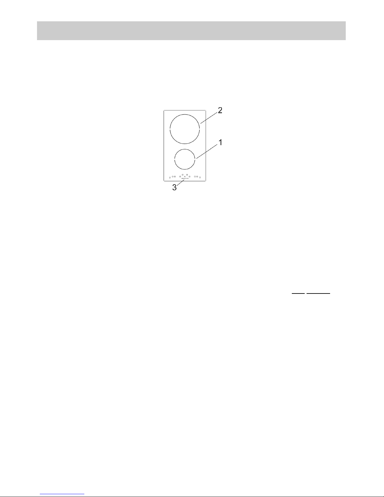
DESCRIPTION
The appliance has 2 cooking areas with different sizes and different power levels. The induction
elements are of the magnetic induction type, which come on after selecting the heating element, and the
heat can be regulated using the controls on the front panel, from a minimum of 1 to a maximum of 9
(depending on the models).
The cooking areas have concentric discs with the following diameters.
COOKING AREA
TYPE: PCZ VTCI
with booster
1 Induction element Ø 14,5 cm 1200 W 1600 W
2 Induction element Ø 21,0 cm 1500 W 2000 W
3 Touch control
Page 4
4
DESCRIPTION
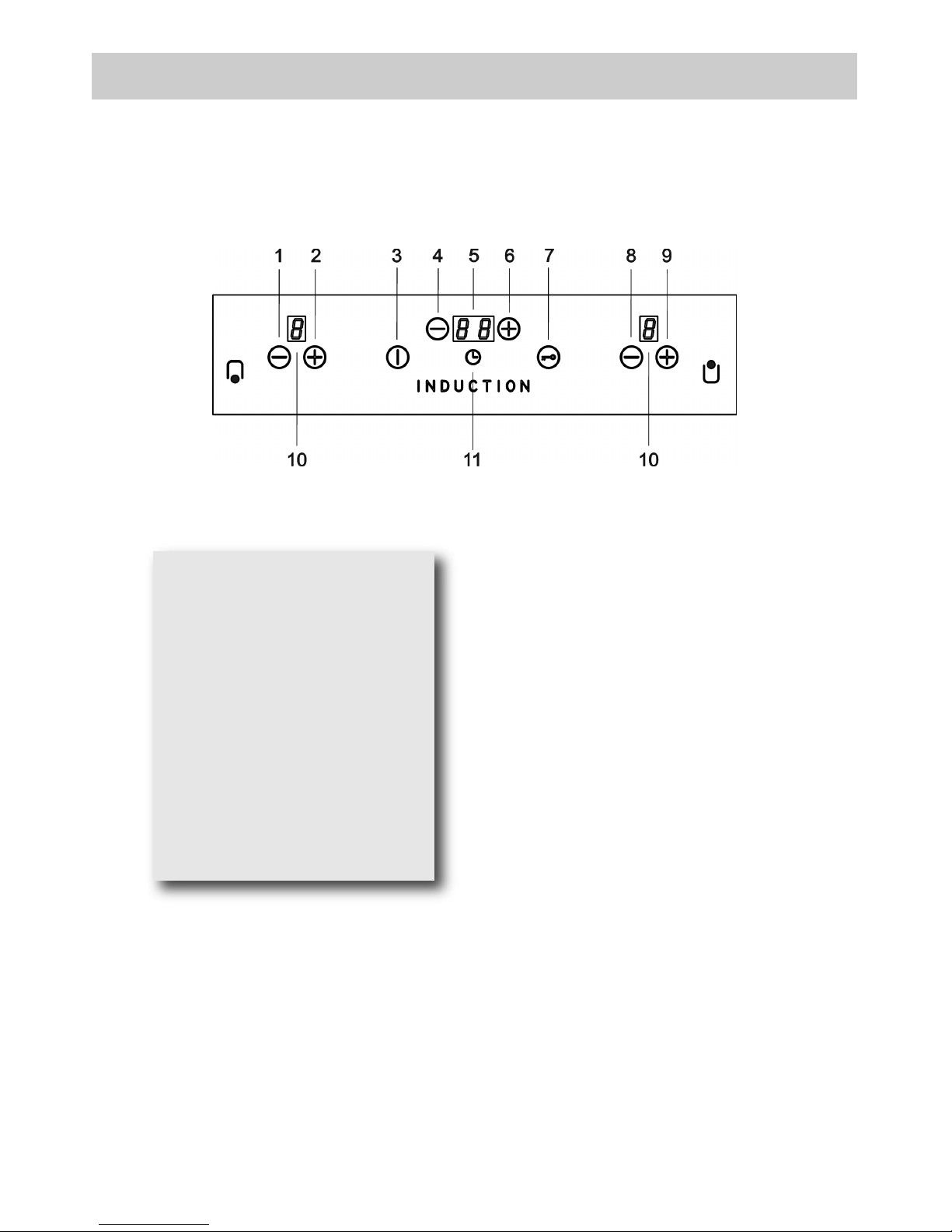
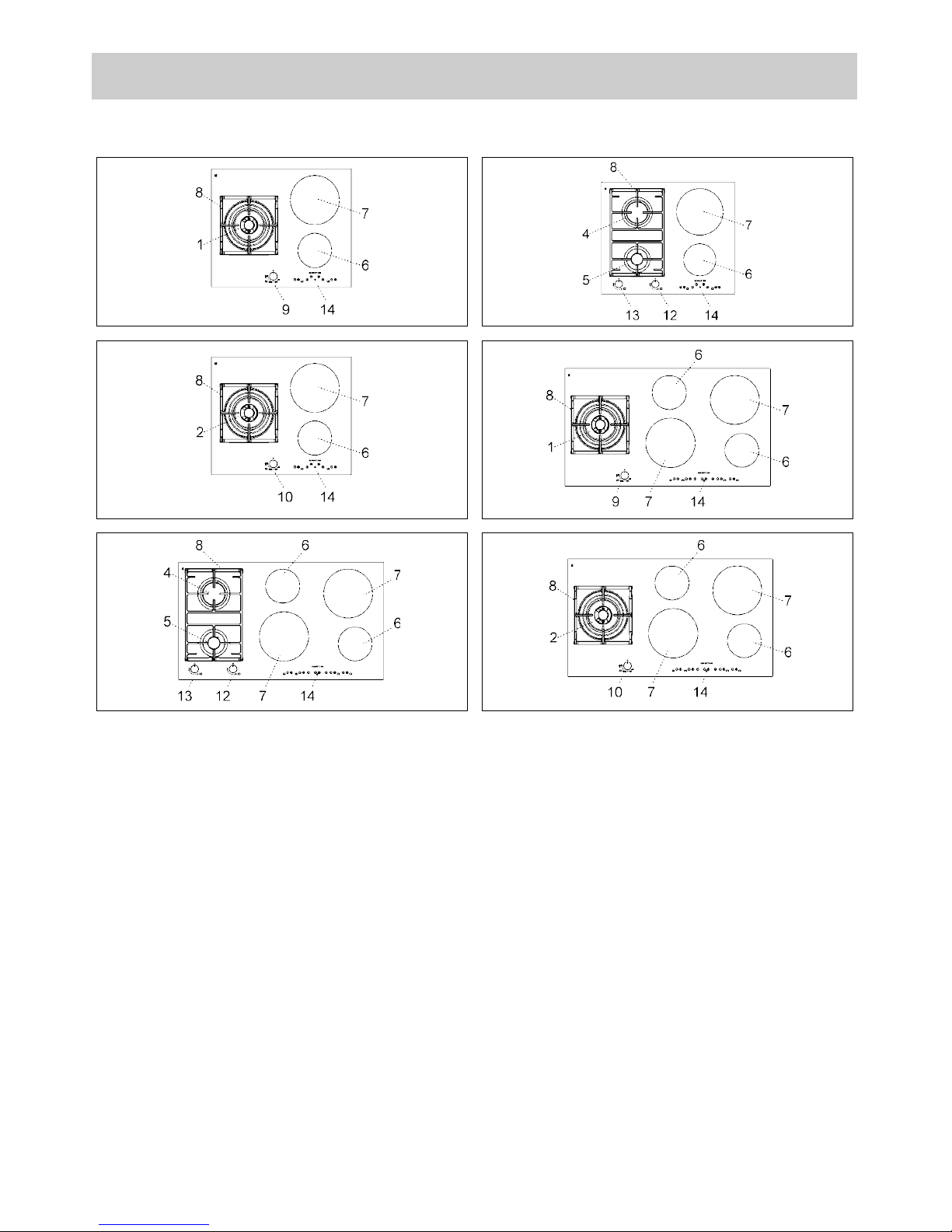
DESCRIPTION OF FRONT PANEL CONTROLS
2 INDUCTION ELEMENT
1 - Induction element 1 – button
2 - Induction element 1 + button
3 - ON/OFF button
4 - TIMER programming – button
5 - Clock levels display
6 - TIMER programming + button
7 - Safety lock button
8 - Induction element 2 – button
9 - Induction element 2 + button
10 - Display cooking levels (0 - 9)
11 - Symbol TIMER
Page 5
5
INITIAL LIGHT CONDITIONS
When power is initially applied to the Cooktop, the touch control conducts a calibration process for the
touch keys, which requires a low level of ambient light in the area of the touch keys.
If during this calibration process excessive ambient lighting is detected the User Interface displays “FL”
(Infrared Ambient Light Error) and the control calibration process is suspended. In order to rectify the
process any lighting that could effect the calibration process should be switched off (e.g. halogen cooker
hood lighting). The error will disappear when satisfactory ambient lighting is detected and the touch
control calibration procedure will now complete satisfactorily.
Notes:
● the “FL” error can only be generated within approx 3s of initial power being applied to the cooktop.
● We recommend that the user switches off all cooker hood lighting and lighting directed towards the
cooktop when power is initially applied to the cooktop.
● After the touch control has conducted its initial calibration process (approx 3s), any cooker hood or
other lighting can be switched on as normal and will not affect the operation of the touch control.
INSTRUCTIONS FOR THE USER
Every time a symbol is pressed it is confirmed by a beep. The functions of hobs that use this type of
technology are activated by gently pressing the symbols printed on the surface. When connecting to the
electricity supply for the first time, an operating check will be run and all the warning lights will light up for
a few seconds.
Model: 30 cm.
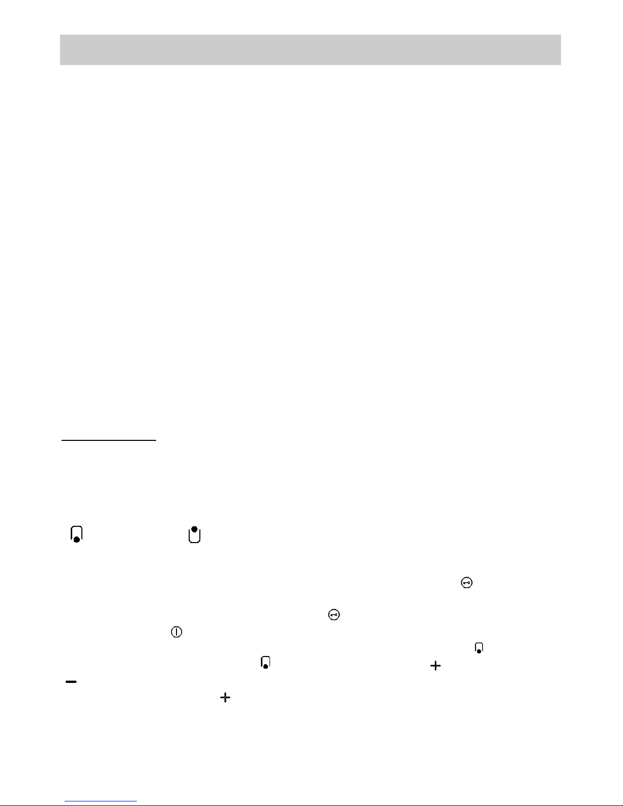
ARRANGEMENT OF THE HEATING ELEMENTS
FRONT BACK
Every time the hob is reconnected to the electricity supply, the control panel lock is active and the
relative led in on.
After removing the control panel lock (by pressing the symbol for 1 second), switch on the hob by
pressing the symbol for a few seconds. If no function is activated within 10 seconds, the hob will
switch off automatically. The associated heating element is indicated next to every control area.
Identify the heating element to activate ( ) and then activate it using the and
symbol, regulating the level of cooking required on a scale o 1 to 9. With the heating element set
on 9 it is possible, pressing the key, to activate the “fast boil” function (booster), indicated with a
P
on the display. The heating element will work at maximum power for 10 minutes, after which it will return
to level 9, issuing a beep.
DESCRIPTION
Page 6
6
TIMER
There is a timer for setting cooking times from 1 to 99 minutes (symbol ).
After activating the cooking area required, selecting it on the display, activate the timer by pressing the
or symbol above the symbol. Then return to the heating element to be programmed by pressing its
or symbol. Return to the timer and set the programming time using the or symbol. The
programmed heating element is highlighted by the corresponding led above the cooking level indicator.
The timer will start 5 seconds after the last symbol has been pressed and the heating element will operate
until the number on the display reaches 0. The heating element will then switch off automatically. When the
time ends a sequence of beeps will be repeated at 3 second intervals for 1 minute.
During timed cooking it is possible to change the operating power and the cooking time. Every time the
or symbols of the cooking area are pressed, the heating element operating power is increased or
reduced. To change the amount of time remaining, it is necessary to press the or symbol of the
heating element until the led position in the cooking area switches on. Then the operating time can be
changed using the and symbols of the timer.
KEY LOCK FUNCTION
Lock Function (
): this function prevents the hob from being accidentally switched on (child safety lock).
To activate it, the sensor must be pressed for about three seconds (the warning light comes on). It is
not possible to make the heating areas work if is active. If the heating elements are still working, it is
possible to switch them off while is active. This function is deactivated by pressing the sensor for
two seconds, for all the configurations.
RESIDUAL HEAT
Every plate has a device which indicates the presence of residual heat. On the display, after switching off
any plate, an may appear. This signal indicates that the cooking area is still very hot. It is possibile
to start cooking food again even when the is visibile, by reactivating the heating element required.
SWITCHING OFF THE PLATES
The plates switch off when the relative operating power display indicates 0. The plate will be
automatically deactivated five seconds after the 0 appears on the display. If the plates are hot, the
indicating the presence of residual heat will appear. To immediately switch off an element, simply touch
the and keys together, or the
key until 0 appears on the display.
SWITCHING OFF THE HOB
The hob is switched off by pressing the symbol for one second, even if the plates are operating; all
the plates will be deactivated and the hob will switch off completely. If the plates are hot, the
indicating the presence of residual heat will appear after switching off. There is a heat protection system
installed inside the hob. If the temperature exceeds 95 °C, the hob switches off automatically. This is to
prevent excessive temperature from damaging the internal components.
DESCRIPTION
Page 7
7
WARNINGS:
see figure 1 for correct use, and remember:
- only connect the power supply after placing
the pan on the cooking area.
- Use pans with a thick, flat bottom.
- Dry the bottom of the pan before placing it on
the cooking area.
- Do not drag pans across the glass hob as
this may damage the surface.
- Never leave the appliance unattended while
the cooking areas are in use and ensure that
children are kept at a safe distance. Pay
close attention to children because they are
unlikely to see the “H” indication of residual
heat. After use, the cooking areas remain
very hot for a while, even when they have
been switched off. Do not allow children to
rest their hands on them. After using the hob,
always make sure that the controls are in the
“zero” position (off). Make sure that pan
handles are correctly positioned towards the
inside and supervise the cooking of foods in
oil and fat, as these are highly flammable.
- After use, the cooking areas remain hot for a
long time; do not rest your hands or other
objects on them to avoid the risk of burns,
until the “H” indicating the presence of
residual heat has switched off.
- Should a crack appear on the surface of the
glass, disconnect the appliance from the
electricity supply immediately.
- Do not rest sheets of aluminium or plastic
containers on the hot surface.
- Do not use the hob as a work surface.
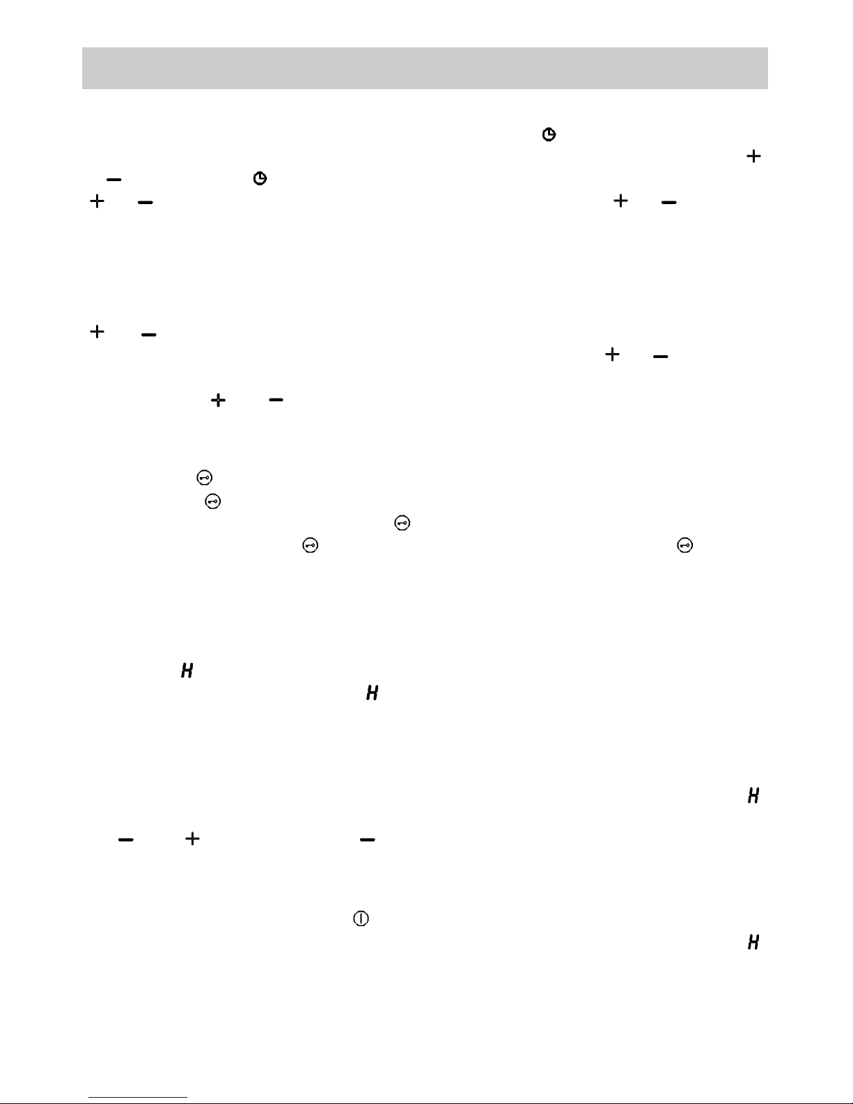
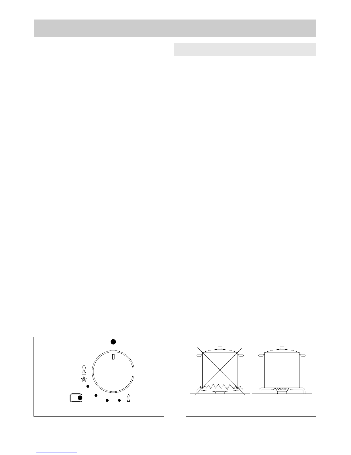
- The pans must be properly centred on the
heating elements (see fig. 2). If the pan is not
properly centred over the corresponding
printed area or is removed without switching
the element off, a sensor automatically
switches off the hob after a few seconds and
the symbol appears on the display
indicating the absence of the pan. If the pan
is not returned to or correctly positioned on
the cooking area within 1 minute, the hob
resets and if no control is pressed, it
switches off after 20 seconds.
- If the power level does not change during a
set period of time, the corresponding heating
element switches off automatically. The
maximum time that a heating element can
remain switched on depends on the cooking
level selected (see table below: HOB
AUTOMATIC SWITCH-OFF). glass, terracotta,
aluminium without a special finish on the
bottom, copper or non-magnetic steel pans
are not suitable for use with the induction
hob. We recommend using thick-bottomed
pans so that the heat is distributed properly
and the food cooks more evenly. Always use
pans bearing the logo indicating that they are
suitable for use with an induction hob, with
the word INDUCTION. Use a magnet to check
that your pans are compatible: if the magnet
is attracted to the pan, it is compatible for
use.
See the following table for the pan diameters
to use:
Pans with smaller diameters risk non being
detected and therefore not activating the
inductor.
USE
Power level selected
Corresponding time
(in hours)
1 10
2 10
3 10
4 10
5 10
6 10
7 10
8 10
9 3
HOB AUTOMATIC SWITCH-OFF
Coil Ø Minimun pan Ø
14,5 cm 9,0 cm
21,0 cm 13,0 cm
FIG. 2
Page 8
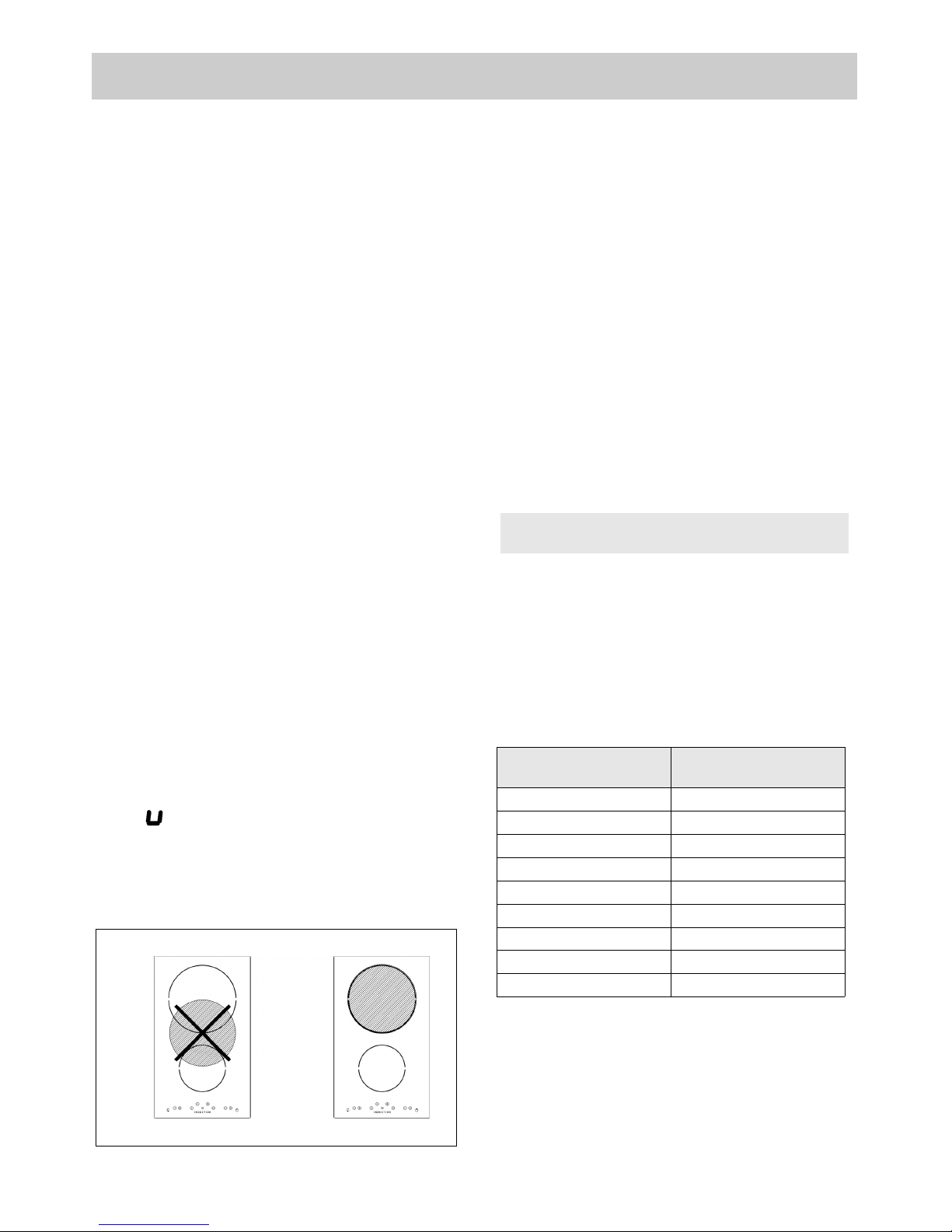
8
TYPE: PCZVB
1 Double crown burner of 5000 W
2 Triple crown burner of 4000 W
4 Rapid burner of 2800 W
5 Auxiliary burner of 1000 W
6 Electric heating element induction Ø 14,5 cm
of 1200 W (booster function 1600 W)
7 Electric heating element induction Ø 21,0 cm
of 1500 W (booster function 2000 W)
8 Pan support
9 Burner n° 1 control knob
10 Burner n° 2 control knob
12 Burner n° 4 control knob
13 Burner n° 5 control knob
14 Touch control
Attention: this appliance has been manufactured for domestic use only and it employment by
private person.
The appliance has 2/4 cooking areas with different sizes and different power levels. The heating
elements are of the magnetic induction type, which come on after selecting the heating element, and the
heat can be regulated using the controls on the front panel, from a minimum of 1 to a maximum of 9
(depending on the models). There is also a fast boiling function (booster) indicated by the letter Pon the
display. The cooking areas have concentric discs with the following diameters.
DESCRIPTION
Page 9
9
DESCRIPTION OF FRONT PANEL CONTROLS
DESCRIPTION
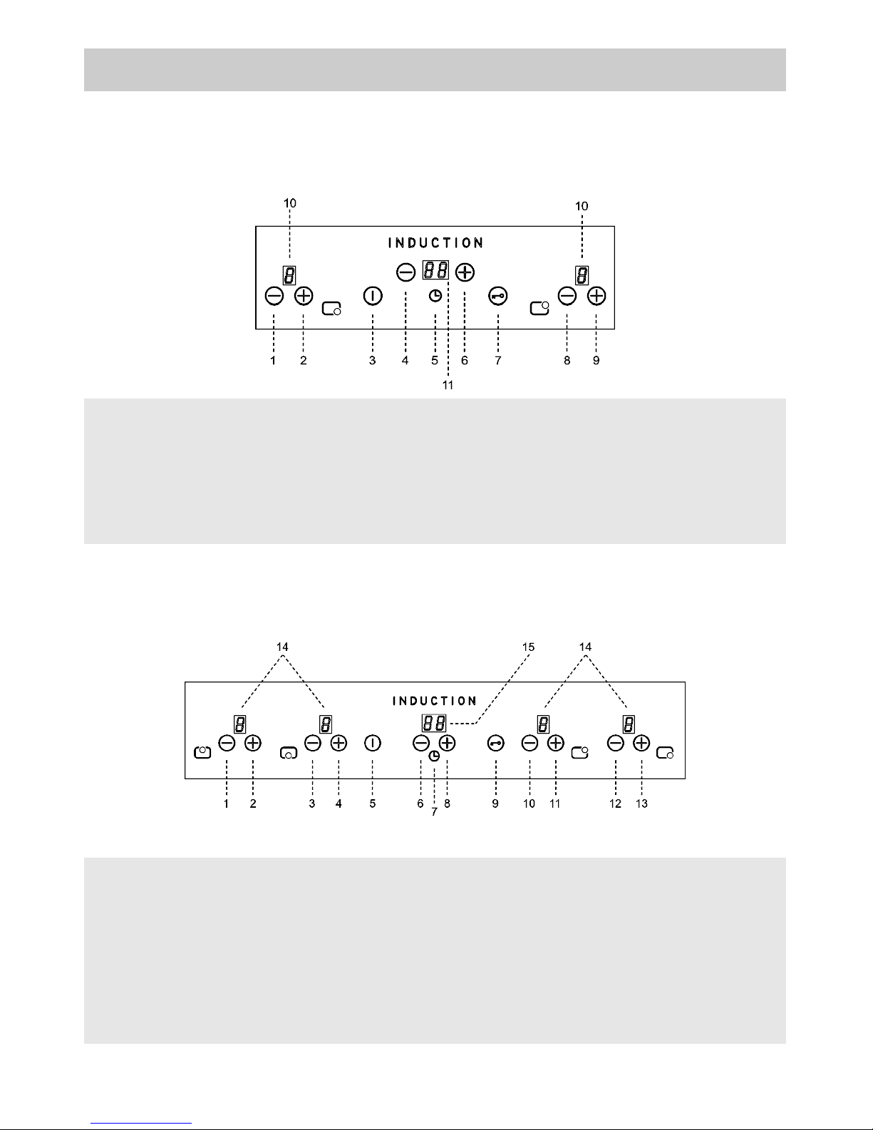
DESCRIPTION OF FRONT PANEL CONTROLS
1 - Induction element 6 – button
2 - Induction element 6 + button
3 - ON/OFF button
4 - TIMER programming – button
5 - Symbol TIMER
6 - TIMER programming + button
7 - Safety lock button
8 - Induction element 7 – button
9 - Induction element 7 + button
10 - Display cooking levels (0 - 9)
11 - Display clock
1 - Induction element 7 – button (left)
2 - Induction element 7 + button (left)
3 - Induction element 6 – button (left)
4 - Induction element 6 + button (left)
5 - ON/OFF button
6 - TIMER programming – button
7 - Symbol TIMER
8 - TIMER programming + button
9 - Safety lock button
10 - Induction element 7 – button (right)
11 - Induction element 7 + button (right)
12 - Induction element 6 – button (right)
13 - Induction element 6 + button (right)
14 - Display cooking levels (0 - 9)
15 - Display clock
60 cm.
90 cm.
Page 10
10
USE
FIG. 2
1) TRADITIONAL BURNERS
A diagram is screen-printed above each knob on
the front panel. This diagram indicates to which
burner the knob in question corresponds. After
having opened the gas mains or gas bottle tap,
light the burners as described below:
- manual ignition
Push and turn the knob corresponding to the
required burner in an anticlockwise direction until it
reaches the full on position (large flame fig. 1),
then place a lighted match near the burner.
- Automatic electrical ignition
Push and turn the knob corresponding to the
required burner in an anticlockwise direction until it
reaches the full on position (large flame fig. 1),
then depress the knob.
- Lighting burners equipped with flame failure
device
The knobs of burners equipped with flame failure
device must be turned in an anticlockwise direction
until they reach the full on position (large flame
fig. 1) and come to a stop. Now depress the knob
in question and repeat the previously indicated
operations.
Keep the knob depressed for about 10 seconds
once the burner has ignited.
Note: you are advise not to try and light a
burner if the flame divider (Burner Cap) is not
correctly place.
In the event of the Burner flames being
accidentally extinguished, turn off the burner
control and do not attempt to re-ignite the
burner for a least 1 minute.
HOW TO USE THE BURNERS
Bear in mind the following indications in order to
achieve maximum efficiency with the least possible
gas consumption:
- use adequate pans for each burner (consult the
following table and fig. 2).
- When the pan comes to the boil, set the knob to
the reduced rate position (small flame fig. 1).
- Always place a lid on the pans.
- Use only pan with a flat bottom and in thick
metal.
WARNINGS:
- burners with flame failure device may only be
ignited when the relative knob has been set to
the Full on position (large flame fig. 1).
- Matches can be used to ignite the burners in
a blackout.
- Never leave the appliance unattended when
the burners are being used. Make sure there
are no children in the near v i c i n i t y.
Particularly make sure that the pan handles
are correctly positioned and keep a check on
foods requiring oil and grease to cook since
these products can easily catch f i r e .
- Never use aerosols near the appliance when it
is operating.
- Containers wider than the unit are not
recommended.
Closed position
Full on position
Reduced rate
position
Burners Power W Ø Pan cm
Double crown 5000
24 ÷ 26
Triple crown 4000
24 ÷ 26
Rapid 2800
20 ÷ 22
Auxiliary 1000
10 ÷ 14
FIG. 1
Page 11
11
USE
During, and immediately after operation,
some parts of the cook top are very hot:
avoid touching them.
FIG. 3 FIG. 4 FIG. 5
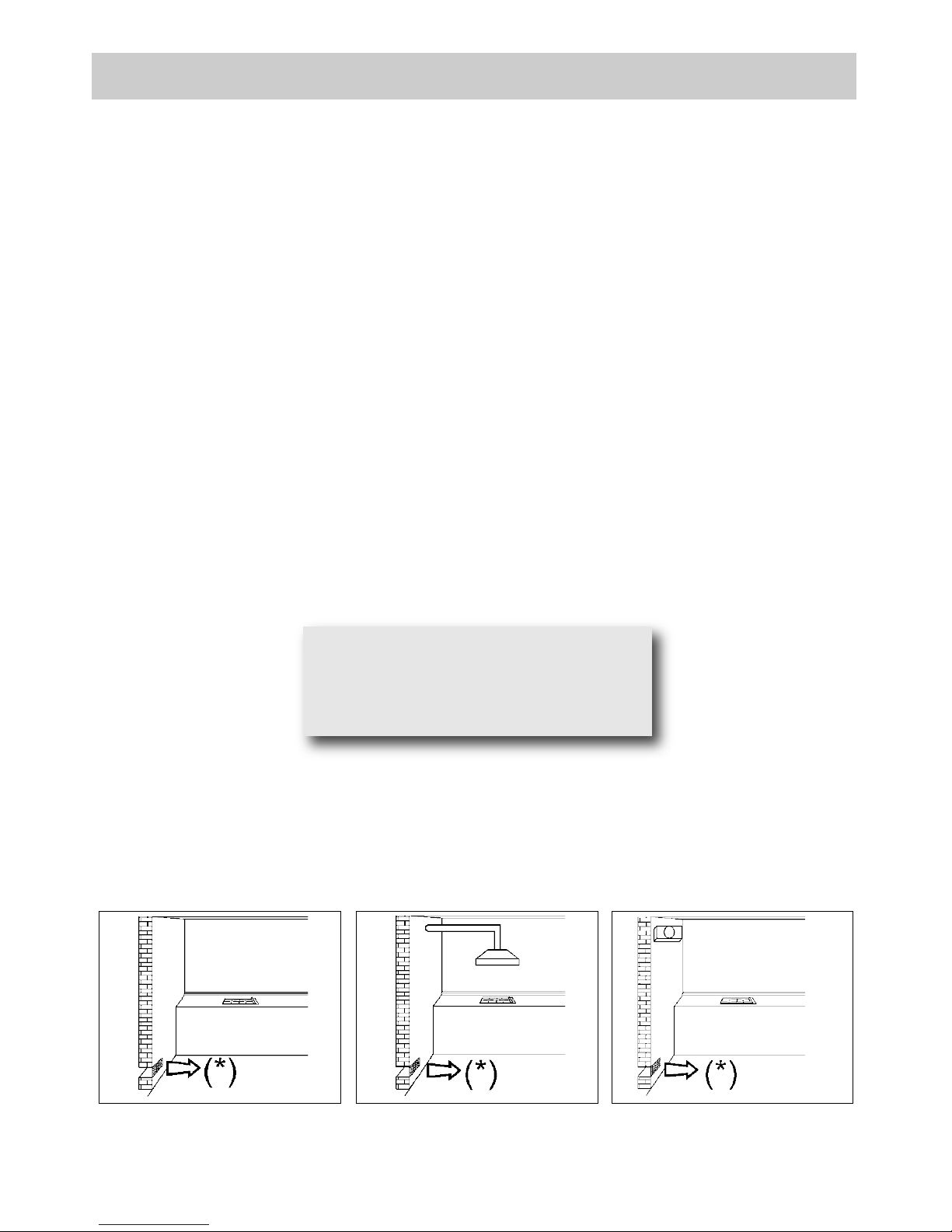
(*) AIR INLET: SEE INSTALLATION CHAPTER (PARAGRAPHS 7 AND 8)
WARNINGS AND ADVICE FOR THE USER:
- use of a gas cooking appliance produces heat and moisture in the room in which it is installed.
The room must therefore be well ventilated by keeping the natural air vents clear (fig. 3) and by
activating the mechanical aeration device (suction hood or electric fan fig. 4 and fig. 5).
- Intensive and lengthy use of the appliance may require additional ventilation. This can be
achieved by opening a window or by increasing the power of the mechanical exhausting system
if installed.
- After using the cook top, make sure that the knob is in the closed position and close the main
tap of the gas supply or gas cylinder.
- If the gas taps are not operating correctly, call the Customer Care Department.
Page 12

2) INSTRUCTIONS FOR THE USER
Every time a symbol is pressed it is confirmed by a beep. The functions of hobs that use this type of
technology are activated by gently pressing the symbols printed on the surface. When connecting to the
electricity supply for the first time, an operating check will be run and all the warning lights will light up for
a few seconds.
USE
WARNING FOR USE:
►
The appliance is built to perform the following function: cooking and heating food.
Every other use must be considered improper.
►
Never use this appliance to heat the environment.
►
Do not attempt to change the technical characteristics of the product because it
can be dangerous.
►
If you should not to use this appliance any more (or replace an old model), before disposing
of it, make it inoperative in conformity with current law on the protection of health and the
prevention of environmental pollution by making its dangerous parts harmless, especially
for children who might play on an abandoned appliance.
►
Do not touch the appliance with wet or damp hands or feet.
►
Do not use the appliance barefoot.
►
The manufacturer will not be liable for any damage resulting from improper, incorrect or
unreasonable use.
►
If the ceramic hob is not cleaned immediately there is a risk of forming encrustations which
are impossible to remove after the hob has cooled or has been reheated several times.
►
Do not use gloves when programming the hob. Press with clean fingers and touch the
glass gently.
►
Do not leave any type of metallic object, such as forks, knives, spoons or lids on the hob, as
they might accumulate heat, posing a hazard.
►
The hob operates in compliance with the current legislation on electromagnetic fields and
interference deriving from their use. The appliance in fully compliant with the legal
requirements in force. Wearers of pacemakers or other similar devices must ensure that
these appliances have been built or operate in compliance with the above legislation.
►
Wearers of pacemakers or other similar devices must be certain that the operation of these
devices is not disturbed by the magnetic field generated by the hob, which has a frequency
between 20 KHz and 50 KHz.
12
Page 13

13
USE
ARRANGEMENT OF THE HEATING ELEMENTS
Model: 60 cm.
FRONT BACK
Every time the hob is reconnected to the electricity supply, the control panel lock is active and the
relative led in on.
After removing the control panel lock (by pressing the symbol for 1 second), switch on the hob by
pressing the key for a few seconds.
If no function is activated within 10 seconds, the hob will switch off automatically.
The associated heating element is indicated next to every control area. Identify the heating element to
activate and then activate it using the and keys, regulating the level of cooking required on a
scale o 1 to 9. With the heating element set on 9 it is possible, pressing the , key, to activate the “fast
boil” function (booster), indicated with a P on the display. The heating element will work at maximum power
for 10 minutes, after which it will return to level 9, issuing a beep.
TIMER
There is a timer for setting cooking times from 1 to 99 minutes (symbol ).
After activating the cooking area required, selecting it on the display, activate the timer by pressing the
or symbol above the symbol. Then return to the heating element to be programmed by
pressing its or symbol. Return to the timer and set the programming time using the or
symbol. The programmed heating element is highlighted by the corresponding led above the cooking level
indicator.
The timer will start 5 seconds after the last symbol has been pressed and the heating element will operate
until the number on the display reaches 0. The heating element will then switch off automatically. When the
time ends a sequence of beeps will be repeated at 3 second intervals for 1 minute.
During timed cooking it is possible to change the operating power and the cooking time. Every time the
or symbols of the cooking area are pressed, the heating element operating power is increased or
reduced. To change the amount of time remaining, it is necessary to press the or symbol of the
heating element until the led position in the cooking area switches on. Then the operating time can be
changed using the and symbols of the timer.
Page 14

USE
KEY LOCK FUNCTION
Lock Function (
): this function prevents the hob from being accidentally switched on (child safety
lock). To activate it, the sensor must be pressed for about three seconds (the warning light comes
on). It is not possible to make the heating areas work if is active. If the heating elements are still
working, it is possible to switch them off while is active. This function is deactivated by pressing the
sensor for two seconds, for all the configurations.
RESIDUAL HEAT
Every plate has a device which indicates the presence of residual heat. On the display, after switching off
any plate, an may appear. This signal indicates that the cooking area is still very hot. It is possibile
to start cooking food again even when the is visibile, by reactivating the heating element required.
SWITCHING OFF THE PLATES
The plates switch off when the relative operating power display indicates 0. The plate will be
automatically deactivated five seconds after the 0 appears on the display. If the plates are hot, the
indicating the presence of residual heat will appear. To immediately switch off an element, simply touch
the and keys together, or the key until 0 appears on the display.
SWITCHING OFF THE HOB
The hob is switched off by pressing the symbol for one second, even if the plates are operating; all
the plates will be deactivated and the hob will switch off completely. If the plates are hot, the
indicating the presence of residual heat will appear after switching off. There is a heat protection system
installed inside the hob. If the temperature exceeds 95 °C, the hob switches off automatically. This is to
prevent excessive temperature from damaging the internal components.
Model: 90 cm.
FRONT LEFT BACK LEFT BACK CENTRAL
FRONT RIGHT BACK RIGHT FRONT CENTRAL
Every time the hob is reconnected to the electricity supply, the control panel lock is active and the
relative led in on.
After removing the control panel lock (by pressing the symbol for 1 second), switch on the hob by
pressing the key for a few seconds. If no function is activated within 10 seconds, the hob will switch
off automatically. The associated heating element is indicated next to every control area. Identify
the heating element to activate ( ) and then activate it using the and keys, regulating the
level of cooking required on a scale o 1 to 9. With the heating element set on 9 it is possible, pressing the
key, to activate the “fast boil” function (booster), indicated with a
P
on the display. The heating
element will work at maximum power for 10 minutes, after which it will return to level 9, issuing a beep.
14
Page 15

15
USE
TIMER
There is a timer for setting cooking times from 1 to 99 minutes (symbol ).
After activating the cooking area required, selecting it on the display, activate the timer by pressing the
or symbol above the symbol. Then return to the heating element to be programmed by pressing its
or symbol. Return to the timer and set the programming time using the or symbol. The
programmed heating element is highlighted by the corresponding led above the cooking level indicator.
The timer will start 5 seconds after the last symbol has been pressed and the heating element will operate
until the number on the display reaches 0. The heating element will then switch off automatically. When the
time ends a sequence of beeps will be repeated at 3 second intervals for 1 minute.
During timed cooking it is possible to change the operating power and the cooking time. Every time the
or symbols of the cooking area are pressed, the heating element operating power is increased or
reduced. To change the amount of time remaining, it is necessary to press the or symbol of the
heating element until the led position in the cooking area switches on. Then the operating time can be
changed using the and symbols of the timer.
KEY LOCK FUNCTION
Lock Function (
): this function prevents the hob from being accidentally switched on (child safety
lock). To activate it, the sensor must be pressed for about three seconds (the warning light comes
on). It is not possible to make the heating areas work if is active. If the heating elements are still
working, it is possible to switch them off while is active. This function is deactivated by pressing the
sensor for two seconds, for all the configurations.
RESIDUAL HEAT
Every plate has a device which indicates the presence of residual heat. On the display, after switching off
any plate, an may appear. This signal indicates that the cooking area is still very hot. It is possibile
to start cooking food again even when the is visibile, by reactivating the heating element required.
SWITCHING OFF THE PLATES
The plates switch off when the relative operating power display indicates 0. The plate will be
automatically deactivated five seconds after the 0 appears on the display. If the plates are hot, the
indicating the presence of residual heat will appear. To immediately switch off an element, simply touch
the and keys together, or the key until 0 appears on the display.
SWITCHING OFF THE HOB
The hob is switched off by pressing the symbol for one second, even if the plates are operating; all
the plates will be deactivated and the hob will switch off completely. If the plates are hot, the
indicating the presence of residual heat will appear after switching off. There is a heat protection system
installed inside the hob. If the temperature exceeds 95 °C, the hob switches off automatically. This is to
prevent excessive temperature from damaging the internal components.
Page 16

USE
FIG. 6
Power and dimensions
of the cooking area
Area
no.
Diameter
in cm
Power
W
Touch control
positions
Cooking
operations
with booster
6 14,5 1200 1600 1
To melt butter, chocolate,
etc.; to heat small
amounts of liquid.
7 21,0 1500 2000 1 - 3
To heat larger amonts of
liquid; to prepare creams
and sauces reuiring
lenththy cooking times.
4 - 8
To thaw frozen foods and
prepare stews, heat to
boiling point or simmer.
5 - 9
To cook foods that have
to be boiled, for delicate
roastmeats and fish.
9 - P
To boil large amounts of
liquid, to fry..
3) GUIDE TO COOKING
The table below indicates the power values that can be set and the type of food to prepare is shown next
to each one. The values can change according to the amount of food and consumer preference.
TABLE
In order to cook with the heating element
efficiently using the least amount of energy,
use: thick, flat-bottomed pots of a width
suited to that of the heating element (see
picture). Cook with the lid on to also save
energy. Turn down the heating element
when it reaches boiling point.
16
Page 17

17
USE
WARNINGS:
see figure 7 for correct use, and remember:
- only connect the power supply after placing
the pan on the cooking area.
- Use pans with a thick, flat bottom.
- Dry the bottom of the pan before placing it on
the cooking area.
- Do not drag pans across the glass hob as
this may damage the surface.
- Never leave the appliance unattended while
the cooking areas are in use and ensure that
children are kept at a safe distance. Pay
close attention to children because they are
unlikely to see the “H” indication of residual
heat. After use, the cooking areas remain
very hot for a while, even when they have
been switched off. Do not allow children to
rest their hands on them. After using the hob,
always make sure that the controls are in the
“zero” position (off). Make sure that pan
handles are correctly positioned towards the
inside and supervise the cooking of foods in
oil and fat, as these are highly flammable.
- After use, the cooking areas remain hot for a
long time; do not rest your hands or other
objects on them to avoid the risk of burns,
until the “H” indicating the presence of
residual heat has switched off.
- Should a crack appear on the surface of the
glass, disconnect the appliance from the
electricity supply immediately.
- Do not rest sheets of aluminium or plastic
containers on the hot surface.
- Do not use the hob as a work surface.
- The pans must be properly centred on the
heating elements (see fig. 7). If the pan is not
properly centred over the corresponding
printed area or is removed without switching
the element off, a sensor automatically
switches off the hob after a few seconds and
the symbol appears on the display
indicating the absence of the pan. If the pan
is not returned to or correctly positioned on
the cooking area within 1 minute, the hob
resets and if no control is pressed, it
switches off after 20 seconds.
- If the power level does not change during a
set period of time, the corresponding heating
element switches off automatically. The
maximum time that a heating element can
remain switched on depends on the cooking
level selected (see table below: HOB
AUTOMATIC SWITCH-OFF).
- Glass, earthenware, aluminium without a
special finish on the bottom, copper or nonmagnetic steel pans are not suitable for use
with the induction hob.
- We recommend using thick-bottomed pans
so that the heat is distributed properly and
the food cooks more evenly.
- Always use pans bearing the logo indicating
that they are suitable for use with an
induction hob, with the word INDUCTION.
Use a magnet to check that your pans are
compatible: if the magnet is attracted to the
pan, it is compatible for use.
See the following table for the pan diameters
to use:
Pans with smaller diameters risk non being
detected and therefore not activating the
inductor.
Power level
selected
Corresponding time
(in hours)
1 10
2 10
3 10
4 10
5 10
6 10
7 10
8 10
9 3
HOB AUTOMATIC SWITCH-OFF
Cooking zone Ø Minimun pan Ø
14,5 cm 9,0 cm
21,0 cm 13,0 cm
FIG. 7
Page 18

IMPORTANT:
always disconnect the appliance from the gas
and electricity mains before carrying out any
cleaning operation.
4) CERAMIC WORKTOP
It is very important to clean the hob every time you
use it, while the glass is still warm.
Do not clean using abrasive metal scourers,
powder abrasives or corrosive sprays.
Periodically wash the hot plate, the pan support,
the enamelled burner caps “A”, “B” and “C” and
the burner heads "T" (see fig. 8/A - 8/B) with
lukewarm soapy water.
They should also be cleaned plugs "AC" and flame
detection "TC" (see fig. 8/B).
Clean them gently with a small nylon brush as
shown (see fig. 8) and allow to dry fully.
Do not wash in the dishwasher.
Following this, all parts should be thoroughly
rinsed and dried. Never wash them while they are
still warm and never use abrasive powders.
WARNINGS:
comply with the following instructions, before
remounting the parts:
●check that burner head slots “T” (fig. 8/A)
have not become clogged by foreign bodies.
●Check that enamelled burner cap “A”, “B”
and “C” (fig. 8/A - 8/B) have correctly
positioned on the burner head. It must be
steady.
●The exact position of the pan support is
established by the rounded corners, which
should be set towards the side edge of the
cooktop.
●Do not force the taps if they are difficult open
or close. Contact the technical assistance
service for repairs.
●Don’t use steam jets for the equipment
cleaning.
FIG. 8
FIG. 8/B
FIG. 8/A
CLEANING
18
Note:
continuous use could cause the burners to
change colour due to the high temperature.
Page 19

19
MEASUREMENTS TO OBSERVE (in mm)
A B C D E F G
30 cm
282 482 59 59 100 min. 30 - max 50 min. 120 mm
60 cm
560 490 55 55 60 min. 30 - max 50 min. 120 mm
90 cm
860 490 55 55 60 min. 30 - max 50 min. 120 mm
INSTALLATION
FIG. 9/A
ADDITIONAL WARNINGS
Depending on the degree of dirt, we recommend:
- for light stains, a damp sponge is sufficient.
- Tough, encrusted dirt is easily eliminated using a
scraper (see fig. 9). Use the scraper carefully
to avoid damaging the hob.
- Traces of liquid spilled from pans can be
eliminated with vinegar or lemon juice.
- Never allow sugar or sugary foods to fall on
the hob while cooking.
Should this occur, switch off the hob and clean
it immediately with hot water, using a scraper
on hot spills.
- As time goes by metallic reflections, colouring or
scratches may appear due to poor cleaning and
the incorrect movement of pans. Scratches
are hard to eliminate but do not affect the correct
operation of your hob.
- After a period of time may appear metal reflex
and scratches (fig. 9/A) due to the wrong
cleaning and the wrong use of the pots. The
scratches are difficultly removable, but they do
not compromise the good working of the hob.
- Do not use jets of steam to clean the
appliance.
INDUCTION COOKING
The induction cooking principle is based on a
magnetic phenomenon. When we put a pan on the
heating element, we switch on the hob and
activate the element, the electronic circuit inside
the appliance generates an induced current which
heats the bottom of the pan and the food
(see fig. 10).
FIG. 10
CAUTION:
do not place the glass directly on the unit.
The bottom of the hob must rest on the unit.
FIG. 9
Page 20

FIG. 13
FIG. 11
FIG. 12
Safety distances furniture
INSTALLATION
TECHNICAL INFORMATION
FOR FITTERS
The installation, transformation and
maintenance operations listed in this section
must be carried out exclusively by qualified
personnel.
The appliance must be correctly installed in
conformity with current law and the
manufacturer's instructions.
Incorrect installation may cause injury to
people or animals, or damage to items, for
which the manufacturer cannot be held
responsible.
Throughout the life of the system, the devices
for the safety and automatic regulation of the
appliances must only be modified by the
manufacturer or the duly authorised supplier.
5) INSERTION
After removing the outer and inner packing of the
various mobile parts, ensure that the hob is
undamaged. If you are in any doubt, do not use the
appliance and connect qualified personnel.
The packing elements (cardboard, bags,
polystyrene, nails...) must not be left within the
reach of children as they are potential sources
of danger.
It is necessary to make a hole in the kitchen unit to
house the hob, observing the measurements in
mm indicated in fig. 12 and ensuring that the
critical distances between the hob, the lateral
walls, the rear wall and the upper surface are
respected (see fig. 11, 12 and 13).
The prospective walls (left or right) that exceed the
working table in height must be at a minimum
distance from the cutting as mentionned both in the
columns “E” of the scheme.
The appliance belongs to class 3 and is
therefore subject to all the provisions
established by the provisions governing such
appliances.
IMPORTANT:
a perfect installation, adjustment or
transformation of the cook top to use other
gases requires a QUALIFIED INSTALLER: a
failure to follow this rule will void the
warranty.
20
Page 21

21
INSTALLATION
6) FITTING THE HOB
The hob is equipped with a special seal to
avoid any infiltration of liquid into the unit. To
apply this seal correctly, please follow the
instructions given below carefully:
- remove all the mobile parts of the hob.
- Turn the hob upside down and place the
adhesive putty “E” (fig. 14) under the edge of the
hob so that perfectly matches the outer perimeter
edge of the glass. The ends of the strips must
match without overlapping.
- Stick the putty to the glass evenly and securely,
using your fingers to press it into place.
- For the gas: fix the hob with the proper hooks
“S” and fit the prominent part into the porthole
“H” on the bottom; turn the screw “F” until the
hook “S” stick on the top (fig. 15).
- For the induction: position the hob in the hole in
the unit and fasten it in place using the
appropriate screws “F” of the fastening hooks “G”
(see fig. 15/A).
- In order to avoid accidental contact with the
surface of the box of the overheated hob during
use, it is necessary to install a wooden divider at
a minimum distance of 120 mm from the top,
fastening it in place with screws (fig. 12).
FIG. 14
CAUTION:
In case of hotplate glass breakage:
●shut immediately off all burners and any
electrical heating element and isolate the
appliance from the power supply;
●do not touch the appliance surface;
●do not use the appliance.
Page 22

INSTALLATION
Positioning hooks
60 cm.
30 cm.
90 cm.
gasinduction
hook A (gas) hook B (induction)
induction
gas
FIG. 15/A
FIG. 15
22
TYPE: PCZ VTCI
TYPE: PCZVB
Page 23

23
INSTALLATION
IMPORTANT INSTALLATION
SPECIFICATIONS
The installer should note that the appliance
that side walls should be no higher than the
cooktop itself. Furthermore, the rear wall, the
surfaces surrounding and adjacent to the
appliance must be able to withstand an
temperature of 90 °C.
The adhesive used to stick the plastic laminate
to the cabinet must be able to withstand a
temperature of not less than 150 °C otherwise
the laminate could come unstuck.
The appliance must be installed in compliance
with the provisions in force.
This appliance is not connected to a device
able to dispose of the combustion fumes. It
must therefore be connected in compliance
with the above mentioned installation
standards. Particular care should be paid to
the following provisions governing ventilation
and aeration.
7) ROOM VENTILATION
It is essential to ensure that the room in which the
appliance is installed is permanently ventilated in
order to allow the appliance itself to operate
correctly. the necessary amount of air is that
required for regular gas combustion and
ventilation of the relative room, the volume of
which must not be less than 20 m
3
. Air must
naturally flow through permanent openings in the
walls of the room in question. These openings
must vent the fumes outdoors and their section
must be at least 100 cm2(see fig. 3). Construction
of the openings must ensure that the openings
themselves may never be blocked. Indirect
ventilation by air drawn from an adjacent room is
also permitted, in strict compliance with the
provisions in force.
8) LOCATION AND AERATION
Gas cooking appliances must always dispose of
their combustion fumes through hoods. These
must be connected to flues, chimneys or straight
outside. If it is not possible to install a hood, an
electric fan can be installed on a window or on a
wall facing outside (see fig. 4). This must be
activated at the same time as the appliance (see
fig. 5), so long as the specifications in the
provisions in force are strictly complied with.
9) GAS CONNECTION
Before connecting the appliance, check that
the values on the data label affixed to the
underside of the cooktop correspond to those
of the gas and electricity mains in the home.
A label on the appliance indicates the
regulating conditions: type of gas and working
pressure. Gas connection must comply with
the pertinent standards and provisions in
force.
When gas is supplied through ducts,the
appliance must be connected to the gas supply
system:
●with a rigid steel pipe. The joints of this pipe must
consist of threaded fittings conforming to the
standards.
●With copper pipe. The joints of this pipe must
consist of unions with mechanical seals.
●With seamless flexible stainless steel pipe. The
length of this pipe must be 2 meters at most and
the seals must comply with the standards.
When the gas is supplied by a bottle,
the
appliance must be fuelled by a pressure governor
conforming to the provisions in force and must be
connected:
●with a copper pipe. The joints of this pipe must
consist of unions with mechanical seals.
●With seamless flexible stainless steel pipe. The
length of this pipe must be 2 meters at most and
the seals must comply with the standards.
This pipe must be installed so that it can not
come into contact with moving parts of the built
form (eg drawers) and must not cross
compartments that could be crammed.
It is advisable to apply the special adapter to the
flexible pipe. This is easily available from the
shops and facilitates connection with the hose
nipple of the pressure governor on the bottle.
WARNINGS:
remember that the gas inlet union on the
appliance is a 1/2" gas parallel male type in
compliance with EN 10226 standards.
- The appliance complies with the provisions
of the following EC Directives:
2009/142 regarding gas safety.
Page 24

INSTALLATION
10) ELECTRICAL CONNECTION
The electrical connections of the appliance
must be carried out in compliance with the
provisions and standards in force.
Before connecting the appliance, check that:
- the voltage matches the value shown on the
specification plate and the section of the wires of
the electrical system can support the load, which
is also indicated on the specification plate.
- The electrical capacity of the mains supply and
current sockets suit the maximum power rating of
the appliance (consult the data label applied to
the underside of the cooktop).
- The socket or system has an efficient earth
connection in compliance with the provisions and
standards in force. The manufacturer declines all
responsibility for failing to comply with these
provisions.
When the appliance is connected to the
electricity main by a socket:
- apply to the input cable “C”, if unprovided
(see fig. 16) a normalized plug adequate to the
load indicated in the identification label. Connect
the cables according to the scheme of fig.16 (60
cm.) - 16/A - 16/B - 16/C - 16/D (90 cm.), making
sure to respect the undermentioned
respondences (only for the two burners gas
and induction two elements):
Letter L (live) = brown wire;
Letter N (neutral) = blue wire;
Earth symbol = green - yellow wire.
- The power supply cable must be positioned so
that no part of it is able to reach an temperature
of 90 °C.
- Never use reductions, adapters of shunts for
connection since these could create false
contacts and lead to dangerous overheating.
- The outlet must be accessible after the built-in.
When the appliance is connected straight to
the electricity main:
- install an omnipolar circuit-breaker between the
appliance and the electricity main. This circuitbreaker should be sized according to the load
rating of the appliance and possess a minimum
3 mm gap between its contacts.
- Remember that the earth wire must not be
interrupted by the circuit-breaker.
- The electrical connection may also be protected
by a high sensitivity differential circuit- breaker.
You are strongly advised to fix the relative yellowgreen earth wire to an efficient earthing system.
Before performing any service on the electrical
part of the appliance, it must absolutely be
disconnected from the electrical network.
WARNINGS:
all our products are conform with the
European Norms and relative amendments.
The product is therefore conform with the
requirements of the European Directivesin
force relating to:
- compatibility electromagnetic (EMC);
- electrical security (LVD);
- restriction of use of certain hazardous
substances (RoHS);
- EcoDesign (ERP).
IMPORTANT: the appliance must be
installed following the manufacturer's
instructions. The manufacturer will not be
liable for injury to persons or animals or
property damage caused by an incorrect
installation.
If the installation requires modifications to
the home's electrical system or if the
socket is incompatible with the appliance's
plug, have changes or replacements
performed by professionally-qualified
person. In particular, this person must also
make sure that the section of the wires of
the socket is suitable for the power
absorbed by the appliance.
24
Page 25

25
INSTALLATION
FIG. 16
Type of cable
Monophase
power supply
220 - 240 V
~
Hob gas B
H05 RR-F 3 x 0.75 mm
2
Hob induction A
H07 RN-F
H05 VV-F
3 x 1.5 mm
2
gasinduction
30 cm. - 60 cm.
TYPE AND SECTION OF THE POWER CABLES (see figure above)
ATTENTION!!!
If the power supply cable is replaced, the installer should leave the ground wire (B) longer than the
phase conductors (fig. 24) and comply with the recommendations given in paragraph 10.
Page 26

INSTALLATION
90 cm.
(*) Taking into account the contemporaneity factor
TYPE AND SECTION OF THE POWER CABLES (see figure above)
ATTENTION!!!
If the power supply cable is replaced, the installer should leave the ground wire (B) longer than the
phase conductors (fig. 24) and comply with the recommendations given in paragraph 10.
26
FIG. 16/D
FIG. 16/C
FIG. 16/A
induction
gas
Type of cable
Monophase
power supply
220 - 240 V
~
Three-phase
power supply
380 - 415 V 3N
~
Two-phase
power supply
380 - 415 V 2N
~
Hob gas B
H05 RR-F 3 x 0.75 mm
2
Hob induction A
H05 RR-F
H07 RN-F
3 x 4 mm2 (*) 5 x 2.5 mm2 (*) 4 x 2.5 mm2 (*)
FIG. 16/B
Page 27

27
SETTING THE POWER
FIG. 17
FIG. 18
11) SETTING THE POWER
The maximum power limit of the hob is 7200 W.
This power limit can be reduced to 2800 W, 3500
W or 6000 W.
“CookTop ECO” Power Limit Setting
The sequence for setting a new Power Limit for
the hob is:
● during the first 30 seconds, after connecting the
hob to the electricity supply the hob must be
unlocked and all the heating elements must be
switched off;
● press the front left heating element 7 and the
front right heating element 6 selection keys
together (see fig. 17);
● after performing this operation, an acoustic
signal sounds and the current Power Limit of the
hob will be shown on the heating element display
(see fig. 18).
To choose a new Power Limit
● with the and keys, the Power Limit is
increased. The power levels that can be selected
are: 2800 W, 3500 W, 6000 W or 7200 W.
● When the power is 7200 W, if the or
key is touched, the power changes to 2800 W
(see fig. 19).
FIG. 19
Page 28

28
SETTING THE POWER
The sequence for registering the new Power Limit for the hob is:
● press the front left heating element 7 and the front right heating element 6 selection keys together (see fig.
20);
● after performing this operation, the new Power Limit of the hob is registered and the system resets itself.
To end without registering any change
● If no action takes place within 60 seconds, the changes are not registered and the system reseti itself.
FIG. 20
Functions of the hob ECO power
For the ECO power of the hob, every time the user tries to increase the power, the total level of the latter
is calculated. If this total power level is higher than the total Power Limit set, the increase in power is not
allowed. An acoustic signal sounds and the hob display shows an “r” for 3 seconds (see fig. 21).
FIG. 21
Page 29

29
FIG. 22/A
FIG. 22
Always disconnect the appliance from the
electricity main before making any
adjustments.
All seals must be replaced by the technician at
the end of any adjustments or regulations.
Our burners do not require primary air
adjustment.
12) TAPS
“Reduced rate” adjustment
- Switch on the burner and turn the relative knob
to the “Reduced rate” position (small flame
fig. 1).
- Remove knob “M” (fig. 22 and 22/A) of the tap,
which is simply pressed on to its rod. The by-pass
for minimal rate regulation can be: beside the tap
(fig. 22) or inside the shaft. In any case, to access
to regulation, it can be done trought the insertion
of a small screwdriver ‘’D’’ beside the tap (fig. 22)
or in the hole ‘’C’’ inside the shaft of the tap
(fig 22/A). Turn the throttle screw to the right or left
until the burner flame has been adequately
regulated to the “Reduced rate” position.
The flame should not be too low: the lowest small
flame should be continuous and steady. Reassemble the several components.
It is understood that only burners operating
with G20 gas should be subjected to the above
mentioned adjustments. The screw must be
fully locked when the burners operate with G30
or G31 gas (turn clockwise).
TAPS LUBRIFICATION
Should a tap being blocked,
do not force and ask
for Technical Assistance.
ADJUSTMENTS
Page 30

30
13) REPLACING THE INJECTORS
The burners can be adapted to different types of gas by
installing injectors suited to the type of gas required. To
do this, first remove the burner tops using a wrench “B”.
Now unscrew injector “A” (see fig. 23) and fit a injector
corresponding to the type of gas required.
It is advisable to tighten the injector in place.
After the injectors have been replaced, the burners
must be regulated as explained in paragraphs 12.
The technician must reset any seals on the
regulating or pre-regulating devices and affix the
label corresponding to the new gas regulation on
the appliance instead of the already existing one.
This label is supplied in the packet containing the
spare injectors.
The envelope with the injectors and the labels can
be included in the kit, or at disposal to the
authorized Customer Care Department.
For the sake of convenience, the nominal rate chart also
lists the heat inputs of the burners, the diameter of the
injectors and the working pressures of the various types
of gas.
FIG. 23
CONVERSIONS
TABEL
BURNERS
GAS
NORMAL
PRESSURE
mbar
NORMAL
RATE
INJECTOR
DIAMETER
1/100 mm
NOMINAL HEAT
INPUT (W)
No.
DESCRIPTION
gr/h l/h Min. Max.
EEgas burner*
1
DOUBLE
CROWN
G 30 - BUTANE
G 31 - PROPANE
G 20 - NATURAL’
28 - 30
37
20
345
339
476
2 x 72 B + 46 B
2 x 72 B + 46 B
2 x 115 A + 71 A
1800
1800
1800
4750
4750
5000
61,6%
2
TRIPLE
CROWN
G 30 - BUTANE
G 31 - PROPANE
G 20 - NATURAL’
28 - 30
37
20
291
286
381
100 B
100 B
145 A
1800
1800
1800
4000
4000
4000
54,3%
4
RAPID
G 30 - BUTANE
G 31 - PROPANE
G 20 - NATURAL
28 - 30
37
20
204
200
267
83
83
117 Y
800
800
800
2800
2800
2800
56,0%
5
AUXILIARY
G 30 - BUTANE
G 31 - PROPANE
G 20 - NATURAL
28 - 30
37
20
73
71
95
51
51
75 X
450
450
450
1000
1000
1000
N.A.
*In accordance with Regulation No. 66/2014 EU measures for the implementation of Directive2009/125/EC, the
performance (EEgas burner) was calculated according to EN 30-2-1 last review with the G20.
EE
gas hob
61,6%
EE
gas hob
54,3%
EE
gas hob
56,0%
EE
gas hob
61,6%
EE
gas hob
54,3%
EE
gas hob
56,0%
DISPOSITION OF THE BURNERS
Page 31

31
FIG. 24
DENOMINATIONS Ø (cm)
POWER
(W)
with booster
Element heating induction
14,5 1200 1600
Element heating induction
21,0 1500 2000
POWER RATINGS OF THE ELECTRICAL COMPONENTS
WARNING: MAINTENANCE MUST ONLY BE
PERFORMED BY AUTHORISED PERSONS.
MODEL 4 EL. HEATING (90 cm)
Voltage 220-240/380 - 415 V 3N~
Frequency 50/60 Hz
Total rated power 7200 W
MODEL 2 EL. HEATING (30 cm - 60 cm)
Voltage 220 - 240 V ~
Frequency 50/60 Hz
Total rated power 3600 W
IF THE POWER CABLE IS DAMAGED, SHOULD
BE REPLACED BY THE MANUFACTURER OR
ITS AFTER SALES SERVICE.
SERVICING
Page 32

32
DISPLAY OF ERRORS
Event
(Visualization
Priority Order)
Start
conditions
End
conditions
Action
Heater
status
Heater
display
fore
(1 sec.)
Heater
display
back
(1 sec.)
Power increment
not allowed
(only for
ECO models)
Asked Cooktop
power > Cooktop
ECO Power limit
2 sec.
Power
increment
not allowed
On/Off
“r”
Heater without
suitable pan
or
without pan
No pan or not
suitable pan over
the heater
Suitable pan
over the heater
After
1 minute
heater off
On
“Power”
Induction
heater
overtemperature
COIL
TEMPERATURE
> T1
(1)
COIL
TEMPERATURE
< T2
(1)
No power
is delivered
to the heater
Off
ʻ ʼ
or
ʻHʼ
ʻCʼ
On
ʻ
Power
ʼ
Induction
generator
overtemperature
HEATSINK
TEMPERATURE
> T3
(1)
HEATSINK
TEMPERATURE
> T4
(1)
No power
is delivered
to the heater
Off
ʻ ʼ
or
ʻHʼ
ʻcʼ
On
ʻ
Power
ʼ
Hot glass over
a heater
(residual heat)
COIL
TEMPERATURE
> T5
(1)
COIL
TEMPERATURE
< T6
(1)
-------
Off
ʻHʼ
DISPLAYING SPECIAL STATUSES
The corresponding heater display alternates between two characters depending on the status.
(1)
For T1, T2, T3, T4, T5 and T6 values see the corresponding drawing.
Page 33

33
DISPLAY OF ERRORS
Heater errors
Heater errors are the errors which generate the switch off of one or more heaters.
When a heater error is detected, the involved heaters are switched off, a beep sounds (only if one or
more heaters are active) and the displays corresponding to these heaters show a “F” letter and the error
code alternately.
While in error status the keys of the corresponding heaters are not operative.
All errors are recoverable. That is, when the cause of the error disappears the corresponding displays
are deactivated and the heaters return to normal operation.
(**) Heater switched off and locked.
(***) All the Induction heaters switched off and locked.
(****)Left or right side heaters switched off and locked.
Heater errors
Event
(Visualization Priority Order)
Error recovery Action
Heater display
(
fore 0.5 sec./back 0.5 sec.)
Communication fault
When the fault
disappears
Left or right
side heaters
Off (****)
F5
Heater temperature sensor
short-circuit
When the fault
disappears
Heater
Off (**)
F1
Heater temperature sensor
open-circuit
When the fault
disappears
Heater
Off (**)
F2
Heater temperature sensor
error 1
When the fault
disappears
Heater
Off (**)
F7
Heater temperature sensor
error 2
When the fault
disappears
Heater
Off (**)
F8
Bus relay fault
When the fault
disappears
Heater
Off (**)
F9
Power unit temperature sensor
short-circuit
When the fault
disappears
All heaters
Off (***)
F3
Power unit temperature sensor
open-circuit
When the fault
disappears
All heaters
Off (***)
F4
Mains zero crossing loss
When the fault
disappears
Left or right
side heaters
Off (****)
F6
Page 34

34
DISPLAY OF ERRORS
Errors/Alarms
Appliance errors
Appliance errors are the errors which generate the deactivation of the whole cooktop.
When an appliance error is detected, all heaters are switched off, a beep sounds (only if one or more
heaters are active) and all displays show a “F” letter and the error code alternately.
While in error status all the heater keys are not operative.
Except EEPROM and microcontroller errors, all errors are recoverable. That is, when the cause of the
error disappears all displays are deactivated and the cooktop return to normal operations.
Appliance errors
Error
(Visualization Priority Order)
Error recovery Action
All Heater display
(
fore 0.5 sec./back 0.5 sec.)
Microcrontroller fault ----------------- App. off
F0
On/Off key emitter fault
When the fault
disappears
App. off
FA
On/Off key receiver fault
When the fault
disappears
App. off
FC
User interface temperature
sensor short-circuit
When the fault
disappears
App. off
FE
User interface temperature
sensor open-circuit
When the fault
disappears
App. off
Ft
User interface overtemperature
When user interface
temperature < 90 °C
App. off
Fc
EEPROM fault ----------------- App. off
FH
Microcontroller A/D converter
multiplexer fault
When the fault
disappears
App. off
FJ
Ambient Light fault
When satisfactory
ambient lighting
is detected
App. off
FL
Microcontroller A/D converter
conversion fault
When the fault
disappears
App. off
FU
Page 35

35
1 BURNER (60)
(double crown 5.0 kW)
CATEGORY = II
2H3+
G 30 - BUTANE = 28 - 30 mbar
G 31 - PROPANE = 37 mbar
G 20 - NATURAL = 20 mbar
Σ
Qn Gas Natural = 5.0 kW
Σ
Qn GPL = 4.75 kW
Σ
Qn GPL = 345 gr/h (G30)
Σ
Qn GPL = 339 gr/h (G31)
TENSION = 220 - 240 V
˜
FREQUENCY = 50/60 Hz
Rated power el. induction 3600W
2 BURNERS (60)
(Aux + Rapid)
CATEGORY = II
2H3+
G 30 - BUTANE = 28 - 30 mbar
G 31 - PROPANE = 37 mbar
G 20 - NATURAL = 20 mbar
Σ
Qn Gas Natural = 3.8 kW
Σ
Qn GPL = 3.8 kW
Σ
Qn GPL = 276 gr/h (G30)
Σ
Qn GPL = 271 gr/h (G31)
TENSION = 220 - 240 V
˜
FREQUENCY = 50/60 Hz
Rated power el. induction 3600W
1 BURNER (90)
(double crown 5.0 kW)
CATEGORY = II
2H3+
G 30 - BUTANE = 28 - 30 mbar
G 31 - PROPANE = 37 mbar
G 20 - NATURAL = 20 mbar
Σ Qn Gas Natural = 5.0 kW
Σ
Qn GPL = 4.75
Σ
Qn GPL = 345 gr/h (G30)
Σ Qn GPL = 339 gr/h (G31)
TENSION = 220 - 240 V
˜
FREQUENCY = 50/60 Hz
Rated power el. induction 7200W
1 BURNER (90)
(triple crown 4.0 kW)
CATEGORY = II
2H3+
G 30 - BUTANE = 28 - 30 mbar
G 31 - PROPANE = 37 mbar
G 20 - NATURAL = 20 mbar
Σ
Qn Gas Natural = 4.0 kW
Σ
Qn GPL = 291 gr/h (G30)
Σ
Qn GPL = 286 gr/h (G31)
TENSION = 220 - 240 V
˜
FREQUENCY = 50/60 Hz
Rated power el. induction 7200W
1 BURNER (60)
(triple crown 4.0 kW)
CATEGORY = II
2H3+
G 30 - BUTANE = 28 - 30 mbar
G 31 - PROPANE = 37 mbar
G 20 - NATURAL = 20 mbar
Σ
Qn Gas Natural = 4.0 kW
Σ
Qn GPL = 291 gr/h (G30)
Σ
Qn GPL = 286 gr/h (G31)
TENSION = 220 - 240 V
˜
FREQUENCY = 50/60 Hz
Rated power el. induction 3600W
2 BURNERS (90)
(Aux + Rapid)
CATEGORY = II
2H3+
G 30 - BUTANE = 28 - 30 mbar
G 31 - PROPANE = 37 mbar
G 20 - NATURAL = 20 mbar
Σ
Qn Gas Natural = 3.8 kW
Σ
Qn GPL = 3.8 kW
Σ
Qn GPL = 276 gr/h (G30)
Σ
Qn GPL = 271 gr/h (G31)
TENSION = 220 - 240 V
˜
FREQUENCY = 50/60 Hz
Rated power el. induction 7200W
TECHNICAL DATA ON THE DATA LABEL
Page 36

36
TECHNICAL DATA FOR THE
APPLIANCE GAS REGULATION
TECHNICAL ASSISTANCE AND SPARE PARTS
Before leaving the factory, this appliance will have been tested and regulated by expert and specialized
personnel in order to guarantee the best performances.
Any repairs or adjustments which may be subsequently required may only be carried out by qualified
personnel with the utmost care and attention.
For this reason, always contact your Dealer or our nearest After Sales Service Center whenever repairs or
adjustments are required, specifying the type of fault and the model of the appliance in your possession.
Please also note that genuine spare parts are only available from our After Sales Service Centers and
authorized retail outlets.
The above data are printed on the data label put on the inferior part of the appliance and on the packing
label.
The above informations give to the technical assistant the possibility to get fit spare parts and a heaven-sent
intervention. We suggest to fill the table below.
MARK: .............................................................................
MODEL: ...........................................................................
SERIES: ...........................................................................
This appliance is marked according to the European directive 2002/96/EC on
Waste Electrical and Electronic Equipment (WEEE).
This guideline is the frame of a European-wide validity of return and recycling on
Waste Electrical and Electronic Equipment.
 Loading...