

Page 1
The Manufacturer shall not be held responsible for any inaccuracies in this handbook due to printing or
transcription errors; the designs in the figures are purely indicative. The Manufacturer also reserves the right
to make any modifications to the products as may be considered necessary or useful, also in the interests of
the user, without jeopardizing the main functional and safety features of the products themselves. This cook
top was designed to be used exclusively as a cooking appliance: any other use (such as heating
rooms) is to be considered improper and dangerous.
COD. 04064LI - 2109.2016 rev 00
Dear Customer,
thank you for having purchased one of our products.
We are certain that this new, modern, functional and practical appliance, built with the very highest
quality materials, will meet your requirements in the best possible way. This appliance is easy to
use. It is, however, important to thoroughly read the instructions in this handbook in order to obtain
the best results.
These instructions are only valid for the countries of destination, the identification symbols
of which are indicated on the cover of the instruction manual and on the appliance itself.
The manufacturer shall not be held responsible for any damages to persons or property
caused by incorrect installation or use of the appliance.
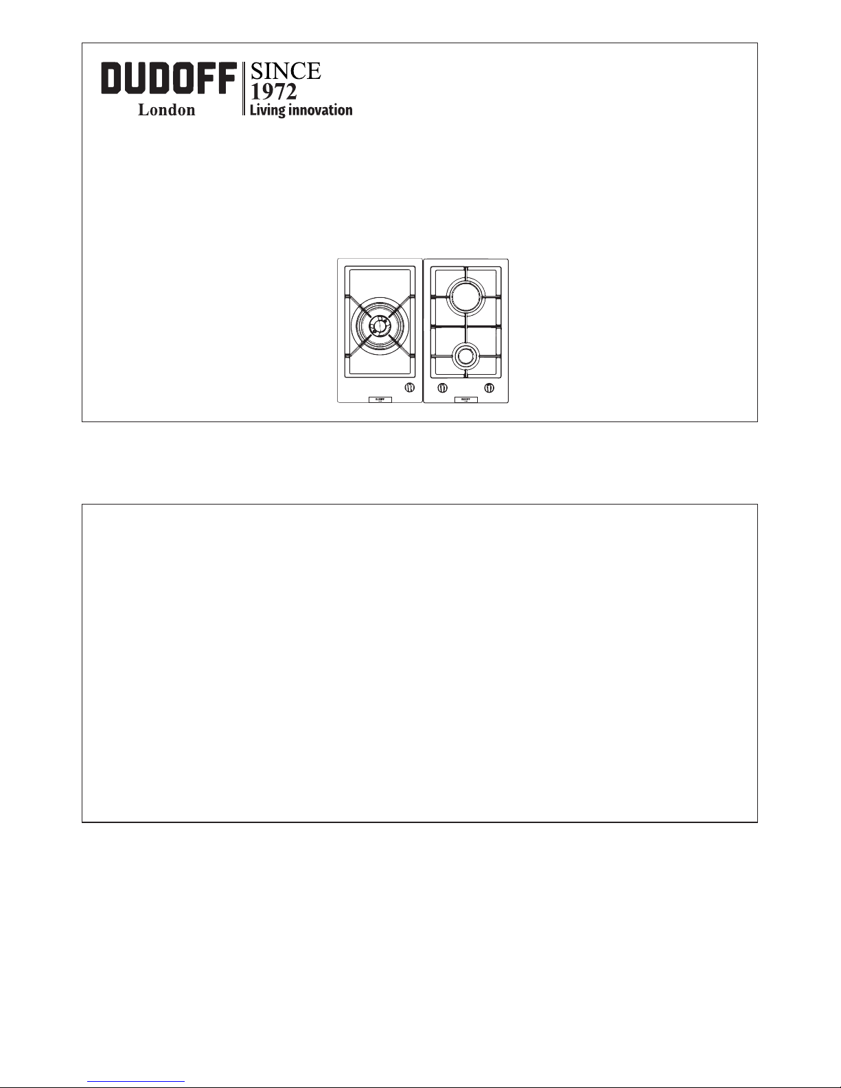
INSTALLATION AND USER INSTRUCTIONS
BUILT-IN GAS HOB DOMINO
GD-Z01 GD-Z02
Page 2
2
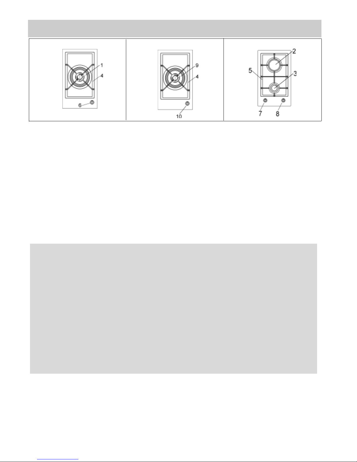
DESCRIPTION OF THE COOKTOP
1 Ultra rapid burner of 4000 W
2 Rapid gas burner of 2800 W
3 Auxiliary gas burner of 1000 W
4 Pan stand support 1F Wok
5 Pan stand support 2F
6 Burner n° 1 control knob
7 Burner n° 2 control knob
8 Burner n° 3 control knob
9 Dual complete of 4750 - 5000 W
10 Burner n° 9 control knob
Attention: this appliance has been manufactured for domestic use only and it employment by private
person.
WARNING:
Children less than 8 years of age shall be kept away unless
continuously supervised.
This appliance can be used by children aged from 8 years and
above and persons with reduced physical, sensory or mental
capabilities or lack of experience and knowledge if they have
been given supervision or instruction concerning use of the
appliance in a safe way and understand the hazards involved.
Children shall not play with the appliance.
Cleaning and user maintenance shall not be made by children
without supervision.
Page 3
3
USE
To use the WOK pan support on ultra rapid
gas burner only.
Put it on the ultra rapid pan support and
make sure of the stability (see fig. A).
Fig. A
1) TRADITIONAL BURNERS
On the surface of the hob, there is a serigraphic
figure above each knob, indicating the burner to
which the knob refers. After turning on the gas at
the main or opening the valve on the gas bottle,
light the burners as indicated below:
- automatic electric ignition
Press the knob corresponding to the burner to use
and turn it clockwise to the “Maximum” position
(big flame fig. 1) pressing the knob right down.
- Lighting burners fitted with a safety cut-off
device
For burners fitted with a safety cut-off device, turn
the knob corresponding to the burner to use anticlockwise to the “Maximum” position (big flame
fig. 1) until it stops and then press the knob.
Continue pressing the knob for about 10 seconds
after the burner has been lit.
Should the flames accidentally go out, turn the
burner control knob off and wait at least 1 min befor
attempting to light it again.
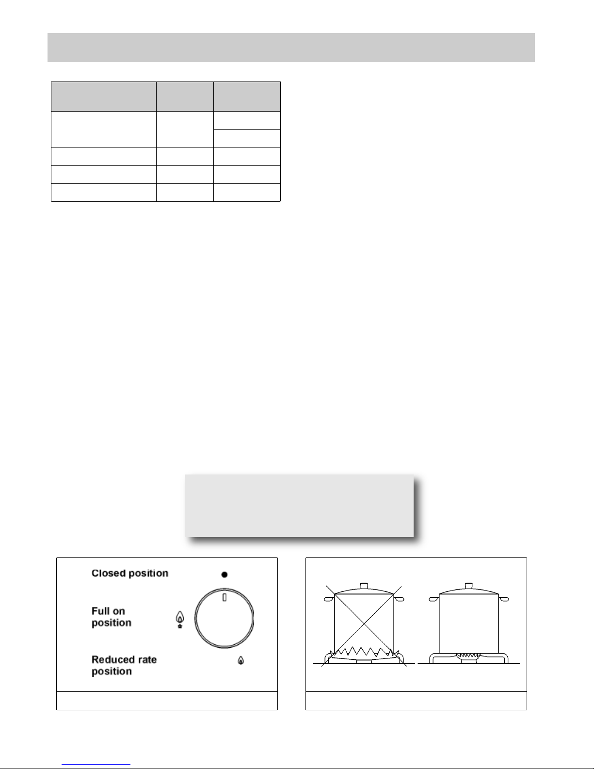
How to use the burners
To obtain maximum performance with minimum gas
consumption, remember the following:
- use suitable pans for each burner (see the table
below and fig. 2).
- When boiling point is reached, turn the knob to the
“Minimum” position (small flame fig. 1).
- Always use pans with lids.
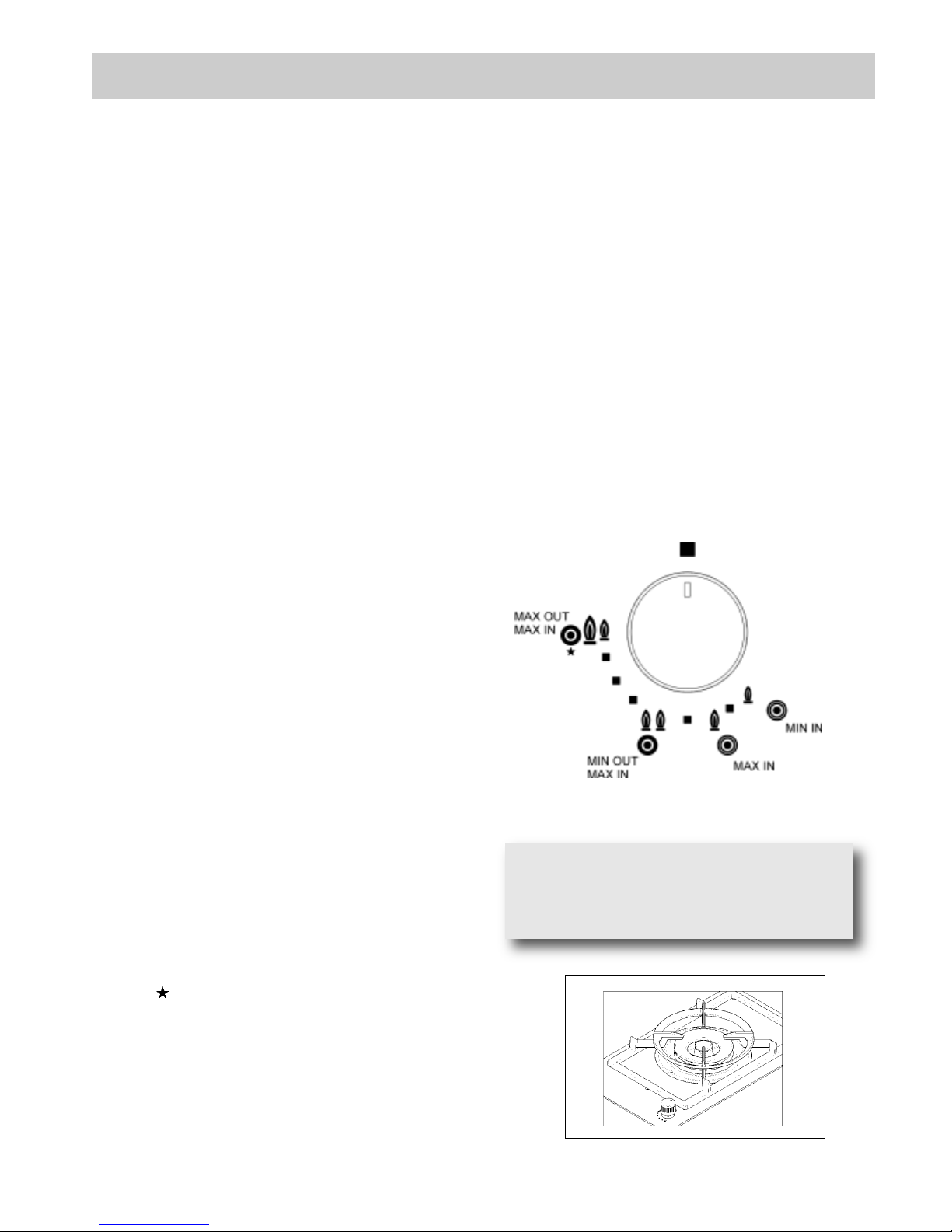
“DUAL” burner:
separate regulation of the inner and outer rings (in
practical terms, a dual burner controlled by a single
knob), offering very flexible use thanks to the
possibility to light either the inner flame only or the
whole burner (inner and outer flame at the same
time).
LIGHTING AND USING THE “DUAL” BURNER
Stand the pan on the burner before lighting.
Despite being controlled by a single knob, the
“DUAL” burner can be used in two different ways.
A) - Using the complete burner:
starting from the off position ● You must first press
the knob, simultaneously turning it anti-clockwise,
until the indicator points to the maximum delivery
position obtaining the maximum flow capacity of
both flames.
When the flames are lit, keep the knob pressed for
a few seconds, until the device automatically keeps
the burner lit.
It is now possible to regulate the intensity of the
flame by turning the knob anti-clockwise (from the
maximum flow capacity position of the inner and
outer flames to the maximum flow capacity of the
inner flame and the minimum of the outer flame.
To turn off the burner, turn the knob clockwise,
realigning the indicator with the ● off symbol.
B) - Using the inner flame only:
after lighting the burner and regulating the inner
flame to maximum flow capacity and the outer
flame to minimum flow capacity as described
above, turn the knob anti-clockwise until it clicks
once. The inner flame is now at maximum flow
capacity while the outer flame is turned off.
Continue turning anti-clockwise to regulate the inner
flame to the minimum flow capacity.
Turning off:
to turn off the burner, turn the knob clockwise,
realigning the indicator with the ● off symbol.
Once the “DUAL” burner is operating in either of the
two modes described, it is possible to swap from
one mode to the other by simply pressing and
turning the knob to the position required:
Page 4
USE
WARNIN G: d uring oper atio n the work
surfaces of the cooking area become very
hot: keep children away!
FIG. 1
4
WARNINGS:
- burners fitted with safety cut-off devices can
only be lit when the knob is in the “Maximum”
position (big flame fig. 1).
- In the absence of electricity, the burners can be
lit with matches.
- Never leave the appliance unattended while the
burners are in use and ensure that children are
kept at a safe distance. Make sure that pan
handles are correctly positioned and supervise
the cooking of foods in oil and fat, as these are
highly flammable.
- Do not use sprays near the appliance during
use.
- Do not drag pans across the glass hob as this
may scratch the surface.
- Do not use the hob as a work surface.
- Do not place pans with an unstable or deformed
bottom on the burner, as these may tip or spill
their contents, causing accidents.
- The pans must not extend beyond the edge of the
hob.
- Containers wider than the unit are not
recommended.
Burners
Power
(W)
Ø
Pan
(cm)
complete DUAL
central DUAL
4750-5000
900
22 ÷ 27
8 ÷ 16
Fast 2800 20 ÷ 22
Auxiliary 1000 10 ÷ 14
Ultra Rapid 4000 22 ÷ 26
FIG. 2
Page 5
5
USE
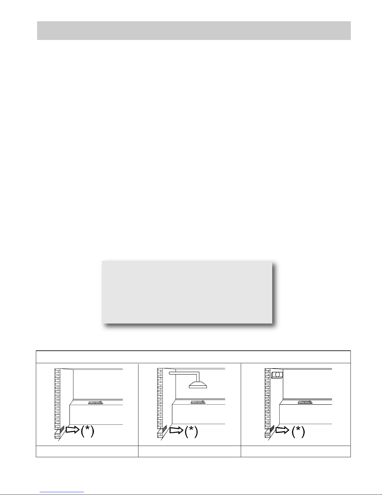
FIG. 3 FIG. 4 FIG. 5
(*) AIR INLET: SEE INSTALLATION CHAPTER (PARAGRAPHS 6 AND 7)
WARNINGS AND ADVICE FOR THE USER:
●Use of a gas cooking appliance produces heat and moisture in the room in which it is installed. The
room must therefore be well ventiladed by keeping the natural air vents clear (see fig. 3) and by
activating the mechanical aeration device (suction hood or electric fan fig. 4 and fig. 5).
●
Intensive and lengthy use of the appliance may require additional ventilation. This can be achieved by
opening a window or by increasing the power of the mechanical exhausting system if installed.
●Do not attempt to change the technical characteristics of the product because it can be dangerous.
●If you should not to use this appliance any more (or replace an old model), before disposing of it,
make it inoperative in conformity with current law on the protection of health and the prevention of
environmental pollution by making its dangerous parts harmless, especially for children who
might play on an abandoned appliance.
●Do not touch the appliance with wet or damp hands or feet.
●Do not use the appliance barefoot.
●The manufacturer will not be liable for any damage resulting from improper, incorrect or
unreasonable use.
●During, and immediately after operation, some parts of the cook top are very hot: avoid touching
them.
●After using the cook top, make sure that the knob is in the closed position and close the main tap
of the gas supply or gas cylinder.
●If the gas taps are not operating correctly, call the Customer Care Department.
CAUTION:
In case of hotplate glass breakage:
●shut immediately off all burners and any electrical
heating element and isolate the appliance from
the power supply;
●do not touch the appliance surface;
●do not use the appliance.
Page 6

6
CLEANING
Note: continuous use could cause
the burners to change colour due to
the high temperature.
IMPORTANT:
always disconnect the appliance from the gas
and electricity mains before carrying out any
cleaning operation
2) GAS HOB
Periodically wash the hot plate, the enamelled stell
pan support, the enamelled burner caps “A”, “B” and
“C” and the burner heads "T" (see fig. 6 and 7) with
lukewarm soapy water. They should also be cleaned
plugs "AC" and flame detection "TC" (see fig.6).
Clean them gently with a small nylon brush as shown
(see fig. 7/A) and allow to dry fully. Do not wash in
the dishwasher. It is very important to clean the
surface soon after every use, when the glass is still
tepid.
Do not allow vinegar, coffee, milk, salted water,
lemon or tomato juice from remaining in contact with
the enamelled surfaces for long periods of time.
Do not clean using abrasive metal scourers, powder
abrasives or corrosive sprays.
WARNINGS:
when reassembling the components, observe the
following recommendations:
- check that the holes in the burner heads “T”
(fig. 6) are not blocked by foreign bodies.
- Ensure that the enamelled covers “A”, “B” and
“C” (fig. 6 and 7) are correctly positioned on the
burner h ead . The covers a re cor rec tly
positioned on the head when they are perfectly
stable.
- If the opening and closing of any valve is
awkward, do not force it but request urgent
intervention by t he t ech nic al assi sta nce
service.
- The pa n suppo rt must be pla ced in the
appropriate cent eri ng p ins (Or on t he
aluminium profile if present). Verifying the
perfect stability.
- To prevent difficulties with lighting, regularly
clean the ignit ion elements (ceramic a nd
electrode) and safety cut-off devices (fig.7/A).
- Do not use jets of steam to clean the appliance.
IMPORTANT:
when removing the burners to clean them, ensure
that all parts are correctly positioned before relighting
them.
FIG. 6 FIG. 7/A
FIG. 7
Page 7

7
COMPLY WITH THE DIMENSIONS
(mm)
A B C D E F
1F-2F (30) 282 482 59 59 100 min 70 min.
TECHNICAL INF O R M ATIO N F O R
THE INSTALLER
Installation , adjust men ts of c ont rol s and
maintenance must only be carried out by a
qualified engineer.
The appliance must be correctly installed in
conformity with current law and the
manufacturer's instructions.
Incorrect installation may cause damage to
persons, animals or property for which the
Manufacturer shall not be considered
responsible.
During the life of the system, the automatic
safety or regulating devices on the appliance
may only be modified by the manufacturer or by
his duly authorized dealer.
3) INSTALLING THE COOKTOP
Check that the appliance is in a good condition after
having removed the outer packaging and internal
wrappings from around the various loose parts. In
case of doubt, do not use the appliance and contact
qualified personnel.
Never leave the packaging materials (cardboard,
bags, p oly sty ren e foam, n ail s, etc .) within
children’s reach since they cou ld become
potential sources of danger.
The measurements of the opening made in the top
of the modular cabinet and into which the cooktop
will be installed are indicated in either fig. 8. Always
comply with the measurements given for the hole
into which the appliance will be recessed (see fig. 8
and 9).
The prospective walls (left or right) that exceed the
working table in height m ust be at a minimum
distance from the cutting as mentionned both in the
columns “E” of the scheme.
The appliance belongs to class 3 and is therefore
subject to all the provisions established by the
provisions governing such appliances.
INSTALLATION
FIG. 9
FIG. 8
IMPORTANT!
A perfect ins tal lation, adjustment or
transformation of the cook top to use
oth er gase s requi res a QUA LIFIE D
INSTALLER: a failure to follow this rule
will void the warranty.
Page 8

8
INSTALLATION
4) FIXING THE COOKTOP
The cooktop has a special seal which prevents
liquid from getting into the cabinet. Strictly comply
with the following instructions in order to correctly
apply this seal:
- Take off all the movable parts of the hob.
- Cut the seal in 4 parts of the necessary lenght to
positionning it on the 4 edges of the glass.
- Overturn the cooktop and correctly position seal
“E” (fig. 10) under the edge of the cooktop itself,
so that the out er side o f t he sea l p erfe ctly
matches the outer edge of the cooktop. The ends
of the strips must fit together without overlapping.
- Evenly and securely fix the seal to the cooktop,
pressing into place with the fingers and remove
the strip of protective paper from the seal and set
the plate into the hole made in the cabinet.
- Position the hob in the hole in the unit and fasten it in
place using the appropriate screws “F” and the
fastening hooks “G” (fig. 11).
- When the appliance is installed so that the base
can be touched, we recommend fitting a protecting
shield. This sh ield mu st be at least
70 mm below the base of the bench top (fig. 8).
Timber or other suitable material may be used
provided it is capable of withstanding the appliance
temperatures. Ensure that the supply connection
point is accessible with the appliance installed. To
facilitate the shield may need to be removable.
NOTE: do not fix the cooktop into the bench with
sealant (ie silicon) as this may void the warranty.
Use only the seals provided.
FIG. 10 FIG. 11
FIG. 10/A
Caution: Do not allow the glass (A)
lay directly on the work top. it is the
bottomshelf (B) that has to be in
tou ch w ith the wor k t op (see
fig. 10/A).
Page 9

9
INSTALLATION
IMPORTANT INSTALLATION
SPECIFICATIONS
The installer should note that the appliance that
side walls should be no higher than the cooktop
itself. Furthermore, the rear wall, the surfaces
surrounding and adjacent to the appliance must
be able to withstand an temperature of 90 °C.
The adhesive used to stick the plastic laminate
to the cabinet must be able to withstand a
temperature of not less than 150 °C otherwise
the laminate could come unstuck.
The appliance must be installed in compliance
with the provisions in force.
This appliance is not connected to a device able
to dispose of the combustion fumes. It must
therefore be connected in compliance with the
abo ve m enti o ned inst allat ion stan dards .
Particular care should be paid to the following
provisions governing ventilation and aeration.
5) ROOM VENTILATION
It is essential to ensure that the room in which the
appliance is installed is permanently ventilated in
order to all ow the a ppl ian ce its elf t o ope rat e
corre ctly. the necess ary amo unt of ai r is that
required for regular gas combustion and ventilation
of the relative room, the volume of which must not
be less than 20 m3. Air must naturally flow through
permanent openings in the walls of the room in
question. These openings must vent the fumes
outdoors and their section must be at least 100 cm
2
(see fig. 3). Construction of the openings must
ensure that the openings themselves may never be
blocked. Indirect ventilation by air drawn from an
adjacent room is also permitted, in strict compliance
with the provisions in force.
CAUTION: if the burners of the cooking top are
without safety thermocouple, the ventilation
outlet must have a minimum 200 cm² section.
6) LOCATION AND AERATION
Gas cooking appliances must always dispose of
their combustion fumes through hoods. These must
be connected to flues, chimneys or straight outside.
If it is not possible to install a hood, an electric fan
can be installed on a window or on a wall facing
outside (see fig. 4). This must be activated at the
same time as the appliance (see fig. 5), so long as
the specifications in the provisions in force are
strictly complied with.
7) GAS CONNECTION
Before connecting the appliance, check that the
values on the data label affixed to the underside
of the cooktop correspond to those of the gas
and electricity mains in the home.
A label on the appliance indicates the regulating
conditions: type of gas and working pressure.
Gas connection must comply with the pertinent
standards and provisions in force.
Whe n gas is s uppli ed thr ough du cts,t he
appliance must be connected to the gas supply
system:
●with a rigid steel pipe. The joints of this pipe must
consist of threaded fittings conforming to the
standards.
●With copper pipe. The joints of this pipe must
consist of unions with mechanical seals.
●With seamless flexible stainless steel pipe. The
length of this pipe must be 2 meters at most and
the seals must comply with the standards.
Whe n t he gas is supp lied by a bott l e, the
appliance must be fuelled by a pressure governor
conforming to the provisions in force and must be
connected:
●with a copper pipe. The joints of this pipe must
consist of unions with mechanical seals.
●With seamless flexible stainless steel pipe. The
length of this pipe must be 2 meters at most and
the seals must comply with the standards. It is
advisable to apply the special adapter to the
flexible pipe. This is easily available from the
shops and facilitates connection with the hose
nipple of the pressure governor on the bottle.
●Wit h ru bber hos e pipe in comp lianc e with
standards. The diameter of this hose pipe must be
8 mm and its length must be no less than 400 mm
and no more than 1500 mm. It must be firmly fixed
to the hose nipple by means of the safety clamp
specified by standards.
At the connection end, verify the gasproof using a
soap solution, never a flame.
WARNINGS:
- remember that the ga s inlet union on the
appliance is a 1/2" gas conic male type in
compliance with EN 10226 standards.
- The appliance complies with the provisions of
the following EEC Directives:
CEE2009/142 regarding gas safety.
Page 10

10
INSTALLATION
8) ELECTRICAL CONNECTION
The electrical connections of the appliance must
be carried out in compliance with the provisions
and standards in force.
Before connecting the appliance, check that:
- The voltage matches the value shown on the
specification plate and the section of the wires of
the electrical system can support the load, which is
also indicated on the specification plate.
- The electrical capacity of the mains supply and
current sockets suit the maximum power rating of
the appliance (consult the data label applied to the
underside of the cooktop).
- The socke t or system has an efficient earth
connection in compliance with the provisions and
standards in force. The manufacturer declines all
responsibility for failing to comply with these
provisions.
When the ap pliance i s conn ect ed to the
electricity main by a socket:
- Fit a standard plug suited to the load indicated on
the data label to the cable.
- Fit the wires following figure 12, taking care of
respecting the following correspondences:
letter L (live) = brown wire;
letter N (neutral) = blue wire;
earth symbol = green - yellow wire.
- The power supply cable must be positioned so that
no part o f it is abl e to reach an temperature
of 90 °C.
- Never use reductions, adapters of shunts for
connection since these could create false contacts
and lead to dangerous overheating.
When the appliance is connected straight to the
electricity main:
- Install an omnipolar circuit-breaker between the
appliance and the electricity main. This circuitbreaker should be sized according to the load rating
of the appliance and possess a minimum 3 mm gap
between its contacts.
- Rememb er that the earth wire must not be
interrupted by the circuit-breaker.
- The electrical connection may also be protected by
a high sensitivity differential circuit- breaker.
You are strongly advised to fix the relative yellowgreen earth wire to an efficient earthing system.
Before performing any service on the electrical
part of the appliance, it must absolutely be
disconnected from the electrical network.
WARNINGS:
all our products are conform with the European
Norms and relative amendments. The product is
therefore conform with the requirements of the
European Directives
in force relating to:
- compatibility electromagnetic (EMC);
- electrical security (LVD);
- re str iction o f use of ce rta in ha zar dou s
substances (RoHS);
- EcoDesign (ERP).
IMPORTANT!
The appliance must be installed following
the manufacturer's instr uctions. The
manufacturer will not be liable for injury
to per sons or an imals o r p rope r ty
dam age cause d by an inc orrec t
installation.
If the installation requires modifications to
the h ome' s electrical syst em or if the
socket is incompatible with the appliance's
plu g , hav e chan ges or repl a ceme nts
per formed by pro fess iona lly-qua lifi ed
person. In particular, this person must also
make sure that the section of the wires of
the s ocke t is su itabl e for t he po wer
absorbed by the appliance.
FIG. 12
Page 11

11
INSTALLATION
8/A) INSTALLING THE HOT PLATE
WITH THE BATTERY
Check that the appliance is in a good condition after
having removed the outer packaging and internal
wrappings from around the various loose parts. In
case of doubt, do not use the appliance and contact
qualified personnel.
Never leave the packaging materials (cardboard,
bags, p oly sty ren e foam, n ail s, etc .) within
children’s reach since they cou ld become
potential sources of danger.
The measurements of the opening made in the top
of the modular cabinet and into which the hot plate
will be installed are indicated in either fig. 8. Always
comply with the measurements given for the hole
into which the appliance will be recessed (see fig. 8
and 9).
The appliance belongs to class 3 and is therefore
subject to all the provisions established by the
provisions governing such appliances.
8/B) FIXING THE HOT PLATE
The hot plate has a special seal which prevents liquid
from infiltrating into the cabinet. Strictly comply with
the following instructions in order to correctly apply
this seal:
- take off all the movable parts of the hob.
- Detach the seals from their backing, checking that
the transparent protection still adheres to the seal
itself.
- Overturn the hot plate and correctly position seal
“E” (fig. 10) under the edge of the hot plate itself, so
that the outer side of the seal perfectly matches the
outer perimetral edge of the hot plate. The ends of
the strips must fit together without overlapping.
Evenly and securely fix the seal to the cooktop,
pressing into place with the fingers and remove
the strip of protective paper from the seal and set
the plate into the hole made in the cabinet.
- Unscrew the ignition cap “T” (see fig. B) and fit a
1.5 V battery (not included in the appliance) with
the positive “+” polarity turn inside.
Rescrew the cap.
- Position the hob in the hole in the unit and fasten it in
place using the appropriate screws “F” and the
fastening hooks “G” (fig. 11).
- I n order to avoid acci dental touch with the
overheating bottom of the hob, during the working,
is necessary to put a wooden insert, fixed by
screws, at a minimum distance of 70 mm from the
top (see fig. 8).Remark: below is the suggested
clearances. Actual installation will be veried subject
to different kitchen situations.
REPLACING THE BATTERY
To change the battery (see fig. B) comply with
following instructions:
- unscrew cap “T” and remove exausty battery.
- Insert a 1.5 V new battery. The positive polarity “+”
is turn over inside.
- Rescrew the cap “T”.
- Re-assembly all the movable parts.
WARNING:
the batteries contain a dangerous material for our
ambient. Always put them in a separate and safe
container.
If you eliminate your appliance, remember to take off
the battery.
FIG. B
IMPORTANT: T he b att ery c an be
rechargeable or not rechargeable.
The rechargeable battery shall be removed
from appliance before being recharged.
Do not att emp t t o recharge the not
rechargeable batteries.
The power supply poles shall not be short
circuited.
Page 12

12
Always disconnect the appliance from the
electricity main before making any adjustments.
All seals must be replaced by the technician at
the end of any adjustments or regulations.
Our burn ers do not require primar y air
adjustment.
9) TAPS
“Reduced rate” adjustment
Switch on the burner and turn the relative knob to
the “Reduced rate” position (small flame fig. 1).
- Remove knob “M” (fig. 13 and 13/A) of the tap,
which is simply pressed on to its rod. The by-pass
for minimal rate regulation can be: beside the tap
(fig. 13) or inside the shaft. In any case, to access
to regulation, it can be done trought the insertion of
a small screwdriver ‘’D’’ beside the tap (fig. 13) or in
the hol e ‘’ C’’ in sid e the sha ft o f th e ta p
(fig 13/A). Turn the throttle screw to the right or left
until the burner flame has b een a dequatel y
regulated to the “Reduced rate” position.
The flame should not be too low: the lowest small
flame should be continuous and steady. Re-assemble
the several components.
It is understood that only burners operating with
Natural should be subj ect ed to t he above
mentioned adjustments. The screw must be fully
locked when the burners operate with Liquid
Petroleum (LPG) gas.
ADJUSTMENTS
WARNING:
To adjust the minimum “DUAL” burner first
remove the bushing “E” (fig. 13).
In t he case of a “DUAL” bur ner, th e
regulation screw situated inside the post of
the valve regulates the central flame, while
the screw next to the valve regulates the
outer flame.
FIG. 13/AFIG. 13
TAPS LUBRIFICATION
Should a tap being blocked, do not
force and ask for Technical
Assistance.
Page 13

13
10) REPLACING THE INJECTORS
The burners can be adapted to different types of gas by
mounting injectors suited to the type of gas in question.
To do this, first remove the burner tops using a wrench
“B”. Now unscrew injector “A” (see fig. 14) and fit a
injector corresponding to the utilized type of gas in its
place.
It is advisable to strongly tighten the injector in place.
After the injectors have been replaced, the burners
must be regulated as explained in paragraphs 9.
Th e technician must reset any seals on the
regulating or pre-regulating devices.
The envelope with the injectors and the labels can
be included in the kit, or at disposal to the
authorized Customer Care Department.
For the sake of convenience, the nominal rate table
also lists the heat inputs of the burners, the diameter
of the injectors and the working pressures of the
various types of gas.
CONVERSIONS
BURNER ARRANGEMENT ON THE COOKTOP
FIG. 14
BURNERS
GAS
NORMAL
PRESSURE
mbar
NORMAL
RATE
INJECTOR DIAMETER
1/100 mm
NOMINAL HEAT
INPUT (W)
N°
DESCRIPTION
gr/h l/h Min. Max.
1
ULTRA RAPID
Version 4kW
G30 - BUTANE
G31 - PROPANE
G20 - NATURAL
30
30
20
244
239
319
100 B
100 B
145 A
1800
1800
1800
4000
4000
4000
2
RAPID
G30 - BUTANE
G31 - PROPANE
G20 - NATURAL
30
30
20
204
200
267
83
83
117 Y
800
800
800
2800
2800
2800
3
AUXILIARIY
G30 - BUTANE
G31 - PROPANE
G20 - NATURAL
30
30
20
73
71
95
51
51
75 x
450
450
450
1000
1000
1000
9
ULTRA RAPID**
DUAL 5 kW
G30 - BUTANE
G31 - PROPANE
G20 - NATURAL
30
30
20
345
357
476
2 x 72B + 4 6B
2 x 72B + 4 6B
2 x 115 A + 71A
2700
2700
2700
4750
5000
5000
DUAL CENTRAL
G30 - BUTANE
G31 - PROPANE
G20 - NATURAL
30
30
20
65
64
86
46 B
46 B
71 A
300
300
300
900
900
900
FIG. 14/A
** Mount with bushing (B) if present (see Fig. 14/A).
Page 14

14
SERVICING
Always disconnect the a ppl ian ce fro m the
electricity and gas mains before proceeding with
any servicing operation.
11) REPLACING COOKTOP PARTS
Replacement of the components housed inside the
appliance: remove the trivets, knobs and flanges
unscrewing the screws “V” (fig.16) and remove the
glass (see fig. 15).
After having carried out the above listed operations,
the burners, taps (fig. 17) and electrical components
can all be replaced (fig. 18).
It is advisable to change seal "D" (fig.17) whenever
a tap is replaced to ensure a perfect tightness.
Greasing the taps (see fig. 19)
If a tap bec omes sti ff to o per ate , it must be
immediately greased in compliance with the following
instructions:
- remove the tap.
- Clean the cone and its housing using a cloth
soaked in diluent.
- Lightly spread the cone with the relative grease.
- Fit the cone back in place, operate it several times
and then remove it again. Eliminate any excess
grease and check that the gas ducts have not
become clogged.
- Fit all parts back in place, complying with the
demounting order in reverse.
- Check the tightness by using soapy water. The use
of the flame is prohibited.
To facilitate the servicing technician’s task, here is a
chart with the types and sections of the powering
cables and the ratings of the electrical components.
WARNING: MAINTENANCE MUST ONLY BE
PERFORMED BY AUTHORISED PERSONS.
FIG. 18 FIG. 19
FIG. 15 FIG. 16 FIG. 17
Page 15

15
SERVICING
Gas cooktop H05 RR - F Section 3 X 0.75 mm
2
TYPE OF TYPE OF SINGLE - PHASE
COOKTOP CABLE POWER SUPPLY
CABLE TYPES AND SECTIONS
ATTENTION!!!
If the power supply cable is replaced, the installe should leave the ground wire longer than the phase (B)
conductors (fig. 20) and comply with the recommendations given in paragraph 8.
FIG. 20
In case of failure or cut in the cable, please move away from the cable and
do not touch it. Moreover the device must be unplugged and not switched
on. Call the nearest authorized service center to fix the problem.
TECHNICAL DATA FOR THE
APPLIANCE GAS REGULATION
Page 16

16
TECHNICAL ASSISTANCE AND SPARE PARTS
Before leaving the factory, this appliance will have been tested and regulated by expert and specialized
personnel in order to guarantee the best performances.
Any repairs or adjustments which may be subsequently required may only be carried out by qualified
personnel with the utmost care and attention.
For this reason, always contact your Dealer or our nearest After Sales Service Center whenever repairs or
adjustments are required, specifying the type of fault and the model of the appliance in your possession.
Please also note that genuine spare parts are only available from our After Sales Service Centers and
authorized retail outlets.
The above data are printed on the data label put on the inferior part of the appliance and on the packing label.
The above informations give to the technical assistant the possibility to get fit spare parts and a heaven-sent
intervention. We suggest to fill the table below.
MARK: .............................................................................
MODEL: ...........................................................................
SERIES: ...........................................................................
This appliance is marked according to the European directive 2002/96/EC on Waste
Electrical and Electronic Equipment (WEEE).
This guideline is the frame of a European-wide validity of return and recycling on
Waste Electrical and Electronic Equipment.
TECHNICAL DATA ON THE DATA LABEL
GAS MODELS
1 BURNERS
UR 4 kW
Category = III
G 30 - Butane = 30 mbar
G 31 - Propane = 30 mbar
G 20 - Natural = 20 mbar
Σ Qn Gas Natural = 4.0 kW
Σ Qn Butane = 291 gr/h (G30)
Voltage = 220-240 V ~
Frequency = 50 Hz
If with battery:
Voltage = 1.5 V
2 BURNERS
Category =III
G 30 - Butane = 30 mbar
G 31 - Propane = 30 mbar
G 20 - Natural = 20 mbar
Σ Qn Gas Natural = 3.8 kW
Σ Qn Butane = 276 gr/h (G30)
Voltage = 220-240 V ~
Frequency = 50 Hz
If with battery:
Voltage = 1.5 V
1 BURNERS
5 kW DUAL
Category = III
G 30 - Butane = 30 mbar
G 31 - Propane = 30 mbar
G 20 - Natural = 20 mbar
Σ Qn Gas Natural = 5.0 kW
Σ Qn Gas Butane = 4.75 kW
Σ Qn Butane = 345 gr/h (G30)
Voltage = 220-240 V ~
Frequency = 50 Hz
If with battery:
Voltage = 1.5 V
 Loading...