

Page 1
INSTALLATION AND USER INSTRUCTIONS
BUILT-IN GAS HOB (TOUCH CONTROL)
Page 2
2
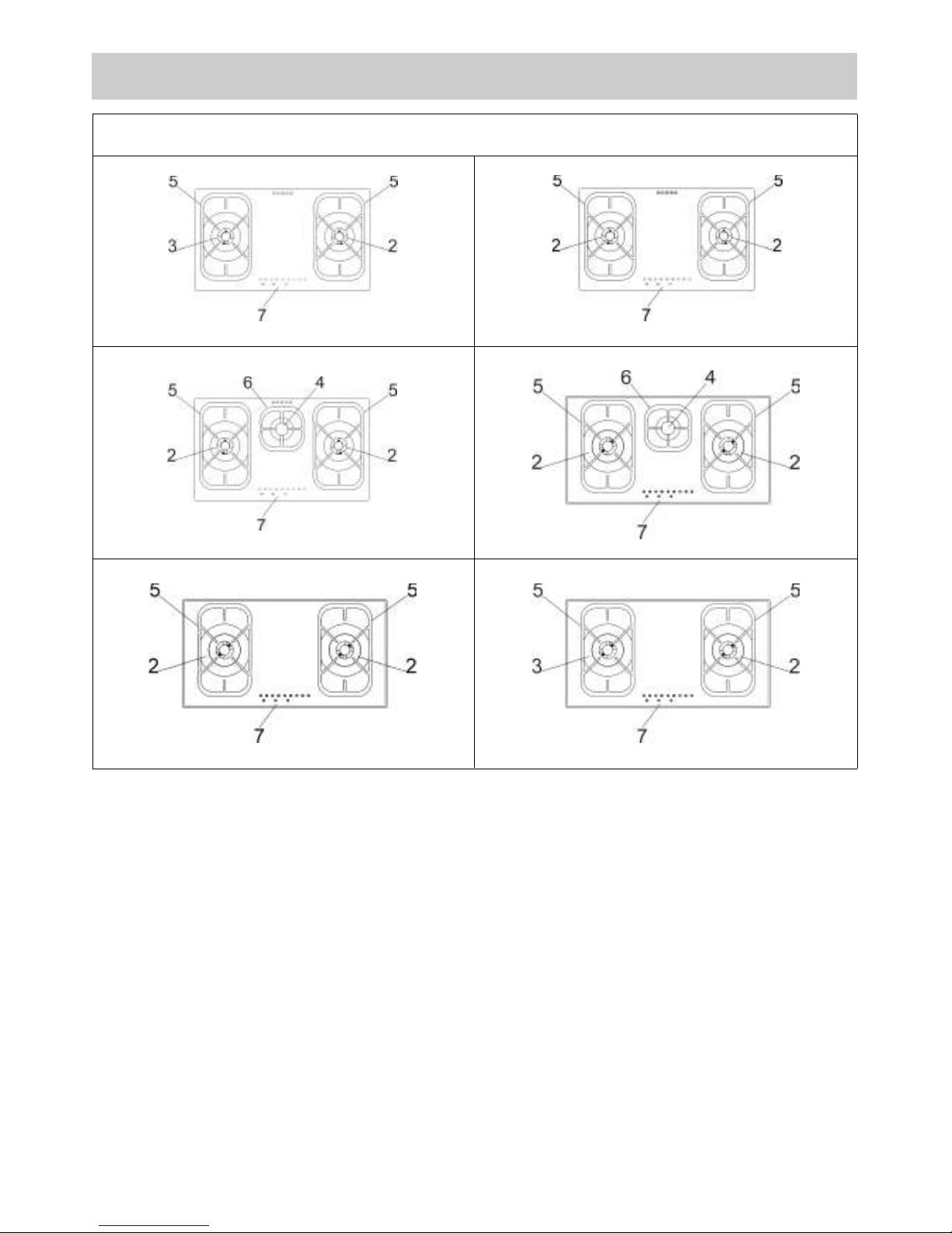
DESCRIPTION OF HOBS
2 Triple Ring 3750 - 3800 W
3 DUAL burner 4200 W
4 Auxiliary burner 1000 W
5 Grid lateral
6 Grid central
7 Touch control
Hob equipped with electronic burner management system, with touch panel burner control.
Caution: this appliance has been designed for domestic use in domestic environments by members
of the general public. It must be used by fully aware adults. Children should not be allowed to
approach or play with the appliance. The easy-to-reach front areas of the appliance may become
extremely hot during use.
Supervise children and incapacitated people during use, making sure that they do not touch hot
surfaces and stay away from the appliance during operation.
TYPE: MCGOG
78 cm.
78 cm.
78 cm.
86 cm.
86 cm.
86 cm.
Page 3
3
USE
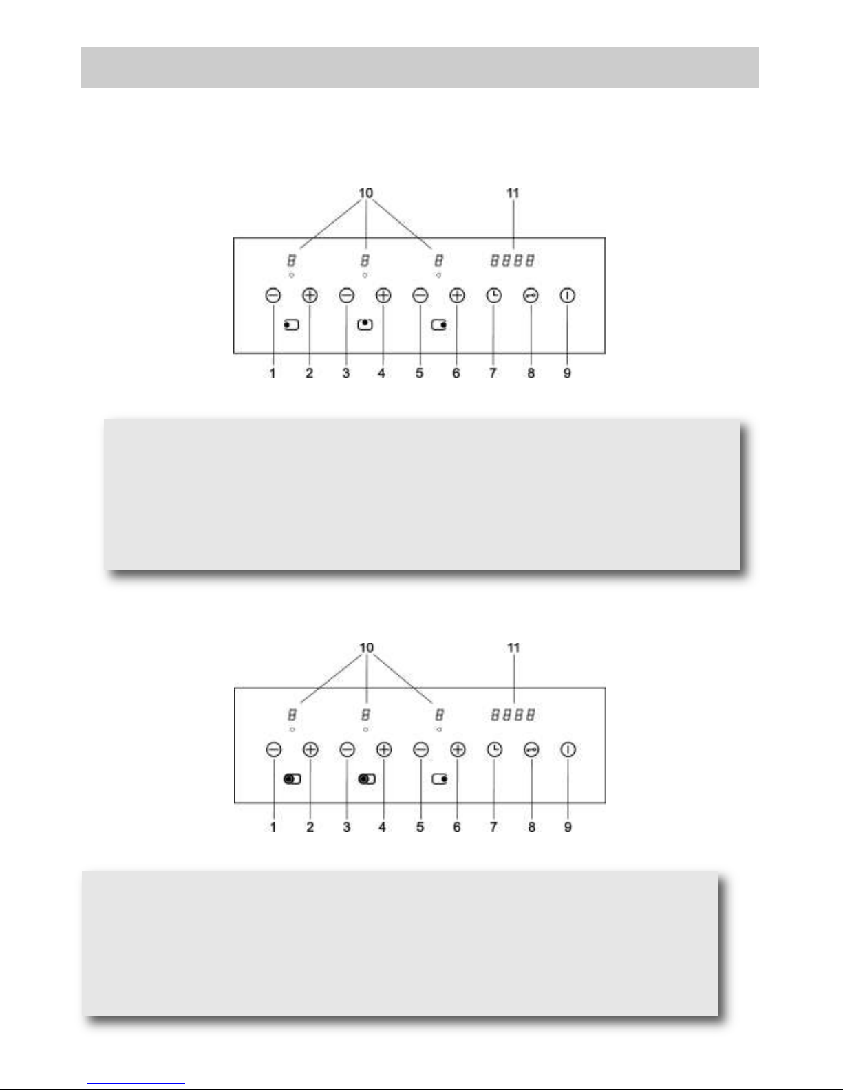
1 - Burner 2 – button (left)
2 - Burner 2 + button (left)
3 - Burner 4 – button
4 - Burner 4 + button
5 - Burner 2 – button (right)
6 - Burner 2 + button (right)
7 - Clock button
8 - Safety lock button
9 - ON/OFF button
10 - Capacity levels display (0 - 9)
11 - Display clock
DESCRIPTION OF THE FRONT PANEL CONTROLS
3F of 78/86 cm.
2F of 78/86 cm. (DUAL)
1 - Burner 3 – button (crown internal and external)
2 - Burner 3 + button (crown internal and external)
3 - Burner 3 – button (crown internal)
4 - Burner 3 + button (crown internal)
5 - Burner 2 – button
6 - Burner 2 + button
7 - Clock button
8 - Safety lock button
9 - ON/OFF button
10 - Capacity levels display (0 - 7)
11 - Display clock
Page 4
4
FUNCTIONS available to the user/fitter:
the main functions of the device are:
● standby mode (burners off, control panel active).
● Control panel lock to protect against accidental lighting/programming.
● Regulation of the capacity of every burner at 9 levels (7 levels for the hobs with DUAL burner).
● Safety lock with manual reset via release procedure carried out from the control panel.
● Procedure to regulate the capacity to the minimum level for every burner (for fitter only).
● Programming the type of fuel used: methane/lpg (for fitter only).
● Programming of the switch off time for every burner.
● Maximum duration time for each burner pre-programmed into the FLASH memory equates to 4
hours.
● Temperature measured on the electronic card.
● Management of anomalies/faults via code indicated on display.
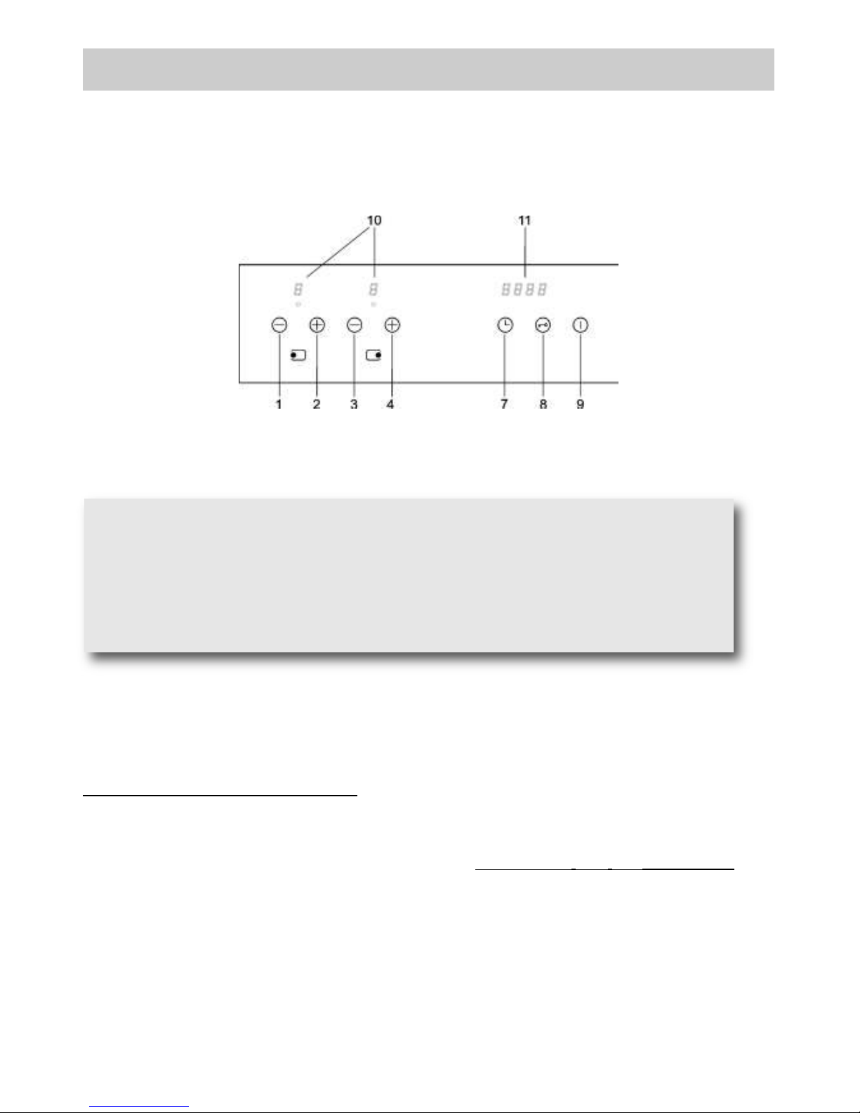
2F DA 78/86 cm.
USE
1 - Burner 2 – button (left)
2 - Burner 2 + button (left)
3 - Burner 2 – button (right)
4 - Burner 2 + button (right)
7 - Clock button
8 - Safety lock button
9 - ON/OFF button
10 - Capacity levels display (0 - 9)
11 - Display clock
Page 5
1) BURNERS
On the surface of the hob, there is a serigraphic figure above each knob, indicating the burner to which
the knob refers. After turning on the gas at the main or opening the valve on the gas bottle, light the
burners as indicated below.
Switching on the Hob
To switch on the hob, press the ON/OFF button constantly for at least 2 seconds. The hob will come on
and the displays related to the burners will show level zero, corresponding to the status of burners off.
Lighting a burner
To light the burner 2 (or the burner 4), press and release the + button of the burner you wish to light. You
have 3 seconds to press the + button again to light the burner at level 9, otherwise, if you press the –
button, it will be lit at level 5. The control system will now make a maximum of 3 attempts at intervals of 10
seconds.
Should the burner fail to light after the third attempt, it locks and the corresponding Led displays the letter
“b”. To release the burner, see the relative procedure further ahead.
Every burner for which the relative timer has not been programmed will switch off automatically after 4
hours of constant operation.
The ignition of the burner is also indicated by the relative indicator, which remains active the whole time
the burner is lit.
Regulating the burner flame level
With the burner lit, to increase the capacity level you must press the + button, while it is necessary to
press the - button to reduce the capacity level. To obtain a continuous variation in the capacity level, it is
sufficient to keep the + or - button pressed and release it at the level required. The capacity level varies
from 1 to 9.
5
USE
The Dual burner, instead, can be lit partially (internal ring) or completely (internal and external ring)
depending on which buttons are pressed to light the burner. In particular, to light the internal ring only,
press button 4, and then you will have 3 seconds time to press button 4 again and light the burner at
level 7.
To light the internal and the external ring simultaneously, press button 2, and then you will have 3
seconds time to press button 2 again and light both burner rings at level 7.
If you wish to light the external burner ring when the internal ring is already lit, this will anyway involve
switching off the internal ring and then lighting it again.
The Dual burner, instead, can be adjusted in two ways depending on whether it is lit partially (internal
ring) or completely (internal and external ring). When the internal ring only is lit, press button 4 to
increase the capacity level, or press button 3 to decrease it. To obtain a continuous variation in the
capacity level, you just need to keep button 4 or 3 pressed and then release it at the required level.
The capacity level can vary from 1 to 7.
When the internal ring is lit together with the external one, to increase the capacity level you can press
button 2 or 4 indifferently, as the level variation will occur on both rings simultaneously, while to
decrease the capacity level press button 1 or 3 (to obtain a continuous variation in the capacity level,
you just need to keep the button pressed and then release it at the required level). Also in this case the
capacity level can vary from 1 to 7.
Page 6
Switching off a burner
To switch off a burner it is necessary to press the + and - button simultaneously for a moment.
The corresponding Led will display the letter “H” (hot) for a few minutes to indicate that the burner is hot.
Switching off all the burners
To switch off all the burners at the same time, simply press the ON/OFF button. This will place the hob in
OFF status.
Programming the burner switch-off time
It is possible to independently programme each burner to switch off automatically after a specific length of
time.
To programme the timer of a burner, press the Clock button (7). On time display the writing TIME will
appear. Now pressing - or + button of the burner to be timed, the writing TIME disappears and the writing
0:00 will appear. The burner selected is identified by the relative flashing indicator (flashing fast). The
timer display will indicate 0.00, meaning that the timer related to the burner selected is not active. To
programme the switch-off time of the burner selected, press the Clock button (7) again; the timer display
will indicate 0.00. The flashing digit to the left of the dot indicates the hours, while those to the right
indicate the minutes. By pressing buttons - and + of the burner selected it is possible to increase or
decrease the operating hours from 0 to 9. Keeping buttons + or - pressed (of the burner selected) the
change in the number of hours will take place continuously.
To specify the number of minutes, press the Clock button (7) again. The digits to the right of the dot will
start flashing. Set the minutes in the same way as indicated for the hours.
When programming the time it is possible to zero the current setting at any time by pressing buttons - and
+ (of the burner selected) together. A time equal to zero deactivates the burner timer. To confirm the time
shown on the display, press the Clock button (7). At this point, only the indicators of the burners with the
timer active continue to flash.
Press the Clock button (7) to return to timer programming mode and see the time remaining until switchoff or to change the current settings. If no button is pressed for more than 10 seconds during
programming, the programming procedure is interrupted automatically and the main display returns. Any
settings being changed on the burner selected will not be lost and the relative time is active.
The timer can be programmed both with the burner switched off or lit, and the counter will start
immediately after the time programmed has been confirmed. When the time is up, the timed burner will be
switched off and a sequence of acoustic signals lasting 30 seconds will be emitted (this acoustic signal
can be stopped by pressing the Clock button (7).
If the user switches off a burner, the relative timer is deactivated.
6
USE
The Dual burner, instead, can be switched off in two ways depending on whether it is lit partially
(internal ring) or completely (internal and external ring). Both when the internal ring only is lit and when
the internal ring is lit together with the external one, press button 4 and 3 simultaneously for a short
time to switch off the burner completely. In case the internal ring is lit together with the external one,
and you wish to switch off the external burner ring only, press button 2 and 1 simultaneously for a short
time.
It is possible to programme the timer of a lit burner only, and in the case of a Dual burner, this
possibility is limited to the internal ring.
The timer programme of a Dual burner will always be effective after switching off the burner
completely, both in case the internal ring only was lit and in case both burner rings were lit.
Page 7
7
USE
Regulating the clock
Following interruptions to the power supply, it is necessary to set the time displayed by the clock inside
the hob.
To regulate the clock, press the buttons 7 and 8 together for at least 3 seconds.
The flashing digit to the left of the dot indicates the hours, while those to the right indicate the minutes. It
is possible to increase or decrease the hours using buttons 2 or 1 and by keeping buttons 2 or 1 pressed
the change in the number of hours takes place continuously.
To regulate the minutes, press the Clock button (7) again. The digits to the right of the dot will start
flashing. Now change the minutes in the same way as indicated for the hours.
Press the Clock button (7) to memorise the time programmed.
Releasing the burner
When a burner is locked the relative display shows the letter “b”. The burner is released by pressing
buttons 1 and 8 together constantly for at least 2 seconds. When released, the burners are reset to level
0, ready to be lit again.
N.B: if the release procedure is repeated 5 times in a row during a 15 minute time span, the device will
indicate FLT06 and will accept no further request for release for another 15 minutes.
Locking the control panel
This is activated by pressing button 8 only for at least 2 seconds. All burner levels will remain stable. The
control panel locked status occurs when the decimal points on the display of the capacity level related to
each burner light up. While the control panel is locked it is no longer possible to change the levels of the
burners or change the timer settings, but it is possible to switch off the hob by pressing the ON/OFF
button (safe switch-off).
It is not possible to release a locked burner when the control panel lock is active. It will be therefore
necessary to release the control panel before activating the burner release procedure.
Releasing the control panel
The control panel is released by pressing button 8 and button 2 for at least 2 seconds. The control panel
is released when the flame level points on the display go out.
Child lock function (for the hobs with DUAL burner).
It is activated only with hob off by pressing the button 8 for at least 3 seconds. The activation of the
Child Lock function is visible through the switching on of the decimal points on the flow rate level
displays of each burner and entails the complete lock of the keyboard.
The function is deactivated by pressing again the button 8 for at least 3 seconds (the unlock of the
keyboard is visible through the switching off of the decimal points on the flow rate level displays).
It is not possible to release a locked burner when the control panel lock is active. It will be therefore
necessary to release the control panel before activating the burner release procedure.
Page 8

8
USE
WARNINGS:
- never leave the appliance unattended while the
burners are in use and ensure that children
are kept at a safe distance. Make sure that pan
handles are correctly positioned and
supervise the cooking of foods in oil and fat,
as these are highly flammable.
- Do not use sprays near the appliance
during use.
- Do not drag pans across the glass hob as this
may scratch the surface.
- Should a crack appear on the surface of the
glass, disconnect the appliance from the
electricity supply immediately.
- Do not use the hob as a work surface.
- Do not place pans with an unstable or deformed
bottom on the burner, as these may tip or spill
their contents, causing accidents.
- The pans must not extend beyond the edge of
the hob.
- The machine must not be used by people
(including children) with impaired mental or
physical capacities, or without experience of
using electrical devices, unless supervised or
instructed by an expert adult responsible for
their care and safety. Children should not be
allowed to play with the equipment.
- Containers wider than the unit are not
recommended.
Warning:
during operation the work surfaces of the
cooking area become very hot: keep children
away!
Burners Power W Ø pan cm
DUAL total
4200 22 ÷ 27
DUAL central
900 8 ÷ 16
Auxiliary 1000 16 ÷ 18
Triple Ring
3800-3750 24 ÷ 26
WARNING:
Children less than 8 years of age shall be kept away unless
continuously supervised.
This appliance can be used by children aged from 8 years and
above and persons with reduced physical, sensory or mental
capabilities or lack of experience and knowledge if they have
been given supervision or instruction concerning use of the
appliance in a safe way and understand the hazards involved.
Children shall not play with the appliance.
Cleaning and user maintenance shall not be made by children
without supervision.
Page 9

9
FIG. 1 FIG. 2 FIG. 3
(*) AIR INLET: SEE INSTALLATION CHAPTER (PARAGRAPHS 5 AND 6)
USE
WARNINGS AND ADVICE FOR THE USER:
- use of a gas cooking appliance produces heat and moisture in the room in which it is installed. The
room must therefore be well ventilated by keeping the natural air vents clear (fig. 3) and by
activating the mechanical aeration device (suction hood or electric fan fig. 4 and fig. 5).
- Intensive and lengthy use of the appliance may require additional ventilation. This can be achieved
by opening a window or by increasing the power of the mechanical exhausting system if installed.
- Do not attempt to change the technical characteristics of the product because it can be dangerous.
- If you should not to use this appliance any more (or replace an old model), before disposing of it,
make it inoperative in conformity with current law on the protection of health and the prevention of
environmental pollution by making its dangerous parts harmless, especially for children who
might play on an abandoned appliance.
- Do not touch the appliance with wet or damp hands or feet.
- Do not use the appliance barefoot.
- The manufacturer will not be liable for any damage resulting from improper, incorrect or
unreasonable use.
- During, and immediately after operation, some parts of the cook top are very hot: avoid touching
them.
- After using the cook top, make sure that the knob is in the closed position and close the main tap
of the gas supply or gas cylinder.
- If the gas taps are not operating correctly, call the Customer Care Department.
CAUTION:
In case of hotplate glass breakage:
●shut immediately off all burners and any electrical
heating element and isolate the appliance from
the power supply;
●do not touch the appliance surface;
●do not use the appliance.
Page 10

10
CLEANING
CAUTION:
before cleaning the appliance, disconnect it
from the gas and electricity supplies.
2) WORKTOP
It is very important to clean the hob every time you
use it, while the glass is still warm.
Do not clean using abrasive metal scourers, powder
abrasives or corrosive sprays.
Depending on the degree of dirt, we recommend:
- for light stains, a damp sponge is sufficient.
Be aware that the razor can cause wounds.
- Traces of liquid spilled from pans can be
eliminated with vinegar or lemon juice.
- Never allow sugar or sugary foods to fall on the
hob while cooking. Should this occur, switch off
the hob and clean it immediately with hot water.
- As time goes by metallic reflections, colouring or
scratches may appear due to poor cleaning and
the incorrect movement of pans. Scratches are
hard to eliminate but do not affect the correct
operation of your hob.
Periodically wash the hot plate, the enamelled stell
pan support, the enamelled burner caps “A”, “B”
and “C” and the burner heads "T" (see fig. 4 and
5) with lukewarm soapy water. They should also
be cleaned plugs "AC" and flame detection "TC"
(see fig. 4). Clean them gently with a small nylon
brush as shown (see fig. 6) and allow to dry fully.
Do not wash in the dishwasher. It is very important
to clean the surface soon after every use, when
the glass is still tepid.
Do not allow vinegar, coffee, milk, salted water,
lemon or tomato juice from remaining in contact
with the enamelled surfaces for long periods of
time.
WARNINGS:
comply with the following instructions, before
remounting the parts:
●check that burner head slots “T” (fig. 4) have
not become clogged by foreign bodies.
●Check that enamelled burner cap “A-B-C”
(fig. 4-5) have correctly positioned on the
burner head. It must be steady.
●Burned food on an electric plate must be
removed dry.
●After use, pour a little lukewarm oil on the
plate and wipe it with a cloth.
●The pan support must be placed in the
appropriate centering pins verifying the
perfect stability.
●
Correctly preserve the plate after use by
treating it with special products, easily
available at the supermarket. This will keep
the surface of the plate clean and bright. This
operation will also prevent the formation of
rust.
●Don’t use steam jets for the equipment
cleaning.
Note:
continuous use could cause the burners to
change colour due to the high temperature.
FIG. 6
FIG. 5
FIG. 4
Page 11

11
INSTALLATION
FIG. 7 FIG. 8
MEASUREMENTS TO OBSERVE (in mm)
TECHNICAL INFORMATION
FOR FITTERS
Installation and all the regulation,
transformation and maintenance operations
listed in this section must be carried out
exclusively by qualified personnel.
The appliance must be correctly installed in
conformity with current law and the
manufacturer's instructions.
Incorrect installation may cause injury to people
or animals, or damage to items, for which the
manufacturer cannot be held responsible.
Throughout the life of the system, the devices
for the safety and automatic regulation of the
appliances must only be modified by the
manufacturer or the duly authorised supplier.
INDICATIONS FOR INSTALLATION
●The device is designed to remain operational for
less than 24 h (non-permanent operating system).
When this limit is reached, a regulation stoppage
occurs so the device can check its efficiency.
●This automatic device is a safety device and must
not be altered. Interference with this device will
eliminate any responsibility by the manufacturer
and invalidate the warranty.
●Observe the national and European standards
applicable (e.g., EN 60335-1/EN 50165) in
relation to electrical safety.
●Before entry into operation, check the wiring
carefully: incorrect wiring may damage the device
and jeopardise the safety of the system.
●Connect and disconnect the hob only after cutting
off the electricity supply.
●Avoid exposing the device to drops of water.
●Avoid laying the valve wires along with the high
voltage wires of the ignition transformer.
●Ensure that there is nothing on the hob,
particularly on the area of the control panel, before
switching on.
●After switching on the hob, wait a few seconds to
complete the automatic calibration procedure of
the control panel.
●In the event of a “partial” short circuit or insufficient
insulation between the line and earth, the voltage
on the sensor electrode may be reduced so much
that it causes the device to lock, due to the
impossibility to sense the flame signal.
●The extra low voltage (ELV) circuit is not safe to
touch (only main insulation in compliance with
EN 60730-1), so the installation must guarantee
the level of protection against electric shock
equivalent to double insulation for the user
interface.
A B C D E
2F - 3F (78)
705 405 95 95 97.5 min.
2F - 3F (86)
705 405 95 95 97.5 min.
Page 12

12
INSTALLATION
3) INSERTING THE HOB
After removing the outer and inner packing of the
various mobile parts, ensure that the hob is
undamaged. If you are in any doubt, do not use
the appliance and contact qualified personnel.
The packing elements (cardboard, bags,
polystyrene, nails must not be left within the
reach of children as they are potential sources
of danger.
Make a hole in the worktop to accommodate the
hob, using the measurements indicated in fig. 7,
ensuring that the critical dimensions of the space
in which the appliance must be installed are
observed (see fig. 8).
The appliance must belong to class 3 and is
therefore subject to all the indications of the
standards for such appliances.
The appliance can be installed with just one lateral
wall (to the right or left of the hob), higher than the
hob and positioned at a minimum distance as
described in the table below.
3A) CYLINDER HOLDER COMPARTMENT
The dimensions of the cylinder compartment have to
permit the easy loading and unloading of the cylinder.
For an efficient aeration is necessary to make some
small openings in the furniture, as per fig. 9/A
and 9/B.
The cylinder holder compartment must have the
following characteristics:
- resistance to a load.
- No fitment of the cylinder directly on the floor are
allowed.
- The cylinder equipped with governor must be set or
take off from the compartment in a easy way.
- The cylinder cock must be easily accessible.
- The flexible tube musn't be in contact with sharp
edges.
- The cylinder holder compartment and the different
parts of the unit, where the burners are fit, musn't be
in touch inside.
- The aeration openings musn't be occluded when the
unit is installed.
The appliance belongs to class 3 and is therefore
subject to all the provisions established by the
provisions governing such appliances.
IMPORTANT:
a perfect installation, adjustment or
transformation of the cook top to use other
gases requires a QUALIFIED INSTALLER: a
failure to follow this rule will void the
warranty.
FIG. 9/A FIG. 9/B
CAUTION: do not place the glass directly
on the unit. The bottom of the hob must
rest on the unit.
Page 13

13
INSTALLATION
4) FITTING THE HOB
The hob is equipped with a special seal to avoid
any infiltration of liquid into the unit. To apply this
seal correctly, please follow the instructions given
below carefully:
- remove all the mobile parts of the hob.
- Cut the seal into 4 strips of the lengths suitable to
fit it along the 4 sides of the glass.
- Turn the hob upside down and place the adhesive
side of the seal “E” (fig. 10/A) correctly under the
edge of the hob so that the outer edge of the seal
perfectly matches the outer perimeter edge of the
glass. The ends of the strips must match without
overlapping.
- Stick the seal to the glass evenly and securely,
using your fingers to press it into place.
- Position the hob in the hole in the unit and fasten it in
place using the appropriate screws “F” of the
fastening hooks “G” (see fig. 10/B).
- In order to avoid accidental contact with the
surface of the box of the overheated hob during
use, it is necessary to install a wooden divider at a
minimum distance of 70 mm from the top,
fastening it in place with screws (fig. 7).
- To fasten this product to the supporting structure,
we advise you not to use mechanical or electrical
screwdrivers and to exercise moderate pressure
by hand on the fastening hooks.
IMPORTANT INSTALLATION
INSTRUCTIONS
The appliance can be installed with just one
lateral wall (to the right or left of the hob),
higher than the hob and positioned at a
minimum distance as indicated in figure 7.
Moreover, the rear wall and the surfaces
adjacent to and surrounding the hob must
resist an temperature of 90 °C.
The glue which joins the plastic laminate to the
unit must be able to resist temperatures of at
least 150 °C to prevent the coating from
becoming unstuck.
The appliance must be installed in compliance
with the indications of the standards in force.
This appliance is not connected to a device for
the evacuation of the combust products.
Consequently it must be connected in
compliance with the installation instructions
mentioned earlier. Particular attention must be
paid to the information on ventilation and
aeration provided below.
5) VENTILATION
The room where the appliance is installed must be
permanently ventilated to guarantee its correct
operation. The amount of air necessary is that
required for the correct combustion of gas and the
ventilation of the room, which must measure at
least 20 m3. The natural airflow must take place
directly through permanent openings made in the
walls of the room to be ventilated, which lead
outside and have a minimum section of 100 cm
2
(see fig. 3). These openings must be made so that
they cannot be blocked.
Indirect ventilation is also allowed by drawing in air
from rooms next to that to be ventilated, absolutely
observing the indications of the standards in force.
6) POSITIONING AND AERATION
Gas hobs must always eliminate the products of
combustion through hoods connected t o
chimneys, flues or directly outside (see fig. 2). If it
is not possible to fit a hood, a fan installed in a
window or an outside wall can be used
simultaneously with the appliance (see fig. 3), as
long as the provisions concerning ventilation listed
in the standards in force are strictly observed.
FIG. 10/A FIG. 10/B
Page 14

14
INSTALLATION
7) GAS CONNECTION
Before connecting the appliance, ensure that
the data on the label applied to the lower part
is compatible with that of the gas distribution
network.
A printed label of this booklet and one applied
to the underside of the hob indicate the
instructions for regulating the appliance: type
of gas and working pressure.
When the gas is distributed through channels,
the appliance must be connected to the gas
delivery system:
●with hard steel piping compliant with the
standards in force, the joints of which must be
made using threaded fittings compliant
with EN 10226.
●with copper piping compliant with the standards
in force, the joints of which must be made using
mechanical seal fittings compliant with the
standards in force.
●with continuous wall stainless steel flexipipe,
compliant with the standards in force, with a
maximum extension of 2 metres and seals
compliant with the standards in force. This pipe
must be installed so that it cannot come into
contact with the moving parts of the module it is
built into (drawers for instance) and must not
cross compartments that can be filled.
When the gas is delivered directly from a
bottle, the appliance, fed with a pressure regulator
compliant with the standards in force must be
connected:
●with copper piping compliant with the standards
in force, the joints of which must be made using
mechanical seal fittings compliant with the
standards in force.
●With continuous wall stainless steel flexipipes,
compliant with the standards in force, with a
maximum extension of 2 metres and seals
compliant with the standards in force. This pipe
must be installed so that it cannot come into
contact with the moving parts of the module it is
built into (drawers for instance) and must not
cross compartments that can be filled. We advise
the application of a special adapter (easily
available on the market) to the flexipipe, to
facilitate the connection with the hose support of
the pressure regulator mounted on the bottle.
When the connection is complete, check that it is
perfectly sealed, using a soapy solution and never
a flame.
WARNINGS:
- remember that the gas entry fitting of the
appliance is a 1/2” threaded conic gas male
fitting compliant with EN 10226.
- The appliance is compliant with the
indications of the following European
Directives:
CEE 2009/142 in relation to gas safety.
Moreover, the walls and the surfaces adjacent to
and surrounding the hob must resist an
temperature of 90 ° C.
FIG. 10/C
Caution: Do not allow the glass (A)
lay directly on the work top. it is the
bottomshelf (B) that has to be in
touch with the work top (see
fig. 10/C).
Page 15

15
INSTALLATION
8) ELECTRICAL CONNECTION
The electrical connection must be made in
compliance with the standards and legal
provisions in force.
Before making the connection, ensure that:
- the voltage matches the value shown on the
specification plate and the section of the wires of
the electrical system can support the load, which
is also indicated on the specification plate.
- The socket or system has an effective earth
connection in compliance with the standards and
legal provisions currently in force. We cannot
accept any responsibility for failure to observe
these provisions.
When the appliance is connected to the power
supply via socket:
- fit a standard plug suited to the load indicated on
the label to the power cable “C” if necessary.
- Connect the wires in compliance with the diagram
in fig. 11, ensuring that the following are observed:
letter L (phase) = brown wire;
letter N (neutral) = blue wire;
earth symbol = green-yellow wire.
- The power cable must be positioned so that it
does not reach an temperature of 90 °C in any
point.
- Do not use reductions, adapters or shunts for the
connection, as they could make false contacts
causing hazards due to overheating.
- The socket must be accessible after fitting.
When the connection is made directly to the
electricity main:
- insert an omnipolar switch between the appliance
and the power network, in a size suited to the load
of the appliance, with a minimum aperture
between contacts of 3 mm.
- Remember that the earth cable must not be
interrupted by the switch.
- The electrical connection may also be protected
with a highly sensitive differential switch.
We strongly recommend that you connect the
appropriate green-yellow earth wire to an efficient
earth system.
Before performing any service on the electrical
part of the appliance, it must absolutely be
disconnected from the electrical network.
The manufacturer declines all responsibility for
damages suffered by people and items due to
failure to observe the aforementioned indications,
or deriving from interference with a single part of
the appliance.
WARNINGS:
all our products are conform with the
European Norms and relative amendments.
The product is therefore conform with the
requirements of the European Directivesin
force relating to:
- compatibility electromagnetic (EMC);
- electrical security (LVD);
- restriction of use of certain hazardous
substances (RoHS);
- EcoDesign (ERP).
IMPORTANT!
The appliance must be installed following
the manufacturer's instructions. The
manufacturer will not be liable for injury
to persons or animals or property
damage caused by an incorrect
installation. If the installation requires modifications
to the home's electrical system or if the
socket is incompatible with the
appliance's plug, have changes or
replacements performed by
professionally-qualified person. In
particular, this person must also make
sure that the section of the wires of the
socket is suitable for the power absorbed
by the appliance.
FIG. 11
Page 16

16
The regulation operations listed below are reserved to qualified fitters only. After carrying out any
regulation or pre-regulation operations, any seals must be replaced by the technician. The
regulation of primary air to our burners is not necessary.
9) PROCEDURE FOR REGULATING THE MINIMUM CAPACITY OF THE
BURNERS
The procedure for acquiring the minimum capacities allows the modification of the minimum capacity
programmed, adapting every burner to the characteristics of the gas distribution network to which the hob
is connected.
The procedure is activated by pressing the 2, 1 and 4 buttons continuously for 3 seconds, with all the
burners switched off (standby).
The activation of the regulation procedure is indicated on the display with the word “MIN”. At this point it is
possible to select the burner to be regulated using buttons + and -. After confirmation the burner selected
ignites at the minimum and the capacity can be increased or decreased to the minimum level using the +
and - buttons of the burner. During the display regulation procedure, the flame display levels will show the
indication - if the minimum level programmed corresponds with the factory setting, and the indication will
change ⊓or ⊔in flashing mode, indicating a higher or lower capacity than that programmed.
To confirm the minimum capacity required, it is necessary to press the Clock button (7). The word “MIN”
will continue to be present and none of the leds will flash. At this point it is possible to press the Clock
button (7) to exit the procedure, or press buttons + and - to select another burner and programme its
minimum capacity. The minimum capacity levels will then be acquired and memorised by the device, and
will be used in the normal use of the hob (see fig. 12).
Selecting the type of gas
It is possible to configure the hob to work with methane gas of lpg. To activate the gas selection
procedure, the hob must be working and all the burners must be switched off. Simply press the 2, 1 and 3
buttons for at least 3 seconds. The start of the gas selection procedure is indicated by the switch-off of
the burner level displays and the appearance of “Met” or “Lpg” on the timer display, depending on the
current configuration. It is possible to select the setting required, using buttons 2 and 1. To complete the
procedure the operator must press the Clock button (7).
The activation of this function implicates the cancellation of any switch-off times programmed for the
burners (see fig. 12).
THE BURNERS DO NOT REQUIRE ANY REGULATION OF THE PRIMARY AIR.
FIG. 12
REGULATION AND TRANSFORMATION OPERATIONS
Adjusting the minimum capacity of the external ring of the Dual burner will anyway involve lighting the
internal burner ring at its minimum level.
Page 17

17
REGULATION AND TRANSFORMATION OPERATIONS
10) REPLACING NOZZLES
The burners can be adapted to suited different
types of gas by fitting the nozzles that correspond
to the gas used. To do this, it is necessary to
remove the burner heads and use a straight key
“B”, to unscrew the nozzle “A” (see fig. 13) and
replace it with a nozzle corresponding to the gas
used.
We advise you to block the nozzle tightly.
After making these replacements, the
technician must regulate the burners as
described in paragraph 9, seal any regulation
or pre-regulation organs and apply the label
corresponding to the new gas regulation
carried out on the appliance in place of that
previously applied. This label is contained in
the spare nozzle bag.
For the ease of the fitter, we have prepared a table
indicating the flow capacities, the heat capacities
of the burners, the diameter of the nozzles and the
working pressure for the various types of gas.
ARRANGEMENT OF THE BURNERS
TABLE
78 cm.
86 cm.
FIG. 13
BURNERS
GAS
WORKING
PRESSURE
mbar
HEAT
CAPACITY
NOZZLE
DIAMETER
1/100 mm
HEAT
CAPACITY (W)
No.
DESCRIPTION
g/h l/h Min. Max.
2
TIPLE RING
G30 - BUTANE
G31 - PROPANE
G20 - NATURAL
28 - 30
37
20
276
271
357
100 B
100 B
145 A
1800
1800
1800
3800
3800
3750
3
DUAL
total
G30 - BUTANE
G31 - PROPANE
G20 - NATURAL
28 - 30
37
20
345
339
476
2 x 69A + 46 B
2 x 69A + 46 B
2 x 110 A + 71 A
1800
1800
1800
4200
4200
4200
DUAL
central
G30 - BUTANE
G31 - PROPANE
G20 - NATURAL
28 - 30
37
20
65
64
86
46 B
46 B
71 A
450
450
450
900
900
900
4
AUXILIARY
G30 - BUTANE
G31 - PROPANE
G20 - NATURAL
28 - 30
37
20
73
71
95
50
50
72 X
450
450
450
1000
1000
1000
Page 18

18
REGULATION AND TRANSFORMATION OPERATIONS
Display of the temperature inside the hob
There is a temperature sensor inside the electronic card with which it is possible to show the temperature
inside the hob directly on the timer display. The display is activated by pressing the 2 and 1 buttons with
buttons 7 and 8 continuously for at least 3 seconds. In this condition it is no longer possible to use button
7 for settings related to the programming of the burner switch-off time. The same sequence of buttons
used to activate the inner display of the temperature must be used to deactivate it.
Electronic self-diagnosis
The electronic cards constantly control their own status. Should hardware problems or faults inside the
card occur, such as to jeopardise the safety of the end user, the device enters a “safe” status in which the
solenoids are switched off and a code relating to the type of fault appears on the display.
One burner in lockout status
No gas supply
Restore the gas supply and then reset
the burners from lockout
The ionization electrode needs to be
cleaned or is not in contact with the
flame
Clean the electrode or adjust its position
and then reset the burners from lockout
Device not connected to earth
Check the wiring and then reset the
burners from lockout
Extraneous light / flame detection circuit
anomaly on a single burner
Ionization electrode incorrect wiring Check the wiring
Circuit failure Replace the device
Main valve control circuit anomaly Circuit failure Replace the device
Reference voltage circuit anomaly Circuit failure Replace the device
Watchdog circuit anomaly Circuit failure Replace the device
Microcontroller port anomaly Circuit failure Replace the device
EEPROM anomaly Circuit failure Replace the device
Valve driving circuit anomaly Circuit failure Replace the device
Driving anomaly on valve A Valve A incorrect wiring
Cut off the power supply, check valve A
wiring and then restore the power
supply
Driving anomaly on valve B Valve B incorrect wiring
Cut off the power supply, check valve B
wiring and then restore the power
supply
Driving anomaly on valve C Valve C incorrect wiring
Cut off the power supply, check valve C
wiring and then restore the power
supply
Driving anomaly on valve F Valve F incorrect wiring
Cut off the power supply, check valve F
wiring and then restore the power
supply
Max. limit of 5 resets in 15 minutes
exceeded
The burner reset procedure has been
carried out more than 5 times in 15
minutes
Wait 15 minutes and then reset the
burners from lockout
Power supply circuit anomaly Circuit failure Replace the device
Generic anomaly
The power supply to the device has
been cut off further to another type of
failure previously occurred
Reset the burners from lockout
Resonator anomaly Circuit failure Replace the device
All burners in lockout status
No gas supply
Restore the gas supply and then reset
the burners from lockout
The ionization electrodes need to be
cleaned or are not in contact with the
flame
Clean the electrodes or adjust their
position and then reset the burners from
lockout
Device not connected to earth
Check the wiring and then reset the
burners from lockout
Gas leakage from a valve causing the
unwanted ignition of a second burner
during the ignition of the first one.
The flame on in the second burner for
more than 10 seconds causes this type
of anomaly.
Replace the faulty valve
Control logic communication errors Circuit failure Replace the device
Keyboard control error
A mechanical deformation may have
jeopardized the keyboard good
positioning on the glass surface
Wait a few seconds for the keyboard
recalibration; if the error persists, cut off
and then restore the power supply; if the
error still persists, replace the device
Keyboard hardware error Circuit failure
Make sure that the keyboard card is
correctly inserted into the connector.
If yes, replace the device
Keyboard hardware error Circuit failure
Make sure that the keyboard card is
correctly inserted into the connector.
If yes, replace the device
Page 19

19
REGULATION AND TRANSFORMATION OPERATIONS
MEASUREMENTS
(electronic card)
Page 20

20
FIG. 17 FIG. 18
FIG. 14 FIG. 15 FIG. 16
MAINTENANCE
Before carrying out any maintenance,
disconnect the appliance from the gas and
electricity supplies.
INDICATIONS FOR INSTALLATION
• The device is designed to remain operational for
less than 24 h (non-permanent operating system).
When this limit is reached, a regulation stoppage
occurs so the device can check its efficiency.
• This automatic device is a safety device and must
not be altered. Interference with this device will
eliminate any responsibility by the manufacturer
and invalidate the warranty.
• Observe the national and European standards
applicable (e.g., EN 60335-1/EN 50165) in
relation to electrical safety.
• Before entry into operation, check the wiring
carefully: incorrect wiring may damage the device
and jeopardise the safety of the system.
• Connect and disconnect the hob only after cutting
off the electricity supply.
• Avoid exposing the device to drops of water.
• Avoid laying the valve wires along with the high
voltage wires of the ignition transformer.
• Ensure that there is nothing on the hob,
particularly on the area of the control panel, before
switching on.
• After switching on the hob, wait a few seconds to
complete the automatic calibration procedure of
the control panel.
• In the event of a “partial” short circuit or insufficient
insulation between the line and earth, the voltage
on the sensor electrode may be reduced so much
that it causes the device to lock, due to the
impossibility to sense the flame signal.
• The extra low voltage (ELV) circuit is not safe to
touch (only main insulation in compliance with
EN 60730-1), so the installation must guarantee
the level of protection against electric shock
equivalent to double insulation for the user
interface.
11) REPLACING COMPONENTS
To replace the components housed inside the hob
it is necessary to remove the flanges by loosening
the screws (fig. 14), removing the ceramic glass
surface.
After carrying out the operations listed above, it is
possible to replace the solenoids (fig. 15 - 16), the
electrical components and the electronic card
(fig. 17 - 18).
We advise you to change the seal “D” (fig. 16) every
time you replace a solenoid, in order to guarantee a
perfect seal between the body and the ramp.
To facilitate the work of the maintenance operator,
we have prepared a table, printed on the next page,
indicating the power cable types and sections.
Page 21

21
FIG. 19
MAINTENANCE
POWER CABLE TYPES AND SECTIONS
TYPE OF HOB TYPE OF POWER
CABLE
MONOPHASE
CAUTION!!!
When replacing the power cable, the fitter must keep the earth conductor “B” longer than the phase
conductor (fig. 19) and must also observe the warnings indicated in paragraph 8.
Gas hob H05 RR-F Section 3 x 0.75 mm
2
WARNING: MAINTENANCE MUST ONLY BE
PERFORMED BY AUTHORISED PERSONS.
In case of failure or cut in the cable, please move
away from the cable and do not touch it. Moreover
the device must be unplugged and not switched on.
Call the nearest authorized service center to fix the
problem.
Page 22

22
TECHNICAL DATA
DESCRIPTION
The electronic card enables the management of a gas hob with 2/3 burners.
This device works in conjunction with the Brahma VPC01 valves, which allow the regulation of the capacity
of each individual burner powered by methane gas or lpg.
The device is also made up of a user interface with display in seven segments and a touch panel.
MAIN FEATURES
The basic features are listed below:
• display in 7 red segments and leds for indication of the capacity level of each individual burner, for
indicating the time and settings.
• A touch panel with 9 touch-sensitive areas to select the level of each individual burner, settings, control
panel lock and light-up/ switch-off.
• Three 24Vdc outputs for Brahma VPC01 modulating valves.
• 24Vdc output for Brahma VPC01 main valve after the gas manifold.
• RS232 interface for the device diagnostics.
• Three faston inputs for the flame sensor electrodes of the five burners.
• Output for piloting a 220-240 Vac igniter.
• Management of modulation levels pre-programmed into the FLASH memory.
• Possibility for the management of two modulation tables (G20 and G30).
• Procedure incorporated into the device for regulating the minimum level for each burner.
• Power supply card created using switching technology.
• Daily clock in 24h format.
TECHNICAL DATA
Power supply:
100 - 240V a.c. ±10%
Frequency:
50 - 60Hz
Absorption:
30VA
Ignition transf. output contacts:
220 - 240V a.c. ±10% – 250mA – cosφ = 0,4
Sensor electrodes connection:
2.8 x 0.8 mm faston
Working temperature:
-10 °C ÷ +85 °C
Degree of protection:
IP 00
Classification code EN298:
Specific Character Code
1° Atmospheric A
2° Direct ignition of the main burner M
3°
Repetition of cycle C
4°
Non-volatile lock L
5°
Set times X
6°
Non-permanent operation N
Maximum length of the wires of external components:
≤1m
Flame control
The flame sensor device using straightening property of the flame.
Minimum ionisation current: 0.2µA
DC
Maximum ionisation current: (power supply voltage 264V
RMS
) 4.5µA
DC
Recommended ionisation current: 3 ÷ 5 times the minimum
Maximum length of cable: 1 m
Minimum insulation resistance of the electrode and the measuring cable towards earth: ≥ 50M
Ω
Max. electrode parasite capacity: ≤1nF
Max. short-circuit current: ≤ 200µA
AC
TIMES
- waiting time (TW):
1s
- safety time (TS):
4s
- intervention time in the event of switch-off: 3s (compliant with EN 30-1-4)
- inter-waiting or inter-ventilation time: 10s
- waiting time for lock caused by parasite flame: 10s
- pre-ignition time: 0s
- number of ignition attempts: 3
Page 23

23
TECHNICAL DATA PRINTED ON THE LABEL
2 BURNERS (86)
( 1 DUAL + 1 Triple Ring )
G30 - BUTANE = 28 - 30 mbar
G31 - PROPANE = 37 mbar
G20 - NATURAL = 20 mbar
Σ
Qn
Natural Gas
G20 = 7.95 kW
Σ
Qn
BUTANE Gas G30 =
8.0 kW
Σ
Qn
BUTANE Gas =
582 g/h (G30)
571 g/h (G31)
Voltage = 220-240 V ~
Frequency = 50/60 Hz
3 BURNERS (86)
( 2 Triple Ring + 1 AUXILIARY )
G30 - BUTANE = 28 - 30 mbar
G31 - PROPANE = 37 mbar
G20 - NATURAL = 20 mbar
Σ
Qn
Natural Gas
G20 = 8.5 kW
Σ
Qn
BUTANE Gas G30 =
8.6 kW
Σ
Qn
BUTANE Gas G30
= 625 g/h (G30)
614 g/h (G31)
Voltage = 220-240 V ~
Frequency = 50/60 Hz
TECHNICAL DATA OF THE APPLIANCE GAS REGULATION
Page 24

24
TECHNICAL ASSISTANCE AND SPARES
Before leaving the factory, this appliance was tested and regulated by specially qualified experts in order to
guarantee the best operating results.
The original spare parts can be found only in our Technical Assistance Centres and authorised shops.
Every repair or regulation operation which should become subsequently necessary must be carried out with
the utmost care and attention by qualified personnel.
This is why we recommend that you always contact the Dealer who sold the appliance or our nearest
Assistance Centre, specifying the brand, the model, the serial number and the type of problem affecting your
appliance. The pertinent data is stamped on the label applied to the underside of the appliance and on the
label applied to the packing box.
This information enables the technical assistance department to acquire the appropriate spare parts and
consequently guarantee prompt and targeted intervention. We recommend that you write this data in the
spaces below and keep it to hand at all times:
BRAND: .......................................................
MODEL: .......................................................
SERIES: .......................................................
This appliance is marked according to the European directive 2002/96/EC on
Waste Electrical and Electronic Equipment (WEEE).
This guideline is the frame of a European-wide validity of return and recycling on
Waste Electrical and Electronic Equipment.
 Loading...