

DUDOFF G02-Z1, G02-Z2, G03-Z2, G03-Z1, G02-Z3 Installation And User Instructions Manual
...Page 1
The Manufacturer shall not be held responsible for any inaccuracies in this handbook due to printing or
transcription errors; the designs in the figures are purely indicative. The Manufacturer also reserves the right
to make any modifications to the products as may be considered necessary or useful, also in the interests of
the user, without jeopardizing the main functional and safety features of the products themselves. This cook
top was designed to be used exclusively as a cooking appliance: any other use (such as heating
rooms) is to be considered improper and dangerous.
COD. 04067MU - 20.09.2016
Dear Customer,
thank you for having purchased one of our products.
We are certain that this new, modern, functional and practical appliance, built with the very highest
quality materials, will meet your requirements in the best possible way. This appliance is easy to
use. It is, however, important to thoroughly read the instructions in this handbook in order to obtain
the best results.
These instructions are only valid for the countries of destination, the identification symbols
of which are indicated on the cover of the instruction manual and on the appliance itself.
The manufacturer shall not be held responsible for any damages to persons or property
caused by incorrect installation or use of the appliance.
INSTALLATION AND USER INSTRUCTIONS
BUILT-IN GAS HOB 2, 3 BURNERS
G03-Z1 G02-Z2G02-Z1
G02-Z3 G03-Z3G03-Z2
Page 2
2
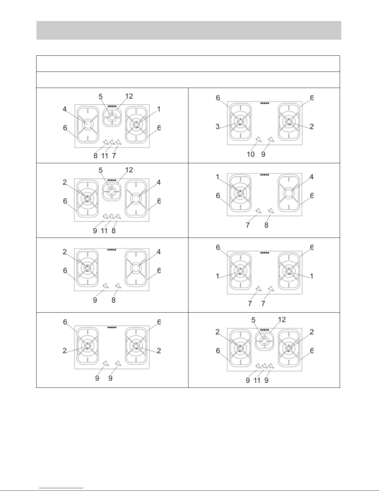
DESCRIPTION OF HOBS
78 cm.
PCZ 90 A
Page 3
3
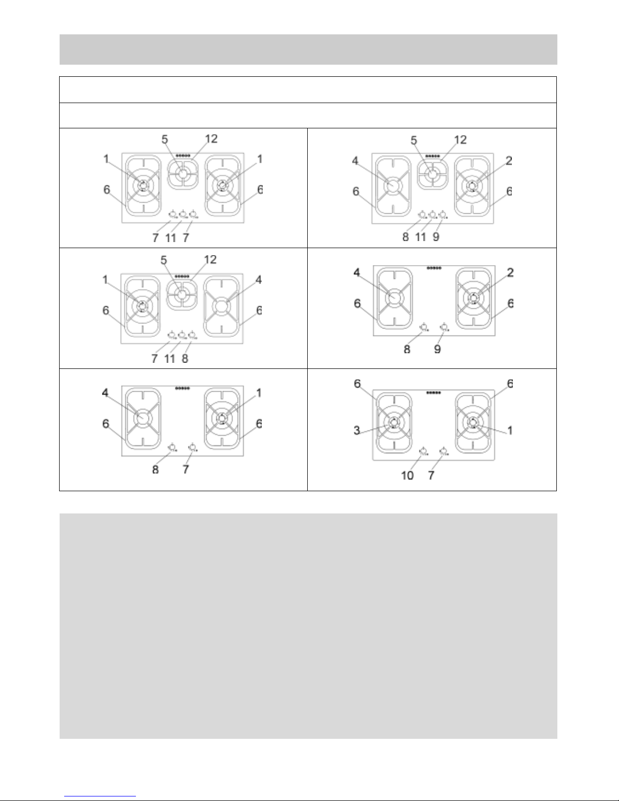
DESCRIPTION OF HOBS
78 cm.
PCZ 90 A
WARNING:
Children less than 8 years of age shall be kept away unless
continuously supervised.
This appliance can be used by children aged from 8 years and
above and persons with reduced physical, sensory or mental
capabilities or lack of experience and knowledge if they have
been given supervision or instruction concerning use of the
appliance in a safe way and understand the hazards involved.
Children shall not play with the appliance.
Cleaning and user maintenance shall not be made by children
without supervision.
Page 4
4
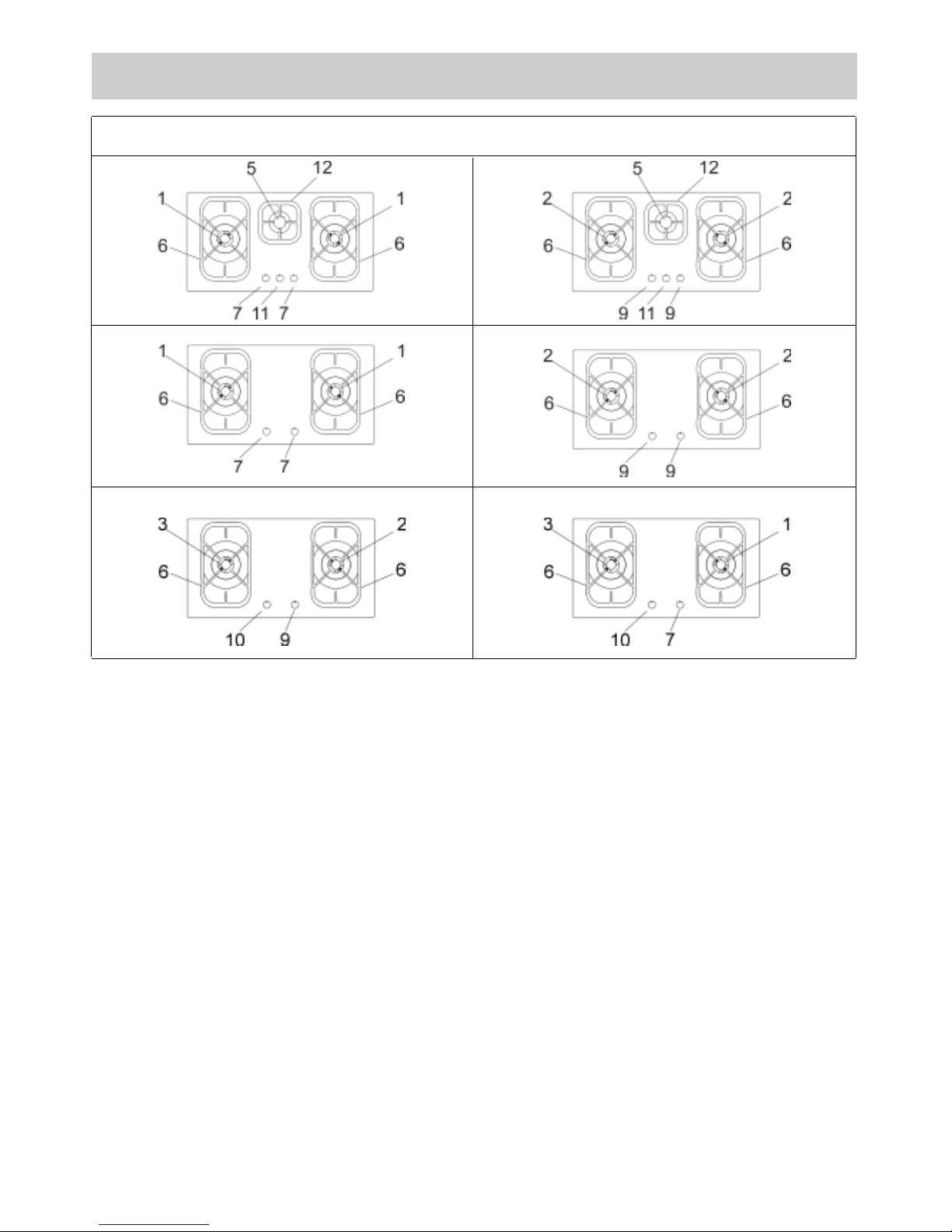
1 Double crown gas burner of 4750 ÷ 5000 W
2 Triple crown gas burner of 4000 ÷ 4500 W
3 DUAL gas burner of 4750 ÷ 5000 W
4 Semirapid gas burner of 1750 W
5 Auxiliary gas burner of 1000 W
6 Cast iron pan support lateral
7 Burner n° 1 control knob
8 Burner n° 4 control knob
9 Burner n° 2 control knob
10 Burner n° 3 control knob
11 Burner n° 5 control knob
12 Cast iron pan support central
Attention: this appliance has been manufactured for domestic use only and it employment by
private person.
PCZ 90 A 86 cm
DESCRIPTION OF HOBS
Page 5
5
USE
1) TRADITIONALS BURNERS
A diagram is screen-printed above each knob on
the front panel. This diagram indicates to which
burner the knob in question corresponds. After
having opened the gas mains or gas bottle tap, light
the burners as described below:
- automatic electrical ignition
Push and turn the knob corresponding to the
required burner in an anticlockwise direction until it
reaches the full on position (large flame fig. 1), then
depress the knob.
- Lighting burners equipped with flame failure
device
The knobs of burners equipped with flame failure
device must be turned in an anticlockwise direction
until they reach the full on position (large flame fig. 1)
and come to a stop. Now depress the knob in
qu estion and re peat th e previously indicated
operations.
Keep the knob depressed for about 10 seconds
once the burner has ignited.
In case of accidental extinguishment of the flame,
disengage the ignition by rotating the knob to the off
position. Wait at least 1 minute before re-igniting the
flame.
HOW TO USE THE BURNERS
Bear in mind the following indications in order to
achieve maximum efficiency with the least possible
gas consumption:
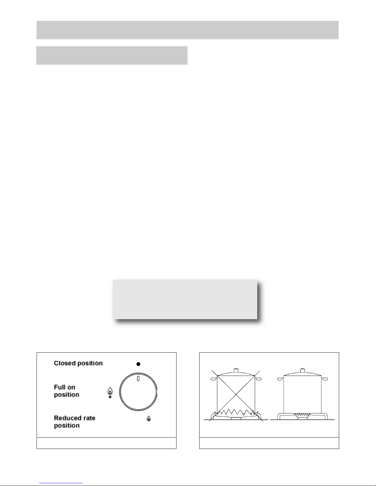
- use adequate pans for each burner (consult the
following table and fig. 2).
- When the pan comes to the boil, set the knob to
the reduced rate position (small flame fig. 1).
- Always place a lid on the pans.
- Use only pan with a flat bottom.
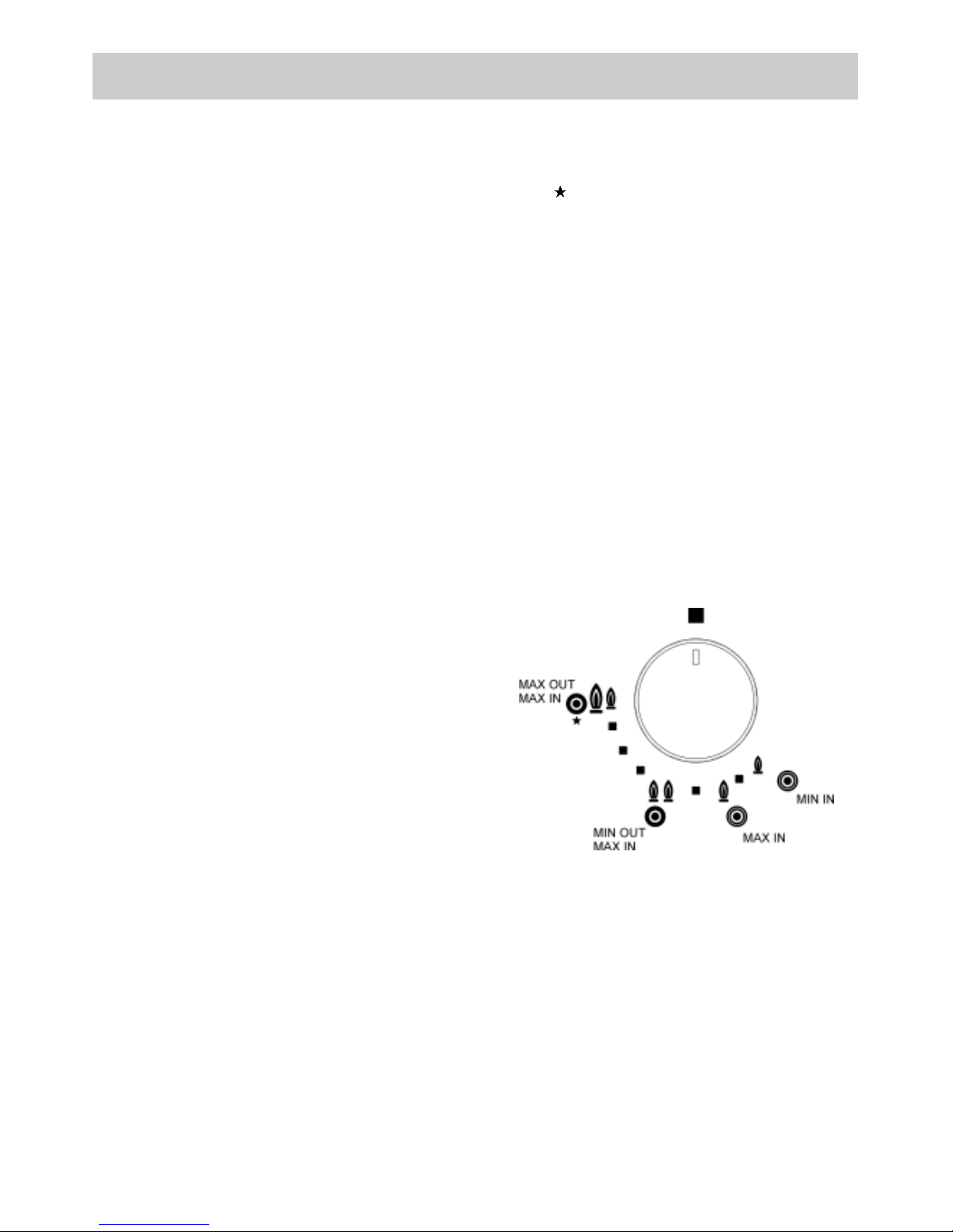
“DUAL” BURNER:
separate regulation of the inner and outer rings (in
practical terms, a dual burner controlled by a single
knob), offering very flexible use thanks to the
possibility to light either the inner flame only or the
whole burner (inner and outer flame at the same
time).
LIGHTING AND USING THE “DUAL” BURNER
Stand the pan on the burner before lighting.
Despite being controlled by a single knob, the
“DUAL” burner can be used in two different ways.
A) - Using the complete burner:
starting from the off position ● You must first press
the knob, simultaneously turning it anti-clockwise,
until the indicator points to the maximum delivery
position obtaining the maximum flow capacity of
both flames.
When the flames are lit, keep the knob pressed for
a few seconds, until the device automatically keeps
the burner lit.
It is now possible to regulate the intensity of the
flame by turning the knob anti-clockwise (from the
maximum flow capacity position of the inner and
outer flames to the maximum flow capacity of the
inner flame and the minimum of the outer flame.
To turn off the burner, turn the knob clockwise,
realigning the indicator with the ● off symbol.
B) - Using the inner flame only:
after lighting the burner and regulating the inner
flame to maximum flow capacity and the outer
flame to minimum flow capacity as described
above, turn the knob anti-clockwise until it clicks
once. The inner flame is now at maximum flow
capacity while the outer flame is turned off.
Continue turning anti-clockwise to regulate the inner
flame to the minimum flow capacity.
Turning off:
to turn off the burner, turn the knob clockwise,
realigning the indicator with the ● off symbol.
Once the “DUAL” burner is operating in either of
the two modes described, it is possible to swap
from one mode to the other by simply pressing and
turning the knob to the position required.
Page 6
6
WARNIN G: d uring oper atio n the work
surfaces of the cooking area become very
hot: keep children away!
USE
FIG. 1 FIG. 2
WARNINGS:
- matches can be used to ignite the burners in a
blackout.
- Never leave the appliance unattended when
the burners are being used. Make sure there
are no children in the near vicinity. Particularly
make sure that the pan handles are correctly
positioned and keep a check on food s
requiring oil and grease to cook since these
products can easily catch fire.
- Never use aerosols near the appliance when it
is operating.
- If the built-in hot plate has a lid, any spilt food
should be immediately removed from this
before it is opened. If the appliance has a glass
lid, this could shatter when the hot plate
becomes hot. Always switch off all the burners
before closing the lid.
- The machine must not be used by people
(including children) with impaired mental or
physical capacities, or without experience of
using electrical devices, unless supervised or
instructed by an expert adult responsible for
their care and safety. Children should not be
allowed to play with the equipment.
- Containers wider than the unit are not
recommended.
- Don't scrape the pans on the crystal because
the surface remains scratch.
Burners
Power
(W)
Ø
Pan
(cm)
complete DUAL
central DUAL
4750 ÷ 5000
900
22 ÷ 27
8 ÷ 16
Triple crown
4000 ÷ 4500
24 ÷ 26
Double crown 4750 ÷ 5000 24 ÷ 26
Semirapid 1750 16 ÷ 18
Auxiliary 1000 10 ÷ 14
Page 7
7
USE
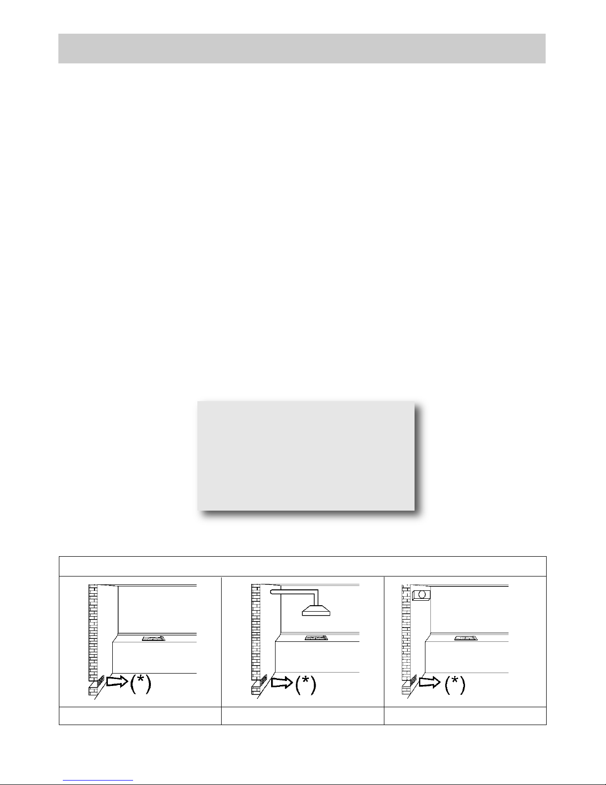
FIG. 3 FIG. 4 FIG. 5
(*) AIR INLET: SEE INSTALLATION CHAPTER (PARAGRAPHS 5 AND 6)
WARNINGS AND ADVICE FOR THE USER:
●use of a gas cooking appliance produces heat and moisture in the room in which it is installed. The
room must therefore be well ventiladed by keeping the natural air vents clear (see fig. 3) and by
activating the mechanical aeration device (suction hood or electric fan fig. 4 and fig. 5).
●
Intensive and lengthy use of the appliance may require additional ventilation. This can be achieved by
opening a window or by increasing the power of the mechanical exhausting system if installed.
●Do not attempt to change the technical characteristics of the product because it can be
dangerous.
●If you should not to use this appliance any more (or replace an old model), before disposing of it,
make it inoperative in conformity with current law on the protection of health and the prevention
of environmental pollution by making its dangerous parts harmless, especially for children who
might play on an abandoned appliance.
●Do not touch the appliance with wet or damp hands or feet.
●Do not use the appliance barefoot.
●The manufacturer will not be liable for any damage resulting from improper, incorrect or
unreasonable use.
●During, and immediately after operation, some parts of the cook top are very hot: avoid touching
them.
●After using the cook top, make sure that the knob is in the closed position and close the main
tap of the gas supply or gas cylinder.
●If the gas taps are not operating correctly, call the Customer Care Department.
CAUTION:
In case of hotplate glass breakage:
●shut immediately off all burners and any
electrical heating element and isolate
the appliance from the power supply;
●do not touch the appliance surface;
●do not use the appliance.
Page 8
8
CLEANING
IMPORTANT:
always disconnect the appliance from the gas
and electricity mains before carrying out any
cleaning operation.
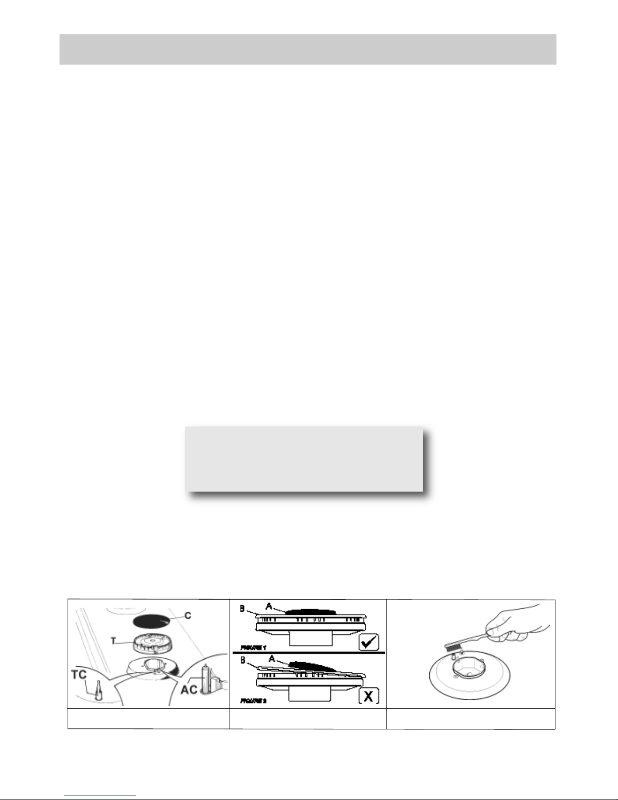
2) HOT PLATE
Periodically wash the hot plate, the enamelled stell
pan support, the enamelled burner caps “A”, “B”
and “C” and the burner heads "T" (see fig. 6 and
6/A) with lukewarm soapy water. They should also
be cleaned plugs "AC" and flame detection "TC"
(see fig. 6). Clean them gently with a small nylon
brush as shown (see fig. 6/B) and allow to dry fully.
Do not wash in the dishwasher. It is very important
to clean the surface soon after every use, when
the glass is still tepid.
Do not allow vinegar, coffee, milk, salted water,
lemon or tomato juice from remaining in contact
with the enamelled surfaces for long periods of
time. Do not clean using abrasive metal scourers,
powder abrasives or corrosive sprays.
WARNINGS:
comply with the following instructions, before
remounting the parts:
●check that burner head slots “T” (fig. 6) have
not become clogged by foreign bodies.
●Check that enamelled burner cap “A-B-C”
(fig. 6-6/A) have correctly positioned on the
burner head. It must be steady.
●Do not force the taps if they are difficult open
or close. Contact the technical assistance
service for repairs.
●Burned food on an electric plate must be
removed dry.
●After use, pour a little lukewarm oil on the
plate and wipe it with a cloth.
●The pan suppo rt must be plac ed in the
appro pri ate centering p ins verifying t he
perfect stability.
●
Corre ctl y preserve the pla te after use by
tre ating it with speci al pro ducts , easi ly
available at the supermarket. This will keep
the surface of the plate clean and bright. This
operation will also prevent the formation of
rust.
●Do n’t use ste am jets f or the equi pmen t
cleaning.
Not e: conti nuous use could ca use the
burners to change colour due to the high
temperature.
FIG. 6/B
FIG. 6/A
FIG. 6
Page 9
9
INSTALLATION
TECHNICAL INFORMATION
FOR THE INSTALLER
Instal lation, a djustme nts of control s and
maintenance must only be carried out by a
qualified engineer.
The appliance must be correctly installed in
con formi ty wit h curre nt l aw and t he
manufacturer's instructions.
Incorrec t installation may c ause damage to
persons, animals or proper ty for which the
Man ufact urer sha ll not be consid ered
responsible.
During the life of the system, the automatic
safety or regulating devices on the appliance
may only be modified by the manufacturer or
by his duly authorized dealer.
3) INSTALLING THE HOT PLATE
Check that the appliance is in a good condition after
having removed the outer packaging and internal
wrappings from around the various loose parts. In
case of doubt, do not use the appliance and contact
qualified personnel.
Never leave the packaging materials (cardboard,
bags, polystyrene foam, nails, etc.) within
children’s reach since they c ould become
potential sources of danger.
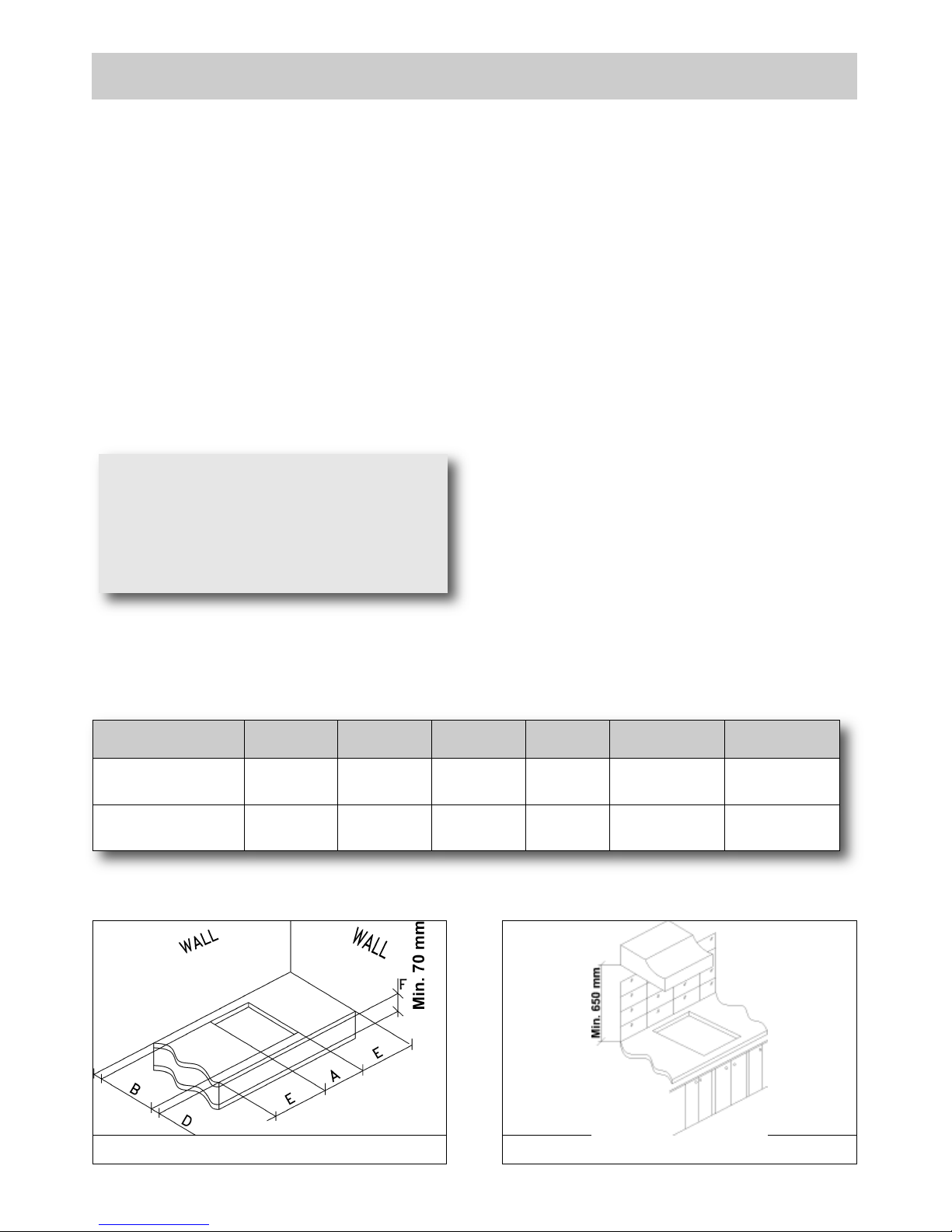
The measurements of the opening made in the top of
the modular cabinet and into which the hot plate will be
installed are indicated in either fig. 7. Always comply
with the measurements given for the hole into which
the appliance will be recessed (see fig. 7 and 8)
.
The applian ce belongs to class 3 and is
therefore subject t o all t he provisions
established by the provisions governing such
appliances.
FIG. 7 FIG. 8
COMPLY WITH THE DIMENSIONS
(in mm)
A B C D E F
2F - 3F (78) 705 405 97.5 97.5 97.5 min. 70 min.
2F - 3F (86) 705 405 97.5 97.5 97.5 min. 70 min.
IMPORTANT!
A per fect ins tall a tion , adjust ment or
transformation of the cook top to use other
gases requires a QUALIFIED INSTALLER: a
fa ilure to follo w this rule will void the
warranty.
Page 10

10
INSTALLATION
4) FIXING THE HOT PLATE
The hot plate has a special seal which prevents
liquid from getting into the cabinet. Strictly comply
with the following instructions in order to correctly
apply this seal:
- take off all the movable parts of the hob.
- Cut the seal in 4 parts of the necessary lenght to
positionning it on the 4 edges of the crystal.
- Overturn the hot plate and correctly position seal
“E” (fig. 9) under the edge of the hot plate itself,
so that the o uter side of the seal perfec tly
matches the outer edge of the hot plate. The
ends of the strips mu st fit together without
overlapping.
- Evenly and securely fix the seal to the hot plate,
pressing into place with the fingers and remove
the strip of protective paper from the seal and set
the plate into the hole made in the cabinet.
- Position the hob in the hole in the unit and fasten it in
place using the appropriate screws “F” of the
fastening hooks (fig. 10/A and 10/B).
- In o rde r to avoid a cci denta l touch with the
ove rhea ting b otto m of the h ob, during the
working, is necessary to put a wooden insert,
fixed by screws, at a minimum di stance of
70 mm from the top (see fig. 7).
FIG. 9
FIG. 10/A FIG. 10/B
CAUTION:
do not place the glass directly on the unit.
The bott om of the hob must rest on
the unit.
FIG. 10/C
Caution: Do not allow the glass (A)
lay directly on the work top. it is the
bottomshelf (B) that has to be in
tou ch w ith the wor k t op ( see
fig. 10/C).
Page 11

11
IMPORTANT INSTALLATION
SPECIFICATIONS
The installer should note that the appliance that
side walls should be no higher than the hot plate
itself. Furthermore, the rear wall, the surfaces
surrounding and adjacent to the appliance must
be able to withstand an temperature of 90 °C.
The adhesive used to stick the plastic laminate to
the cabinet must be able to withstand a
temperature of not less than 150 °C otherwise the
laminate could come unstuck.
The appliance must be installed in compliance
with the provisions in force.
This appliance is not connected to a device able
to dispose of the combustion fumes. It must
therefore be connected in compliance with the
above mentioned installation standards.
Particular care should be paid to the following
provisions governing ventilation and aeration.
5) ROOM VENTILATION
It is essential to ensure that the room in which the
appliance is installed is permanently ventilated in
order to allow the appliance itself to operate correctly.
the necessary amount of air is that required for
regular gas combustion and ventilation of the relative
room, the volume of which must not be less than 20
m3. Air must naturally flow through permanent
openings in the walls of the room in question. These
openings must vent the fumes outdoors and their
section must be at least 100 cm2(see fig. 3).
Construction of the openings must ensure that the
openings themselves may never be blocked. Indirect
ventilation by air drawn from an adjacent room is also
permitted, in strict compliance with the provisions in
force.
CAUTION: if the burners of the cooking top are
without safety thermocouple, the ventilation
outlet must have a minimum 200 cm² section.
6) LOCATION AND AERATION
Gas cooking appliances must always dispose of
their combustion fumes through hoods. These
must be connected to flues, chimneys or straight
outside. If it is not possible to install a hood, an
electric fan can be installed on a window or on a
wall facing outside (see fig. 4). This must be
activated at the same time as the appliance (see
fig . 5 ) , s o l ong as the spec ific a tion s i n t he
provisions in force are strictly complied with.
7) GAS CONNECTION
Before connecting the appliance, check that
the values on the data label affixed to the
underside of the hot plate correspond to those
of the gas and electricity mains in the home.
A labe l on the appli ance indi cates the
regulating conditions: type of gas and working
pressure. Gas connection must comply with
th e pertinent standards an d provisions in
force.
When gas is supplied through ducts, the appliance
must be connected to the gas supply system:
● with a rigid steel pipe. The joints of this pipe must
consist of threaded fittings conforming to the
standards.
● With copper pipe. The joints of this pipe must
consist of unions with mechanical seals.
● With seamless flexible stainless steel pipe. The
length of this pipe must be 2 meters at most and
the seals must comply with the standards.
When the gas is supplied by a bottle, the appliance
must be fuelled by a pressure governor conforming to
the provisions in force and must be connected:
● with a copper pipe. The joints of this pipe must
consist of unions with mechanical seals.
● With seamless flexible stainless steel pipe. The
length of this pipe must be 2 meters at most and
the seals must comply with the standards. It is
advisable to apply the special adapter to the flexible
pipe. This is easily available from the shops and
facilitates connection with the hose nipple of the
pressure governor on the bottle.
● With rubber hose pipe in compliance with
standards. The diameter of this hose pipe must be
8 mm and its length must be no less than 400 mm
and no more than 1500 mm. It must be firmly fixed
to the hose nipple by means of the safety clamp
specified by standards.
WARNINGS:
remember that the gas inlet union on the
appliance is a 1/2" gas parallel male type in
compliance with ISO 228-1 standards.
Installation of stainless steel pipe and rubber
hose pipe must ensure that it is never able to
touch mobile parts of the built-in cabinet (eg.
drawers). Furthermore, it must not pass through
compartments that could be used for storage
purposes.
When using a rubber hose pipe, it is essential to
comply with the following instructions:
- no part of the pipe must be able to touch parts
the temperature of which exceeds 90 ° C.
- The pipe must not be pulled or twisted, throttled
or tughtly bent.
- It must not come into contact with sharp edges
or corners.
- It must be easy to inspect the entire pipe length
in order to check its state of wear.
- The pipe must be replaced within the date
stamped on the pipe itself.
- The appliance complies with the provisions of
the following CEE Directives:
CEE 2009/142 regarding gas safety.
INSTALLATION
Page 12

12
INSTALLATION
8) ELECTRICAL CONNECTION
The electrical connections of the appliance
must be carried out in compliance with the
provisions and standards in force.
Before connecting the appliance, check that:
- the voltage matches the value shown on the
specification plate and the section of the wires of
the electrical system can support the load, which
is also indicated on the specification plate.
- The electrical capacity of the mains supply
a n d c u r r e n t soc k e t s su i t t h e max i m u m
power rating of the appliance (consu lt the
data label app lie d to the underside o f the
hot plate).
- The socket or system has an efficient earth
connection in compliance with the provisions and
standards in force. The manufacturer declines all
responsibility for failing to comply with these
provisions.
When the app lia nce is connec ted to the
electricity main by a socket:
- fit a standard plug “C” suited to the load indicated
on the data label to the cable. Fit the wires
following figure 11, taking care of respecting the
following correspondences:
Letter L (live) = brown wire;
Letter N (neutral) = blue wire;
earth symbol = green - yellow wire.
- The power supply cable must be positioned so
that no part of it is able to reach an temperature of
90 °C.
- Never use reductions, adapters of shunts for
connection since these could create false contacts
and lead to dangerous overheating.
- The outlet must be accessible after the built-in.
When the appliance is connected straight to the
electricity main:
- install an omnipolar circuit-breaker between the
appliance and the electricity main. This circuitbreaker should be sized, in compliance with
current installation regulations.
- Remem ber tha t the earth w ire must not be
interrupted by the circuit-breaker.
- For optimum safety, the electrical connection may
also be protected by a high sensitivity differential
circuit- breaker.
You are strongly advised to fix the relative yellowgreen earth wire to an efficient earthing system.
Before performing any service on the electrical
part of the appliance, it must absolutely be
disconnected from the electrical network.
WARNINGS:
all our products are conform with the
European Norms and relative amendments.
The product is therefore conform with the
requirements of the European Directivesin
force relating to:
- compatibility electromagnetic (EMC);
- electrical security (LVD);
- restriction of use of certain hazardous
substances (RoHS);
- EcoDesign (ERP).
IMP ORTANT: the app l ianc e mu st b e
in stalled fo llowing the manufacturer 's
instructions. The manufacturer will not be
liable for injury to persons or animals or
property damage caused by an incorrect
installation.
If the installation requires modifications to
the hom e's e lectrical system or if the
socket is incompatible with the appliance's
plu g , have ch ange s or repla ceme nts
perfo rme d by professionally -qu alified
person. In particular, this person must also
make sure that the section of the wires of
the soc ket is suit able for the po w er
absorbed by the appliance.
FIG. 11
Page 13

13
9) INSTALLING THE HOT PLATE
WITH THE BATTERY
Check that the appliance is in a good condition after
having removed the outer packaging and internal
wrappings from around the various loose parts. In
case of doubt, do not use the appliance and contact
qualified personnel.
Never leave the packaging materials
(cardboard, bags, polystyrene foam, nails, etc.)
within chil dren’s reach since the y could
become potential sources of danger.
The measurements of the opening made in the top
of the modular cabinet and into which the hot plate
will be installed are indicated in either fig. 7.
Always comply with the measurements given for
the hole into which the appliance will be recessed
(see fig. 7 and 8).
The appliance be lon gs t o cla ss 3 and i s
therefore subject to all the pro vis ions
established by the provisions governing such
appliances.
10) FIXING THE HOT PLATE
The hot plate has a special seal which prevents
liquid from infiltrating into the cabinet. Strictly
comply with the following instructions in order to
correctly apply this seal:
- take off all the movable parts of the hob.
- Detach the seals from their backing, checking
that the transparent protection still adheres to the
seal itself.
- Overturn the hot plate and correctly position seal
“E” (fig. 9) under the edge of the hot plate itself,
so t hat the outer s ide of th e seal perfe ctly
matches the outer perimetral edge of the hot
plate. The ends of the strips must fit together
without overlapping.
- Unscrew the ignition cap “T” (see fig. 12) and fit
a 1.5 V battery (not included in the appliance)
with the positive “+” polarity turn inside. Rescrew
the cap.
- Evenly and securely fix the seal to the hob lower
part, pressing it in place with the fingers, remove
the strip of protective paper from the seal. Fit the
hob into the hole in the cabinet.
- Position the hob in the hole in the unit and fasten
it in place using the appropriate screws “F” of the
fastening hooks (see fig. 10/A and 10/B).
- In order to avoid acc idental t ouch with th e
ove rhea tin g bott om of the hob , duri ng the
working, is necessary to put a wooden insert,
fixed by screws, at a minimum distance of 70
mm from the top (see fig. 7).
Remark: below is the suggested clearances.
Actual installation will be veried subject to different
kitchen situations.
INSTALLATION
FIG. 12
Page 14

14
ADJUSTMENTS
FIG. 13/A
Always disconnect the appliance from the
electricity main before making any adjustments.
All seals must be replaced by the technician at
the end of any adjustments or regulations.
Our burners do not re qui re pri mary a ir
adjustment.
11) TAPS
“Reduced rate” adjustment
- Switch on the burner and turn the relative knob to
the “Reduced rate” position (small flame fig. 1).
- Remove knob “M” (fig. 13 and 13/A) of the tap,
which is simply pressed on to its rod. The by-pass
for minimal rate regulation can be: beside the tap
(fig. 13) or inside the shaft. In any case, to access
to regulation, it can be done trought the insertion
of a small screwdriver ‘’D’’ beside the tap (fig. 13)
or in the hole ‘’C’’ inside the shaft of the tap
(fig 13/A). Turn the throttle screw to the right or left
un til th e burner flame has been ad equately
regulated to the “Reduced rate” position.
The flame should not be too low: the lowest small
flame sho uld be conti nuous and steady. Reassemble the several components.
It is understood that only burners operating
with Town gas should be subjected to the
above mentioned adjustments. T he screw
must be fully locked when the burners operate
wit h (LP G) L iquid Pet roleu m Gas (tu rn
clockwise).
The operations described above can be carried out
easily, whatever the position of the hob or however
it is fastened to the unit.
FIG. 13
WARNING:
To adjust the minimum “DUAL” burner first
remove the bushing “E” (fig. 13).
In t he case of a “DUAL” bur ner, th e
regulation screw situated inside the post of
the valve regulates the central flame, while
the screw next to the valve regulates the
outer flame.
Page 15

15
CONVERSIONS
12) REPLACING THE INJECTORS
The burners can be adapted to different types of
gas by mounting injectors suited to the type of gas
in question. To do this, first remove the burner tops
using a wrench “B”. Now unscrew injector “A” (see
fig. 14) and fit a injector corresponding to the
utilized type of gas in its place.
It is advisable to strongly tighten the injector in
place.
After the injectors have been replaced, the
burners must be regulated as explained in
paragraphs 11. The technician must reset any
seals on the regu lating or pre-re gulatin g
devices.
The envelope with the injectors and the labels
can be included in the kit, or at disposal to the
authorized customer Service Centre.
For the sake of convenience, the nominal rate
table also lists the heat inputs of the burners, the
dia m eter of the inje ctors and t h e wor king
pressures of the various types of gas.
BURNERS ARRANGEMENT ON THE HOT PLATE
78 cm.
Page 16

16
CONVERSIONS
86 cm.
TABLE
BURNERS
GAS
WORKING
PRESSURE
mbar
HEAT
CAPACITY
NOZZLE
DIAMETER
1/100 mm
HEAT
CAPACITY (W)
No.
Description
gr/h l/h Min. Max.
3
DUAL total **
G30 - BUTANE
G31 - PROPANE
G20 - NATURAL
28-30
37
20
345
339
476
2 x 72B + 46B
2 x 72B + 46B
2 x 115A + 71A
2700
2700
2700
4750
4750
5000
DUAL central
G30 - BUTANE
G31 - PROPANE
G20 - NATURAL
28-30
37
20
65
64
86
46B
46B
71A
300
300
300
800
800
900
1
DOUBLE
CROWN
G30 - BUTANE
G31 - PROPANE
G20 - NATURAL
28-30
37
20
345
339
476
2 x 72B + 46B
2 x 72B + 46B
2 x 115A + 71A
2700
2700
2700
4750
4750
5000
2
TRIPLE
CROWN
G30 - BUTANE
G31 - PROPANE
G20 - NATURAL
28-30
37
20
291
286
381
100B
100B
145A
1500
1500
1500
4000
4000
4000
4
SEMIRAPID
G30 - BUTANE
G31 - PROPANE
G20 - NATURAL
28-30
37
20
127
125
167
68
68
98Z
550
550
550
1750
1750
1750
5
AUXILIARY
G30 - BUTANE
G31 - PROPANE
G20 - NATURAL
28-30
37
20
73
71
95
51
51
75X
450
450
450
1000
1000
1000
BURNERS ARRANGEMENT ON THE HOT PLATE
FIG. 14
**Mount with bushing (B) if present (see Fig. 14/A).
Page 17

17
FIG. 17 FIG. 18
FIG. 15 FIG. 16
SERVICING
Always disconnect the appliance from the
electricity and gas mains before proceeding
with any servicing operation.
13) REPLACING HOT PLATE PARTS
When parts housed within the hot plate need
replacing, it is first necessary to remove the hot
plate itself from the cabinet.
Aft er h avin g car ried out the abov e li sted
operations, the burners (fig. 15), taps (fig. 16) and
electrical components can all be replaced (fig. 17).
It is advi sable to c hang e sea l "D" (fig. 1 6)
whenever a tap is replaced to ensure a perfect
tightness.
Greasing the taps (see fig. 18)
If a tap b eco mes stiff to operate, it m ust be
immediately g reased in com pli ance with the
following instructions:
- remove the tap.
- Clean the cone and its housing using a cloth
soaked in diluent.
- Lightly spread the cone with the relative grease.
- Fit the cone back in place, operate it several times
and then remove it again. Eliminate any excess
grease and check that the gas ducts have not
become clogged.
- Fit all parts back in place, complying with the
demounting order in reverse.
- The tight closure test must be done using a foamy
liquid. The use of the flame is prohibited.
To facilitate the servicing technician’s task, here is a
chart with the types and sections of the powering
cables and the ratings of the electrical components.
WARNING: MAINTENANCE MUST ONLY BE
PERFORMED BY AUTHORISED PERSONS.
FIG. 14/A
Page 18

18
SERVICING
14) REPLACING THE BATTERY
To change the battery (see fig. 19) comply with
following instructions:
- unscrew cap “T” and remove exausty battery.
- Insert a 1.5 V new battery. The positive polarity
“+” is turn over inside.
- Rescrew the cap “T”.
- Re-assembly all the movable parts.
WARNING:
the batteries contain a dangerous material for
our ambient. Always put them in a separate
and safe container.
If you eliminate your appliance, remember to
take off the battery.
FIG. 19
IMPORTANT: The bat ter y can b e
rechargeable or not rechargeable.
The rechargeable battery shall be removed
from appliance before being recharged.
Do not att emp t t o recharge the not
rechargeable batteries.
The power supply poles shall not be short
circuited.
Page 19
19
FIG. 20
SERVICING
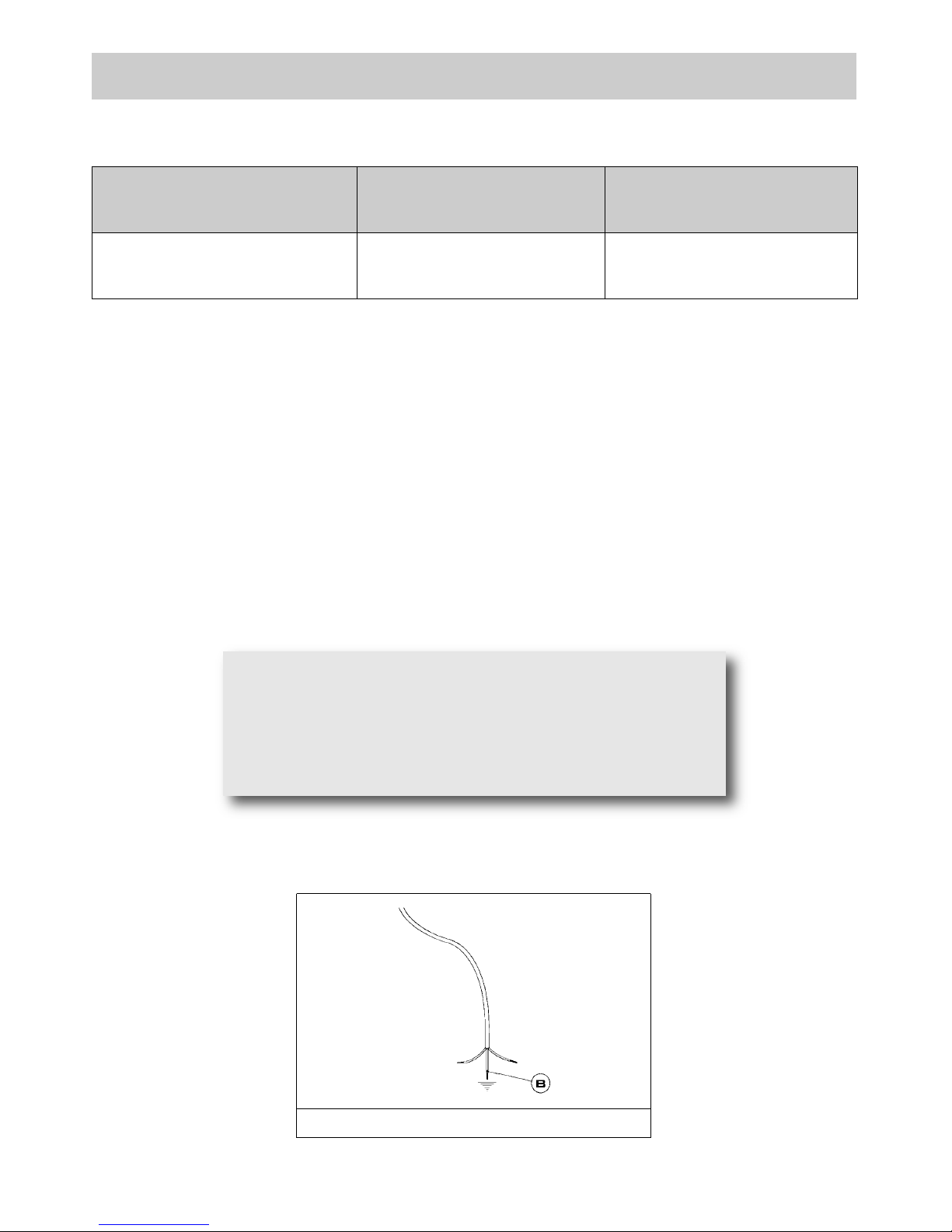
CABLE TYPES AND SECTIONS
ATTENTION!!!
If the power supply cable is replaced, the installer should leave the ground wire (B) longer than the
phase conductors (fig. 20) and comply with the recommendations given in paragraph 8.
TYPE OF
HOT PLATE
TYPE OF
CABLE
SINGLE - PHASE
POWER SUPPLY
Gas hot plate H05 RR - F Section 3 x 0.75 mm
2
In case of failure or cut in the cable, please move
away from the cable and do not touch it. Moreover
the device must be unplugged and not switched on.
Call the nearest authorized service center to fix the
problem.
Page 20
20
TECHNICAL DATA ON THE DATA LABEL
2 BURNERS
(DUAL sx - Triple crown dx)
BUTANE = 28-30 mbar
PROPANE = 37mbar
NATURAL = 20 mbar
Σ Qn Butane Gas Rate
= 9.5 kW
Σ QnNatural Gas Rate = 10.0 kW
Σ Qn Butane Gas Rate = 691 gr/h
Voltage = 220-240 V ~
Frequency = 50/60 Hz
If with battery:
Voltage = 1.5 V
2 BURNERS
(Double crown sx dx)
BUTANE = 28-30 mbar
PROPANE = 37mbar
NATURAL = 20 mbar
Σ Qn Butane Gas Rate
= 9.5 kW
Σ QnNatural Gas Rate = 10.0 kW
Σ Qn Butane Gas Rate = 691
gr/h
Voltage = 220-240 V ~
Frequency = 50/60 Hz
If with battery:
Voltage = 1.5 V
2 BURNERS
(Double crown sx - SR dx)
BUTANE = 28-30 mbar
PROPANE = 37mbar
NATURAL = 20 mbar
Σ Qn Butane Gas Rate
= 6.5 kW
Σ QnNatural Gas Rate = 6.75 kW
Σ Qn Butane Gas Rate = 491 gr/h
Voltage = 220-240V ~
Frequency = 50/60 Hz
If with battery:
Voltage = 1.5 V
2 BURNERS
(Triple crown sx dx)
BUTANE = 28-30 mbar
PROPANE = 37mbar
NATURAL = 20 mbar
Σ Qn Butane Gas Rate
= 8.0 kW
Σ QnNatural Gas Rate = 8.0 kW
Σ Qn Butane Gas Rate = 582 gr/h
Voltage = 220-240 V ~
Frequency = 50/60 Hz
If with battery:
Voltage = 1.5 V
2 BURNERS
(Triple crown sx - SR dx)
BUTANE = 28-30 mbar
PROPANE = 37mbar
NATURAL = 20 mbar
Σ Qn Butane Gas Rate
= 5.75 kW
Σ QnNatural Gas Rate = 5.75 kW
Σ Qn Butane Gas Rate = 418 gr/h
Voltage = 220-240 V ~
Frequency = 50/60 Hz
If with battery:
Voltage = 1.5 V
3 BURNERS
(Double crown sx dx
- Aux. central)
BUTANE = 28-30 mbar
PROPANE = 37mbar
NATURAL = 20 mbar
Σ Qn Butane Gas Rate
= 10.5 kW
Σ QnNatural Gas Rate = 11.0 kW
Σ Qn Butane Gas Rate = 763 gr/h
Voltage = 220-240 V ~
Frequency = 50/60 Hz
If with battery:
Voltage = 1.5 V
2 BURNERS
(2 DUAL)
BUTANE = 28-30 mbar
PROPANE = 37mbar
NATURAL = 20 mbar
Σ Qn Butane Gas Rate
= 9.5 kW
Σ QnNatural Gas Rate = 10 kW
Σ Qn Butane Gas Rate = 691
gr/h
Voltage = 220-240 V ~
Frequency = 50/60 Hz
If with battery:
Voltage = 1.5 V
3 BURNERS
(2 DUAL + Aux. central)
BUTANE = 28-30 mbar
PROPANE = 37mbar
NATURAL = 20 mbar
Σ Qn Butane Gas Rate
= 10.5 kW
Σ QnNatural Gas Rate = 11.0 kW
Σ Qn Butane Gas Rate = 763 gr/h
Voltage = 220-240 V ~
Frequency = 50/60 Hz
If with battery:
Voltage = 1.5 V
78 cm.
Page 21

21
TECHNICAL DATA ON THE DATA LABEL
3 BURNERS
(Triple crown dx - SR sx
Aux. central)
BUTANE = 28-30 mbar
PROPANE = 37mbar
NATURAL = 20 mbar
Σ Qn Butane Gas Rate
= 6.75 kW
Σ QnNatural Gas Rate = 6.75 kW
Σ Qn Butane Gas Rate = 491 gr/h
Voltage = 220-240 V ~
Frequency = 50/60 Hz
If with battery:
Voltage = 1.5 V
3 BURNERS
(Double crown sx - SR dx
Aux. central)
BUTANE = 28-30 mbar
PROPANE = 37mbar
NATURAL = 20 mbar
Σ Qn Butane Gas Rate
= 7.5 kW
Σ QnNatural Gas Rate = 7.75 kW
Σ QnButane Gas Rate = 545 gr/h
Voltage = 220-240 V ~
Frequency = 50/60 Hz
If with battery:
Voltage = 1.5 V
3 BURNERS
(Double crown dx - SR sx
Aux. central)
BUTANE = 28-30 mbar
PROPANE = 37mbar
NATURAL = 20 mbar
Σ Qn Butane Gas Rate
=7.5
kW
Σ QnNatural Gas Rate = 7.75 kW
Σ QnButane Gas Rate = 545 gr/h
Voltage = 220-240 V ~
Frequency = 50/60 Hz
If with battery:
Voltage = 1.5 V
3 BURNERS
(Triple crown sx dx
- Aux. central)
BUTANE = 28-30 mbar
PROPANE = 37mbar
NATURAL = 20 mbar
Σ Qn Butane Gas Rate
= 9.0
kW
Σ QnNatural Gas Rate = 9.0 kW
Σ QnButane Gas Rate = 654 gr/h
Voltage = 220-240 V ~
Frequency = 50/60 Hz
If with battery:
Voltage = 1.5 V
3 BURNERS
(Triple crown sx - SR dx
Aux. central)
BUTANE = 28-30 mbar
PROPANE = 37mbar
NATURAL = 20 mbar
Σ Qn Butane Gas Rate
= 6.75
kW
Σ QnNatural Gas Rate = 6.75 kW
Σ Qn Butane Gas Rate = 491 gr/h
Voltage = 220-240 V ~
Frequency = 50/60 Hz
If with battery:
Voltage = 1.5 V
2 BURNERS
(SR sx - TC dx)
BUTANE = 28-30 mbar
PROPANE = 37mbar
NATURAL = 20 mbar
Σ Qn Butane Gas Rate
= 5.75
kW
Σ QnNatural Gas Rate = 5.75 kW
Σ Qn Butane Gas Rate = 418 gr/h
Voltage = 220-240 V ~
Frequency = 50/60 Hz
If with battery:
Voltage = 1.5 V
2 BURNERS
(SR sx - DC dx)
BUTANE = 28-30 mbar
PROPANE = 37mbar
NATURAL = 20 mbar
Σ Qn Butane Gas Rate
= 6.5
kW
Σ QnNatural Gas Rate = 6.75 kW
Σ Qn Butane Gas Rate = 491gr/h
Voltage = 220-240 V ~
Frequency = 50/60 Hz
If with battery:
Voltage = 1.5 V
2 BURNERS
(DUAL sx - DC dx)
BUTANE = 28-30 mbar
PROPANE = 37mbar
NATURAL = 20 mbar
Σ Qn Butane Gas Rate
= 9.5
kW
Σ QnNatural Gas Rate = 10.0 kW
Σ Qn Butane Gas Rate = 691 gr/h
Voltage = 220-240 V ~
Frequency = 50/60 Hz
If with battery:
Voltage = 1.5 V
78 cm.
Page 22
22
TECHNICAL DATA ON THE DATA LABEL
86 cm.
2 BURNERS
(Double crown sx dx)
BUTANE = 28-30 mbar
PROPANE = 37mbar
NATURAL = 20 mbar
Σ Qn Butane Gas Rate
= 9.5
kW
Σ QnNatural Gas Rate = 10.0 kW
Σ Qn Butane Gas Rate = 691 gr/h
Voltage = 220-240 V ~
Frequency = 50/60 Hz
If with battery:
Voltage = 1.5 V
2 BURNERS
(Triple crown sx dx)
BUTANE = 28-30 mbar
PROPANE = 37mbar
NATURAL = 20 mbar
Σ Qn Butane Gas Rate
= 8.0
kW
Σ QnNatural Gas Rate = 8.0 kW
Σ Qn Butane Gas Rate = 582 gr/h
Voltage = 220-240 V ~
Frequency = 50/60 Hz
If with battery:
Voltage = 1.5 V
3 BURNERS
(Triple crown sx dx
- Aux. central)
BUTANE = 28-30 mbar
PROPANE = 37mbar
NATURAL = 20 mbar
Σ Qn Butane Gas Rate
= 9.0
kW
Σ QnNatural Gas Rate = 9.0 kW
Σ Qn Butane Gas Rate = 691 gr/h
Voltage = 220-240 V ~
Frequency = 50/60 Hz
If with battery:
Voltage = 1.5 V
3 BURNERS
(Double crown sx dx
- Aux. central)
BUTANE = 28-30 mbar
PROPANE = 37mbar
NATURAL = 20 mbar
Σ Qn Butane Gas Rate
= 10.5
kW
Σ QnNatural Gas Rate = 11.0 kW
Σ Qn Butane Gas Rate = 763 gr/h
Voltage = 220-240 V ~
Frequency = 50/60 Hz
If with battery:
Voltage = 1.5 V
2 BURNERS
(DUAL sx - TC dx)
BUTANE = 28-30 mbar
PROPANE = 37mbar
NATURAL = 20 mbar
Σ Qn Butane Gas Rate
= 8.75
kW
Σ QnNatural Gas Rate = 9.0 kW
Σ Qn Butane Gas Rate = 636 gr/h
Voltage = 220-240 V ~
Frequency = 50/60 Hz
If with battery:
Voltage = 1.5 V
2 BURNERS
(DUAL sx - DC dx)
BUTANE = 28-30 mbar
PROPANE = 37mbar
NATURAL = 20 mbar
Σ Qn Butane Gas Rate
= 9.5
kW
Σ QnNatural Gas Rate = 10.0 kW
Σ Qn Butane Gas Rate = 691 gr/h
Voltage = 220-240 V ~
Frequency = 50/60 Hz
If with battery:
Voltage = 1.5 V
2 BURNERS
(2 DUAL)
BUTANE = 28-30 mbar
PROPANE = 37mbar
NATURAL = 20 mbar
Σ Qn Butane Gas Rate
= 9.5
kW
Σ QnNatural Gas Rate = 10.0 kW
Σ Qn Butane Gas Rate = 691 gr/h
Voltage = 220-240 V ~
Frequency = 50/60 Hz
If with battery:
Voltage = 1.5 V
3 BURNERS
(2 DUAL- Aux central)
BUTANE = 28-30 mbar
PROPANE = 37mbar
NATURAL = 20 mbar
Σ Qn Butane Gas Rate
= 10.5
kW
Σ QnNatural Gas Rate = 11.0 kW
Σ Qn Butane Gas Rate = 763 gr/h
Voltage = 220-240 V ~
Frequency = 50/60 Hz
If with battery:
Voltage = 1.5 V
Page 23

23
TECHNICAL DATA FOR THE
APPLIANCE GAS REGULATION
Page 24

24
Before leaving the factory, this appliance will have been tested and regulated by expert and specialized
personnel in order to guarantee the best performances.
Any repairs or adjustments which may be subsequently required may only be carried out by qualified
personnel with the utmost care and attention.
For this reason, always contact your Dealer or our nearest After Sales Service Center whenever repairs
or adjustments are required, specifying the type of fault and the model of the appliance in your
possession.
Please also note that genuine spare parts are only available from our After Sales Service Centers and
authorized retail outlets.
The above data are printed on the data label put on the inferior part of the appliance and on the packing
label.
The above informations give to the technical assistant the possibility to get fit spare parts and a heavensent intervention. We suggest to fill the table below.
MARK: ........................................................................
MODEL: ......................................................................
SERIES: ......................................................................
TECHNICAL ASSISTANCE AND SPARE PARTS
This appliance is marked according to the European directive 2002/96/EC on
Waste Electrical and Electronic Equipment (WEEE).
This guideline is the frame of a European-wide validity of return and recycling on
Waste Electrical and Electronic Equipment.
 Loading...