

Page 1
INSTALLATION AND USER INSTRUCTIONS
BUILT-IN CERAMIC HOB
C04-M1
COD. 208822-00 - 16.11.2016
Dear Customer,
We thank you and congratulate you on granting us your preference, by purchasin one of our products.
We are sure that this new appliance, manufactured with quality materials, will meet your requirements in
the best possible way.
The use of this new equipment is easy. However, we invite you to read this booklet carefully, before
installing and using the appliance. This booklet gives the right information on the installation, use and
maintenance, as well asuseful advice.
THE MANUFACTURER
London
Page 2

2
GENERAL NOTICE
WARNING:
• The appliance and its accessible parts become
hot during use. Care should be taken to avoid
touching heating elements. Children less than
8 years of age shall be kept away unless
continuously supervised.
• This appliance can be used by children aged from
8 years and above and persons with reduced
physical, sensory or mental capabilities or lack
of experience and knowledge if they have been
given supervision or instruction concerning use of
the appliance in a safe way and understand the
hazards involved. Children shall not play with the
appliance. Cleaning and user maintenance shall
not be made by children without supervision.
• Unattended cooking on a hob with fat or oil can
be dangerous and may result in fire. NEVER try
to extinguish a fire with water, but switch off the
appliance and then cover flame e.g. with a lid or a
fire blanket.
• Danger of fire: do not store items on the cooking
surfaces.
• If the surface is cracked, switch off the appliance
to avoid the possibility of electric shock.
• The appliance is not intended to be operated by
means of an external timer or separate remotecontrol system.
Page 3

3
GENERAL NOTICE
• Don’t use a steam cleaner for the cleaning the
hob.
Page 4
44
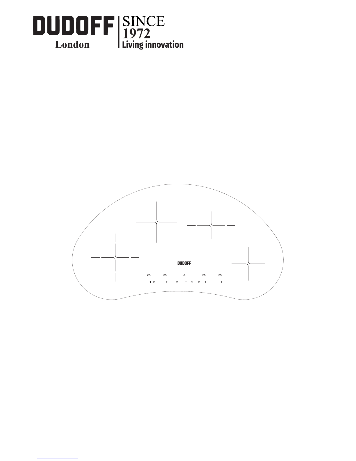
DESCRIPTION
1
3
2
3
DESCRIPTION
1 - Hi-light heating Ø 145 1,2 kW
2 - Hi-light heating Ø 180 1,8 kW
3 - 2 circuit hi-light heating Ø 210/120 2,2/0,75 kW
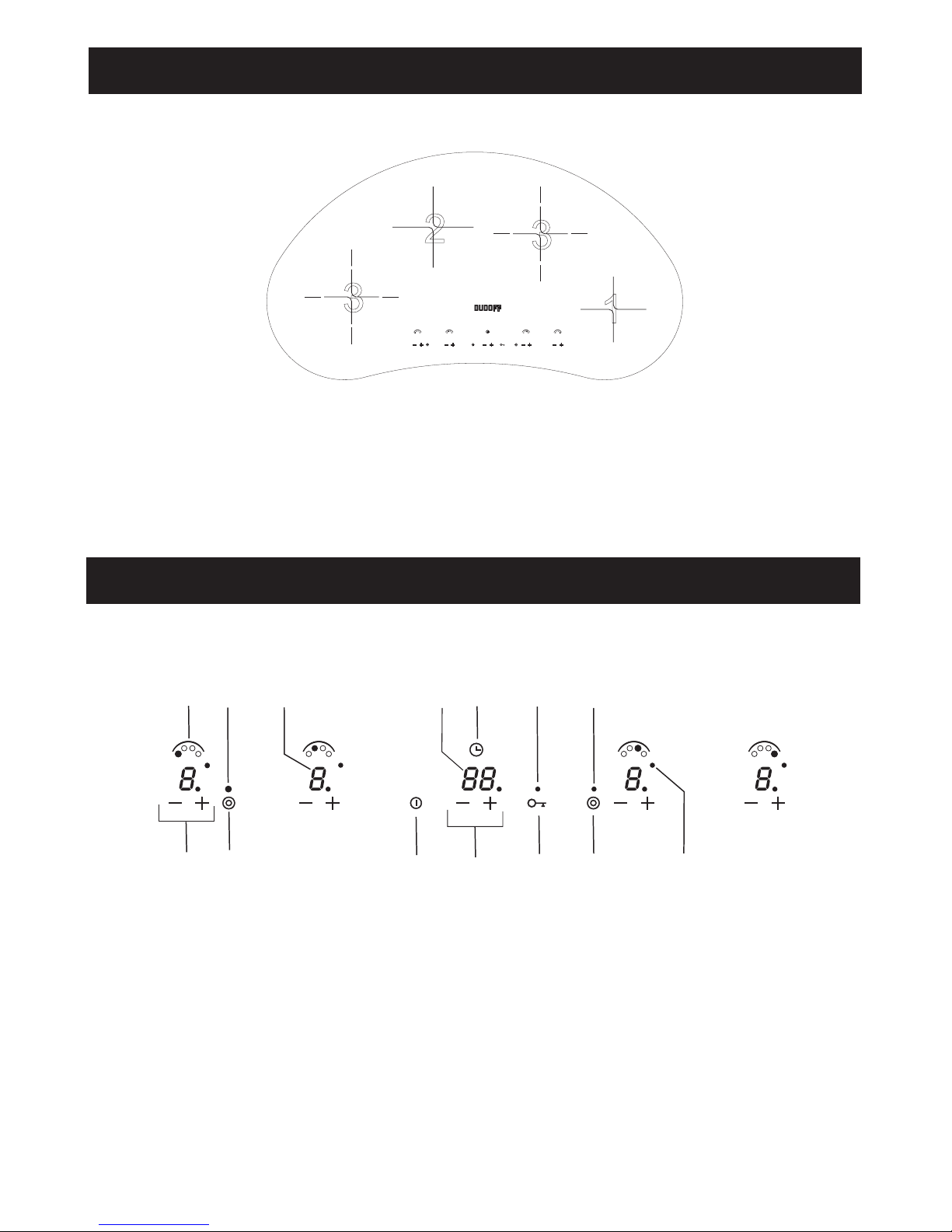
TOUCH CONTROL
2
1
4
3
5
6 8 10
12
7
9
11
13
14
1 Selection of cooking setting 8 Selection of timer setting
2 Cooking setting position 9 Timer position
3 Connection key front left 10 Locking of the cooking surface connection
and selection
4 Connection display front left 11 Locking display
5 Display of cooking setting 12 Connection key rear right
6 On/Off switch, emergency off switch 13 Connection display rear right
7 Display timer 14 Connection display timer
London
Page 5

5
INSTRUCTION FOR THE USER
NOTICE
• Use only flat pans and with sufficiently thick base,
equal or not much superior that the hot plate
(fig.1).
• The containers should not have rough bottoms in
order to avoid scratching the heat surface of the
top.
• Do not switch the electric plate without the pan
over the plate.
• Do not cook any food on the hot area.
• Avoid overflows of liquid.
• Turn off the plate few minutes before the cooking
end.
USE
Switching on
The control is switched on by pressing the On/Off
key (key 6) for 1 second, causing a sound signal;
it will not turn on while the Key Lock function (key
10) is active (indicated by a LED) (Led 11).
The heating elements remain switched off (all the
digits at 0) until a power level is selected. If this is
not done with in 10 seconds the control switches
off automatically.
Selecting the cooking level
With the control turned on, the first time that the (+)
sensor (key 1) is touched the heating element is
turned on to the present level (in EEPROM).
The (+) sensor raises the cooking level to a
maximum of 9, and the (-) (key 1) sensor reduces
the cooking level to 0 (heating element switched
off).
If a sensor is continuously pressed, the action
involved is repeated every half second.
If we start with the (-) sensor the cooking level will
be the highest (9).
Switching the double cooking area
The control (key3) or (key12) can be used to
activate 2 heating elements with a double cooking
area. Each cooking areahas an associated LED
(Led 4 & 13).
Touch the double area selector to select/deselect
the double cooking area. If one heating-element
has 1 double area the procedure will be:
• 1rs-touch: the double area is selected.
• 2nd-touch: double area are not selected.
When the double cooking area is selected the
associated LED (Led 4 or 13) turns on, although its
heating-element has not any power level, and its
relay will be still switch.
Activating the heat-up function
When cooking level 9 is selected (this function can
only be operated from this level) touching the (+)
(Key1) sensor, the decimal point on the display
(5) blinks for 10 seconds, during which the desired
power level must be selected (between 1 and 8).
After this time there is a sound signal, and the
decimal point remains fixed, indicating the heat-up
function is ON. Should the selected level be 0 or 9,
the heat-up function is cancelled.
With the heat-up function activated, by touching
the (+) sensor the duration of this function extends
to the new power value selected; if the power is
9, the heat-up function is cancelled. When the
heat-up functionis finished, there is a sound signal,
the decimal point of the display goes out and the
element remains at the chosen power level.
POWER LEVEL HEAT-UP TIMER
1 1'11"
2 2'44"
3 4'47"
4 5'28"
5 6'29"
6 1'11"
7 2'44"
8 2'44"
All operation relative to installation and electric connection should be carried out by
skilledpersonnel in conformity with the regulations in force. The specific instruction are described
in the booklet section intended for the installer
Page 6

6
INSTRUCTION FOR THE USER
Cancelling the heat-up function
Touch the (-) (Key 1) sensor while the heat-up
function is ON to cancel it. The cooking level goes
down.
When the heat-up function is cancelled, there
is a sound signal and the decimal point on the
display goes out. It shows blinking an “H” with
the cooking level 0, when the temperature of the
heating-element reaches 65°C. It appears fixed if
the touch control is switch-off.
Setting the Key Lock function
Keep the Key Lock (Key 10) sensor pressed to
activate/cancel the keyboard locking function. If the
LED (11) associated with the Key Lock sensor is
on, the keyboard is locked.
The locking function can be activated when the
cooking levels are activated or when the cook top
is off. If the cook top is on, the Key Lock function
locks all the sensors except the On/Off (Key 6)
general sensor and the key lock sensor. When
the cook top is turned off, the Key Lock function
blocks all the sensors, including the general On/Off
switch, except the key lock sensor.
Cancellation of the Key Lock function
If the keyboard is locked (the LED (11) associated
with the Key Lock (Key 10) sensor is on), keep the
Key Lock sensor pressed for 1 second to cancel
the locking function and the indicator light will go
out.
Residual heat indicators
While the temperature on the cook top glass
surface is above 65°C, this condition will be shown
in the associated display, by means of an “H”.
If the cook top is switched off, residual heat is
shown by a static “H” in the display. If the cook
top is on, but the power level is 0, the associated
display will show alternately “H” and “0”.
To generate a temperature above 65°C a heating
element has to be in operation for a certain time,
which depends on the selected power level. Once
this time is passed, the residual heat warning will
come into operation when the element is switched
off.
If the minimum time needed to exceed 65°C is
over, the length of time the residual heat indicator
remains in operation is a function of the time the
element has remained turned on at a certain power
level.
Safety auto-power-off
If the power level is not changed for a present time,
the element in question will automatically be turned
off. The maximum operating time of an element
dependson the cooking level selected.
POWER
LEVEL
MAXIMUN TIME OF
FUNCTIONNING (HOURS)
1 10
2 5
3 5
4 4
5 3
6 2
7 2
8 2
9 1
Thermal protection of the control panel
When the control panel detects an ambient
temperature above 96°C it turns off the nearest
element (selected by software), and an “H” for
residual heat shows in the associated display.
An element turned off by the thermal protection
can only be re-activated when the temperature
falls below 89°C.
Timer operation
The timer is activated by pressing the (+) or (-)
(Key8) timer sensors. It can be set to any value
between 1 and 99 minutes and can modifies at any
moment. To cancel the timer, select the <00> value
using the (-) timer sensor or switch it of by pressing
the (+) and (-) timer sensors simultaneously.
The timer can be customised to suit the needs of
the user by configuring the following options:
• Increase of timer value (1 min.).
• Timed heating element (programmable).
• Indication of timed heating element.
• Duration of the acoustic alarm (1 min.).
• Default initial timer value.
• Timer-Alarm mode.
Page 7

7
INSTRUCTION FOR THE USER
Increase of timer value
Pressing the (+) or (-) (Key 8) timer sensors for
a sustained period will result in an automatic
increase/decrease, enabling the user to reach the
desired timer value faster.
1 minute increases:
After the tenth consecutive increase/decrease the
timer value increases or decreases faste.
Timed heating element
Any of the heating elements under the touch
control system, either simple or double, can be
timed. When the timed period is over, the timed
heating-element (and if applicable the twin area as
well) switches itself off automatically.
●Programmableheatingelement:
The user can decide which heating element to
time. The selection of a new heating element
cancels the previous choice, this the timer setting
can only apply to one heating element at a time.
When we touch the keys (8) of the timer the first
time, it will appear a led in each heating element
display waiting you selection.
• We always have to select the heating element
after we have pressed a key of the timer.
• If we do not select any heating element during 10
sec., then the timer will switch off.
• After our heating-element selection we do not
indicate a time different than 00, in 10 sec. The
timer will switch off.
It could be possible to temporized a heating
elementwith power level 0.
Indication of timed heating element.
The touch control indicates the heater on which the
timer is operating. This indication consist of a Led
next to the double display of the heater on timer.
This option reminds the user at all times that the
heater is on timer.
Duration of the acoustic alarm
Once the timed period has finished, an acoustic
alarm sounds for a certain period and <00> flashes
on the timer displays (7).
The acoustic alarm stops after one minute. The
timer displays continue to flash <00>.The user can
switch off the alarm at any moment, even during
the first minute, by pressing any sensor of the
touch control.
Default initial timer value
The timer is switched on by pressing the (+) or (-)
timer sensors (Key 8). If the (-) sensor is pressed
the initial timer value will be 99 minutes, where as
with the (+) sensor, the initial timer value can be
pre-determined to any value between 00 and 99
minutes.
Timer-Alarm mode
• Timer mode: when the programmed period is
over, the alarm is activated and the timed heating
element switches itself off automatically. If the
timer is set in this mode, this is indicated by the
fact that the decimal point on the timer display is
lit (7).
Page 8

8
INSTRUCTION FOR THE USER
Configuration examples.
The following examples detail the basic functioning
of the timer combining the timed heating element
(programmable).
Programmable timed heating element + timer
setting
The timer always functions in timer mode,
regulating the time during which the timed heating
element programmed by the user is activated.
The activation of this setting is indicated by the
presence of a decimal point on the timer display
(7). To select the timed heating element, when the
timer is activated a Led switch on the displays (5)
of each one of the heating elements. The user has
10 seconds to select the heating element he or she
wishes to time. To select a heating element, simply
press either the (+) or (-) (Key 1) sensors of the
chosen heating element.
Once the heating element has been selected, the
Led on the displays (5) will disappear, enabling the
user to select the power settings and timer values
required. Once the programmed time is over, the
timed heating element will automatically switch
itself off.
The corresponding display (5) also switches off
or shows an “H” to indicate residual heat and the
timer alarm is activated.
If the user does not select a heating element, the
process is cancelled, the Led disappears from the
displays (5) and the timer is deactivated.
The selection process is reinitiated each time the
timer is activated.
Programmable timed heating element + timeralarm setting
The timer can function in either timer mode or in
alarm mode. When the timer is activated, a Led
appears on the displays (5) of each of the heating
elements. The user has 10 seconds to select the
heating element he or she wishes to time. To select
a heating element, simply press either the (+) or (-)
(1) sensors of the chosen heating element.
Timer mode: once the heating element has been
selected, the Led on the displays (5) will disappear,
enabling the user to select the power settings and
timer values required. The activation of this setting
is indicated by the presence of the decimal point on
the timer display (7). Once the programmed time
has passed, the timed heating element will switch
itself off automatically. The corresponding display
(5) also switches off or shows an “H” to indicate
residual heat and the timer alarm is activated.
General switch-off
The cook top can always be switched off,
regardless of the mode of operation it is, by
touching the On/Off sensor (Key 6) for 1 second.
On switching off, there is a beep signal and the
displays are turned off, unless there has to be an
“H” for residual heat on any display.
Special Notes
If the keys for (+) and (-) (Key 1) of an element are
touched together, the element turns off (display at
0). If the keys touched simultaneously are not of
the same element the keyboard is locked and no
operation is allowed.
The On/Off function prevails if 2 keys are touched
at the same time, but only to turn off.
If all the cooking levels are at position 0, the control
will turn off automatically after 10 sec. If a sensor
is pressed for more than 10 sec., the control will
automatically turn off and a “beep” will sound every
30 sec., while the sensor is pressed.
CLEANING
Remove leftovers and grease from the cooking
surface with the special scraper (fig.2) (optional).
After that clean the heating area as best as
possible whit a paper towel and SIDOL, STAHLFIX
o other similar products. Never use abrasive
sponges or irritating chemical detergents such as
over spray or spot removers.
Page 9

9
INSTRUCTION FOR THE INSTALLER
INSTALLATION
The appliance is designed to be embedded into
heat-resistant pieces of forniture.
Make a hole in the top of the piece of forniture with
the dimension indicated in the last page of this
booklet at a distance of at east 50 mm from the
appliance border to the adjacent walls.
Adhesive washer “S” slong the border of the
topbottom(g.3).
Blockitwiththefasteninghooks“C”(g.4).
ELECTRICAL CONNECTIONS (fig.5)
Before carryng out electrical connection be sure
that the characteristics of the electrical system
meet the specifications of the located at the
bottom of the work-top and the electrical system is
provided with effective ground in compliance with
the regulations and provision of the law in force.
The ground is binding according to the law.
If the appliance is not provided with cable and/
or relative plug, apply a standardized plug to the
power supply cable.
If you wish a direct connection to the line, it is
necessary to interpose a means for disconnection
having a contact separation in all poles that
provide full disconnection under overvoltage
category III conditions. It must be incorporated in
the fixing wiring, according with the wiring rules.
ATTENTION
Should a built-in oven or any other appliance
producing heat be fitted directly under a
glassceramic cook-top with Touch Control, it
is necessary isolate the hob whith a separator.
The bottom temperature must be low 60°C.
Disregard of this precaution could cause the wrong
working of the Touch Control system.
The operations indicated below must be followed by qualified personnel exclusively, in conformity
with the regulations in force.
The manufacturing firm refuses all responsibility for damages to people, animal or things, resulting
fron the failure to comply with such provisions.
Page 10

10
10
1 2
3 4
220-240V~
H05RR-F 3X2.5mm
2
H05RR-F 4X2.5mm
2
380-415V~2N 380-415V~3N
H05RR-F 5X2.5mm
2
H05RR-F 3X2.5mm
2
220-240V~2 220-240V~3
H05RR-F 4X2.5mm
2
Cod. 205074-02
4
1
2
3
4
1
2
3
4
1
2
3
4
1
2
3
4
1
2
3
L1
L2
L3
L2
L1
L1
L2
L3
N
L1
L2
N
N
L
5
Page 11

11
135 mm
790 mm
335mm
160 mm
450 mm
600 mm
130 mm
135°
CUT OUT DIMENSION
Page 12

12
This product complies with EU Directive 2002/96/EC.
The crossed-out dustbin symbol reported on the appliance indicates that the appliance must
be disposed of separately from other domestic refuse at the end of its useful life. It must
therefore be delivered to a waste recycling centre specifically for electric and electronic
equipment or returned to the retailer at the moment of purchase of a new equivalent
appliance.
The user is responsible for delivering the appliance to the appropriate collection centre at the end of its
useful life, Failure to do so may result in a fine, as provided for by laws governing waste disposal.
Differential collection of waste products for eventual recycling, treatment and environmentally friendly
disposal helps reduce possible negative effects on the environment and health, and also enables the
materials making up the product to be recycled.
For more detailed information on the available refuse collection systems, refer to the local Municipal Solid
Waste disposal centre or the shop where the product was purchased.
Producers and importers are responsible for fulfilling their obligations as regards recycling, treatment and
environmentally friendly disposal by directly or indirectly participating in the collection system.
The manufacturing firm refuses all responsibility for any possible imprecision in this booklet, due to
misprints or clerical errors. It reserves the right to make all the changes that it will consider necessary in
its own products, without affecting the essential characteristics of functionality and safety.
 Loading...